Article

Numerical Investigation of Inlet Boundary Layer in an Axial Compressor Tandem Cascade

School of Power and Energy, Northwestern Polytechnical University, Xi’an 710129, China
*
Author to whom correspondence should be addressed.
Energies 2022, 15(18), 6850; https://doi.org/10.3390/en15186850
Submission received: 10 August 2022 / Revised: 13 September 2022 / Accepted: 16 September 2022 / Published: 19 September 2022

Abstract

:
To explore the inlet boundary layer (IBL) influence on the tandem cascade aerodynamic performance, this paper took the high subsonic compressor NACA65 K48 cascade and its modified tandem cascade as the research object. The effects of the IBL thickness and the skewed IBL on the aerodynamic performance of the original cascade and tandem cascade were analyzed based on the numerical method. The results show that the tandem cascade effective design makes it better than the original cascade in the aerodynamic performance under different IBL conditions. Compared with the collateral IBL, the skewed IBL can effectively improve the aerodynamic performance of the original cascade and tandem cascade by suppressing the endwall cross flow, but an increase in the IBL thickness will suppress this advantage. In addition, the increase of incidence angle or the IBL thickness will make the tandem cascade forward blade corner separation more serious and cause the flow passage to be blocked, which seriously affects the rear blade diffusing capacity. In general, the IBL thickness is positively correlated with the tandem cascade total pressure loss and negatively correlated with the static pressure rise (except for the −6° incidence angle). The skewed IBL can effectively reduce the total pressure loss and increase the static pressure rise within −4°~7° incidence angle, but the law is opposite at a −6° incidence angle. At a 0° or 2° incidence angle, the performance improvement effect of the skewed IBL on the tandem cascade is the best, and this positive effect diminishes as it tends towards a larger positive incidence angle or a smaller negative incidence angle.

1. Introduction

As the core component of an aero-engine, the compressor accounts for 35–40% of the weight of the entire engine. Therefore, increasing the single-stage pressure ratio of the compressor and achieving a higher stage load on fewer stages have become important means to reduce the weight of the compressor, reduce the weight of the engine, and improve the performance of the engine [1]. However, the use of a high-load compressor blade profile will inevitably lead to the unique flow reverse pressure gradient and large circumferential pressure difference in the compressor blade passage, so that the low-energy fluid in the boundary layer of the blade passage accumulates on the blade suction surface trailing edge, thereby blocking the blade passage. It becomes a unique flow instability phenomenon in the compressor—three-dimensional (3D) corner separation [2,3]. In recent years, in order to control the boundary layer and vortex structures in the compressor flow passage, some flow control methods, such as tandem blades, vortex generator, and splitter blade, etc., have been extensively studied [4,5,6].
As a passive flow control method, tandem blades have the advantages of low loss and a high airflow turning angle [7]. Without considering the 3D endwall effect, the aerodynamic benefits of the tandem cascade are mainly due to its suppression of the development of the suction surface boundary layer and the interaction between the forward blade (FB) and rear blade (RB) [8]. In the past few decades, researchers have conducted a large number of theoretical and experimental studies on the two-dimensional (2D) structure of the tandem cascade, and two relatively consistent conclusions can be drawn: (1) It is more beneficial to carry out equal load distribution in the FB and RB [9,10]; (2) The combination of a high percent pitch (PP) (the RB suction surface is close to the FB pressure surface and maintains a certain distance) and low axial overlap (AO) can contribute to better performance [11,12].
For the tandem cascade, the 3D problem is far more complicated than the 2D problem. In recent years, with the development of computational fluid dynamics and experimental techniques, the research on the tandem cascade flow mechanism in the 3D corner region is getting more attention. Taking the subsonic tandem cascade with the AO of 0.01, the FB and RB load distribution ratio, and the chord ratio (CR) of 1 as the object, through the multicolor oil-flow display technology, Heinrich et al. [13] found that, compared with the conventional single cascade, the tandem cascade greatly reduced the range of corner separation. McGlimphy et al. [12] investigated the tandem cascade corner separation with the help of a numerical simulation and found that the aerodynamic characteristics of the FB were the same as the conventional single blade, and the RB flow was largely affected by the FB outlet airflow. Hertel et al. [14] revealed the change of the flow field in the 3D corner region through oil-flow experiments and verified McGlimphy’s conclusion with the experimental results. The study found that, with the increase of the incidence angle, the flow topology in the FB corner region changed similarly to that of the conventional blade. However, the RB flow topology was not changed significantly, and even the separation range near the trailing edge was reduced. Tesch et al. [8] investigated the tandem stator in a low-speed compressor stage. Both numerical and experimental results showed that as the compressor flow rate decreased, tandem blades load increased gradually, and the RB separation range decreased, while the FB loss became larger. In addition, some researchers have recently used other flow control methods (endwall boundary layer suction, nonaxisymmetric endwall profiling, etc.) to control the endwall secondary flow while utilizing tandem blades to control the 2D boundary layer separation, and finally achieved a good effect [15,16].
The inflow conditions that affect the compressor endwall secondary flow all have a crucial impact on the 3D corner separation. One of the important factors is the inlet boundary layer (IBL). Studies on the IBL can be divided into two aspects: the IBL thickness and the IBL skew [17]. On the one hand, based on the previous research conclusions [18,19,20,21], it can be known that the change of the IBL thickness has a positive correlation with the development of the conventional single blade corner separation and the corresponding loss, but it does not affect the flow structure of the corner separation. On the other hand, the IBL skew is a kind of interstage effect of the compressor, which occurs in the hub with the alternating rotor and stator or the tip of the rotor blade with the shroud [22]. At a position of 0.1 times the axial chord length upstream of the cascade leading edge, Demargne et al. [23] set a discharge groove on the endwall, and the IBL flow was skewed to the pressure surface due to the circumferential flow viscosity in the groove when passing through the groove. The cross flow velocity in multiple sets of grooves was tested experimentally, and the results showed that the separation and loss in the corner region decreased with the increase of the circumferential leakage flow. This conclusion was also verified by Böhle et al. [24] with a numerical study. Böhle defined the inlet velocity distribution with a skewed IBL and found that the skewed IBL could inhibit the development of corner separation. In the expression of the stall determination factor D constructed by Lei et al. [25], the inverse correlation between the development of the corner separation and the degree of the IBL skew was also reflected. Li et al. [26] analyzed in detail the effect of the skewed IBL on the blade passage flow field and found that, with the increase of the incidence angle, the performance improvement caused by the skewed IBL decreased. The same conclusion was also shown in Bode’s research [27].
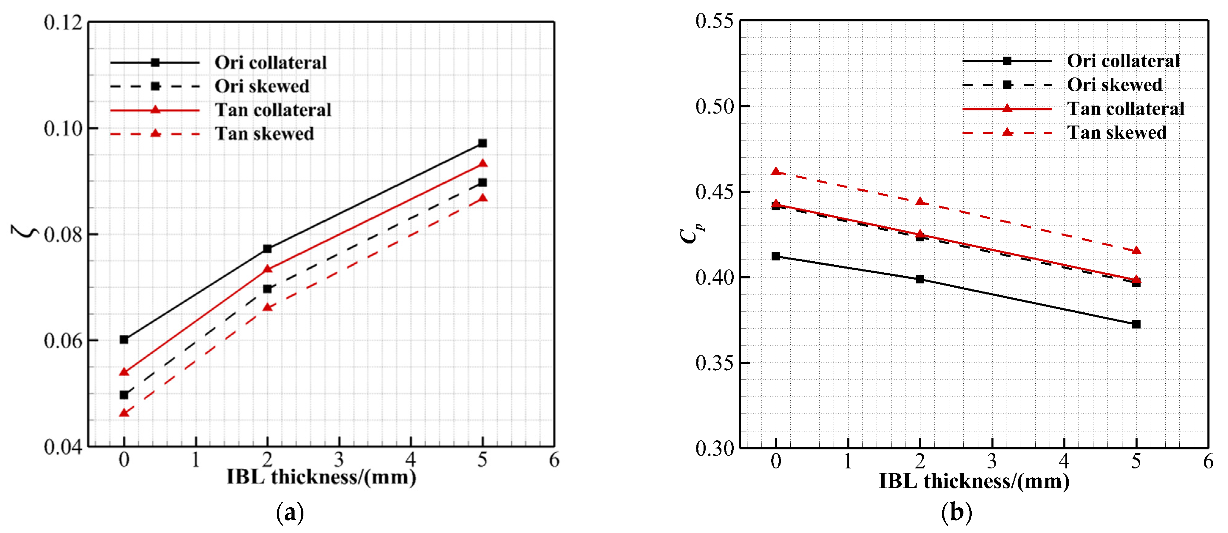
In general, studies on the impact of the IBL have mostly focused on the conventional single cascade, and less work has combined the IBL thickness and the IBL skew. In addition, the tandem stator is located in the middle or rear stage of multistage compressors in the current practical application, so the IBL influence on the aerodynamic performance of the tandem blades cannot be ignored, but there are few related studies at present. Therefore, in this paper, the tandem design of the conventional single blade was firstly carried out. Then, the effects of the conventional collateral IBL and the skewed IBL on the flow field structure and aerodynamic performance of the single blade under different IBL thicknesses were compared and analyzed. Finally, for the designed tandem cascade, the effects of the incidence angle and the IBL (thickness and skew) on its flow field characteristics and aerodynamic performance were analyzed in detail.

2. Researched Compressor Cascade and Numerical Method

In this paper, a high subsonic compressor stator cascade based on the NACA65 K48 blade profile was selected as the original cascade. The design parameters are shown in Table 1. In the design state, the inlet Mach number ( M a 1 ) is 0.67 and the Reynolds number based on blade chord length and inlet velocity is 5.6 × 10 5 . In addition, the low aspect ratio design of the original cascade is a classical middle-stage compressor blade design, so as to focus on the development of the endwall secondary flow in the corner separation.
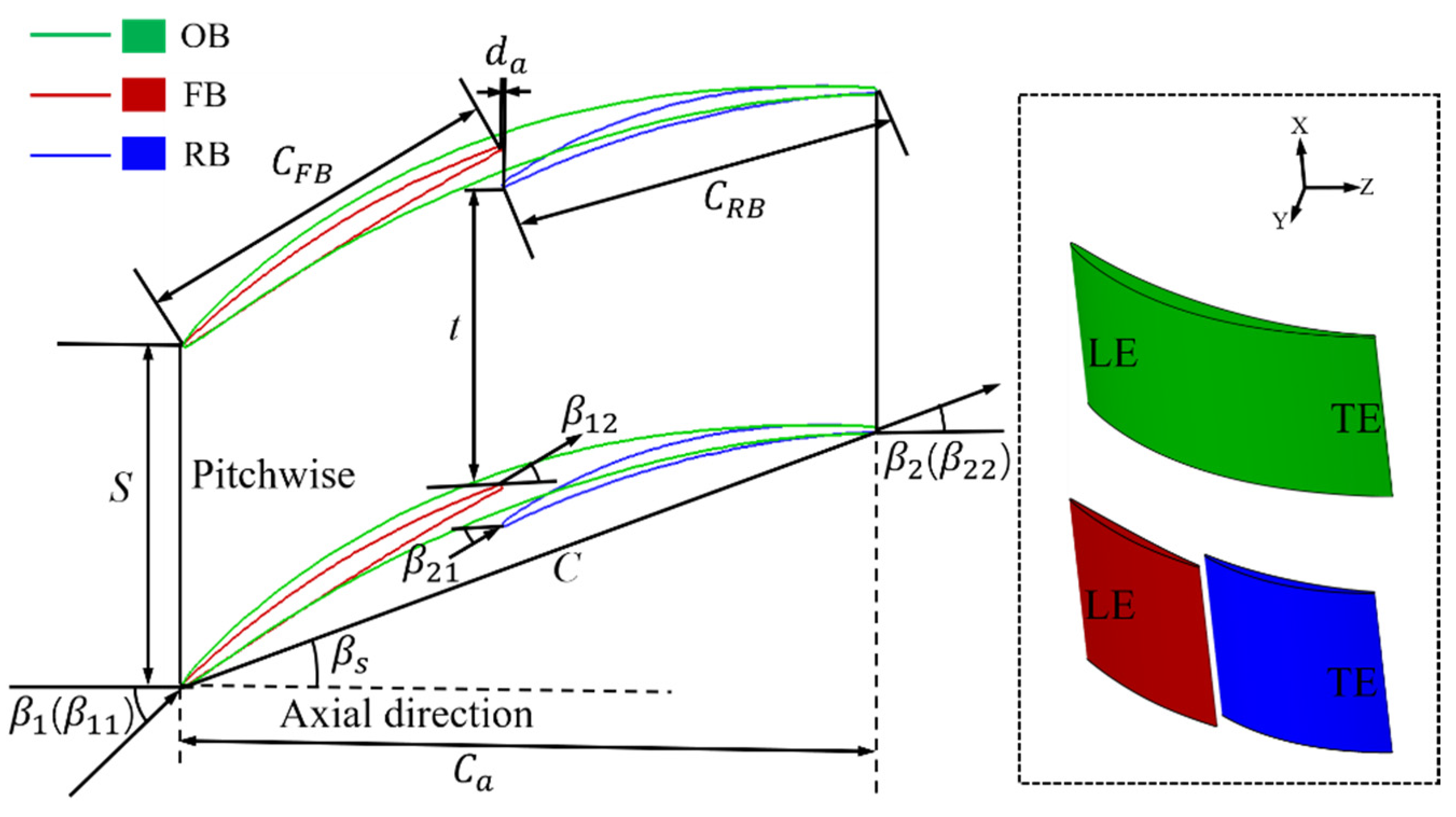
Under the condition of ensuring that the modeling parameters of the original cascade remained unchanged, the tandem modification design of the original blade profile was carried out in this paper. A more detailed tandem cascade blade design process can be found in Chen’s work [28]. The 2D blade profile and the 3D straight blade of the original cascade and tandem cascade are given in Figure 1. It should be pointed out that in order to obtain tandem cascades with better performance, after referring to the relatively consistent conclusions in the previous literature [9,10,11,12], this paper selected the values of five geometric parameters of the tandem cascade, as shown in Table 2. AO represents the axial overlap, PP represents the percent pitch, CR represents the chord ratio, TR represents the camber ratio, and KBB represents the approximate incidence angle of the RB.
This paper adopted the commercial computational fluid dynamics software ANSYS CFX to perform the 3D steady Reynolds-averaged Navier–Stokes (RANS) simulations for the original and tandem cascades. The space term discretization adopted the high-resolution difference format, which can guarantee the second-order accuracy, and the time term was discretized using the second-order backward Euler method. Considering fully developed turbulence and near-wall turbulence simulations, the SST k-ω turbulence model was used [29,30]. It has been proven by previous literature studies that it can predict the flow field characteristics of the compressor well [31,
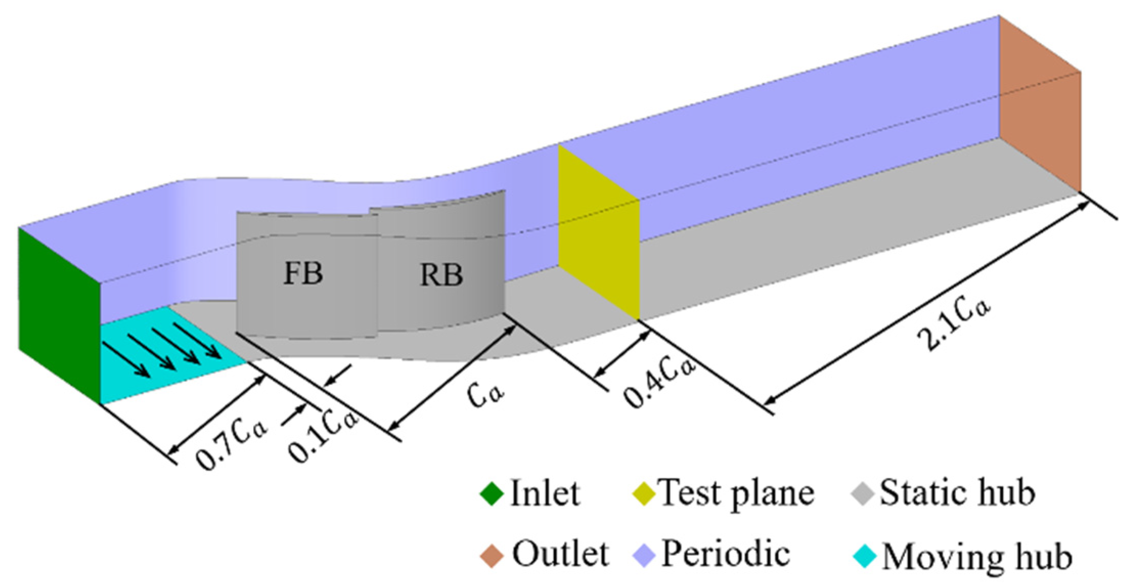
32]. Taking the tandem cascade as an example, Figure 2 shows the schematic diagram of the computational domain. The computational domain is a single blade passage, and a periodic boundary was applied as translational extension in the circumferential direction of the linear cascade. Both the blade and endwall were set as adiabatic nonslip walls. At the same time, owing to the cascade flow symmetry in the spanwise direction, a symmetrical boundary condition was adopted at the midblade position. So, only half of the blade span was simulated to reduce the computational cost. In addition, the computational domain inlet was selected at 0.8 times axial chord length ( C a ) away from the FB leading edge, and the total temperature, total pressure distribution, flow direction, turbulence intensity (4%), and turbulence length scale (0.004 m) were given at the inlet. The outlet was situated at 2.5 C a away from the RB trailing edge to reduce the reflections influence from the outlet boundary on the results obtained from the test plane (0.4 C a ) away from the RB trailing edge. We adjusted the static pressure at the outlet to ensure an inlet Mach number ( M a 1 ) of 0.67. It is worth mentioning that the aerodynamic parameters on the test plane were selected by this study to conduct the cascade performance analysis, so it is the real outlet in this paper.
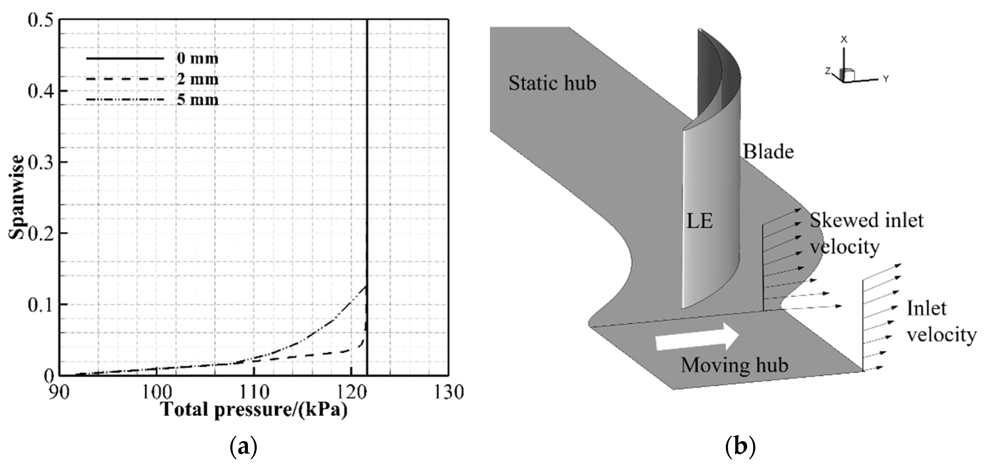
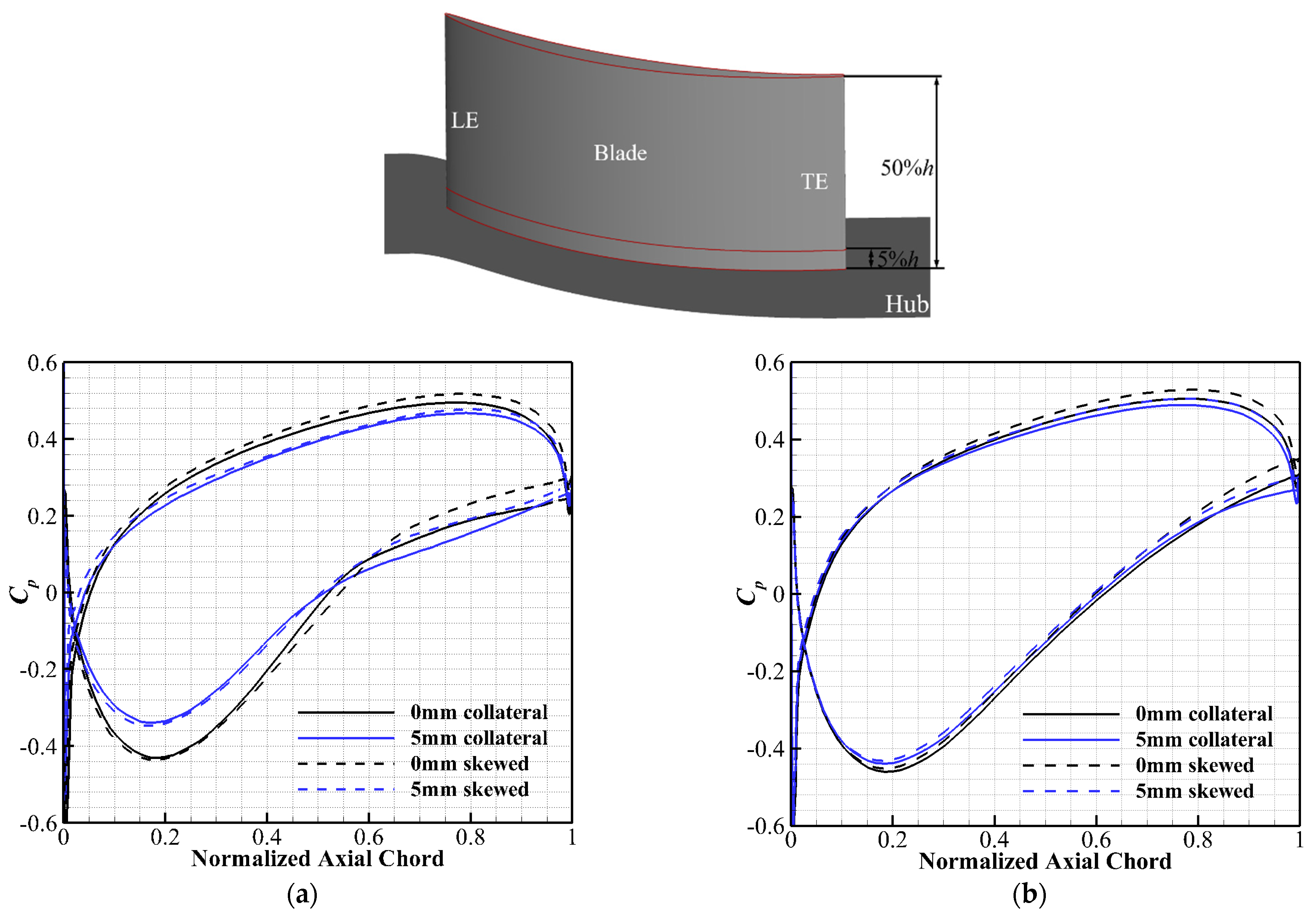
Three different IBL thicknesses (0 mm, 2 mm, and 5 mm) were selected according to the cascade parameters, and their relative blade height ratios are 0%, 5%, and 12.5%, respectively. The corresponding calculational domain inlet boundary conditions were given according to the total pressure spanwise distributions, which are shown in Figure 3a. In addition, this paper used a moving endwall to introduce a boundary layer skew, and the numerical simulation principle of the boundary layer skew is shown in Figure 3b. As shown in Figure 2, the moving hub was set in the range of 0.1–0.8 C a upstream of the FB leading edge, and its speed is 200 m/s.
In the present investigation, the structured multiblock O4H-type topological grids of the original cascade were automatically generated by the AutoGrid5 in NUMECA software. The tandem cascade grids were formed by periodically matching and connecting the O4H-type topological grids of the FB and RB, thereby ensuring that the grid orthogonality is greater than 10°. Additionally, we locally densify the blade surface and endwall meshes to meet the requirement that the y + value near the wall is less than 1 in the SST k-ω turbulence model. 
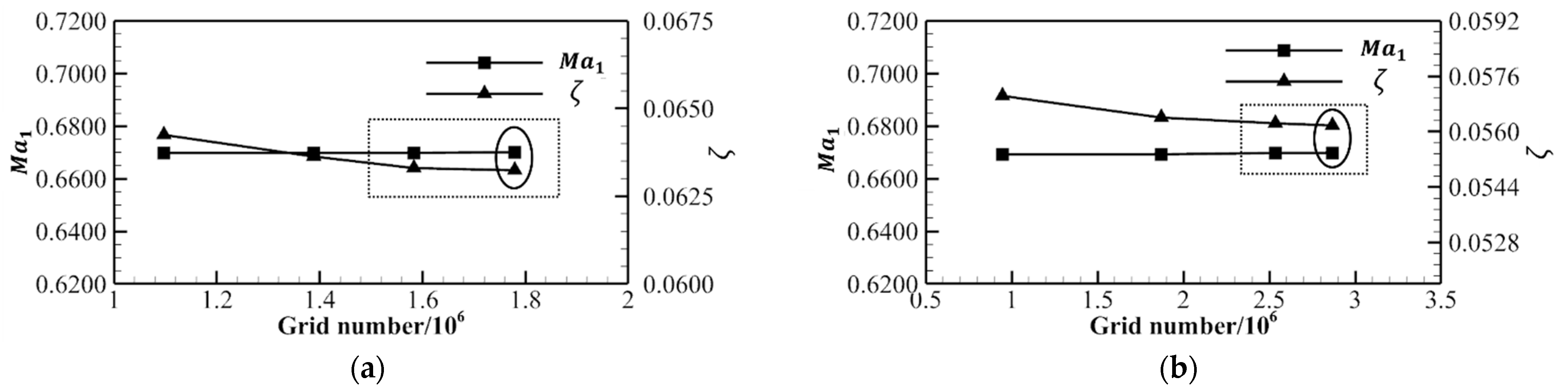
Figure 4 shows the variation of M a 1 and the overall total pressure loss coefficient ( ζ ) of the original and tandem cascades with different grid numbers for grid independence verification. The total pressure loss coefficient is defined as:
ζ = P t 1 P t P t 1 p 1
where the inlet total pressure, inlet static pressure, and local total pressure are represented by P t 1 , p 1 , and P t , respectively. Under the premise of considering the computational cost and accuracy, the total grid numbers of the original and tandem cascades were finally selected as 1.78 million and 2.86 million, respectively. 
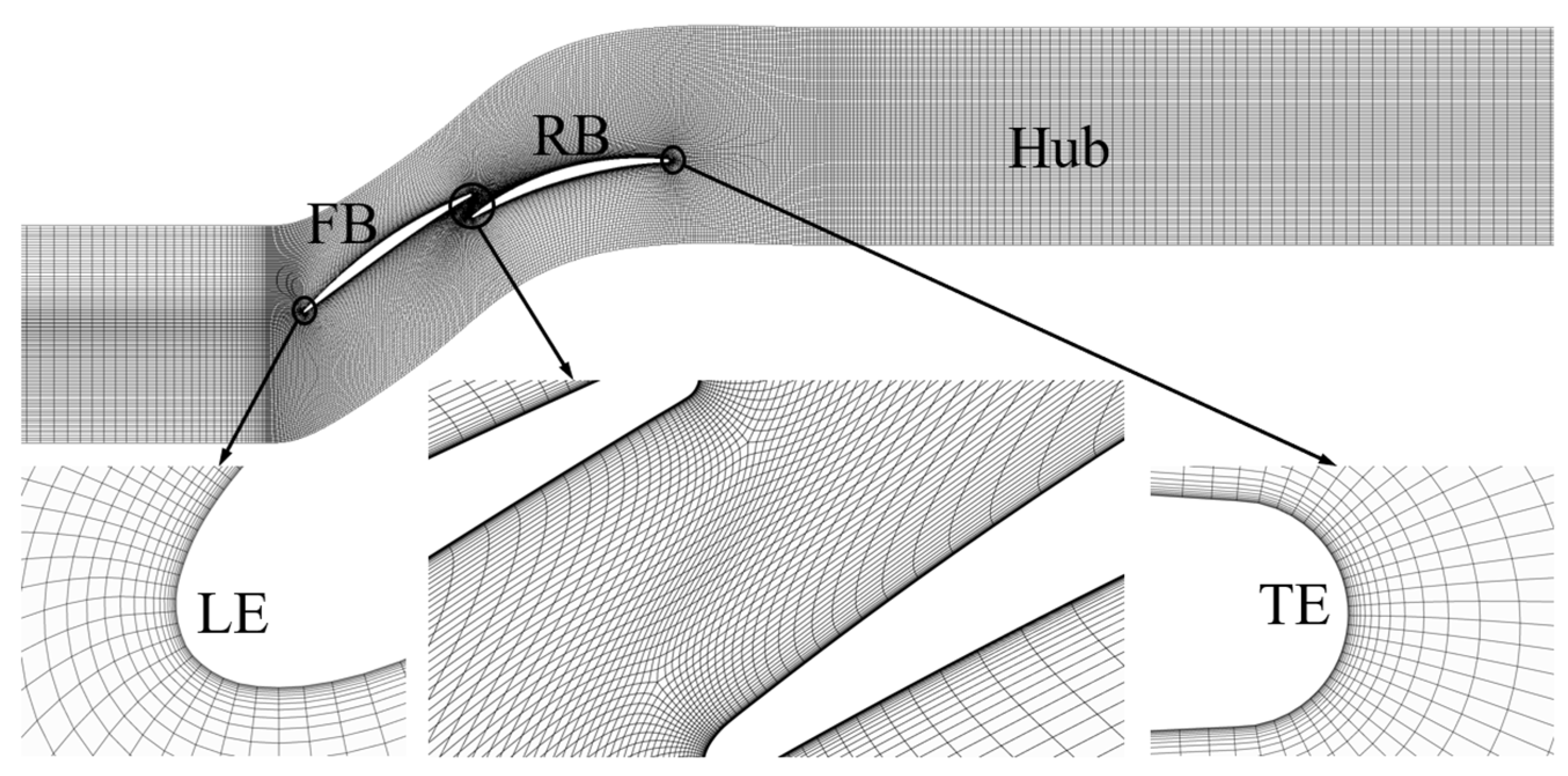
Figure 5 shows the endwall meshes of the tandem cascade, and an enlarged view of the partial mesh at the leading edge (LE), the trailing edge (TE), and the gap between the FB and RB are also shown.
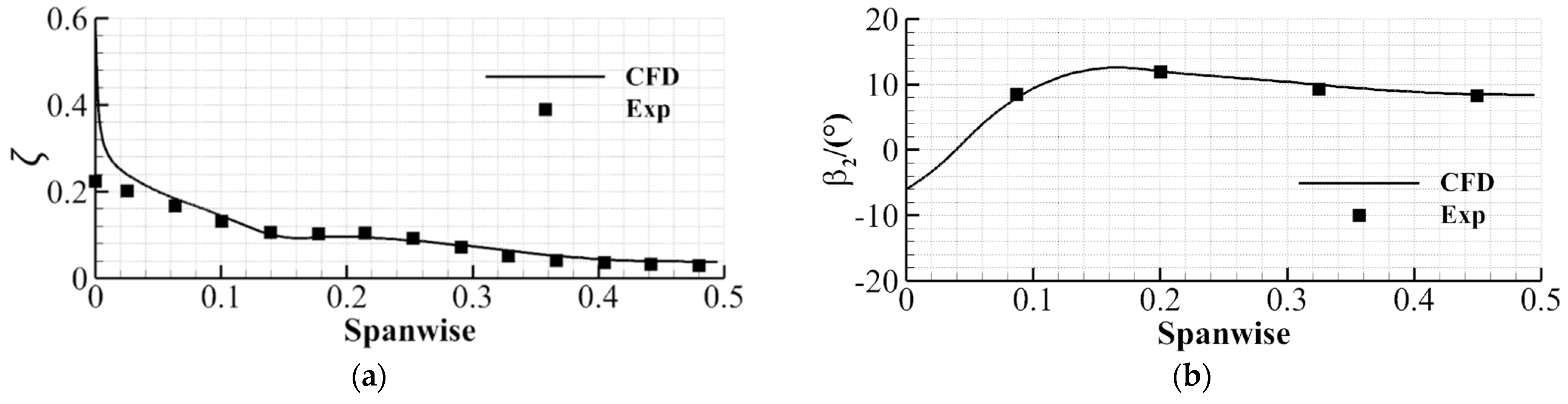
In order to further verify the accuracy of the numerical method, in terms of the outlet total pressure loss coefficient and outlet flow angle distributions along the spanwise direction, the numerical and experimental results [33] of the original cascade are compared at the design condition, which is shown in Figure 6. It can be found that the outlet airflow angle of numerical simulation is in good agreement with the experimental results, but there are some errors concerning the total pressure loss coefficient near the endwall region. However, this was relatively common in previous literature studies [33,
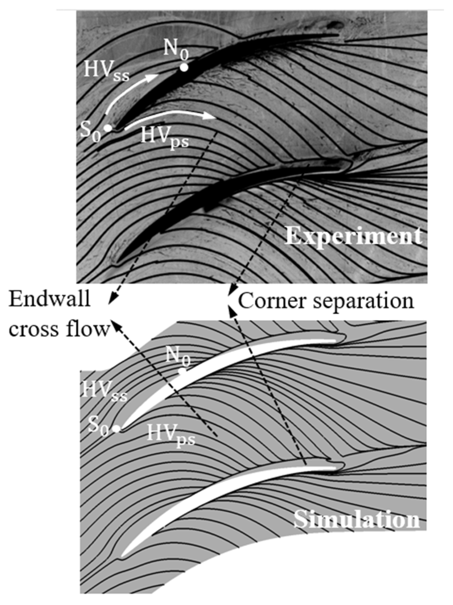
34]. In addition, based on the endwall limiting streamlines of the original cascade, Figure 7 compares the oil-flow experimental results [35] with the simulated results. Obviously, the simulated flow patterns on the endwall show a good agreement with the experimental flow patterns, including the saddle point S 0 , node N 0 , suction side leg of horseshoe vortex ( HV ss ), pressure side leg of horseshoe vortex ( HV ps ), cross flow, and corner separation regions, which gives us confidence to draw conclusions about the change of flow fields and cascade performance.

3. Results and Discussion

3.1. Original Cascade Aerodynamic Performance

Firstly, in order to highlight the advantages of the tandem cascade design, this paper uses the total pressure loss coefficient ( ζ ) and static pressure rise coefficient ( C p ) for evaluation. The static pressure rise coefficient is defined as:
C p = p p 1 P t 1 p 1
where the inlet total pressure, inlet static pressure, and local static pressure are represented by P t 1 , p 1 , and p , respectively. Figure 8 shows the variation of the overall outlet total pressure loss coefficient and the static pressure rise coefficient with the IBL thickness for the original cascade and tandem cascade under different IBL conditions (collateral and skewed) at the design incidence angle. Under the same condition, the parameter differences between the tandem cascade and the original cascade are shown in Table 3 and Table 4. “Ori” means original cascade and “Tan” means tandem cascade. It can be seen that, compared with the original cascade, the tandem cascade can effectively reduce the loss and improve the diffusing capacity under different working conditions. In addition, compared with the skewed IBL cases, the advantage of tandem cascade in the collateral IBL cases is more obvious. Regarding the IBL influence on the tandem cascade, this paper will conduct a detailed analysis in Section 3.2.
For the original cascade, the skewed IBL can effectively reduce the loss and increase the diffusing capacity compared with the collateral IBL. However, it can be found from Figure 8 that an increase in the IBL thickness suppresses the advantage of the skewed IBL. The detailed analyses are as follows.
Figure 9 shows the limiting streamlines and static pressure contours of the original cascade endwall and suction surface. Here, “0 mm collateral” means that the IBL thickness is 0 mm, and it is collateral IBL. As shown in Figure 9a, the saddle point S(N1) located on the suction surface and endwall is the starting point of the 3D corner separation. The region composed of saddle point S(N1), suction surface separation line (SL), and endwall reverse flow line is the 3D corner separation region. As shown in Figure 9b, when the IBL thickness increases, the low-energy fluid in the endwall increases, which leads to stronger cross flow and reverse flow. Therefore, the saddle point S(N1) moves to the blade leading edge (LE), and the range of the reverse flow line and SL becomes wider. This indicates a more serious corner separation. In addition, the concentrated shedding vortex (CSV) located on the suction surface of Figure 9a disappears.
Since the flow direction of the fluid in the skewed IBL upstream of the blade passage is opposite to the cross flow direction on the endwall, it inhibits the development of the endwall cross flow, i.e., it leads to a weaker cross flow. As shown in Figure 9c,d, the saddle point S(N1) moves towards the blade trailing edge (TE) and the range of the reverse flow line and SL narrows. In general, compared with the collateral IBL, the skewed IBL can alleviate the cascade corner separation, thus reducing the loss and increasing the diffusing capacity, which can be seen in the static pressure contours.
In order to quantitatively analyze the IBL effect, Figure 10 shows the C p distributions of the blade surface along the normalized axial chord ( C a ) of the original cascade at 5% h and 50% h. At 5% h, the influence of the IBL thickness as well as the skewed IBL is obvious. It can be seen that the thickened IBL reduces the blade load (pressure difference between suction and pressure surfaces) and axial inverse pressure gradient within 0–50% C a . It is mainly due to the more blade passage flow blockage caused by the low energy fluid in the boundary layer. In addition, the skewed IBL increases the blade load within 0–50% C a . and the axial reverse pressure gradient within 0–100% C a at 0 mm cases, thus increasing the blade diffusion capacity. However, in the 5 mm cases, although the skewed IBL still has a positive effect on the blade diffuser capacity, the effect is small. The C p distributions at 50% h are generally similar to that at 5% h, and the IBL effect is not obvious.
The distributions of the mass pitch-averaged outlet total pressure loss coefficient and the outlet flow angle of the original cascade along the spanwise are shown in Figure 11. As shown in Figure 11a, it is evident that the thickened IBL directly increases the loss within the full span. In addition, the skewed IBL has lower losses within approximately 5–50% h, but higher losses within 0–5% h. Through outlet flow angle profiles, we can get the law of the IBL influence on the outlet flow angle. The thickened IBL will aggravate the outlet flow angle overturning and underturning, while the influence of skewed IBL is the opposite.
According to Watzlawick’s description [36], it can be known that the NACA65 K48 cascade outlet flow angle distribution is mainly affected by the passage vortex (PV). It is well known that PV is formed by the circumferential flow (cross flow) of the endwall low-energy fluid in the blade passage. Figure 12 shows the axial velocity ( V z ) contours and streamlines of the cut planes (90% C a ) perpendicular to the axial direction for further analyses. When the IBL thickness increases, the low-energy fluid near the endwall increases, which leads to a stronger cross flow and PV vorticity and structure scale, while the low-energy fluid further develops along the spanwise (as shown in V z contours), thus causing the loss and outlet flow angle distributions seen in Figure 11. Furthermore, as shown in Figure 12c, the skewed IBL has a suppressive effect on the cross flow and PV development, so the PV structure scale is smaller and the vortex core is at a lower spanwise position. This explains the skewed IBL effect on the loss and outlet flow angle distributions in Figure 11. Finally, as shown in Figure 12d, in the thick IBL cases, the inhibitory effect of the skewed IBL on PV is weakened, but it also has a certain influence on the PV vortex core circumferential position.

3.2. Tandem Cascade Aerodynamic Performance

In this section, a detailed analysis of the IBL effect on tandem cascade is carried out. First of all, the flow field characteristics and aerodynamic performance at the design incidence angle (0°) and 4° incidence angle are analyzed in turn. Finally, the overall aerodynamic performance of the tandem cascade is evaluated by the overall outlet total pressure loss coefficient and the static pressure rise coefficient in the range of full incidence angles.

3.2.1. Flow Patterns and Aerodynamic Performance at 0° Incidence Angle

Figure 13 shows the streamlines and Mach number (Ma) contours of the tandem cascade at 5% h and 50% h under different IBL conditions. As we all know, the tandem blade (2D) control principle can be divided into two parts. On the one hand, the flow deceleration and diffusion of the tandem blades are realized on the FB and RB, respectively, and this structure inhibits the development of the boundary layer on the blade surface. Comparing Figure 9 and Figure 13, we can also observe this feature. On the other hand, it can be seen from Figure 13a that there is a high-momentum fluid in the passage formed between the FB trailing edge pressure surface and the RB leading edge suction surface, which is called “gap flow” in this paper. The gap flow can effectively weaken the mixing of the FB and RB wakes near the RB trailing edge. Comparing Figure 13a and Figure 13b, it can be found that the thickened IBL will weaken the momentum of the gap flow. At the same time, the thickened IBL increases the low-energy fluid in the FB wake, so in Figure 13b, the low-energy fluid in the FB wake and the RB wake are seriously mixed. This results in a larger circumferential range of low energy near the RB trailing edge, and the same phenomenon can also be observed in Figure 13d.
Comparing the “0 mm collateral” case and the “0 mm skewed” case at 5% h, the gap flow strength is about the same, but the low energy fluid in the RB wake is significantly less at the “0 mm skewed” case. The reason is that the skewed IBL effect inhibits the flow near the endwall (cross flow) towards the RB suction surface, as in the analyses of Figure 9c above. Then, as shown in Figure 13e–h, the IBL has little effect on the tandem cascade main flow area (50% h).
Figure 14 shows the C p distributions of the blade surface along the normalized axial chord of the tandem cascade at 5% h and 50% h. Comparing Figure 14 and Figure 10, at 5% h we find that the original cascade diffusing capacity decreases significantly after 50% C a , but the tandem cascade decreases after 80% C a . At 50% h, the original cascade diffusing capacity near the trailing edge region is slightly decreased, especially for the “5 mm collateral” case, but this does not occur in the tandem cascade. From Figure 14a, it can be directly seen that the IBL thickness reduces the FB load and the axial reverse pressure gradient, but the effect of the skewed IBL seems to be small. In the “0 mm collateral” case, the RB diffusing capacity near the trailing edge region (80–100% C a ) disappears, implying that severe boundary layer separation occurs here. In the “5 mm collateral” case, the RB has weaker boundary layer separation. The reason is that the presence of the IBL increases the low-energy fluid near the endwall and causes the blockage of the flow passage, which reduces the RB load and the axial reverse pressure gradient. Combining Figure 13a and Figure 14c, we can find that the skewed IBL effect on the weakening RB boundary layer separation is positive. In addition, from the C p distributions in Figure 14b, we can again find that the IBL has little effect on the tandem cascade aerodynamic performance.
In order to clearly understand the tandem cascade 3D corner separation under the IBL influence, Figure 15 shows the 3D streamlines of the blade passage under different IBL conditions. Two cut planes (S1 and S2) perpendicular to axial direction V z contours are also shown in Figure 15. It should be noted that S1 is located in the FB corner separation region, and S2 is located in the RB corner separation region. In addition, for the 3D streamlines, red represents the streamlines about the FB corner separation, black represents the streamlines about the RB corner separation, blue represents the gap flow streamlines near the endwall, and green represents the PV streamlines. As shown in Figure 15a, the gap flow effectively inhibits the mixing of the low-energy fluid in the FB wake and the RB corner region. The low-energy fluid of the RB corner separation comes from the middle of the upstream blade passage, and the FB passage is free of PV.
As shown in Figure 15b, when the IBL thickness increases, it can be seen that the PV of the FB appears, and the FB wake increases significantly. In addition, there is a stronger cross flow here to create the RB corner separation, and the suppression of the gap flow becomes less. As shown in Figure 16, the gap flow in the endwall region has lower normalized axial momentum (NAM) under the thicker IBL. It can also be found in Figure 16 that the skewed IBL will reduce the gap flow momentum, but the effect is very small. Comparing Figure 15a and Figure 15c, it can be found that the skewed IBL effectively inhibits the development of the blade passage cross flow, so there is a smaller PV structure scale and FB wake, and a weaker RB corner separation.
Figure 17 shows the distributions of the mass pitch-averaged outlet total pressure loss coefficient and the outlet flow angle of the tandem cascade along the spanwise. Comparing Figure 11a and Figure 17a, in the mainstream area (40–50% h), the tandem cascade 2D performance advantage is well reflected. The IBL thickness is positively correlated with the tandem cascade loss, which is the same as the original cascade. Comparing Figure 11b and Figure 17b, under the same IBL conditions, the tandem cascade outlet flow angle has a weaker underturning, stronger overturning, and smaller overturning range. This indicates that the tandem cascade PV vorticity is stronger, but the PV structure scale is smaller. In addition, compared with the collateral IBL, the skewed IBL increases the tandem cascade loss, and the suppression of the outlet flow angle overturning and underturning are obvious. However, as the IBL thickness increases, this inhibitory effect weakens. Especially in the case of 5 mm, it can be found from Figure 17b that the distributions of the outlet flow angle are almost the same under the conditions of the collateral IBL and the skewed IBL.

3.2.2. Flow Patterns and Aerodynamic Performance at 4° Incidence Angle

Figure 18 shows the streamlines and Mach number contours of the tandem cascade at 5% h under different IBL conditions. Compared with Figure 13, it can be found that, when the incidence angle increases, the strength of the gap flow decreases, which explains the serious mixing of the FB and RB wakes in Figure 18a. Furthermore, when the IBL thickness increases, the RB wake decreases significantly. Combined with the C p distributions of the blade surface along the normalized axial chord of the tandem cascade at 5% h, as shown in Figure 19, we find that the reason is that, under the influence of incidence angle and IBL thickness, the FB boundary layer serious separation and caused serious blade passage blockage. Consequently, the RB diffuser capacity is reduced and there is less boundary layer separation. In addition, combined with Figure 18c,d, and Figure 19, it can be known that the skewed IBL has a positive effect on inhibiting the FB boundary layer separation (the “5 mm” case) and the RB boundary layer separation (the “0 mm” case).
Figure 20 shows the 3D streamlines of the blade passage and V z contours under different IBL conditions. The positions of the two cut planes (S1 and S2) perpendicular to the axial direction and the color coding of the 3D streamlines are the same as in Figure 15. When the incidence angle is 4°, the overall characteristics of the flow field are the same as when the incidence angle is 0°, but the cross flow strength and the PV vorticity increase. Moreover, with the increase of the incidence angle, the FB wake loss increases, but the RB wake loss decreases, which is consistent with the analysis of Figure 18. In addition, Figure 21 shows the distributions of mass pitch-averaged outlet total pressure loss coefficient of the tandem cascade along the spanwise. Compared with Figure 17a, it can be seen that after the incidence angle increases, the IBL effect on the loss distribution remains unchanged. Moreover, after the incidence angle increases, the high loss range expands to the mainstream area (40–50% h).

3.2.3. Overall Performance

Figure 22 shows the variation of the total pressure loss coefficient and the static pressure rise coefficient with the incidence angle under different IBL conditions. The first discussion is the influence of the IBL thickness. From Figure 22, we can intuitively see the positive correlation between the IBL thickness and the loss, and the negative correlation between the IBL thickness and the static pressure rise (except for the −6° incidence angle). Furthermore, the IBL thickness has no effect on the incidence angle characteristic distribution as a whole, except for changing the minimum loss point (from 0° to −2°).
Then, we will analyze the influence of the skewed IBL. Under the same IBL thickness, the parameter differences compared with the collateral IBL are shown in Table 5 and Table 6. In the range of the −4°~7° incidence angle, the skewed IBL can effectively reduce the loss and increase the static pressure rise. However, at the −6° incidence angle, especially for the static pressure rise, the skewed IBL has a negative effect. Interestingly, at the 0 mm case, the minimum loss incidence angle is 2°. In addition, at the 0° incidence angle or the 2° incidence angle, the performance improvement effect of the skewed IBL on the tandem cascade is the best. The positive effect of the skewed boundary layer diminishes as it tends towards a larger positive incidence angle or a smaller negative incidence angle. Finally, at the same incidence angle, when the IBL thickness increases, the positive effect of the skewed IBL is continuously weakened.

4. Conclusions

This paper took the high subsonic compressor NACA65 K48 cascade as the original cascade, which was designed in a reasonable tandem structure. Using the numerical simulation method, the IBL (thickness and skewed) influence on the 3D flow field structure and aerodynamic performance of the original cascade and tandem cascade were investigated. The main conclusions obtained are as follows:
(1)
Under different IBL conditions, the tandem cascade effective design makes it better than original cascade in the aerodynamic performance. In addition, compared with the collateral IBL, the skewed IBL can effectively improve the aerodynamic performance of the original cascade and tandem cascade. However, an increase in the IBL thickness will suppress this advantage.
(2)
The tandem cascade gap flow strength decreases with the increase of the incidence angle. When the IBL thickness increases, the gap flow strength near the endwall decreases, so the mixing of the FB wake and the RB wake in the near-endwall region is more serious. Moreover, the skewed IBL has little effect on the gap flow strength.
(3)
The increase of incidence angle or IBL thickness will make tandem cascade FB corner separation more serious and cause the flow passage to be blocked, which seriously affects (reduces) the RB diffusing capacity. Furthermore, the skewed IBL effectively alleviates the FB and RB corner separation by suppressing the development of the endwall cross flow.
(4)
The IBL thickness is positively correlated with the tandem cascade total pressure loss and negatively correlated with the static pressure rise (except for the −6° incidence angle). The skewed IBL can effectively reduce the total pressure loss and increase the static pressure rise within the −4°~7° incidence angle, but the law is opposite at the −6° incidence angle. At the 0° or 2° incidence angle, the performance improvement effect of the skewed IBL on the tandem cascade is the best, and this positive effect diminishes as it tends towards a larger positive incidence angle or a smaller negative incidence angle.

Author Contributions

Z.Y. conducted the simulations and did the analysis. B.L., B.Z. and H.W. put forward the main idea and supervised the research work. Z.Y. and X.M. drafted the manuscript, discussed the results, and reviewed the manuscript. All authors have read and agreed to the published version of the manuscript.

Funding

This research is funded by the National Natural Science Foundation of China (project no: 51790512) (project no: 52106057), the National Major Science and Technology Projects of China (project no: 2017-II-0001-0013), the Fundamental Research Funds for the Central Universities (project no: D5000210483), and the Funds of National Key Laboratory of Science and Technology on Aerodynamic Design and Research (project no: D5150210006).

Conflicts of Interest

The authors declare no conflict of interest.

Nomenclature

Symbols
C a Axial chord length
C p Static pressure rise coefficient
iIncidence angle
MaMach number
NAMNormalized axial momentum
p 1 Inlet static pressure
p Local static pressure
P t 1 Inlet total pressure
P t Local total pressure
y + Nondimensional wall distance
V z Axial velocity
ζ Total pressure loss coefficient
β 2 Outlet flow angle
Abbreviations
2/3DTwo/Three-dimensional
AOAxial overlap
CRChord ratio
CSVConcentrated shedding vortex
FBForward blade
IBLInlet boundary layer
KBBRear blade approximate incidence angle
LELeading edge
PPPercent pitch
PSPressure surface
PVPassage vortex
RBRear blade
SLSeparation line
SSSuction surface
TETrailing edge
TRCamber ratio

References

  1. Wennerstrom, A.J. Highly Loaded Axial Flow Compressors: History and Current Developments. J. Turbomach. 1990, 112, 567–578. [Google Scholar] [CrossRef]
  2. Gbadebo, S.A.; Cumpsty, N.A.; Hynes, T.P. Three-Dimensional Separations in Axial Compressors. J. Turbomach. 2005, 127, 331–339. [Google Scholar] [CrossRef]
  3. Wei, M.A.; Ottavy, X.; Lipeng, L.U.; Leboeuf, F.; Feng, G.A. Experimental study of corner stall in a linear compressor cascade. Chin. J. Aeronaut. 2011, 24, 235–242. [Google Scholar]
  4. Ju, Y.; Zhang, C. Multi-objective optimization design method for tandem compressor cascade at design and off design conditions. In Proceedings of the ASME Turbo Expo 2010: Power for Land, Sea, and Air, Glasgow, UK, 14–18 June 2010. [Google Scholar]
  5. Cao, Z.; Gao, X.; Zhang, X.; Zhang, F.; Liu, B. Effect of endwall passage vortex generator on corner stall of a tandem compressor cascade. Int. J. Heat Fluid Flow 2022, 94, 108946. [Google Scholar] [CrossRef]
  6. Omidi, M.; Liu, Y.; Mohtaram, S.; Li, S. Investigating on performance parameters and flow field of centrifugal compressor based on the splitter blade leading edge’s location effect. J. Mech. Sci. Technol. 2022, 36, 4015–4020. [Google Scholar] [CrossRef]
  7. Hoeger, M.; Baier, R.D.; Fischer, S.; Neudorfer, J. High turning compressor tandem cascade for high subsonic flows, part 1: Aerodynamic design. In Proceedings of the 47th AIAA/ASME/SAE/ASEE Joint Propulsion Conference & Exhibit, San Diego, CA, USA, 31 July–3 August 2011. [Google Scholar]
  8. Tesch, A.; Lange, M.; Vogeler, K.; Ortmanns, J.; Johann, E.; Gümmer, V. An experimental investigation of a tandem stator flow characteristic in a low speed axial research compressor. In Proceedings of the ASME Turbo Expo 2014: Turbine Technical Conference and Exposition, Düsseldorf, Germany, 16–20 June 2014. [Google Scholar]
  9. Ohashi, H. Theoretical and experimental investigations on tandem pump cascades with high deflection. Ing. Arch. 1959, 27, 201–226. [Google Scholar] [CrossRef]
  10. Schluer, C.; Bohle, M.; Cagna, M. Numerical investigation of the secondary flows and losses in a high turning tandem com-pressor cascade. In Proceedings of the 8th European turbomachinery conference, Graz, Austria, 23–27 March 2009. [Google Scholar]
  11. McGlumphy, J.; Ng, W.F.; Wellborn, S.R.; Kempf, S. Numerical investigation of tandem airfoils for subsonic axial-flow com-pressor blades. J. Turbomach. 2009, 131, 021018. [Google Scholar] [CrossRef]
  12. McGlumphy, J.; Ng, W.-F.; Wellborn, S.R.; Kempf, S. 3D Numerical Investigation of Tandem Airfoils for a Core Compressor Rotor. J. Turbomach. 2010, 132, 031009. [Google Scholar] [CrossRef]
  13. Heinrich, A.; Tiedemann, C.; Peitsch, D. Experimental investigations of the aerodynamics of highly loaded tandem vanes in a high-speed stator cascade. In Proceedings of the ASME Turbo Expo 2017: Turbomachinery Technical Conference and Exposition, Charlotte, CA, USA, 26–30 June 2017. [Google Scholar]
  14. Hertel, C.; Bode, C.; Kožulović, D.; Schneider, T. Investigations on aerodynamic loading limits of subsonic compressor tandem cascades: End wall flow. In Proceedings of the ASME Turbo Expo 2014: Turbine Technical Conference and Exposition, Düsseldorf, Germany, 16–20 June 2014. [Google Scholar]
  15. Zhang, L.; Wang, S.; Zhu, W. Application of endwall contouring in a high-subsonic tandem cascade with endwall boundary layer suction. Aerosp. Sci. Technol. 2018, 84, 245–256. [Google Scholar] [CrossRef]
  16. Cao, Z.; Guo, W.; Song, C.; Liu, B. Flow physics of highly loaded tandem compressor cascade with non-axisymmetric endwall profiling. Proc. Inst. Mech. Eng. Part A J. Power Energy 2020, 235, 931–943. [Google Scholar] [CrossRef]
  17. Denton, J.D. Some limitations of turbomachinery CFD. In Proceedings of the ASME Turbo Expo 2010: Power for Land, Sea, and Air, Glasgow, UK, 14–18 June 2010. [Google Scholar]
  18. Gbadebo, S.A. Three-Dimensional Separations in Compressors. Ph.D. Thesis, University of Cambridge, Cambridge, UK, 2004. [Google Scholar]
  19. Guo, S.; Lu, H.; Chen, F.; Wu, C. Vortex control and aerodynamic performance improvement of a highly loaded compressor cascade via inlet boundary layer suction. Exp. Fluids 2013, 54, 1570. [Google Scholar] [CrossRef]
  20. Gao, F. Advanced Numerical Simulation of Corner Separation in a Linear Compressor Cascade. Ph.D. Thesis, Ecole Centrale de Lyon, Écully, France, 2014. [Google Scholar]
  21. Zhang, L.; Wang, S. A combination application of tandem blade and endwall boundary layer suction in a highly loaded aspirated compressor outlet vane. Proc. Inst. Mech. Eng. Part A J. Power Energy 2018, 232, 129–143. [Google Scholar] [CrossRef]
  22. Moore, R.W., Jr.; Richardson, D.L. Skewed boundary-layer flow near the end walls of a compressor cascade. J. Fluids Eng. 1957, 79, 1789–1797. [Google Scholar] [CrossRef]
  23. Demargne, A.A.J.; Longley, J.P. The aerodynamic interaction of stator shroud leakage and mainstream flows in compressors. In Proceedings of the ASME Turbo Expo 2000: Power for Land, Sea, and Air, Munich, Germany, 8–11 May 2000. [Google Scholar]
  24. Böhle, M.; Stark, U. A numerical investigation of the effect of end-wall boundary layer skew on the aerodynamic performance of a low aspect ratio, high turning compressor cascade. In Proceedings of the ASME 2007 International Mechanical Engineering Congress and Exposition, Washington, NA, USA, 11–15 November 2007. [Google Scholar]
  25. Lei, V.-M.; Spakovszky, Z.S.; Greitzer, E.M. A Criterion for Axial Compressor Hub-Corner Stall. J. Turbomach. 2008, 130, 031006. [Google Scholar] [CrossRef]
  26. Li, X.; Chu, W.; Wu, Y. Numerical investigation of inlet boundary layer skew in axial-flow compressor cascade and the cor-responding non-axisymmetric end wall profiling. Proc. Inst. Mech. Eng. Part A J. Power Energy 2014, 228, 638–656. [Google Scholar] [CrossRef]
  27. Bode, C.; Hoffmann, J.; Stark, U. Effects of a Skewed Inlet Boundary Layer on the Aerodynamic Performance of a Stator-Hub Equivalent High-Turning Compressor Cascade. In Proceedings of the ASME Turbo Expo 2016: Turbomachinery Technical Conference and Exposition, Seoul, Korea, 13–17 June 2016. [Google Scholar]
  28. Chen, H.; Liu, B.; Li, J.; Yang, X. A study of parameter optimization of axial compressor tandem cascade. J. Propuls. Technol. 2017, 38, 2224–2234. (In Chinese) [Google Scholar]
  29. Menter, F.R.; Langtry, R.B.; Likki, S.R.; Suzen, Y.B.; Huang, P.G.; Volker, S. A correlation-based transition model using local variables: Part I—model formulation. In Proceedings of the ASME Turbo Expo 2004: Power for Land, Sea, and Air, Vienna, Austria, 14–17 June 2004. [Google Scholar]
  30. Langtry, R.B.; Menter, F.R.; Likki, S.R.; Suzen, Y.B.; Huang, P.G.; Völker, S. A Correlation-Based Transition Model Using Local Variables—Part II: Test Cases and Industrial Applications. J. Turbomach. 2004, 128, 423–434. [Google Scholar] [CrossRef]
  31. Kumar, A.; Chhugani, H.; More, S.; Pradeep, A.M. Effect of Differential Tip Clearance on the Performance of a Tandem Rotor. J. Turbomach. 2022, 144, 081007. [Google Scholar] [CrossRef]
  32. Sun, S.; Hao, J.; Yang, J.; Zhou, L.; Ji, L. Impacts of tandem configurations on the aerodynamic performance of an axial su-personic through-flow fan cascade. J. Turbomach. 2022, 144, 041009. [Google Scholar] [CrossRef]
  33. Liesner, K.; Meyer, R.L.; Lemke, M.; Gmelin, C.; Thiele, F. On the efficiency of secondary flow suction in a compressor cascade. In Proceedings of the ASME Turbo Expo 2010: Power for Land, Sea, and Air, Glasgow, UK, 14–18 June 2010. [Google Scholar]
  34. Chen, P.P.; Qiao, W.Y.; Liesner, K.; Meyer, R. Location effect of boundary layer suction on compressor hub-corner separation. In Proceedings of the ASME Turbo Expo 2014: Turbine Technical Conference and Exposition, Düsseldorf, Germany, 16–20 June 2014. [Google Scholar]
  35. Liesner, K. Grenzschichtabsaugung zur Wirkungsgradsteigerung in einer Verdichterkaskade. Ph.D. Thesis, Technical University Berlin, Berlin, Germany, 2016. [Google Scholar]
  36. Watzlawick, R. Untersuchung der wesentlichen Einflussfaktoren auf die Sekundärverluste in Verdichter-und Turbinengittern bei Variation des Schaufelseitenverhältnisses. Doctoral Dissertation, Universität der Bundeswehr München, Neubiberg, Germany, 1991. [Google Scholar]
Figure 1. Two-dimensional blade profile and three-dimensional straight blade of the original cascade and the tandem cascade.
Energies 15 06850 g001
Figure 2. Computational domain of the tandem cascade.
Energies 15 06850 g002
Figure 3. Numerical simulation of IBL thickness and skew: (a) Inlet total pressure distributions; (b) Generation of boundary layer skew.
Energies 15 06850 g003
Figure 4. Grid independence validation at design condition: (a) Original cascade; (b) Tandem cascade.
Energies 15 06850 g004
Figure 5. The endwall meshes of the tandem cascade.
Energies 15 06850 g005
Figure 6. Comparison between the numerical and experimental results of the original cascade at design condition: (a) Outlet total pressure loss coefficient distribution; (b) Outlet flow angle distribution.
Energies 15 06850 g006
Figure 7. Comparison of the endwall limiting streamlines of simulation and experiment in the original cascade at design condition.
Energies 15 06850 g007
Figure 8. The variation of the overall outlet parameters with the IBL thickness for the original cascade and tandem cascade under different IBL conditions (collateral and skewed) at the design incidence angle: (a) Total pressure loss coefficient; (b) Static pressure rise coefficient.
Energies 15 06850 g008
Figure 9. The limiting streamlines and static pressure contours of the original cascade endwall and suction surface: (a) 0 mm collateral; (b) 5 mm collateral; (c) 0 mm skewed; (d) 5 mm skewed.
Energies 15 06850 g009
Figure 10. The C p distributions of the blade surface along the normalized axial chord of the original cascade at 5% h and 50% h: (a) 5% h; (b) 50% h.
Energies 15 06850 g010
Figure 11. The distributions of mass pitch-averaged outlet total pressure loss coefficient and outlet flow angle of the original cascade along the spanwise: (a) Total pressure loss coefficient; (b) Outlet flow angle.
Energies 15 06850 g011
Figure 12. The axial velocity contours and streamlines of the cut planes (90% C a ) perpendicular to axial direction: (a) 0 mm collateral; (b) 5 mm collateral; (c) 0 mm skewed; (d) 5 mm skewed.
Energies 15 06850 g012
Figure 13. The streamlines and Mach number contours of the tandem cascade at 5% h and 50% h under different IBL conditions: (a) 5% h, 0 mm collateral; (b) 5% h, 5 mm collateral; (c) 5% h, 0 mm skewed; (d) 5% h, 5 mm skewed; (e) 50% h, 0 mm collateral; (f) 50% h, 5 mm collateral; (g) 50% h, 0 mm skewed; (h) 50% h, 5 mm skewed.
Energies 15 06850 g013
Figure 14. The C p distributions of the blade surface along the normalized axial chord of the tandem cascade at 5% h and 50% h: (a) 5% h; (b) 50% h.
Energies 15 06850 g014
Figure 15. The 3D streamlines of the blade passage and V z contours at 0° incidence angle under different IBL conditions: (a) 0 mm collateral; (b) 5 mm collateral; (c) 0 mm skewed; (d) 5 mm skewed.
Energies 15 06850 g015
Figure 16. The gap flow normalized axial momentum under different IBL conditions.
Energies 15 06850 g016
Figure 17. The distributions of mass pitch-averaged outlet total pressure loss coefficient and outlet flow angle of the tandem cascade along the spanwise: (a) Total pressure loss coefficient; (b) Outlet flow angle.
Energies 15 06850 g017
Figure 18. The streamlines and Mach number contours of the tandem cascade at 5% h under different IBL conditions: (a) 0 mm collateral; (b) 5 mm collateral; (c) 0 mm skewed; (d) 5 mm skewed.
Energies 15 06850 g018
Figure 19. The C p distributions of the blade surface along the normalized axial chord of the tandem cascade at 5% h.
Energies 15 06850 g019
Figure 20. The 3D streamlines of the blade passage and V z contours at 4° incidence angle under different IBL conditions: (a) 0 mm collateral; (b) 5 mm collateral; (c) 0 mm skewed; (d) 5 mm skewed.
Energies 15 06850 g020
Figure 21. The distributions of mass pitch-averaged outlet total pressure loss coefficient of the tandem cascade along the spanwise.
Energies 15 06850 g021
Figure 22. The variation of the total pressure loss coefficient and the static pressure rise coefficient with the incidence angle under different IBL conditions: (a) Total pressure loss coefficient; (b) Static pressure rise coefficient.
Energies 15 06850 g022
Table 1. Original cascade design parameters.
ParameterValue
Chord C/mm40
Blade span h/mm40
Blade pitch S/mm22
Aspect ratio h/C1
Blade solidity C/S1.82
Stagger angle β s /(°)22.5
Inflow angle β 1 /(°)42
Turning angle Δ β /(°)42
Inlet Mach number M a 1 0.67
Table 2. Tandem cascade geometric parameters.
ParameterDefinitionValue
AO d a / C a 0
PP t / S 0.9
TR ( β 21 β 22 ) / ( β 11 β 12 ) 2.3
CR C R B / C F B 1
KBB β 12 β 21 /(°)−6
Table 3. The total pressure loss coefficient difference between the tandem cascade and the original cascade.
IBL ThicknessOri CollateralTan CollateralOri SkewedTan Skewed
0 mm−10.27%−7.05%
2 mm−5.05%−5.09%
5 mm−3.99%−3.42%
Table 4. The static pressure rise coefficient difference between the tandem cascade and the original cascade.
IBL ThicknessOri CollateralTan CollateralOri SkewedTan Skewed
0 mm+7.36%+4.50%
2 mm+6.52%+4.85%
5 mm+6.95%+4.62%
Table 5. The total pressure loss coefficient difference.
i−6°−4°−2°
0 mm−2.45%−10.83%−11.18%−14.43%−15.67%−14.96%−10.96%−7.38%
2 mm−0.66%−6.21%−7.11%−9.90%−9.45%−6.99%−5.80%−3.87%
5 mm+2.91%−4.31%−5.54%−7.07%−6.84%−6.09%−5.28%−4.02%
Table 6. The static pressure rise coefficient difference.
i−6°−4°−2°
0 mm−2.27%+4.34%+3.30%+4.29%+4.29%+3.96%+2.93%+1.85%
2 mm−3.17%+3.16%+3.11%+4.48%+3.66%+2.44%+2.41%+1.88%
5 mm−8.99%+2.91%+3.39%+4.26%+3.53%+2.99%+2.89%+2.51%
Publisher’s Note: MDPI stays neutral with regard to jurisdictional claims in published maps and institutional affiliations.

