Article

Recovery of Residual Carbon from Ti-Extraction Blast Furnace Slag by Flotation with Simultaneous Dechlorination

1
Key Laboratory of Ministry of Education for Solid Waste Treatment and Resource Recycle, Southwest University of Science and Technology, Mianyang 621010, China
2
Institute of Mineral Materials and Applications, Southwest University of Science and Technology, Mianyang 621010, China
3
Sichuan Engineering Lab of Nonmetallic Mineral Powder Modification & High-Quality Utilization, Southwest University of Science and Technology, Mianyang 621010, China
4
Center of Forecasting and Analysis, Southwest University of Science and Technology, Mianyang 621010, China
*
Author to whom correspondence should be addressed.
Energies 2022, 15(18), 6777; https://doi.org/10.3390/en15186777
Submission received: 22 July 2022 / Revised: 1 September 2022 / Accepted: 13 September 2022 / Published: 16 September 2022

Abstract

:
Ti-extraction blast furnace slag (EBFS) is a secondary slag produced by titanium extraction of titanium-bearing blast furnace slag (TBBFS), which is challenging to be used directly because of its residual carbon and chlorine. This study was performed to recover the residual carbon and remove chlorine from EBFS by froth flotation. The finely ground EBFS (FEBFS) contained graphitized carbon and khamrabaevite and had a 10.19% loss on ignition (LOI) and 5.52% Cl. The graphitized carbon was mainly recovered by flotation rather than khamrabaevite. Graphitized carbon appeared as flakes embedded in or stacked on the surface of the concentrate grains. The irregular-shaped particles were amorphous aluminosilicate glasses, whose presence adversely affected the quality and performance of the flotation concentrate. The Cl contents of the flotation concentrate and tailings obtained under the optimized flotation conditions were significantly reduced to 1.17% and 0.4%, respectively. The dechlorination efficiency reached 71.56%. Meanwhile, the LOI of flotation tailing was reduced to 1.32% and the carbon recovery was 84.79%. Froth flotation could recover residual carbon and remove chlorine from EBFS simultaneously, a novel way to deal with EBFS as a resource and harmless process.

1. Introduction

Titanium-bearing blast furnace slag is a unique and typical high-titanium waste slag in the Panxi region of China, which contains more than 20% titanium. The total accumulation of TBBFS has already exceeded 60 million tons [1]. To achieve high-efficiency recovery of titanium, researchers have tried various treatment techniques, such as chemical leaching, selective crystallization, and gravity separation [2,3,4,5]. Among them, “High-temperature carbonation and low-temperature chlorination” is considered the most large-scale process for extracting titanium from TBBFS [6,7]. The “high-temperature carbonization” stage involves the addition of coke to the molten TBBFS at 1600–1800 °C to carbonize the titanium component to TiCxOy. Afterward, the carbonized molten slag is air or water-cooled and transferred to a fluidized bed. Chlorine gas is then passed into the fluidized bed at a low temperature, transforming TiCxOy to TiCl4 at about 400–600 °C [8]. However, this process extracts about 75% of the titanium components from TBBFS. However, the residual slag has over 80% remaining, forming Ti-extraction blast furnace slag (EBFS) [9,10]. Affected by the features of this process, 2–5% Cl and 5–10% C remain in the EBFS, making it both hazardous and resourceful, which is not suitable for a building feedstock or storage in the open [11,12]. Therefore, solving the harm of chlorine and recover of carbon resources become the priority of treatment and utilization of EBFS. With the further improvement of the “high-temperature carbonization and low-temperature chlorination” process, the output of EBFS increases annually. Serious environmental damage and resource waste will be caused if EBFS cannot be effectively treated and utilized.
It has been shown that chlorine in the EBFS is mainly present as water-soluble chlorine, such as chlorinated salts CaCl2 and MgCl2 [9,13]. Long used four methods of dechlorination. The results showed that “multistage washing-roasting” had the highest effective dechlorination, and the Cl content was reduced to below 0.05% [14]. Li et al. discussed two ways to remove chlorine from EBFS by washing and roasting, and they found roasting was more effective than washing. The Cl content was decreased from 3.48% to 0.03% by roasting at 1100 °C for 90 min, and the dechlorination efficiency reached 99.14% [15]. Chu et al. proposed a way to process EBFS that could simultaneously achieve CO2 mineralization, dechlorination, and recovery of multiple valued components. When EBFS was roasted with (NH4)2SO4, Cl was volatilized as gaseous HCl and subsequently transformed into NH4Cl, the dechlorination efficiency reached 98.5% [8]. Although effective dechlorination was achieved, the recovery of carbon resources was not involved in these studies.
Froth flotation is a widely used technique in mineral processing to separate and recover valuable minerals from raw ore or waste rock [16]. The performance and efficiency of froth flotation are affected by many factors, such as flotation agents, stirring rate, airflow, bubbles, slurry concentration, and pH, as well as the intermediate products of the flotation process [17,18,19,20,21]. As for the carbonaceous waste (e.g., fly ash, gasification fine slag, and hospital solid waste), froth flotation can be utilized to effectively separate the carbon concentrate and tailings. Tailings could be served as building feedstock, while the recovered concentrate is used as fuel or further developed as adsorbent materials [22,23,24,25,26]. Eisele and Kawatra used froth flotation to remove unburned carbon from fly ash, which reduced the LOI of fly ash from 6–11% to less than 2% [27]. Walker and Wheelock successfully separated unburned carbon and tailings from Class F fly ash by froth flotation, and the recovery of unburned carbon reached above 95% [28]. Zhang and Honaker found that collector dosage and impeller speeds at conditioning were the main factors affecting the carbon recovery for fly ash [23]. An et al. investigated the effect of frothers on the flotation decarbonization of fly ash in detail, and frother blends showed more substantial competitiveness in terms of flotation performance and froth stability [29]. Yang et al. separated and recovered carbon from barium slag, and the carbon recovery achieved 82.70% with a grade of 63.25% under the optimized conditions [30]. Wang et al. conducted a study on the flotation dynamics of low-rank coal with collector agents; compared with a single collector, the mixed collector could accelerate the coal particle aggregation and increase the particle–bubble attachment index [31]. The flotation machine’s impeller stirs the waste and water sufficiently, where the harmful substances, heavy metals, and soluble salts are dissolved in the water, thus reducing the harmfulness of the waste and improving its availability [32,33]. Based on the above studies, it is feasible to recover carbon residue and dechlorination from EBFS by froth flotation. Currently, no relevant studies have been reported.
This work aims to utilize froth flotation to deal with EBFS. We focus on the effects of collector dosage, frother types, and dosage on the flotation performance. The chemical components, phase composition, microstructures, elemental distributions, and contact angles of the flotation samples under the optimized conditions were characterized and tested. Meanwhile, dechlorination efficiency and carbon recovery were calculated with the Cl contents and LOI of flotation samples. From the perspectives of the features and performance of the flotation samples, the capability of the flotation process to recover carbon and remove chlorine from EBFS was evaluated. This work provides a new technological approach to the resourceful and eco-friendly disposal of EBFS. Further, it also provides feasibility support for simultaneously recovering valuable fractions and removing the hazardous components from the waste.

2. Materials and Methods

2.1. Materials

EBFS was obtained from Panzhihua, China. Flotation reagents were kerosene (collector), terpene oil (frother), and sec-octanol (frother). All reagents are commercially available. The flotation solution was city water.

2.2. Experimental Methods

EBFS was dried at 105 ± 5 °C for 24 h, then transferred into a pilot mill and ground for 1.5 h. The finely ground EBFS (FEBFS) was used as flotation feedstock. For each flotation test, FEBFS samples and water were added to a 1.0 L XFD flotation cell. The slurry was adjusted to 1:4 (solid/liquid) and stirred with 1500 rpm impeller speed. pH of the slurry was about 6.5. Then, a different dosage of collector and frothers were put into the cell, and conditioned for 10 min and 3 min, respectively. After conditioning, airflow was introduced into the cell at the maximum rate. The flotation period was set at 3 min. After this period, the upper foams and bottom products were filtered and dried and served as flotation concentrate and tailings. The optimized flotation conditions were determined by the yields and LOI of the flotation products. The optimized conditions of flotation concentrate (OPFC) and tailings (OPFT) were selected for characterization and testing.

2.3. Sample Characterization and Testing

The chemical compositions of FEBFS, OPFC, and OPFT samples were obtained by X-ray fluorescence (XRF) using an Axios X-ray spectrometer (PANalytical, The Netherlands), with a ceramic X-ray tube, Rh target, and 2.4 kW maximum power. The phase composition of FEBFS, OPFC, and OPFT samples were measured by X-ray diffraction (XRD). The coupling XRD diffractometer (Ultima IV, Rigaku, Japan) measured Cu Kα radiation, where operating conditions were 40 kV, 40 mA, and 20 °/min scan rate. The microstructure and elemental distributions of OPFC and OPFT samples were observed by scanning electron microscopy (SEM, Sigma300, Carl Zeiss, Germany) with an energy dispersive spectrometer (EDS). The particle size distribution of FEBFS samples was determined by a laser particle size analyzer (LS13320, Beckman, Brea, CA, USA). Powder samples for contact angle measurement were prepared using the powder compacting method. A total of 0.3 g of dried powder was placed in an alcohol-wiped mold. Then, the powder was pressed into the disc with a smooth surface at 8–10 MPa. The contact angle of the disc samples was measured by a surface tension tester (K100, Kruss, Germany).
The concentrate samples and tailing samples obtained after flotation were weighed. The ratios of their weights to the flotation feedstock served as the yield of concentrate and tailings, respectively. Flotation feedstock and products were handled by the burning method according to GB/T 176–2008 standard, which was available for analyzing the chemical composition of silicate materials. Their LOI was calculated by Equation (1). The chlorine contents of FEBFS, OPFC, and OPFT samples from XRF results were used to calculate the dechlorination efficiency according to Equation (2). The LOI of the flotation feedstock and products were directly used to calculate the carbon recovery for most carbonaceous waste [24,34,35]. We considered that the volatilization of chlorine influenced the calculation of carbon recovery and assumed that LOI was composed of carbon oxidation and chlorine volatilization exclusively. The carbon recovery was computed following Equation (3).
ω = m d m r m d × 100 %
σ O P = σ F E B F S σ O P F C σ O P F T σ F E B F S × 100 %
ε o p = φ O P F C × ω O P F C σ O P F C φ O P F C × ω O P F C σ O P F C + φ O P F T × ω O P F T σ O P F T × 100 %
where ω is LOI (%), md is the weight of the dry sample (g), and mr is the weight of residue after burning (g). σFEBFSσσOPFC, and σOPFT are the Cl contents of FEBFS, OPFC, and OPFT samples, respectively (%). σop is the dechlorination efficiency of the optimized conditions (%). φOPFC and φOPFT are the yields of OPFC and OPFT samples, respectively (%); ωOPFC and ωOPFT are the LOI of OPFC and OPFT samples, respectively (%).

3. Results and Discussion

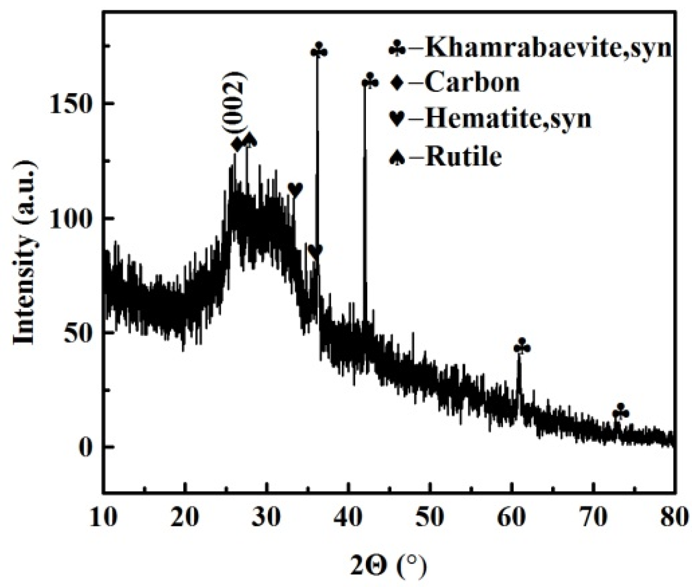
3.1. Characterization of FEBFS

The main chemical components of FEBFS samples were CaO, SiO2, Al2O3, and TiO2, followed by MgO and Fe2O3 (Table 1). The Cl content was 5.52%, slightly higher than the reported values of EBFS [8,9,15,36]. If the LOI of FEBFS was only composed of chlorine volatilization and carbon oxidation, the chlorine was nearly completely volatilized after burning. As a result, the carbon content of FEBFS was about 4.67%.
Figure 1 shows that the FEBFS samples contained crystalline phases and amorphous parts. The crystalline phases consisted of khamrabaevite, carbon, hematite, and rutile. The d002 value of graphitized carbon converted from coke is between 3.354 Å and 3.44 Å [37]. In comparison, the value of the carbon was 3.418 Å. Therefore, the carbon in FEBFS was classified as graphitized carbon. The particle size distribution of FEBFS samples is shown in Figure 2. The particle diameters were mainly concentrated in 10–90 μm, while the d (0.1), d (0.5), and d (0.9) were 5.852 μm, 32.07 μm, and 89.12 μm, respectively.

3.2. Effects of Flotation Conditions on the Flotation Performance

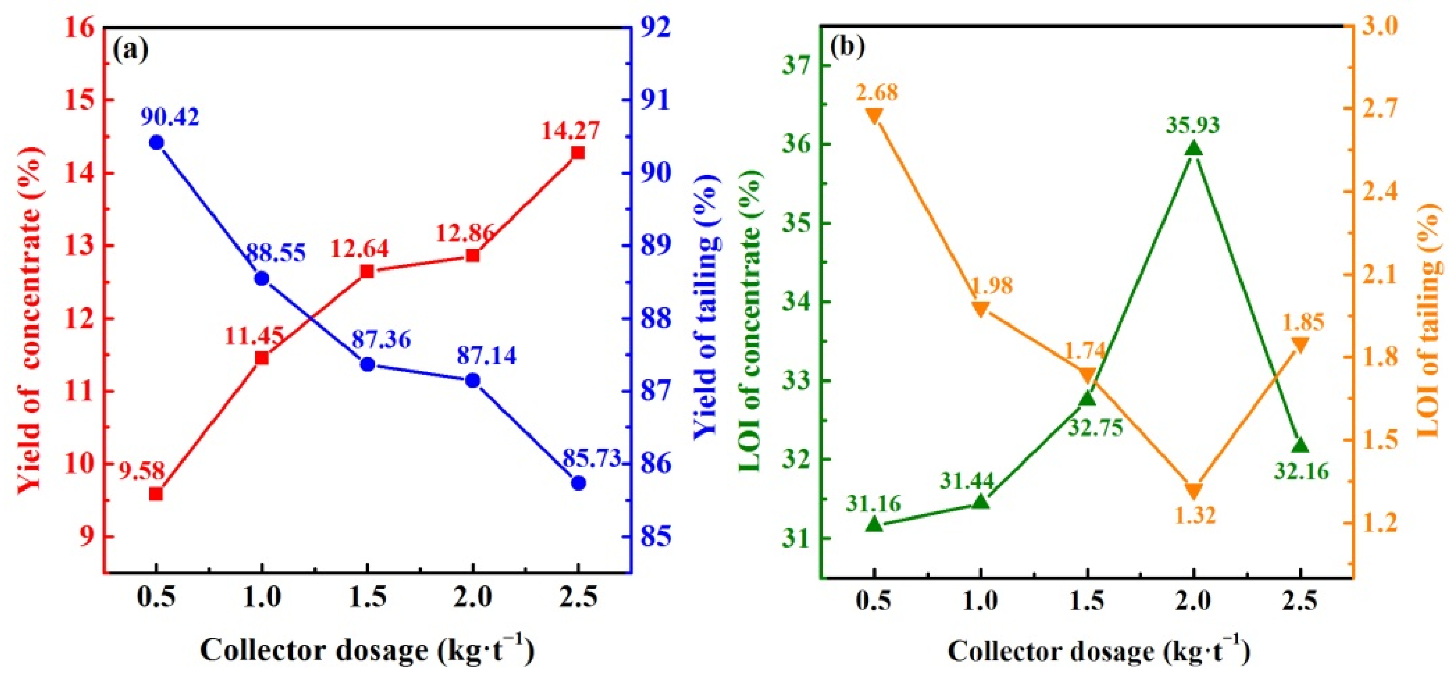
3.2.1. Collector Dosage

Kerosene is the prominent collector for the flotation recovery of residual carbon. Kerosene works on the surface of carbon grains. The surface tension of carbon grains decreases, and their hydrophobicity increases, which is conducive to the uplifting and recovery of residual carbon [38]. Kerosene was the collector with the dosage of 0.5–2.5 kg/t, and terpene oil was the frother with the dosage of 1.5 kg/t. The flotation steps and other experimental parameters were set as 2.2. With the increase in kerosene from 0.5 to 2.5 kg/t, concentrate yields continuously increased while their LOI first increased and then decreased, whereas the yields and LOI of tailings were the opposite (Figure 3). These results showed that kerosene captured the residual carbon of FEBFS samples, and the efficiency of carbon recovery could be improved by appropriately increasing the dosage of kerosene [23]. However, excessive kerosene counteracted the effect of the frother, resulting in reduced foam mobility, increased foam residence time, and the discharge of carbon particles from the foam to the slurry. As a result, the LOI of concentrate samples decreased, but those of tailings increased [38]. With a kerosene dosage of 2.0 kg/t, the LOI of concentrate reached the maximum 35.93%, and that of tailings dropped to the minimum 1.32%. It means the best flotation performance and the maximum carbon recovery efficiency occurred under this dosage. Therefore, the optimal collector dosage should be 2.0 kg/t.

3.2.2. Frother Types

The frother is necessary to adjust bubble size and enhance foam stability, thus improving flotation efficiency in froth flotation [39]. Terpene oil and sec-octanol are common frothers for carbon recovery in froth flotation [30,40,41,42]. Kerosene dosage was 2.0 kg/t, and terpene oil and sec-octanol were selected as frothers, and both were controlled at 1.5 kg/t. The effect of frother types on the recovery of residual carbon in the FEBFS samples was discussed. In Table 2, the LOI values of the flotation concentrate obtained from the two frothers were close. Nevertheless, the LOI of the flotation tailings produced by terpene oil was lower, indicating that terpene oil is more suitable for flotation recovery of residual carbon.

3.2.3. Frother Dosage

Following the determination of a suitable frother—terpene oil—we further discussed the effect of its dosage on the flotation performance. In Figure 4, with the increase in terpene oil dosage from 0.5 to 2.5 kg/t, concentrate yield kept increasing while tailings continuously decreased. The LOI of concentrate showed firstly increasing and then decreasing, while those of tailings had an opposite trend. It was shown that the appropriate dosage of terpene oil was beneficial to the recovery of residual carbon, while the excessive dosage inhibited it. Although the lowest LOI of flotation tailings was obtained at 2.0 kg/t terpene oil, the LOI of flotation concentrate was not desirable. Excessive terpene oil might interact with the hydrophobic group of the collector, resulting in a lower adsorption capacity of the collector on the carbon particles [30]. Some hydrophilic particles took the place of carbon grains and were recovered, which decreased the recovery efficiency of carbon residues. The appropriate dosage of terpene oil should be 1.5 kg/t.

3.3. Carbon Recovery and Dechlorination Efficiency

Based on the flotation performance under different conditions in 3.2, the optimized flotation conditions were as follows: kerosene as a collector with a dosage of 2.0 kg/t, terpene oil as frother with a dosage of 1.5 kg/t, and other experimental parameters were the same as 2.2. The OPFC and OPFT samples obtained under the optimized conditions were used to test and calculate the carbon recovery and dechlorination efficiency.
Compared with the Cl content of FEBFS (Table 1), those of the flotation samples were significantly reduced (Table 3). The dechlorination efficiency was calculated by Equation (2) to be 71.56%. Further, coupled with the yields and LOI of OPFC and OPFT samples, the carbon recovery was calculated by Equation (3) to be 84.79%. On the one hand, these results evidenced the recovery of the residual carbon and chlorine removal by flotation simultaneously. On the other hand, it was confirmed that most of the chlorine stored in EBFS was water-soluble, and the mechanical agitation could remove the water-soluble chlorine from the particle to achieve dechlorination.

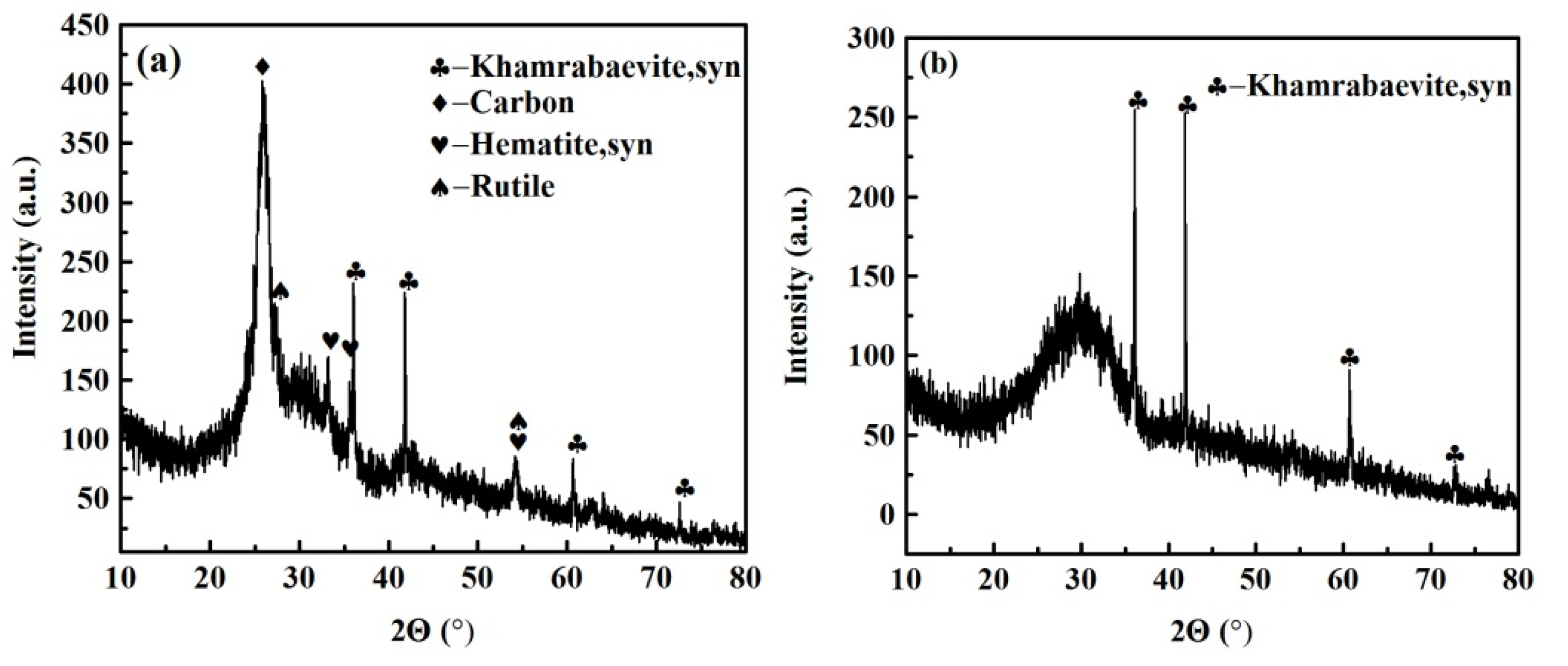
3.4. Phase Composition of Flotation Samples

Figure 5 shows the phase composition of the OPFC and OPFT samples. Compared with FEBFS, the intensity of the diffraction peak of the graphitized carbon (002) surface was significantly increased in OPFC, while there was no diffraction peak of graphitized carbon in OPFT. It indicated that the graphitized carbon could be effectively enriched and recovered by the designed flotation scheme. The presence of khamrabaevite in both samples implied that it was not selectively recovered. Khamrabaevite increased the viscosity of the molten slag and might be encapsulated in the carbonized slag after cooling, which makes it difficult to be selected and recovered [43]. Besides graphitized carbon and khamrabaevite, a small amount of hematite, rutile, and partly amorphous were also collected in OPFC. This indicated the presence of entrained impurities in the flotation process of residual carbon, which limited the improvement of the quality of flotation concentrate and carbon recovery. A large amount of amorphous phase was detected in the OPFT samples, with the yield up to 87.14%, indicating that most amorphous particles were retained in the tailings after flotation.

3.5. The Appearance of Flotation Feed and Products

The appearance of the flotation feedstock and products under the optimized conditions are shown in Figure 6. The FEBFS and OPFC samples were both black, but the OPFT samples were light brown. The residual carbon and slags were separated by froth flotation, giving different colors of flotation products. This result was determined by Guo et al. [25]. Therefore, we speculated that the residual carbon and tailings should be black and light brown, respectively. The residual carbon affected the color of flotation products. The concentrates with the high residual carbon content showed darker than tailings. Moreover, a sharp contrast in the appearance and color confirmed that most of the residual carbon was effectively recovered. Chlorine salts can absorb moisture from the air to build water bridges among powder particles and make them adhere together [44]. The Cl content was only 0.4% in OPFT, and the particle adhesion caused by the moisture absorption of chlorine was reduced to a shallow degree, which made the particle accumulation looser than in the other two samples.

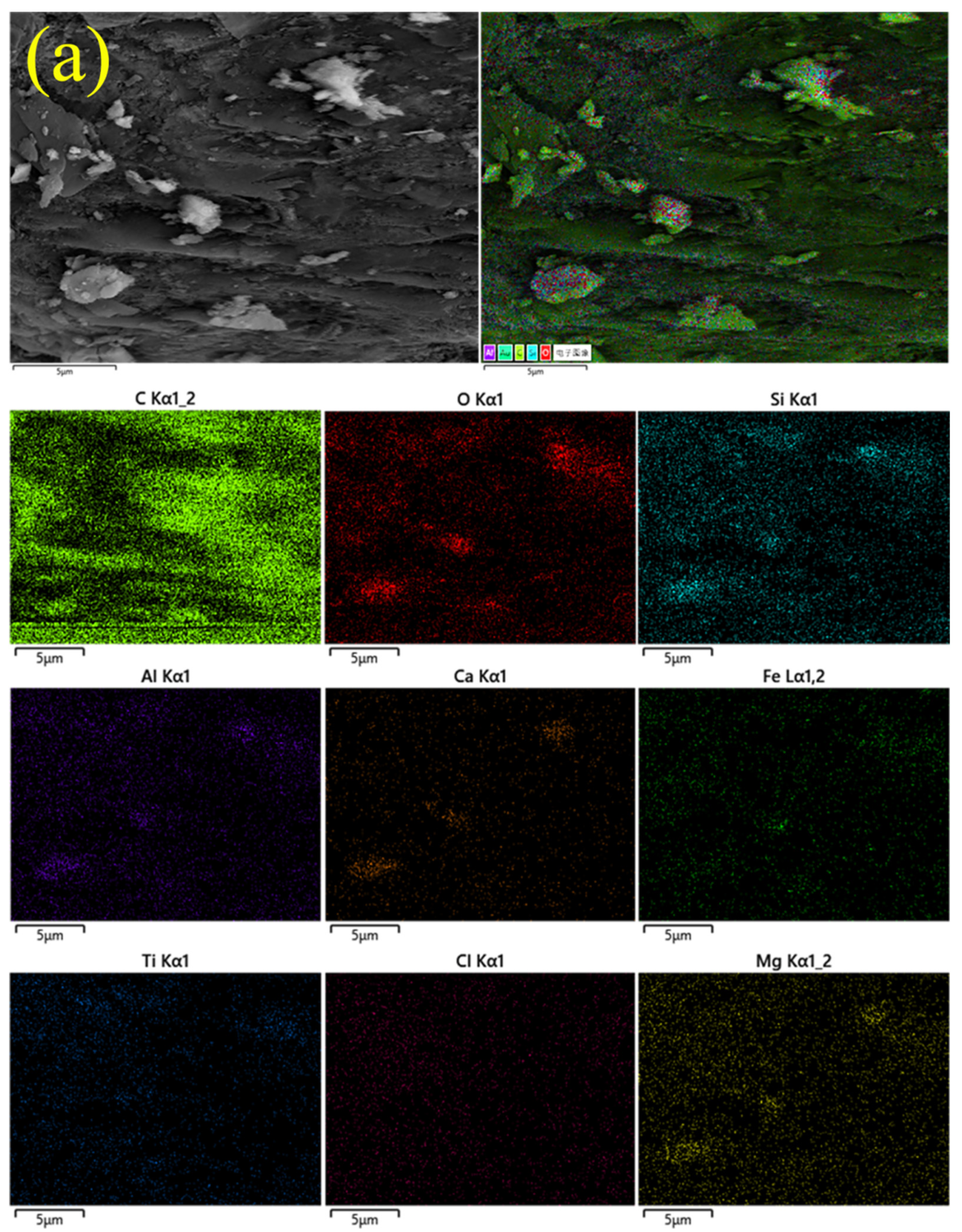
3.6. Microstructure and Elemental Distribution of Flotation Products

Figure 7 illustrates the microstructure of the flotation samples under the optimized conditions. Flakes with smooth surfaces and irregular-shaped particles can be observed in Figure 7a. These flakes were either embedded in the concentrate grains (point A) or stacked and covered on their surface (point B), while the particles were randomly scattered on the concentrate grains (point C). The flakes were not viewed directly in Figure 7b, but large numbers of irregular-shaped particles could be found, which were aggregated in the concaves of the large-sized tailing grains. With the analysis of XRD in 3.4, we believed that these flakes belonged to graphitized carbon, while the irregular-shaped particles were amorphous glasses. Kerosene has an excellent ability to trap hydrophobic flake graphite [45]. The trapped graphite particles are attracted to each other and form hydrophobic aggregates, and some hydrophilic impurities are wrapped in these aggregates, causing flotation entrainment [46]. As for the FEBFS samples, kerosene should selectively adsorb and act on the flaky graphitized carbon. The stacked and embedded graphitized carbon flakes were trapped and then clustered with each other, and the gaps among them became the landing places for the hydrophilic irregular particles. These particles float up to the foam layer associated with flakes, resulting in the entrainment of amorphous during the flotation.
The elemental distribution of flotation samples under the optimized conditions is shown in Figure 8. The abundance and content of the element could be reflected by the color and aggregation of the elemental spots in different areas of the element mapping. Brighter colors and more significant aggregations of spots indicate higher abundance and content of the element [47]. The areas where the flakes appeared in Figure 8a had a relatively high abundance of C elements in contrast to the other elements, which proved that the flakes were graphitized carbon. Meanwhile, the areas of the irregular-shaped particles had a relatively high abundance of O, Si, Ca, and Al elements, followed by Mg and Fe elements; nearly no C element existed, which confirmed that these particles belonged to amorphous aluminosilicate glass bodies.
Numerous irregular-shaped particles were gathered in the OPFT samples, and the abundance and contents of O, Si, Ca, Al, and Mg elements were significantly increased (Figure 8b), which supported Table 3. The Ti element mapping found a bright aggregation area of Ti element points (dashed yellow circle). Combined with the distribution of other elements, it was observed that only a few C elemental points were distributed in this area (solid blue circle), which indicated that khamrabaevite might exist here.
The Cl element points in the Cl element mapping of the OPFC samples exhibited a diffuse distribution and were hardly visible in the OPFT samples. On the one hand, it indicated that both samples had low Cl contents, especially the OPFT samples, which corresponded to the XRF results (Table 3). On the other hand, it further supported the recovery of residual carbon, and chlorine removal from EBFS could be accomplished simultaneously by froth flotation.

3.7. Contact Angles of Flotation Feedstock and Products

The contact angle of water droplets on the particle surface is to judge the hydrophobicity of the particle. The larger the contact angle, the stronger the hydrophobicity and floatability [48,49]. From Figure 9, the contact angles of OPFC, OPFT, and FEBFS samples were 32.83°, 17.84°, and 28.50°, respectively. The low contact angle values indicated they were poorly floatable and easily wetted by water. Combined with the phase composition, we found that graphitized carbon was essential to increase the contact angle and reduce the wettability.
Flotation separated the graphitized carbon and tailings, and most of the graphitized carbon was recovered to the OPFC sample and increased its contact angle. However, the contact angles of these samples changed a little before and after flotation. Several factors may influence the results of the contact angle. Besides the graphitized carbon, the OPFC samples contained some amorphous phases. The amorphous aluminosilicate glass bodies were hydrophilic, which would offset the hydrophobic enhancement by the graphitized carbon, causing the contact angle of OPFC samples to fail to be significantly improved [50]. In addition, the morphology of the carbon grains affects their water wettability. Spherical and flaky carbon grains with a smooth surface are hardly wetted as skeletal carbon grains with a rough surface and numerous grooves [48,51,52]. As for the OPFC samples, although the graphitized carbon was smooth flakes, some of them were embedded in the grains. The gaps among the flakes provided more room for the water droplet wetting carbon grains, leading to a low contact angle of OPFC samples. It is essential to mention that pressing the powder into disc changes its surface roughness, which is one factor that affects the contact angle measurement.

4. Conclusions

The carbon-containing phases were graphitized carbon and khamrabaevite in the FEBFS samples. The designed flotation scheme was mainly to separate and recover graphitized carbon, not khamrabaevite. After flotation, the intensity of the diffraction peak of graphitized carbon in the concentrate increased significantly, while no diffraction peak of graphitized carbon was present in the tailings. Some amorphous and other minerals appeared in the concentrate caused by flotation entrainment. Graphitized carbon showed smooth flakes, either embedded in or stacked on the surface of the concentrate grains. Amorphous particles were irregularly shaped, adversely affecting the quality, LOI, and hydrophobicity of the concentrate.
The appropriate flotation reagent dosage increased the yield and LOI of the concentrate, as well as reduced the LOI of the tailings. Terpene oil was more suitable to participate in the recovery of residual carbon as a frother than sec-octanol. Flotation allowed the recovery of graphitized carbon and the removal of chlorine simultaneously. With 2.0 kg/t of kerosene and 1.5 kg/t of terpene oil, the carbon recovery was 84.79% and dechlorination efficiency reached 71.56%.

Author Contributions

Funding acquisition, H.S.; project administration, H.S.; writing—original draft preparation, H.Y.; writing—review and editing, H.S.; methodology, T.P.; data curation, Y.Q. and S.T. All authors have read and agreed to the published version of the manuscript.

Funding

This research was funded by the Intellectual Property Special Project of Sichuan Intellectual Property Office, grant number 2022-ZS-00031.

Data Availability Statement

Not applicable.

Conflicts of Interest

The authors declare no conflict of interest.

References

  1. Lei, Y.; Sun, L.; Ma, W.; Ma, X.; Wu, J.; Li, S.; Morita, K. An approach to employ titanium-bearing blast-furnace slag to prepare Ti and Al–Si alloys. J. Alloy Compd. 2018, 769, 983–990. [Google Scholar] [CrossRef]
  2. He, S.; Sun, H.; Tan, D.; Peng, T. Recovery of Titanium Compounds from Ti-enriched Product of Alkali Melting Ti-bearing Blast Furnace Slag by Dilute Sulfuric Acid Leaching. Procedia Environ. Sci. 2016, 31, 977–984. [Google Scholar] [CrossRef]
  3. Han, J.; Zhang, J.; Zhang, J.; Chen, X.; Zhang, L.; Tu, G. Extraction of vanadium and enrichment of titanium from modified Ti-bearing blast furnace slag. Hydrometallurgy 2021, 201, 105577. [Google Scholar] [CrossRef]
  4. Zhang, L.; Zhang, L.N.; Wang, M.Y.; Lou, T.P.; Sui, Z.T.; Jang, J.S. Effect of perovskite phase precipitation on viscosity of Ti-bearing blast furnace slag under the dynamic oxidation condition. J. Non-Cryst. Solids 2006, 352, 123–129. [Google Scholar] [CrossRef]
  5. Zhang, W.; Zhang, L.; Li, Y.; Li, X. An environmental procedure to extract titanium components and metallic iron from Ti-bearing blast furnace slag. Green Processing Synth. 2015, 4, 307–316. [Google Scholar] [CrossRef]
  6. Shi, J.; Qiu, Y.; Yu, B.; Xie, X.; Dong, J.; Hou, C.; Li, J.; Liu, C. Titanium Extraction from Titania-Bearing Blast Furnace Slag: A Review. JOM 2022, 74, 654–667. [Google Scholar] [CrossRef]
  7. Zhang, S.; Zheng, K.; Jiang, J.; Zhang, S.; Xu, G. Effect of operating parameters on high-temperature selective enrichment and precipitation of titanium component in Ti-bearing blast furnace slag and the precipitation mechanism of perovskite. J. Mater. Res. Technol. 2021, 15, 2686–2696. [Google Scholar] [CrossRef]
  8. Chu, G.; Wang, L.; Liu, W.; Zhang, G.; Luo, D.; Wang, L.; Liang, B.; Li, C. Indirect mineral carbonation of chlorinated tailing derived from Ti-bearing blast-furnace slag coupled with simultaneous dechlorination and recovery of multiple value-added products. Greenh. Gases Sci. Technol. 2019, 9, 52–66. [Google Scholar] [CrossRef]
  9. Zhang, J.; Yan, Y.; Hu, Z. Preparation and characterization of foamed concrete with Ti-extracted residues and red gypsum. Constr. Build. Mater. 2018, 171, 109–119. [Google Scholar] [CrossRef]
  10. Zheng, F.; Li, M.; Wang, J.; Xi, C.; Fu, J.; Zhen, Q.; Jiao, Z.; Li, F.; Bashir, S.; Liu, J.L. Effective utilization of extracted titanium tailing to prepare high performance glass-ceramic and their formation mechanism. Ceram. Int. 2021, 47, 17391–17399. [Google Scholar] [CrossRef]
  11. You, H.; Sun, H.; Peng, T.; Li, Y.; Zeng, L.; Qin, Y. Effect of Sintering Time on Crystal and Structure of Chlorine-containing Low-titanium Slag Glass-ceramics. In IOP Conference Series: Earth and Environmental Science; IOP Publishing: Bristol, UK, 2020; Volume 615, p. 12124. [Google Scholar]
  12. Li, M.; Zhou, P.; Xiao, W.; Zhang, C.; Liu, Z. Study on preparation and performance of fluid loss additive applied to chlorination titanium blast furnace slag. J. Dispers. Sci. Technol. 2020, 42, 2163–2172. [Google Scholar] [CrossRef]
  13. Zhang, J.; Yan, Y.; Hu, Z.; Xie, X.; Yang, L. Properties and hydration behavior of Ti-extracted residues-red gypsum based cementitious materials. Constr. Build. Mater. 2019, 218, 610–617. [Google Scholar] [CrossRef]
  14. Long, P. Experimental Researches on Removal of Chloride in Blast Furnace Slag after Extracting Titanium. Iron Steel Vanadium Titan. 2014, 35, 42–45. (In Chinese) [Google Scholar]
  15. Li, L.; Jiang, T.; Chen, B.; Wen, J. Overall Utilization of Ti-Extraction Blast Furnace Slag as a Raw Building Material: Removal of Chlorine from Slag by Water Washing and Sintering. J. Sustain. Metall. 2021, 7, 1116–1127. [Google Scholar] [CrossRef]
  16. Quintanilla, P.; Neethling, S.J.; Brito-Parada, P.R. Modelling for froth flotation control: A review. Miner. Eng. 2021, 162, 106718. [Google Scholar] [CrossRef]
  17. Xing, Y.; Guo, F.; Xu, M.; Gui, X.; Li, H.; Li, G.; Xia, Y.; Han, H. Separation of unburned carbon from coal fly ash: A review. Powder Technol. 2019, 353, 372–384. [Google Scholar] [CrossRef]
  18. Li, H.; Wang, J.; Hou, W.; Li, M.; Cheng, B.; Feng, Y.; Xu, T. The Study of Carbon Recovery from Electrolysis Aluminum Carbon Dust by Froth Flotation. Metals 2021, 11, 145. [Google Scholar] [CrossRef]
  19. Cai, J.; Su, C.; Ma, Y.; Yu, X.; Peng, R.; Li, J.; Zhang, X.; Fang, J.; Shen, P.; Liu, D. Role of ammonium sulfate in sulfurization flotation of azurite: Inhibiting the formation of copper sulfide colloid and its mechanism. Int. J. Min. Sci. Technol. 2022, 32, 575–584. [Google Scholar] [CrossRef]
  20. Cai, J.; Shen, P.; Liu, D.; Zhang, X.; Fang, J.; Su, C.; Yu, X.; Li, J.; Wang, H. Growth of covellite crystal onto azurite surface during sulfurization and its response to flotation behavior. Int. J. Min. Sci. Technol. 2021, 31, 1003–1012. [Google Scholar] [CrossRef]
  21. Zhao, H.; Ruan, R.; Niu, X.; Li, L.; Zhang, E. A nanoscale qualitative study on the role of sodium hydrosulfide in oxidized carrollite flotation. Int. J. Min. Sci. Technol. 2021, 31, 1085–1093. [Google Scholar] [CrossRef]
  22. Blissett, R.S.; Rowson, N.A. A review of the multi-component utilisation of coal fly ash. Fuel 2012, 97, 1–23. [Google Scholar] [CrossRef]
  23. Zhang, W.; Honaker, R. Studies on carbon flotation from fly ash. Fuel Processing Technol. 2015, 139, 236–241. [Google Scholar] [CrossRef]
  24. Guo, F.; Zhao, X.; Guo, Y.; Zhang, Y.; Wu, J. Fractal analysis and pore structure of gasification fine slag and its flotation residual carbon. Colloids Surf. A Physicochem. Eng. Asp. 2020, 585, 124148. [Google Scholar] [CrossRef]
  25. Guo, F.; Miao, Z.; Guo, Z.; Li, J.; Zhang, Y.; Wu, J. Properties of flotation residual carbon from gasification fine slag. Fuel 2020, 267, 117043. [Google Scholar] [CrossRef]
  26. Liu, H.; Wei, G.; Zhang, R. Removal of carbon constituents from hospital solid waste incinerator fly ash by column flotation. Waste Manag. 2013, 33, 168–174. [Google Scholar] [CrossRef]
  27. Eisele, T.C.; Kawatra, S.K. Use of froth flotation to remove unburned carbon from fly ash. Miner. Processing Extr. Metall. Rev. 2002, 23, 1–10. [Google Scholar] [CrossRef]
  28. Walker, A.; Wheelock, T.D. Separation of Carbon from Fly Ash Using Froth Flotation. Coal Prep. 2006, 26, 235–250. [Google Scholar] [CrossRef]
  29. An, M.; Liao, Y.; Zhao, Y.; Li, X.; Lai, Q.; Liu, Z.; He, Y. Effect of frothers on removal of unburned carbon from coal fired power plant fly ash by froth flotation. Sep. Sci. Technol. 2018, 53, 535–543. [Google Scholar] [CrossRef]
  30. Yang, T.; Wang, N.; Gu, H.; Guo, T. Froth flotation separation of carbon from barium slag: Recycling of carbon and minimize the slag. Waste Manag. 2021, 120, 108–113. [Google Scholar] [CrossRef]
  31. Wang, S.; Xia, Q.; Xu, F. Investigation of collector mixtures on the flotation dynamics of low-rank coal. Fuel 2022, 327, 125171. [Google Scholar] [CrossRef]
  32. Liu, H.; Liu, F.; Wei, G.; Zhang, R.; Zang, D. Two-Step Flotation Treatment for Removal of Toxic Matter from Hospital Solid Waste Incinerator Fly Ash. Aerosol Air Qual. Res. 2017, 17, 1329–1340. [Google Scholar] [CrossRef]
  33. Liu, H.; Wei, G.; Zhang, R.; Liu, F. Simultaneous Removal of Heavy Metals and PCDD/Fs from Hospital Waste Incinerator Fly Ash by Flotation Assisted with Hydrochloric Acid. Sep. Sci. Technol. 2014, 49, 1019–1028. [Google Scholar] [CrossRef]
  34. Derya, O.; Sabina, K.; Huseyin, K. Recycling of coal combustion wastes. Waste Manag. Res. J. A Sustain. Circ. Econ. 2009, 27, 267–273. [Google Scholar]
  35. Zhou, F.; Yan, C.; Wang, H.; Zhou, S.; Liang, H. The result of surfactants on froth flotation of unburned carbon from coal fly ash. Fuel 2017, 190, 182–188. [Google Scholar] [CrossRef]
  36. He, S.; Peng, T.; Sun, H.; Luo, D.; Xiao, Q.; Geng, Q. Kinetics of Iron Removal From Ti-Extraction Blast Furnace Slag by Chlorination Calcination. Open Chem. 2019, 17, 1146–1156. [Google Scholar] [CrossRef]
  37. Gupta, S.; Sahajwalla, V.; Burgo, J.; Chaubal, P.; Youmans, T. Carbon Structure of Coke at High Temperatures and Its Influence on Coke Fines in Blast Furnace Dust. Metall. Mater. Trans. B 2005, 36, 385–394. [Google Scholar] [CrossRef]
  38. Huang, Y.; Takaoka, M.; Takeda, N. Removal of unburned carbon from municipal solid waste fly ash by column flotation. Waste Manag. 2003, 23, 307–313. [Google Scholar] [CrossRef]
  39. Cho, Y.S.; Laskowski, J.S. Effect of flotation frothers on bubble size and foam stability. Int. J. Miner. Processing 2002, 64, 69–80. [Google Scholar] [CrossRef]
  40. Yang, Z.; Chang, G.; Xia, Y.; He, Q.; Zeng, H.; Xing, Y.; Gui, X. Utilization of waste cooking oil for highly efficient recovery of unburned carbon from coal fly ash. J. Clean. Prod. 2021, 282, 124547. [Google Scholar] [CrossRef]
  41. Fan, G.; Zhang, M.; Peng, W.; Zhou, G.; Deng, L.; Chang, L.; Cao, Y.; Li, P. Clean products from coal gasification waste by flotation using waste engine oil as collector: Synergetic cleaner disposal of wastes. J. Clean. Prod. 2021, 286, 124943. [Google Scholar] [CrossRef]
  42. Qiu, Y.; Mao, Z.; Sun, K.; Zhang, L.; Qian, Y.; Lei, T.; Liang, W.; An, Y. Understanding the Entrainment Behavior of Gangue Minerals in Flake Graphite Flotation. Minerals 2022, 12, 1068. [Google Scholar] [CrossRef]
  43. Zhang, L.; Zhang, L.N.; Wang, M.Y.; Li, G.Q.; Sui, Z.T. Recovery of titanium compounds from molten Ti-bearing blast furnace slag under the dynamic oxidation condition. Miner. Eng. 2007, 20, 684–693. [Google Scholar] [CrossRef]
  44. Doh, H.; Lee, M.H.; Park, H.J. Investigation of the moisture-induced caking behavior with various dietary salts. J. Food Eng. 2019, 241, 67–74. [Google Scholar] [CrossRef]
  45. Tong, Z.; Liu, L.; Yuan, Z.; Liu, J.; Lu, J.; Li, L. The effect of comminution on surface roughness and wettability of graphite particles and their relation with flotation. Miner. Eng. 2021, 169, 106959. [Google Scholar] [CrossRef]
  46. Zhou, S.; Wang, X.; Bu, X.; Shao, H.; Hu, Y.; Alheshibri, M.; Li, B.; Ni, C.; Peng, Y.; Xie, G. Effects of emulsified kerosene nanodroplets on the entrainment of gangue materials and selectivity index in aphanitic graphite flotation. Miner. Eng. 2020, 158, 106592. [Google Scholar] [CrossRef]
  47. Pan, J.; Zhou, C.; Liu, C.; Tang, M.; Cao, S.; Hu, T.; Ji, W.; Luo, Y.; Wen, M.; Zhang, N. Modes of occurrence of rare earth elements in coal fly ash-a case study. Energy Fuels 2018, 32, 9738–9743. [Google Scholar] [CrossRef]
  48. Yang, L.; Li, D.; Zhang, L.; Yan, X.; Ran, J.; Wang, Y.; Zhang, H. On the utilization of waste fried oil as flotation collector to remove carbon from coal fly ash. Waste Manag. 2020, 113, 62–69. [Google Scholar] [CrossRef]
  49. Chen, S.; Tang, L.; Tao, X.; Chen, L.; Yang, Z.; Li, L. Effect of oxidation processing on the surface properties and floatability of Meizhiyou long-flame coal. Fuel 2017, 210, 177–186. [Google Scholar] [CrossRef]
  50. Suzuki, T.; Sekine, T.; Yamamoto, K.; Fukutani, K. Change in the surface OH group on soda lime silicate glass and silica glass after heat treatment in nitrogen atmosphere. J. Non-Cryst. Solids 2017, 464, 89–91. [Google Scholar] [CrossRef]
  51. Zhu, S.; Xu, L.; Yang, L.; Chen, X.; Lu, H. Effect of physicochemical properties of coal gasification fine ash on its wettability. Adv. Powder Technol. 2021, 32, 2123–2136. [Google Scholar] [CrossRef]
  52. Kang, W.; Li, H. Enhancement of flaky graphite cleaning by ultrasonic treatment. R. Soc. Open Sci. 2019, 6, 191160. [Google Scholar] [CrossRef] [PubMed] [Green Version]
Figure 1. XRD pattern of FEBFS samples.
Energies 15 06777 g001
Figure 2. Particle size distribution of FEBFS samples.
Energies 15 06777 g002
Figure 3. Effect of collector dosage on the flotation performance of FEBFS samples: (a) yield of flotation product and (b) LOI of flotation product.
Energies 15 06777 g003
Figure 4. Effect of frother dosage on the flotation performance of FEBFS samples. (a) yield of flotation product and (b) LOI of flotation product.
Energies 15 06777 g004
Figure 5. XRD patterns of flotation products were obtained under the optimized conditions. (a) OPFC samples and (b) OPFT samples.
Energies 15 06777 g005
Figure 6. The appearance of flotation feedstock and products. (a) FEBFS samples, (b) OPFC samples, and (c) OPFT samples.
Energies 15 06777 g006
Figure 7. SEM photos of flotation products. (a) OPFC samples and (b) OPFT samples, (A,B) flakes and (C) particles.
Energies 15 06777 g007
Figure 8. EDS photos and multiple element mappings of flotation products. (a) OPFC samples and (b) OPFT samples.
Energies 15 06777 g008aEnergies 15 06777 g008b
Figure 9. Contact angles of flotation products and feedstock. (a) OPFC samples, (b) OPFT samples, and (c) FEBFS samples.
Energies 15 06777 g009
Table 1. Chemical composition of FEBFS samples (%).
SampleCaOSiO2Al2O3TiO2MgOFe2O3ClOthersLOI
FEBFS28.5721.7912.0110.736.452.765.521.9810.19
Table 2. Effect of frother types on the flotation performance of FEBFS samples.
FrotherYield of Concentrate/%LOI of Concentrate/%Yield of Tailing/%LOI of Tailing/%
Terpene oil12.8635.9387.141.32
Sec-octanol4.4034.8195.603.11
Table 3. Chemical composition of OPFC and OPFT samples (%).
SampleCaOSiO2Al2O3TiO2MgOFe2O3ClOthersLOI
OPFC17.1515.838.849.524.435.061.172.0735.93
OPFT31.3027.1514.5913.067.602.150.402.431.32
Publisher’s Note: MDPI stays neutral with regard to jurisdictional claims in published maps and institutional affiliations.

