Article

Real-Time Simulation of a Small Modular Reactor in-the-Loop within Nuclear-Renewable Hybrid Energy Systems

by
Hossam A. Gabbar
1,2,* and
Otavio Lopes Alves Esteves
1
1
Faculty of Energy Systems and Nuclear Science, Ontario Tech University, 2000 Simcoe St. North, Oshawa, ON L1G0C5, Canada
2
Faculty of Engineering and Applied Science, Ontario Tech University, 2000 Simcoe St. North, Oshawa, ON L1G0C5, Canada
*
Author to whom correspondence should be addressed.
Energies 2022, 15(18), 6588; https://doi.org/10.3390/en15186588
Submission received: 7 August 2022 / Revised: 4 September 2022 / Accepted: 5 September 2022 / Published: 8 September 2022
(This article belongs to the Collection Energy Transition towards Carbon Neutrality)

Abstract

:
Advanced small modular reactors (SMRs) have recently been developed in many designs; therefore, nuclear energy stands out as a promising alternative to sustainability and reliability in replacing fossil fuel energies in microgrids. SMRs have been shown as the best option due to the fact of their lower initial capital, greater scalability, and siting flexibility compared to large nuclear plants. Nowadays, there are several simulators able to reproduce all the safety and control mechanics of different nuclear reactors; however, there exists a lack of emulators able to put these functionalities into a real scenario to ensure the feasibility of the use of nuclear energy within energy systems, especially in nonconventional systems. This paper aims to mimic the central control system of SMRs by modeling the nuclear processes aiming to contribute to real-time simulations using SMRs integrated with renewable energy in microgrids that could be applied for different scenarios, such as cogeneration systems or fast-charging stations for electric vehicles, by considering the impact on dispatch and reliability. The simulation process of the proposed model was validated experimentally using the hardware-in-the-loop technique, which consisted of the modeling being integrated into the hardware and tested using real-time simulators. The proposed system, also denominated as SMR-in-the-Loop, was designed and adapted to be easily integrated with existing microgrid systems to represent the behavior of an SMR in nuclear-renewable hybrid energy systems, avoiding high investments and complexity in testing and implementing actual nuclear reactors.

Graphical Abstract

1. Introduction

Over the last decades, it has become more evident that to measure the level of development of civilization, it is necessary to analyze how efficiently and sustainably electricity is generated. It is already evident that renewable energies are key to fighting climate change; therefore, it is a trend that must be part of all types of energy grids. However, these systems are considered to be intermittent sources due to the fact of their fluctuating nature and their dependency on external factors that cannot be controlled and their efficiency, which is highly influenced by the weather, resulting in problems of energy supply and continuity of service [1].
Renewable energy systems mostly need dispatchable generation to maintain stability. This is where nuclear energy stands out as a promising alternative in aiming for reliable and carbon-free electricity. Nuclear power plants (NPPs) can reduce greenhouse gas emissions and mitigate several other toxic air pollutants. Hence, NPPs can provide many benefits including fossil fuel replacement, renewable sources integration, and application with cogeneration systems [2].
Although researchers have shown the importance of nuclear energy in meeting the world’s increasing energy demand and mitigating the effects of global warming, the nuclear sector has slowed in growth over the last few years, mainly due to the fact of its low popularity resulting from the most worldwide known nuclear disasters, which resulted in large-scale nuclear plants falling out of favor with some governments and populations. The most well-known and socially influential nuclear accidents, namely, Three Mile Island, Chernobyl, and Fukushima, are the main reasons nuclear energy has a misconception among the population [3]. However, giving up this technology based on these events is a big mistake. They were improving technology, ensuring greater security and reliability, and taking advantage of the numerous benefits that nuclear energy can provide to humanity [4].
Although shreds of evidence show that nuclear energy is safer and more sustainable than fossil fuels, nuclear power corresponds to only 4% of the global energy mix. To reverse this scenario, new nuclear reactor technologies have begun to be developed to increase their security and reliability, emphasizing small modular reactors (SMRs). In accordance with the International Atomic Energy Agency (IAEA), small modular reactors (SMRs) are often used to describe nuclear reactors that can be built and assembled in a factory and then shipped to be installed on location [5].

1.1. Small Modular Reactors

Several nations are developing small modular reactors (SMRs) to incite the use of nuclear energy in the world’s energy matrix to meet future energy demands and environmental standards. These reactors aim for the deployment of innovative nuclear technologies in energy systems by providing advantages in the field of security, safety, and waste management; improved manufacturing techniques and installation logistics; adapting plant output to increase operating flexibility; efficient resource utilization and economy; flexibility in design, siting, and fuel cycle options; increased affordability [6].
Moreover, these developments seek to increase the accessibility of nuclear energy in markets where the use of a conventional nuclear power plant is unfeasible, in other words, to arouse nuclear energy investment in scenarios where nuclear energy is usually not an option such as in developing countries, microgrids, and energy systems with a lower rate of increase in demand for the replacement of fossil fuels as fuel sources.
One of the central promises of SMR technology is a reduction in the investment cost through modularization, which allows for the manufacture of these reactors on a large scale, which are built and assembled in a factory and then shipped to be installed at the location, reducing both the cost and time involved in its construction. Due to the lower initial price compared with a large NPP, it is expected that emergent nations will start to invest more in this technology [7]. In other words, standardization causes projects to take less time, and as they are modular, there is the possibility of starting with a smaller production and adding small reactors as needed. The project can start small and grow over time, unnecessary for the total initial investment. In addition, everything that reduces or at least dilutes the expense of a plant is essential for the survival of nuclear energy, since the investment cost is not one of its positive points.
Another potential application of SMR power production is integrating energy systems with a high share of renewable sources. As the most common renewable energy systems used currently, such as solar and wind, are highly dependent on the weather and, consequently, are intermittent, their use is only justified when integrated with a sustainable and dispatchable energy source, and this is where SMRs stand out as the best option in these scenarios.
The original concept of an SMR is defined based on the output nuclear power plant rate, typically less than 300 MW. However, these reactors provide a broad range of applications beyond the electrical system, possibly addressing partial or full thermal power to cogenerate applications, such as heating, hydrogen generation, and desalination. This possibility of using the capacity of a nuclear reactor in several applications results in a significant increase in the return on investment [6].
Nowadays, there is a wide range of SMR design concepts in different stages of development worldwide, and many types use different reactor designs, configurations, types of moderators, coolant systems, and fuel, resulting in unique designs. According to the International Atomic Energy Agency (IAEA), over 70 designs of SMRs are currently under development. Advanced reactors based on the concept of light water reactors (LWRs) are the most used SMR design, representing approximately half of the SMR concepts under development. The other half corresponds to reactors incorporating alternative coolants, such as molten salts and liquid metals, modern system configurations, and more effective fuels [8]. A summary of the main reactor designs under development is shown in Figure 1.
Another reason these reactors are more economically attractive is that each module can be replenished individually. In the case of conventional reactors, they must be turned off for weeks to cool down, and only then can they be filled. In addition, in the case of traditional reactors, the period of replenishment leads to economic loss, since during the entire time, the plant needs to be shut down, stopping the production of electricity. Finally, these SMRs are designed to be integrated into nonconventional energy systems, which means that nuclear energy will probably be used beyond the conventional baseload concept. However, these SMRs are not actually small and cheap enough to become economically feasible for installment in research centers or laboratories for simulation purposes [9].

1.2. Nuclear Power Plant Simulators

Numerous studies have analyzed the functioning and benefits of SMRs. It is becoming evident for the need of complex real-time simulation-embedded systems, discarding the need to implement an actual reactor for research and standards procedures. Currently, there are several simulators able to reproduce all the safety and control mechanics of different nuclear reactors, providing practical learning related to the engineering and physics of nuclear reactors. According to the International Atomic Energy Agency (IAEA), these simulators are currently available on the market for education and training [10] as shown in Table 1.
However, in addition to the comprehensive availability of simulators, there is still a lack of emulators able to put these functionalities into a real scenario to ensure the feasibility of the use of nuclear energy within energy systems, especially in nonconventional systems and, therefore, to simulate the behavior of an SMR in a hybrid microgrid with less outlay and complexity compared with actual testing reactors.

1.3. Load following—Modes of Nuclear Power Plant Operation
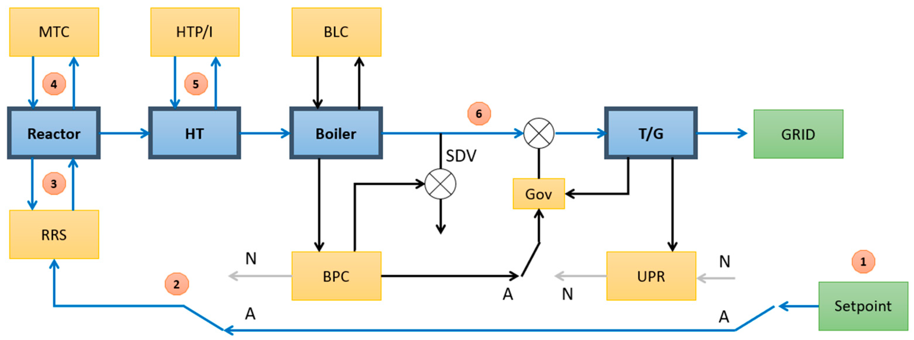
Due to the complexity, the lack of efficiency, and the risks in carrying out maneuvers in nuclear plants, NPPs have commonly been classified as baseload electricity generators over the last decades, which provide a constant energy supply to the load. However, this concept is beginning to change lately as a result of the increasing penetration of unstable energy sources into the electric grid, such as renewable sources, as well as the increasingly common microgrid with a high fluctuation of energy demand, which leads NPPs to operate with a variable output rate to follow the energy demand, known as the load-following technique. In addition, in nuclear reactors, this mode of operation typically works by reducing or increasing the reactivity in the core, which can be achieved using several methods, resulting in a variation in the thermonuclear power reduction [11].
Figure 2 shows a simplified control system concept of a nuclear power plant, which is composed of a reactor, a heat transport system (HT), a steam generator (boiler), and an electrical generator (T/G). In this figure, the blue boxes represent the NPP subsystem, while the yellow ones are the different control systems, which are explained in detail below [12].
Basically, there are two modes of operation in a nuclear power plant, namely, the normal and alternate modes. Their selection will depend on the actual scenario and the necessity of adjusting the output power. When a variation in the electrical demand occurs, the mismatch will provoke a frequency variation in the electrical grid. This fluctuation in the electric grid will be sensed by the turbine generator, which will change its speed aiming to meet the level and frequency of the energy demand.
In the normal mode, this change in the turbine speed will be reflected in the governor valve, adjusting the amount of steam directed to the turbine. The reactor’s regulating system then recognizes this steam level variation, which will activate regulation techniques to adapt the reactivity inside the reactor’s core according to the turbine generator. This mode is also known as reactor following or the turbine leading mode, since the turbine will define the output power, and the reactor will respond by changing the reactivity inside the core.
On the other hand, in the alternative mode of operation, the electrical output is defined first in the reactor core, and the turbine will change the output power according to the desired reactivity level. This mode is also known as reactor leading, since in this mode, the output in the turbine will reflect the reactivity in the reactor [13].
The following subsections explain the details of each load-following mode of operation.

1.3.1. Normal Mode

In this mode, the turbine leads the reactor, and the operation process occurs as follows, with the steps identified in Figure 3:
  • The desired value of the generator output is specified by the unit operator (setpoint);
  • The unit power regulator (UPR) reads the target value entered by the user (setpoint) and compares it with the actual generator output power (T/G);
  • According to the gap between the setpoint value and the output power, the turbine controller changes the opening of the governor valve (Gov) to control the amount of steam entering the turbine;
  • Changing the governor valve opening (Gov) also changes the pressure and water level inside the boiler. The boiler level control (BLC) ensures that the amount of water inside the boiler is at the desired level;
  • The boiler pressure control (BPC) is responsible for monitoring and controlling the boiler pressure by setting the steam discharge valve (SDV) opening;
  • The BPC also calculates the change in the reactor power setpoint and sends a command to the reactor regulating system (RRS) to compute the new setpoint value;
  • The RRS compares the demanded power setpoint request from the BPC with the current power of the reactor power and, according to the difference, changes it to the reactivity mechanism using the moderator temperature coefficient (MTC) to mitigate the power error;
  • The reactor power variation also affects the heat produced in the reactor’s core and, consequently, the amount of heat transferred (HT) to the steam generator;
  • The heat transport system’s pressure and inventory control (HTP/I) is responsible for controlling the heat transport pressure to maintain the pressure at a fixed setpoint (and in some reactors with a pressurizer, the pressurizer level is also controlled).

1.3.2. Alternate Mode

In this mode, the reactor leads the turbine, and the operation process occurs as follows, with the steps identified in Figure 4:
  • The desired value of the generator output is specified by the unit operator (setpoint);
  • The RRS compares the demanded power setpoint request by the user (setpoint) with the actual power of the reactor power;
  • According to the difference, the reactivity mechanism changes using the moderator temperature coefficient (MTC) to mitigate the power error;
  • The reactor power variation also affects the heat produced in the reactor’s core and, consequently, the amount of heat transferred (HT) to the steam generator;
  • The heat transport system pressure and inventory control (HTP/I) is responsible for controlling the heat transport pressure to maintain the pressure at a fixed setpoint (and in some reactors with a pressurizer, the pressurizer level is also controlled);
  • The steam from the boiler then drives the turbine according to the setpoint, resulting in the output power rate according to the desired value.

1.4. Modeling Nuclear Reactors

In the literature, several studies have analyzed the control systems of nuclear reactors. In [14], the authors developed a MATLAB/Simulink model for six groups of delayed neutrons with temperature reactivity feedback and different input reactivities. In [15], the author reduced the point kinetic equation of six groups of delayed neutron equations into one influential delayed neutron group and developed a Simulink model to solve it. This paper used this methodology to provide the total delayed neutron fraction and the decay constant for one group of delayed neutron precursors for four different nuclear fuels, namely, uranium-235, uranium-233, uranium-238, and plutonium-239. In [16], the author presented two other models of a PWR: a linearized and isolated core model and a nonlinear model for a nuclear system with U-tube steam generators. This was one of the research projects in the literature that motivated the development of this paper. For this paper, the desired power output rate was considered as a modeling input, which would control the reactivity and, consequently, the generation of energy either by the position of the control rods, the cold leg temperature, or the steam valve opening. Figure 5 shows the modeling schematic used in this paper.

2. Small Modular Reactor in the Loop

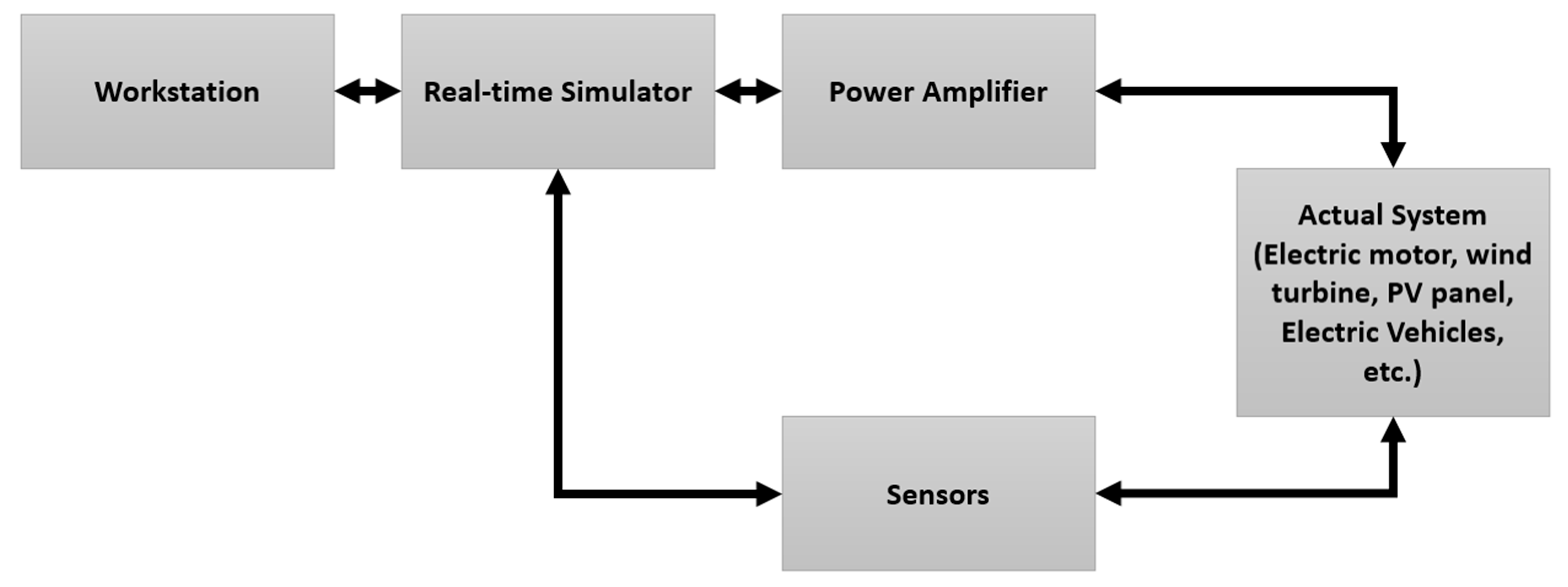
2.1. Hardware-in-the-Loop (HIL)

Hardware-in-the-loop (HIL) is a setup that allows for the interconnectivity of hardware and controllers with real-time simulators by emulating real-life conditions, reducing the complexity and cost compared to actual physical tests [17]. Hardware-in-the-loop consists of various virtual types of sensors, such as accelerometers or gyroscopes, and actuators, such as electric motors, turbines, and pumps, all connected to a central computer.
The HIL technique provides tremendous advantages for devices under development, because it avoids the necessity of the final physical product for performance testing, especially for devices where manufacturing requires a complex system, dangerous raw material, a costly and time-consuming process, and large equipment such that testing in laboratories becomes unfeasible [18]. Figure 6 shows the basic concept of an HIL system.

2.2. SMR-in-the-Loop (SMRiL)

The proposed SMR-in-the-loop, or SMRiL, was developed using the typical hardware-in-the-loop (HIL) technique, and it is used as part of the simulation environment to produce real-world scenarios for small modular reactors, aimed at increasing the efficiency of technology in energy grids. The main point of SMR-in-the-loop is to mimic the reactivity control devices of a reactor by considering real-world conditions and responding to unpredictable energy demands, in other words, using the device in a lab or a real energy microgrid to analyze this source’s effectiveness and reliability. Figure 7 exemplifies the schematic of an SMR-in-the-loop implementation.
In emulating different reactor designs and regulating systems to compare feasibility in microgrid scenarios, it is helpful to identify possible errors and complement existing research on the use of SMR in microgrids by testing critical techniques that are hard to try otherwise such as transmission line limitations, intermittency of other energy sources, unpredictable fluctuation of load profiles, testing of the actual efficiencies of the cogeneration processes, and integration with different networks (i.e., water, thermal, and electrical).
The proposed system was used to model and evaluate the behavior of power generation from a typical PWR by considering the normal mode of Load Following operating, in which the reactor will adjust its power output as energy demand fluctuates throughout the day by managing the opening of the governor valve in order to control the amount of steam entering the turbine, and consequently changing the output to the desired rate. The proposed model aims to contribute to real-time simulations using nuclear modeling to simulate SMRs integrated with renewable energy in microgrids that could be applied to different scenarios, such as cogeneration systems or fast-charging stations for electric vehicles, by considering the impact on dispatch and reliability. For the modeling and simulation, MATLAB Simulink software and Arduino hardware were used.

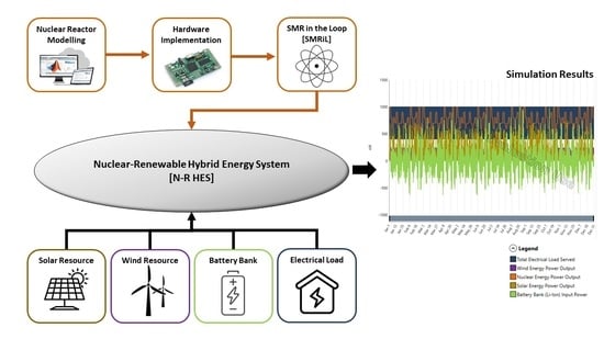
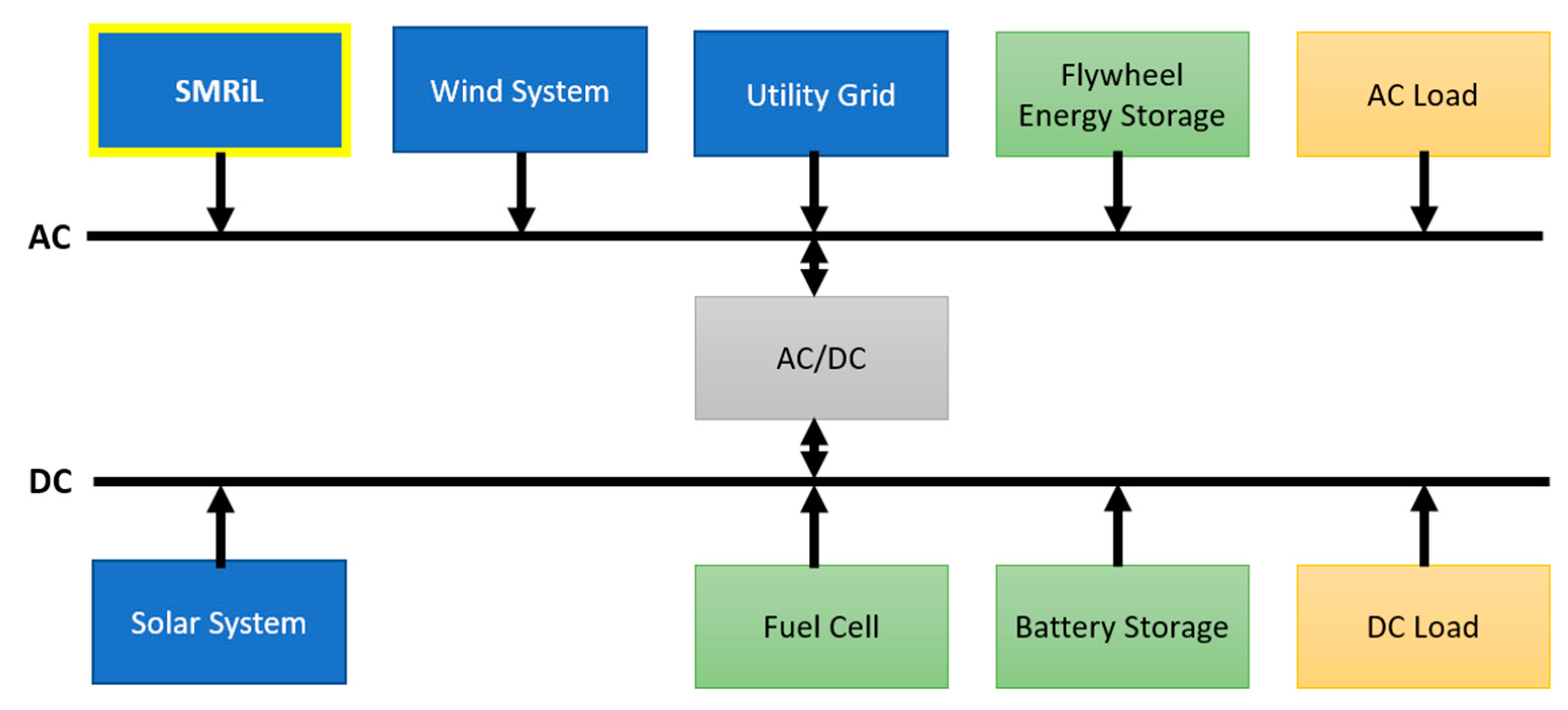
3. Nuclear-Renewable Hybrid Energy Systems

As mentioned before, using renewable sources and nuclear energy is essential to ensuring sustainability and energy resilience. However, there are disadvantages and risks associated with any energy source; while renewable is highly dependent on the weather and, consequently, intermittent, nuclear energy systems consist of a complex control system, and it is a time-consuming and expensive technology to be implemented [2].
Nuclear reactors provide a nonlinear output power when submitted to a power rate variation, making integration with a microgrid even more complex. The energy management system needs to address the response delay in stabilizing the output power, which uses alternative sources and energy storage systems to ensure the optical energy flow in the energy system.
The proposed SMRiL was developed to integrate this kind of hybrid energy system, and a real-time simulation was used to test the grid’s reliability under different conditions. Figure 8 illustrates a schematic of a hybrid energy system and the main components that could be integrated into the system, in which the blue boxes represent energy sources, green boxes represent energy storage systems, yellow boxes the energy loads, and the grey box the controller responsible for converting energy between alternate and direct current network. The main purpose of evaluating this hybrid system was to ensure its resiliency, regardless of the components of the system and environmental conditions; in other words, an effective hybrid system needs to be able to adapt itself in any possible scenario.

4. Modeling Nuclear Energy Systems

4.1. Reactor Specification

The reactor specification for this work was based on a typical pressurized water reactor (PWR), based on the H. B. Robinson Steam Electric Plant [19], consisting of a pressurized vessel, pressurizer, and three vertical U-tube steam generators with recirculation. The project considered constant values for a specific reactor design; however, this work aimed to provide an adaptable system that would evaluate any PWR reactor design. The reactor specifications used in this project are stated in Table 2.

4.2. Reactor Point Kinetic Equation
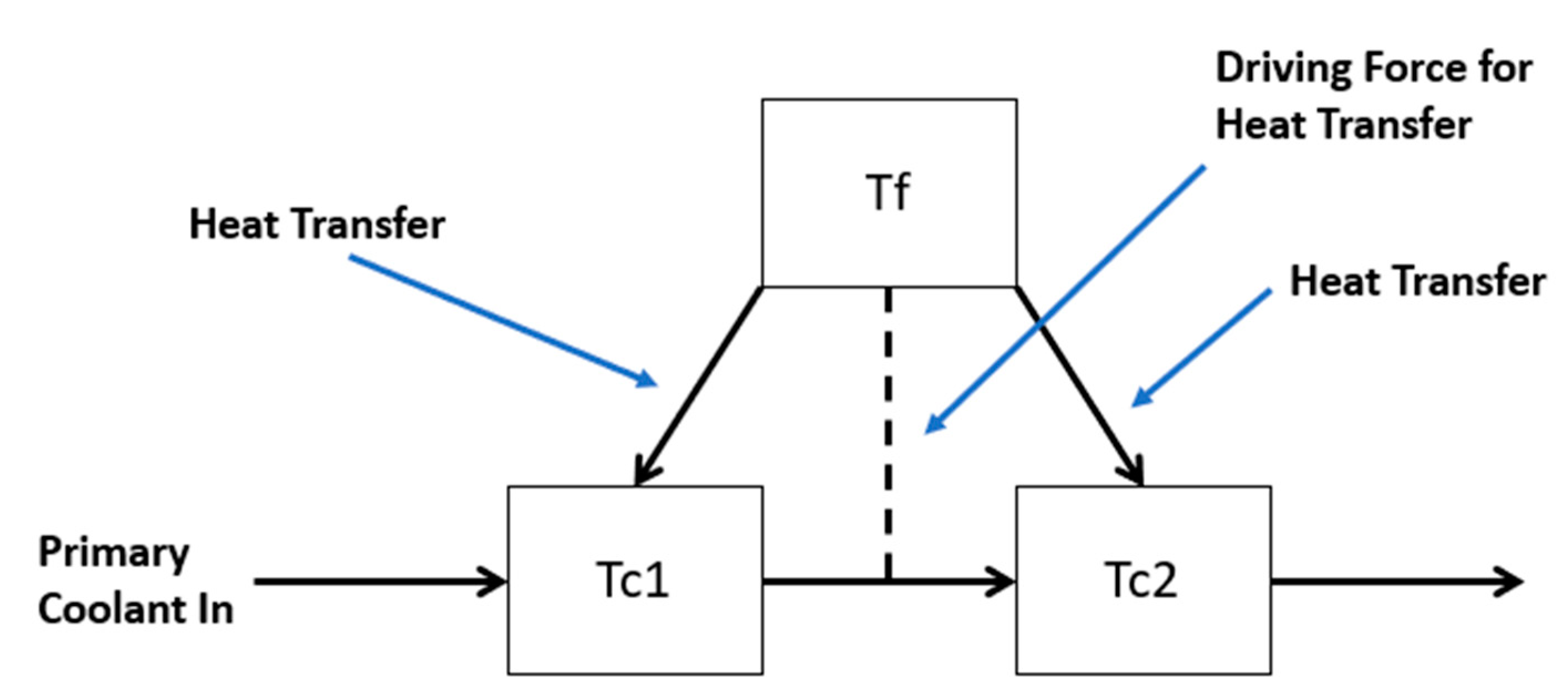
The number of neutrons in a nuclear reactor, which directly reflect the level of reactivity in the core, is a function of time, position, and energy. The neutron population changes in the reactor’s core according to the fission reaction of uranium or plutonium with a neutron from a previous generation. When the nuclear population increases in the reactor, the number of fissions increases, consequently increasing the reactor power. The same happens otherwise. However, the production of neutrons is not only by the prompt emerging from fission reactions but also by some neutrons whose fuel can produce a high concentration of neutrons that occasionally decay and release either beta particles or additional neutrons. These extra neutrons that come from decay are known as delayed neutrons.
With delayed neutrons, the neutron population in the reactor’s core increases, and this scenario directly affects the chain reaction. For this reason, it is essential to consider these delayed neutrons to have adequate reaction control. Engineers usually use the point kinetic equation to determine the neutron population, considering both prompt and delayed neutrons. Equations (1) and (2) reduce the reactor to a point, not considering the neutron flux’s shape and density distribution.
d n t d t = ρ t β Λ . n t + 1 6 λ i c i t
d c i t d t = β i Λ . n t λ i c i t
where n t is the neutron density, which is proportional to reactor power; ρ is the reactivity; c i is the i-th delayed neutron concentration; β is the effectively delayed neutron fraction; Λ is the prompt neutron generation time; λ i is the decay constant of the ith delayed neutron and c i is the fraction of the ith delayed neutron. This paper considered uranium-235 as a fissile material for the reactor core. Table 3 summarizes the typical values of the decay constant and the fraction of the six delayed neutrons for the materials used in this paper.
This paper used the Rashid [15] methodology, which reduced the point kinetic equation of the six groups of delayed neutron equations into one effective delayed neutron group. The decay constant and a fraction of the delayed neutron can be obtained by Equations (3) and (4), respectively.
β = 1 6 β i = 0.0064
λ = 1 β 1 6 β i λ i 1 = 0.0767

4.3. Reactor Core

For this project, data from H. B. Robinson Nuclear Plant was used, and the values for the coefficients were analyzed using the information in Table 3. The equations are described below. The reactor power was modeled using the point kinetics equations with six groups of delayed neutrons, and the reactivity feedbacks were the result of varying the fuel temperature, coolant temperature, and primary coolant system pressure. The following equations give the mathematical representation of the reactor core:
  • Deviations in the reactor power from the initial steady-state value (5):
d δ P d t = β Λ δ P + i λ i δ C i + α f P 0 Λ f u e l   n o d e s F f i δ T f i + α p P 0 Λ δ P p + P 0 Λ δ ρ r o d + α c P 0 Λ c o o l a n t   n o d e s F c i δ T c i
  • Deviation of the normalized precursor concentration from its steady-state value (6):
d δ C i d t = β i Λ δ P λ i δ C i
A nodal approximation to determine the temperature in the fuel and coolant was used in the heat transportation system in the reactor’s core, which included one node for the fuel temperature and two for coolant temperature to increase the value approximations. A schematic of the nodes is Figure 9.
The following equations provide a mathematical representation of each node:
  • Average fuel temperature (7):
d δ T f i d t = Q f i M C p f i δ P U A f M C p f i δ T f i δ T c 1 i
  • Average coolant temperature in the ith fuel node (8):
d δ T c 1 i d t = U A f M C p c i δ T f i δ T c 1 i 2 τ δ T c 1 i δ T c i n
  • Outlet coolant temperature in the ith fuel node (9):
d δ T c 2 i d t = U A f M C p c i δ T f i δ T c 1 i 2 τ δ T c 2 i δ T c 1 i

4.4. Pressurizer

A representation of the pressurizer is given by determining the energy and volume balance, as well as the mass in the pressurizer, which is reflected by the expansion of the water in the coolant nodes in the primary loop. The following equations provide a mathematical representation of the pressurizer:
  • Water flow in the pressurizer (10):
δ W w = i = 1 N V i γ i d δ T L P d t + V i γ i d δ T c 1 d t + V i γ i d δ T c 2 d t + V i γ i d δ T u p d t + V i γ i d δ T H L d t + V i γ i d δ T I P d t + V i γ i d δ T p d t + V i γ i d δ T O P d t + V i γ i d δ T C L d t
  • Pressure in the pressurizer (11):
d δ P p d t = B 1 δ P p + B 2 δ W w + B 3 δ q
  • Integral control action (12):
d δ X d t = 0.00556 δ P p

4.5. Steam Generator

The modeling proposed in this work used a simple steam generator schematic represented by three different subsystems: the primary fluid, the secondary fluid, and the tube metal. This paper also considered the steam generator without a control action, assuming that the design proposed will be applied only for small perturbations so that the controller dead-band will avoid variations in the feedwater flow.
The following equations give a mathematical representation of the steam generator:
  • Primary water–energy balance (13):
d δ T p d t = 1 T S G δ T I P h A p m M P C P δ T p δ T m 1 T S G δ T P
  • Metal energy balance (14):
d δ T m d t = h A p m M m C m δ T p δ T m h A m s M m C m δ T m δ T s a t δ P s δ P s
  • Steam generation pressure (15):
d δ P s d t = D 1 δ P s + D 2 δ T m + D 3 δ T F W + D 4 δ W F W + D 5 δ W s 0

4.6. Piping

For this work, two piping systems for the hot and cold leg and four plenums for the steam generator input and output, and the upper and lower reactor were considered. It was also considered that the piping and plenums system had mixed volumes, and the following equation gives the temperature in the output and input sections:
  • Piping temperature (16):
d δ T d t = 1 τ δ T i n 1 τ δ T

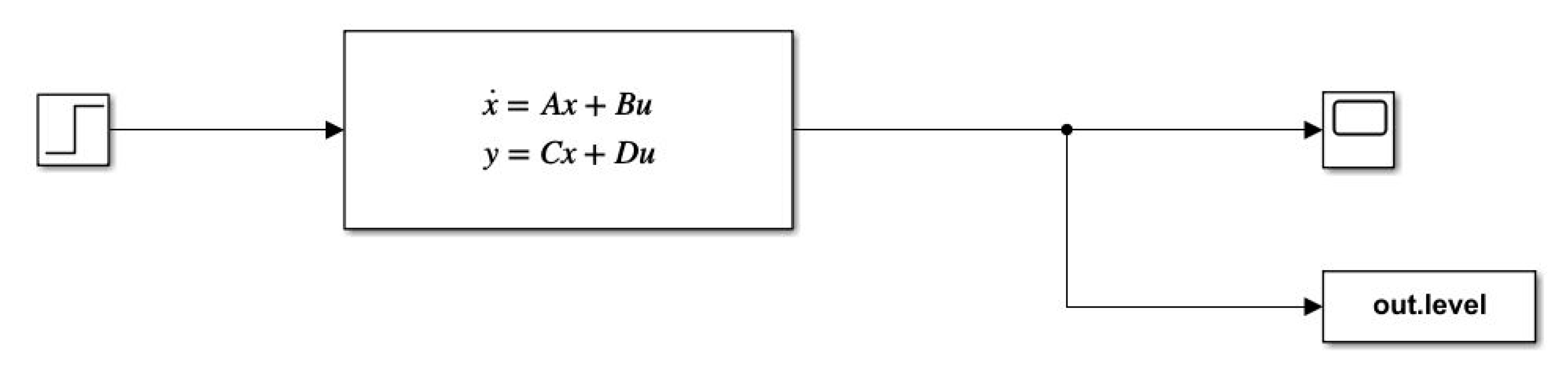
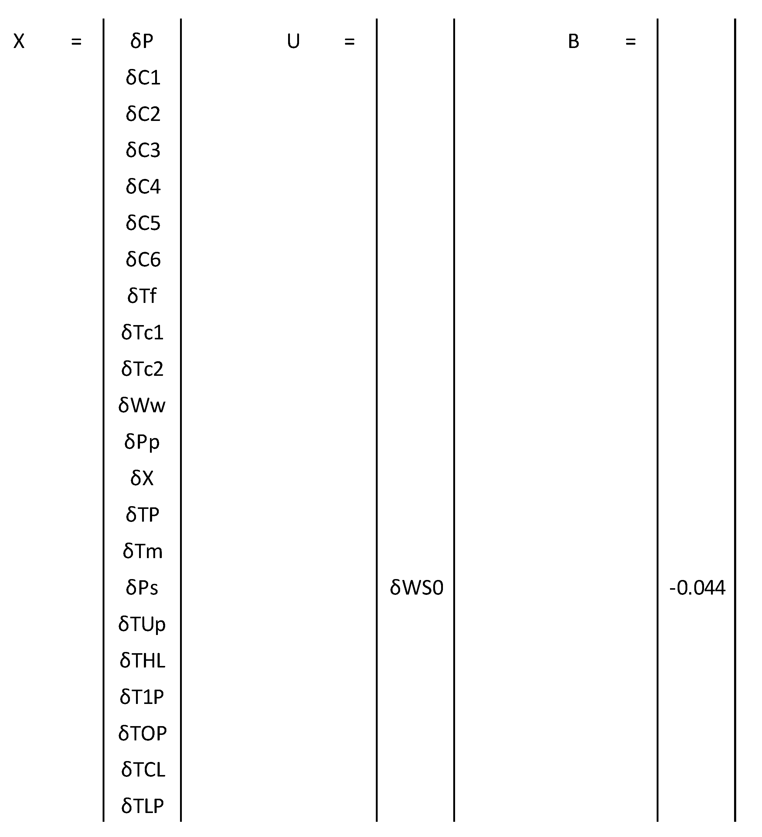
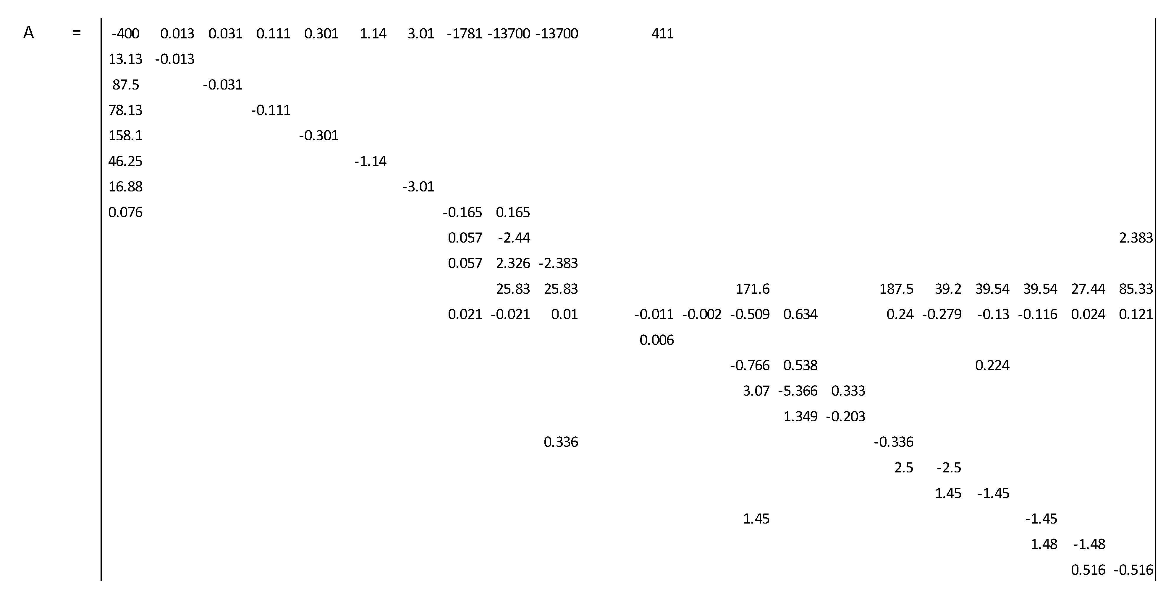
4.7. State-Space Representation of the Dynamic Equations

State-space is a calculation approach that arranges a multivariable system that contains several inputs, outputs, and state variables. These equations can be described as first-order differential equations [20]. The mathematical representation of the system is described in Equations (17) and (18), where A is the state matrix, B is the input matrix, C is the output matrix, D is the direct transmission matrix, X is the vector of state variables, and U is the external input vector.
d X _ d t = A X _ + B U _
y = C X _ + D U _
Figure 10 shows a schematic using MATLAB/Simulink that simplifies the state-space system calculation.
To solve Equations (5)–(16), it was necessary to determine the matrixes of each group. The matrix X is the system matrix, representing the variables in the proposed system, matrix U is the input variable matrix, the steam flow rate to the turbine, and matrix B is the constant correspondent to the input variable. The matrixes X, U, and B, are presented in Figure 11.
The matrixes A represent the constants of each equation related to the output variables, and it is presented in Figure 12.

5. SMRiL Modeling

For this study, MATLAB/Simulink were used to ease the calculation of the state-space representation and to perform the time response of the system as well as to create a subsystem aimed at hardware integration to develop the SMR-in-the-loop and test the system considering actual scenarios in a nuclear-renewable hybrid microgrid. Figure 13 shows the complete Simulink schematic.
Figure 14 states the input system, which inserts the desired power rate according to a signal from either the energy management or a user interface. The system calculates the correspondent steam valve opening to achieve the desired output power.
Figure 15 states the output system, which generates the output reactor power through the state-space system based on the input system.
The schematic was combined into a Simulink block, as shown in Figure 16, to facilitate hardware integration and use in real-time simulators such as OPAL-RT. The schematic was designed to provide the reactor with nominal power and the desired output power rate as a system input.
To evaluate the behavior of power generation from a nuclear reactor, the output response was simulated using a desired power rate of 50% of the full power as the signal input. Figure 17 shows the corresponding output curve, which can analyze the system’s behavior and time response to stabilize the output power at the desired value, which was approximately 150 s after inserting the input signal. This time response is crucial for evaluating the integration of NPPs with renewable and inconsistent demand profiles, where the nuclear control system needs to variate the output to ensure the energy supply.

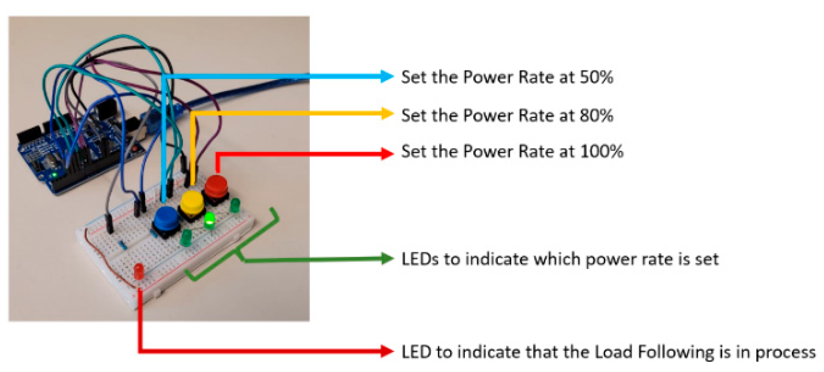
Hardware Integration

The main point of this research was to develop an SMR-in-the-loop, which consisted of a real-time simulator using the HIL method to mimic the behavior of nuclear reactors using existing electrical and thermal networks as well as signal input from a real-time scenario. For this, all the mathematical modeling presented in this paper was integrated into the hardware, Arduino UNO, aimed at achieving the interconnection flexibility of the system proposed with actual energy networks.
Hardware integration is important for enabling the system to mimic the output power from a reactor by controlling energy sources according to the mathematical modeling. In addition, hardware integration aims to develop a physical device that can be used in different environments, either in lab research or in local experiments, which would not be possible using only computer programming. Figure 18 shows the setup of the hardware used in this project, where the user can set three different power rates to analyze the performance, with output as a PWM signal to be sent to the energy management and integrated with the nuclear-renewable hybrid energy system.
Figure 19 shows the correspondent output curve, which can analyze the system’s behavior and time response to stabilize the output power at the desired value, which was approximately 150 s after inserting the input signal. This time response is crucial for evaluating the integration of an NPP with renewable and inconsistent demand profiles, where the nuclear control system needs to variate the output to ensure the energy supply.

6. SMRiL Demonstration and Results

To demonstrate the functionalities of the proposed SMR-in-the-loop, the normal mode technique of load following was used, as stated in Section 1.3, where the turbine generator was synchronized with the grid and, depending on the electric load, a mismatch would occur; consequently, the grid frequency would also change. Consequently, with the change in the pressure of the steam line, the reactor will change the reactivity inside the core to maintain the system’s stability at a desired power rate.

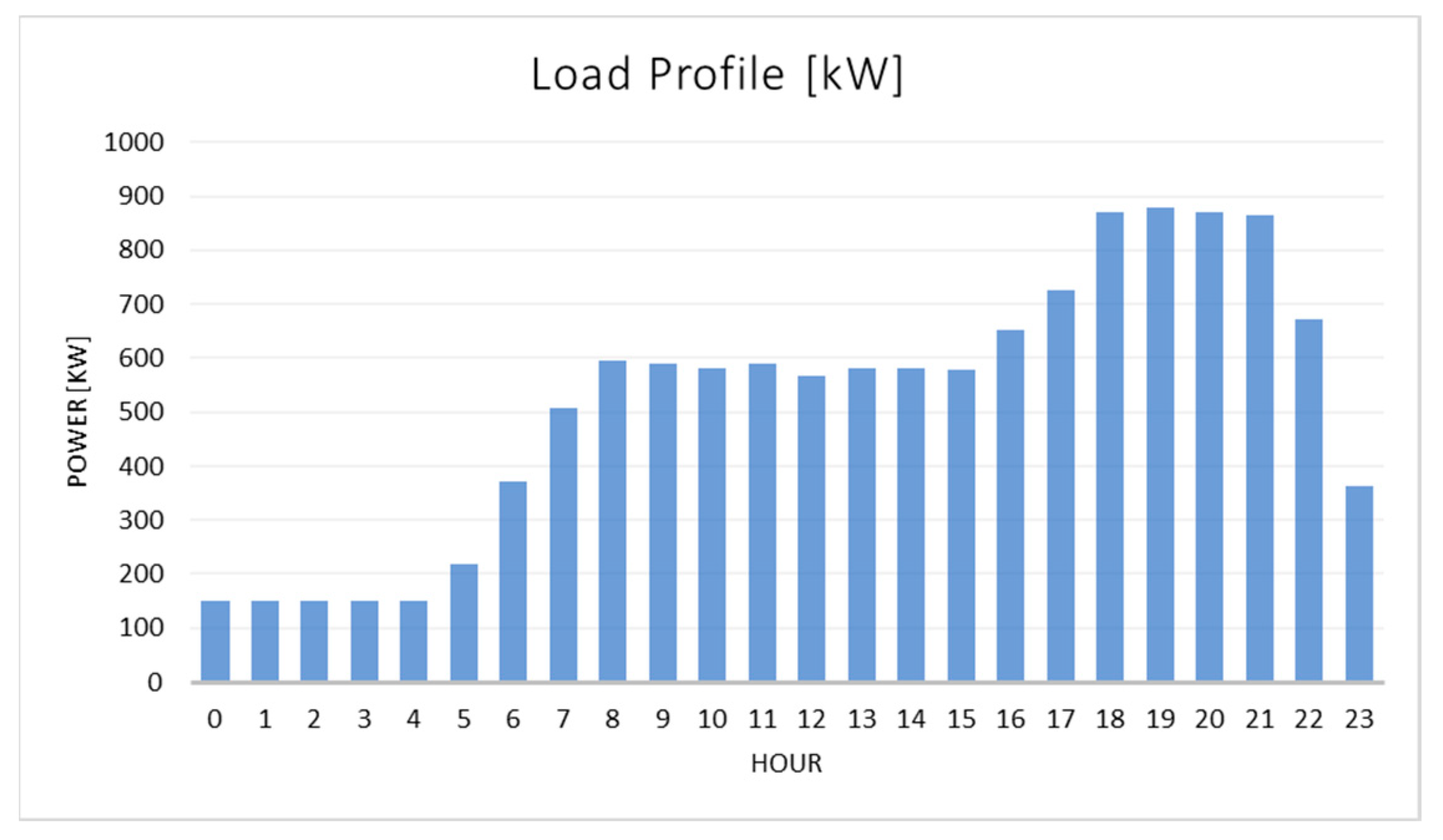
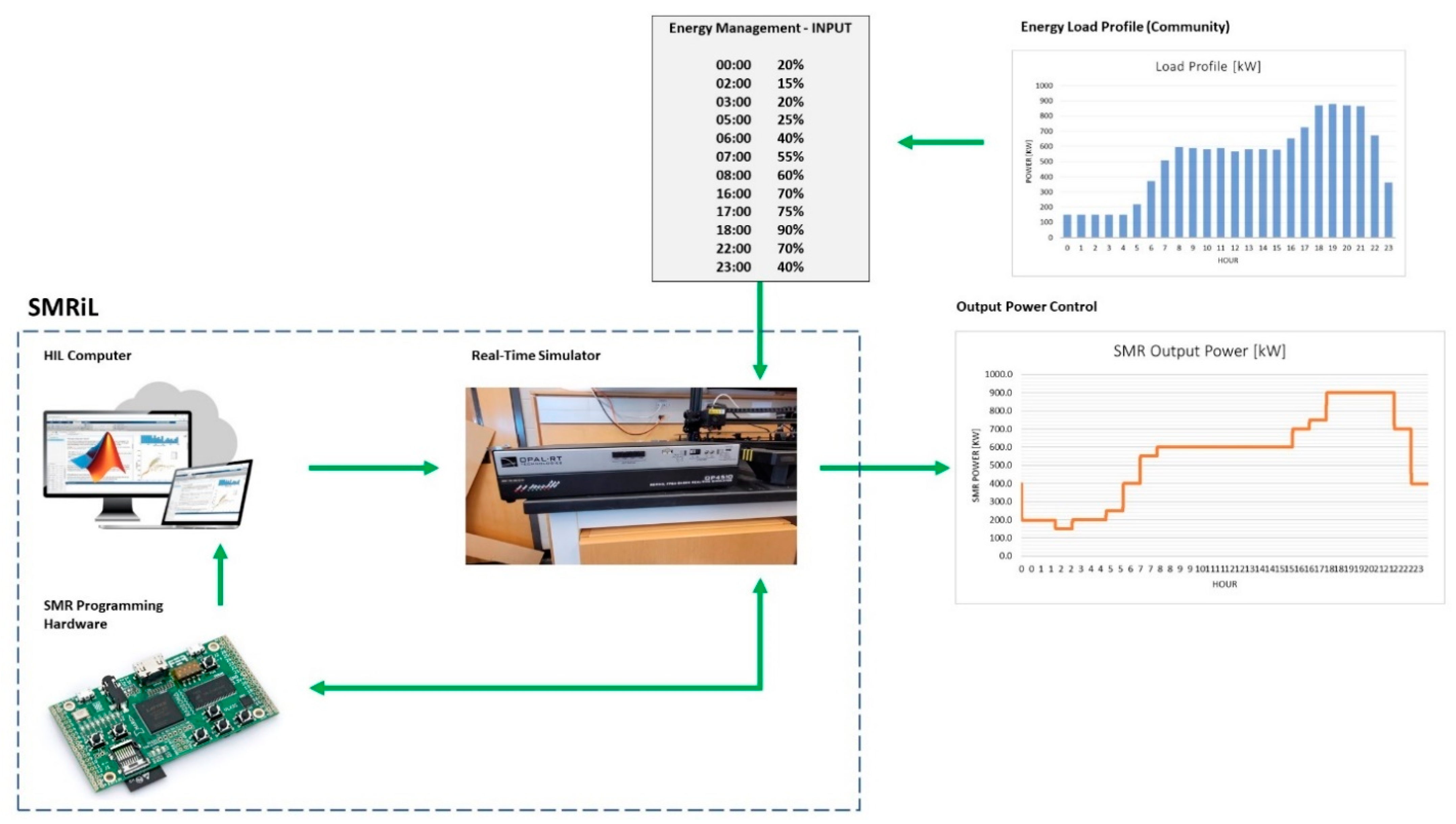
6.1. Energy Profile and Management

To simulate an electrical demand to be integrated into the system, a hypothetical energy load was considered to serve as a base for the energy management to define the desired power rates that the SMR needs to provide to achieve grid stability. Figure 20 shows the typical daily energy consumption used in this demonstration.
The energy load will be read by the energy management system, which will translate the energy demand in the signal input for the SMR-in-the-loop system. The data input is summarized in Table 4.

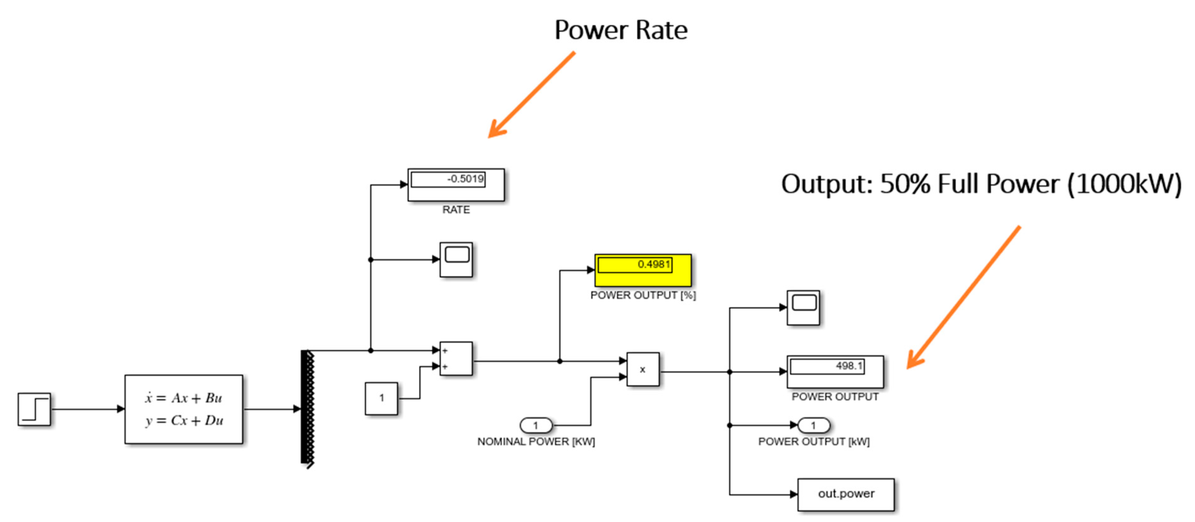
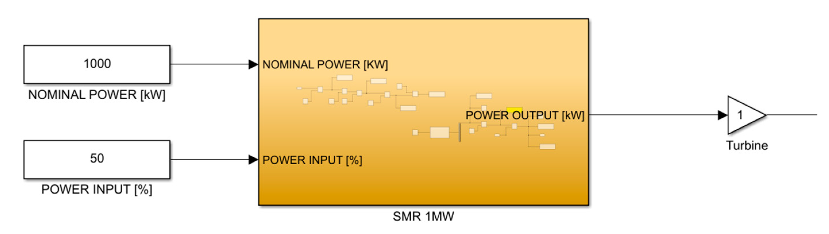
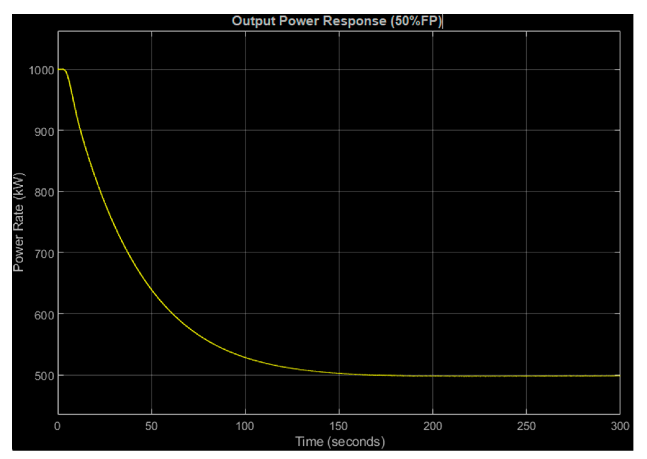
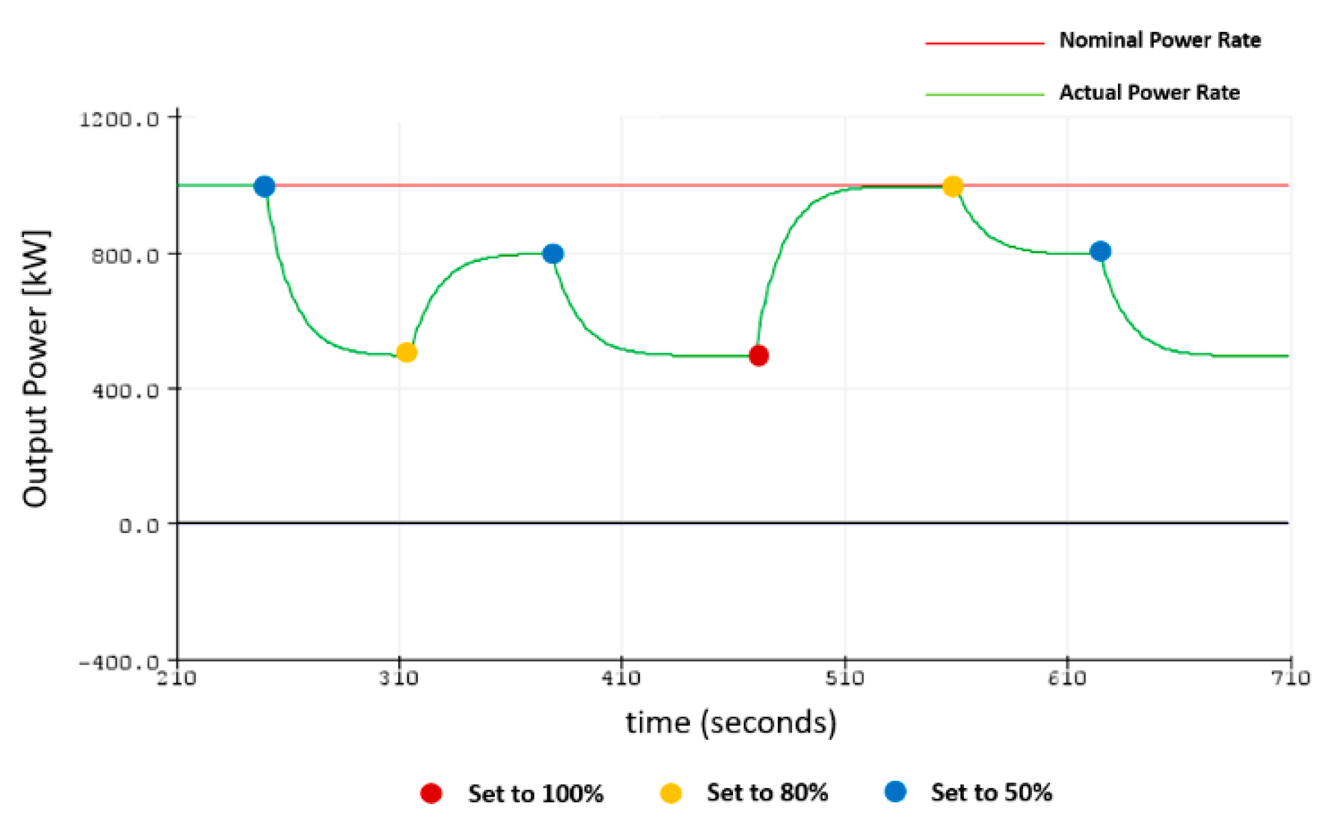
6.2. SMRiL—Output Power Control

Figure 21 shows the entire schematic of the SMR-in-the-loop, in which the energy management system is responsible for monitoring the grid in defining the desired power rate to keep the electrical grid stable. The real-time simulator, in turn, receives the information from the energy management to feed the hardware-in-the-loop system. Consequently, the system will respond to the input by varying the output power rate according to the desired power level throughout the day.

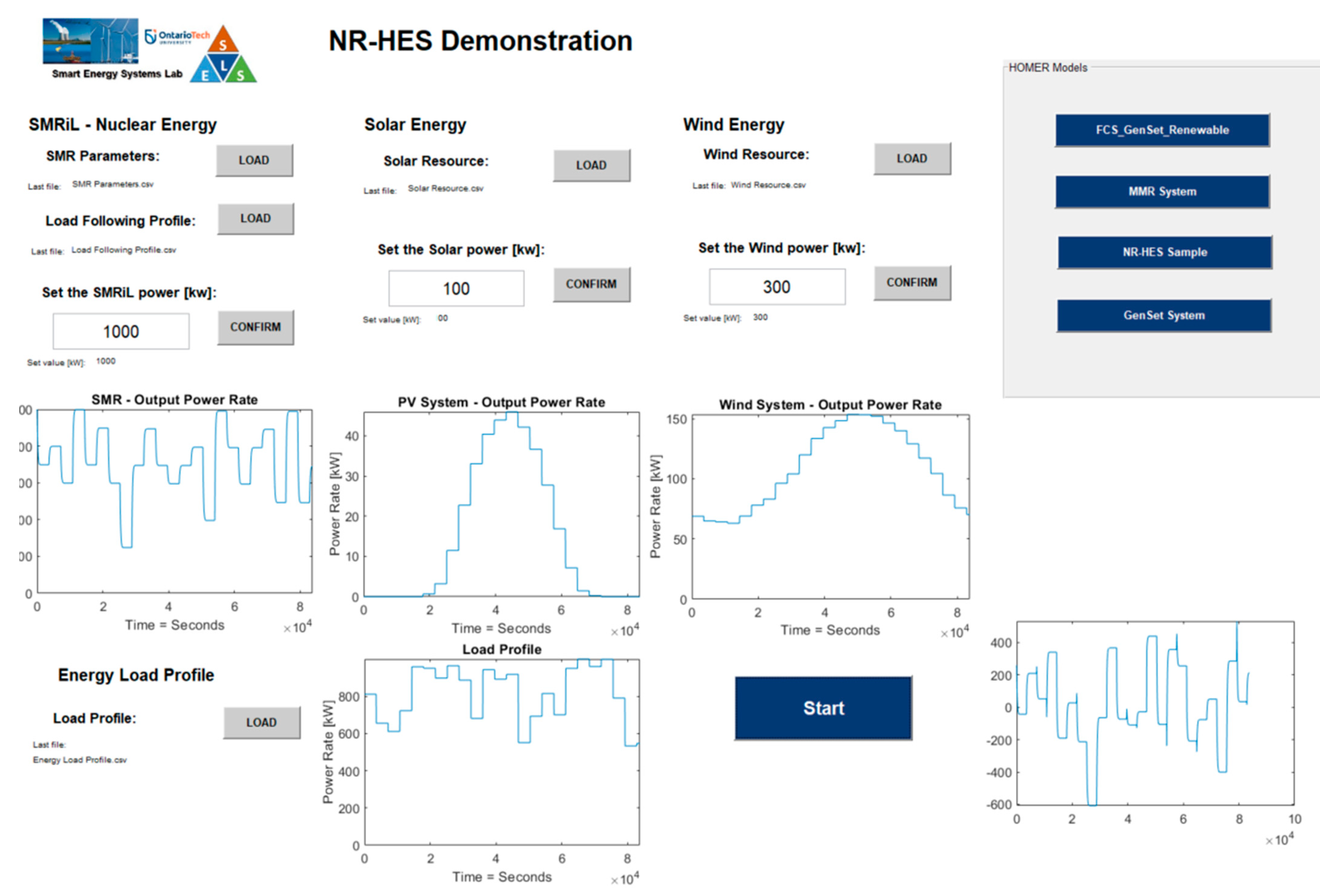
7. Hybrid Energy System Demonstration

To make possible the interaction and evaluation of nuclear-renewable hybrid energy systems, this paper developed a friendly user interface using MATLAB-GUI, which is able to define the nuclear parameters from the SMRiL and also set renewable parameters, such as the maximum power rate desired from the solar and wind energy as well as the energy load profile, as shown in Figure 22.
The input inserted in the user interface was used to simulate a viable system for all possible combinations considering the output profile from the nuclear modeling as well as the maximum power rate of each renewable source, which analyzed the best suitable solution for the set design.
Figure 23 shows the nuclear output from the SMR modeling according to the energy load profile inserted by the user, and Figure 24 shows the energy flow profile from the integration of the nuclear-renewable hybrid energy system.

8. Conclusions

Over the last years, the necessity of ensuring the flexibility of energy grids has become more inevitable, mainly due to the movement towards replacing existing fossil fuel systems with no-carbon emission sources, which will result in an increasing in the use of renewable energy sources and the share of nuclear energy in the energy mix. This scenario is changing the concept that nuclear energy is used only for baseloads, and the load-following technique will become more frequent in nuclear power plants.
Even though there are several simulators able to reproduce all the safety and control mechanics of different nuclear reactors; however, there is still exists a lack of emulators able to put these functionalities into a real scenario to ensure the feasibility of the use of nuclear energy within energy systems, especially in nonconventional systems.
Several studies found in the literature regarding nuclear and renewable energy systems integration wrongly considered the assumption that the nuclear load-following technique behavior has an instant and linear response, and this is especially since there is a lack of software able to simulate nuclear energy in a microgrid. For this reason, this paper was essential for evaluating the behavior of nuclear power plants when submitted by different perturbations, which are a mechanism used to vary NPP output power for load following. As shown in Figure 15, a nuclear power plant takes some time to stabilize the output power. This delay in response is fundamental in evaluating the feasibility of using nuclear energy in hybrid microgrids. Moreover, this study will benefit from integrating nuclear-renewable energy systems where resilience is the main point, and the control of nuclear reactors must be effective.
As mentioned in Section 3, this research focused on developing an integrated and adaptive small modular reactor (SMR) model to represent different reactor designs and all the main functions to perform a load-following technique for integration within hybrid energy systems (HES) by analyzing existing models and identifying new features, aiming to evaluate reactor behaviors when exposed to different perturbations.
For further studies, it should be considered to include a customizable mathematical model where the user will be able to set the parameters of a nuclear plant and choose the technology and adopted design. The main idea of this customizable mathematical model is to make it possible to simulate the behavior of different nuclear reactors when exposed to various perturbations.

Author Contributions

Conceptualization, All; methodology, All; software, All; validation, All; formal analysis, All; investigation, All; resources, All; data curation, All; writing original draft preparation, All; writing—review and editing, All; visualization, All; supervision, H.A.G.; funding acquisition, H.A.G. All authors have read and agreed to the published version of the manuscript.

Funding

This research was funded by NSERC grant number [210320].

Conflicts of Interest

The authors declare no conflict of interest.

References

  1. IAEA. Non-Baseload Operation in Nuclear Power Plants: Load following and Frequency Control Modes of Flexible Operation; International Atomic Energy Agency: Vienna, Austria, 2018. [Google Scholar]
  2. Suman, S. Hybrid nuclear-renewable energy systems: A review. J. Clean. Prod. 2018, 181, 166–177. [Google Scholar] [CrossRef]
  3. Kan, N. The Fukushima Nuclear Power Plant Disaster and the Future of Renewable Energy; Cornell University Press: Ithaca, NY, USA, 2018. [Google Scholar]
  4. Elliott, D. Does Nuclear Power Have a Place in a Sustainable Energy Future? In Nuclear or Not? Palgrave Macmillan: London, UK, 2007. [Google Scholar]
  5. Krikorian, S. IAEA Department of Nuclear Energy. 18 September 2019. Available online: https://www.iaea.org/newscenter/news/nuclear-and-renewables-playing-complementary-roles-in-hybrid-energy-systems (accessed on 5 April 2022).
  6. NEA. Small Modular Reactors: Challenges and Opportunities. Nuclear Energy Agency. Available online: https://www.oecd-nea.org/jcms/pl_57979/small-modular-reactors-challenges-and-opportunities?details=true (accessed on 16 April 2022).
  7. Morales Pedraza, J. Small Modular Reactors for Electricity Generation: An Economic and Technologically Sound Alternative; Springer Energy: Berlin/Heidelberg, Germany, 2017. [Google Scholar]
  8. IAEA. Advanced Reactors Information System. International Atomic Energy Agency. Available online: https://aris.iaea.org/ (accessed on 15 March 2022).
  9. El-Emam, R.S.; Subki, M.H. Small modular reactors for nuclear-renewable synergies: Prospects and impediments. Energy Res. 2021, 45, 16995–17004. [Google Scholar] [CrossRef]
  10. IAEA. Nuclear Reactor Simulators for Education and Training. PC-Based Basic Principle Simulators. Available online: https://www.iaea.org/topics/nuclear-power-reactors/nuclear-reactor-simulators-for-education-and-training (accessed on 15 May 2022).
  11. Locatelli, G.; Fiordaliso, A.; Boarin, S.; Ricotti, M.E. Cogeneration: An Option to Facilitate Load Following in Small Modular Reactors. Prog. Nucl. Energy 2017, 97, 153–161. [Google Scholar] [CrossRef]
  12. IAEA. Instrumentation and Control Systems for Advanced Small Modular Reactors; International Atomic Energy Agency: Vienna, Austria, 2017. [Google Scholar]
  13. Chaplin, R.A. Nuclear Plant Operation. In The Essential CANDU; UNENE: Hamilton, ON, Canada, 2016; Chapter 9. [Google Scholar]
  14. Hadad, K.; Mohamadi, A.; Sabet, H.; Ayobian, N.; Khani, M. Numerical Solution of Multigroups Point Kinetic Equations. In Proceedings of the 2nd International Conference on Nuclear Science and Technology in Iran, Tehran, Iran, 27–30 April 2004. [Google Scholar]
  15. Rashid, N.K.A.M. Modeling nuclear processes by Simulink. In AIP Conference Proceedings; AIP Publishing LLC: Selangor, Malaysia, 2015; Volume 1659. [Google Scholar]
  16. Kerlin, T.W.; Upadhyaya, B.R. Dynamics and Control of Nuclear Reactors; Elsevier: Amsterdam, The Netherlands, 2019. [Google Scholar]
  17. Damian, W.; Grzegorz, G. Hardware in the Loop Control Based on the Open Source Simulation Environment. In Advanced, Contemporary Control; Springer: Berlin/Heidelberg, Germany, 2020; pp. 529–540. [Google Scholar]
  18. Quispe, M.A.; Molina, M.C.; Castillo, F.; Andaluz, V.H. Advanced Controllers for Level Processes: Hardware-in-the-Loop Technique. In Perspectives and Trends in Education and Technology; Springer: Berlin/Heidelberg, Germany, 2021; pp. 725–738. [Google Scholar]
  19. Naghedolfeizi, M. Dynamic Modeling of a Pressurized Water Reactor Plant for Diagnostics and Control; University of Tennessee: Knoxville, TN, USA, 1991. [Google Scholar]
  20. Ogata, K. Modern Control; Pearson: London, UK, 1997. [Google Scholar]
Figure 1. SMRs under development.
Energies 15 06588 g001
Figure 2. Modes of an NPP’s operation.
Energies 15 06588 g002
Figure 3. Modes of an NPP’s operation—normal mode.
Energies 15 06588 g003
Figure 4. Modes of an NPP’s operation—alternate mode.
Energies 15 06588 g004
Figure 5. Modeling schematic.
Energies 15 06588 g005
Figure 6. HIL schematic.
Energies 15 06588 g006
Figure 7. Implementation of SMR-in-the-loop.
Energies 15 06588 g007
Figure 8. Nuclear-renewable hybrid energy system.
Energies 15 06588 g008
Figure 9. Schematic of the fuel-coolant heat transfer model.
Energies 15 06588 g009
Figure 10. State-space system using Simulink.
Energies 15 06588 g010
Figure 11. Matrixes X, U, and B for the State = Space system.
Energies 15 06588 g011
Figure 12. Matrix A for State = Space system.
Energies 15 06588 g012
Figure 13. Simulink schematic.
Energies 15 06588 g013
Figure 14. Input system: power rate and steam valve opening.
Energies 15 06588 g014
Figure 15. Output system: reactor power.
Energies 15 06588 g015
Figure 16. Simulink block: SMR.
Energies 15 06588 g016
Figure 17. Output power response: input at 50% full power.
Energies 15 06588 g017
Figure 18. Hardware implementation—Arduino UNO.
Energies 15 06588 g018
Figure 19. SMRiL output behavior.
Energies 15 06588 g019
Figure 20. Load profile.
Energies 15 06588 g020
Figure 21. SMRiL demonstration.
Energies 15 06588 g021
Figure 22. N-R HES demonstration.
Energies 15 06588 g022
Figure 23. SMR output power profile.
Energies 15 06588 g023
Figure 24. N-R HES energy flow.
Energies 15 06588 g024
Table 1. Available nuclear reactor simulators [10].
Pressurized Water Reactor (PWR)
  •  Advanced PWR: Two-Loop Large PWR (Korean-OPR 1000)
  •  Russian-Type PWR (VVER-1000)
  •  Advanced Passive PWR (AP-600)
  •  Integral Pressurized Water Reactor (SMR)
Boiling Water Reactor (BWR)
  •  Conventional Boiling Water Reactor with Active Safety Systems (BWR)
  •  Advanced BWR with Passive Safety Systems (ESBWR)
Pressurized Heavy Water Reactor (PHWR)
  •  Conventional Pressurized Heavy Water Reactor (PHWR)
  •  Advanced PHWR (ACR-700)
Under Development
  •  High-Temperature Gas-Cooled Reactor (HTGR)
  •  Sodium-Cooled Fast Reactor (SFR)
Table 2. PWR reactor specifications [19].
Core Thermal and Hydraulic Characteristics
Total primary heat output2200MWth
Nominal primary system pressure2250psi
Total coolant flow rate1.02 × 108lb/h
Average coolant velocity along the fuel rods14.3ft/sec
Total mass of the coolant in the primary loop40,6050lb
Nominal coolant inlet temperature546.2°F
Nominal coolant outlet temperature602.1°F
Active heat transfer surface area42,460ft2
Average heat flux171,600BTU/h. ft2
Fuel tcoolant heat transfer coefficient176BTU/h. ft2. °F
Kinetic Characteristics
Doppler coefficient−1.30 × 10⁻⁵(Delta k/k)/°F
Moderator temperature coefficient−2.00 × 10⁻⁴(Delta k/k)/°F
Moderator pressure coefficient3.00 × 10−6(Delta k/k)/psi
Prompt neutron lifetime1.60 × 10−5sec
Delayed neutron fraction6.40 × 10−2
Steam Generator Data
Number of U-tubes3.26 × 103
U-tube diameters8.75 × 10−1in
Average tube wall thickness5.00 × 10−2
Mass of U-tube metal9.18 × 104lb
Total heat transfer area4.44 × 104ft2
Steam Conditions at Full Load
Steam flow3.17 × 106lb/h
Steam temperature5.16 × 102°F
Steam pressure7.70 × 102psig
Primary Side Coolant
Reactor coolant flow3.39 × 107lb/h
Reactor coolant water volume9.28 × 102ft3
Second Side Fluid
Feedwater temperature4.35 × 102°F
Secondary side water volume, full power1.53 × 103ft3
Secondary side steam volume, full power3.20 × 103ft3
Table 3. Delayed neutron data.
GroupU-235 (Thermal Fission)
Mean Life (s)Decay Constant ( λ i / s ) Fraction
180.40.01240.00021
232.80.03050.00140
38.980.1110.00125
43.320.3010.00253
50.881.140.00074
60.3323.010.00027
Table 4. Energy demand.
Energy Management—INPUT
TimeRate
00:0020%
02:0015%
03:0020%
05:0025%
06:0040%
07:0055%
08:0060%
16:0070%
17:0075%
18:0090%
22:0070%
23:0040%
Publisher’s Note: MDPI stays neutral with regard to jurisdictional claims in published maps and institutional affiliations.

