Abstract
The heat transfer between a porous ceramic radiant burner (PCRB) and a target environment was studied. The black aluminum pot (BAP) and white aluminum pot (WAP) with an emissivity of 0.72 and 0.22 were experimentally used to obtain the temperature distribution and thermal efficiency of a burner. Under the same heat load, the porous ceramic plate (PCP) of WAP is 79~90 °C higher than BAP, but the measured thermal efficiency of BAP is 15~20% higher than WAP. A heat transfer model for PCRB and pots was established based on the radiant and convection heat transfer theories. This model is applicable to common infrared radiant burners. The heat gain type of the pot was analyzed quantitively, with a relative error of less than 7%. The influence of the pot surface emissivity on the burner and heat transfer change of the pot was discussed, and the solid radiation heat gain of BAP is approximately double that of BAP under the same heat load. For PCRBs whose main heat is from radiation, the pot with a high surface emissivity can achieve better radiation utilization to improve thermal efficiency.
1. Introduction
Compared with conventional atmospheric burners, the PCRBs have a fast combustion rate, high thermal efficiency (ratio of effective heat gain to input heat load), and low pollutant emissions. The PCRB originated in the early 20th century, when Bone discovered that the gas-air mixture could ignite on the thin surfaces of porous ceramics without a noticeable flame, while the porous ceramic surfaces were heated to a red state [1]. By the 1940s, Schwank had invented the first PCRB, which began to enter industrial and civil heating, baking, drying, and other applications [1]. As a radiation heating device, radiation efficiency is one of the most critical performance parameters of PCRB. In terms of solid radiation, in 1986, Tidball et al. [2] used a single-point measurement method to study the radiation output characteristics of gas radiation burners. They calculated the total radiation heat of the burner by measuring the radiation heat flow density of a point. The measurement points were above the burner surface at a 30-degree angle with the legal line, and the radiation output efficiency of porous ceramic burners was from 30% to 35%. In 2016, Fursenko et al. [3] considered the symmetry of the measuring area and measured the distribution of radiant heat flow density of the burner on a semi-arc centered on the burner, and obtained the total radiant energy of the burner by integrating the measuring area. In 2018, Maznoy et al. [4] measured the radiation efficiency of cylindrical Ni-Al burners in the same way as Fursenko et al. [3]. Their results showed that the number of measuring points had less influence on the experimental results under the same heat load and excess air coefficient. Although the number of measuring points arranged on the semi-arc increased from 6 to 18, the difference in measured radiation efficiency was only 2.5%. In recent years, some scholars [5,6,7,8] have calculated the radiation efficiency of PCRBs and the surface temperature of the burners based on Stephen Boltzmann’s law, rather than measuring the intensity of the heat flow of PCRBs.
Unlike solid radiation, gas radiation is selective for wavelengths, and its radiation and absorption are carried out throughout the volume of the gas rather than on the surface of a gas cloud. Eckert [9] proposed the weighted sum of gray gas (WSGG) model, which used the weighted sum of surface emissivity of several gray gases and a transparent gas instead of spectral integration to simulate the non-gray radiation characteristics of the actual gas (mainly H2O and CO2). The charts of CO2 and H2O gas emissivity based on experimental data are widely used in the emission rate calculation of mixed gases. However, the emissivity curve in the high-temperature area is derived from theory, so the accuracy is limited. In 1972, Leckner [10] proposed the Leckner model based on the radiation characteristics of water vapor and carbon dioxide on the narrow-band spectrum. This model introduces average beam length, so the radiation direction, selectivity, and volume of flue gas radiation are considered comprehensively. The Leckner model and the WSGG model are highly consistent in gas emissivity based on experimental data, with a maximum error of ±5% between the emissivity calculated based on the spectral data. However, the Leckner model is more accurate at high temperatures.
In addition, some scholars have studied the influence of gas source conditions and burner structure on porous media burners. Fursenko et al. [3] studied the temperature and radiation characteristics of cylindrical porous radiant burners composed of NiAl under different methane-air mixing ratios. The results showed that compared with external combustion, the surface temperature of internal combustion is higher, the radiant power and radiant efficiency are higher, and the temperature of the porous medium is more uniform. This is because the flame is trapped in the internal zone and cannot pass through the porous layer and transfer downstream [11].
Arrieta et al. [7] studied the combustion performance of three bio-synthetic gases with high hydrogen content (vol 50% CH4, H2:CO = 1.5~3) in a typical porous media burner using natural gas as fuel. Compared with natural gas, bio-synthetic gas does not significantly affect the temperature distribution and flame stability in the porous medium. However, significant differences were observed in terms of pollutant emission and radiation efficiency. As the hydrogen ratio in the bio-synthetic gas increases, the radiation efficiency of the burner improves, and the pollutant emission level is reduced.
Bubnovich et al. [12] studied the double-layer porous medium burner and tested the combustion characteristics and flame stability of a propane-air mixture under different ratios and different flow rates. The data of related performance parameters, such as axial temperature distribution, reaction zone, maximum temperature, CO, and NOX emission rate of the three types of porous ceramics (solidified foamed alumina, honeycomb foamed alumina, and SiC foam), were analyzed, and their trends and reasons were analyzed. The results indicate that the equimolar CH4-CO/H2 mixture presents much higher levels, which for low nominal loads may be as high as 60% for an excess air ratio of 1.2.
Yakovlev et al. [13] studied the flame stability of the thin-layered radial porous burner by numerical simulation. Considering solid radiation, the interstitial flame structure, local heat transfer, and flame anchoring in thin-layered radial porous media are analyzed based on 3D structure. Vahidnosseini et al. [14] simulated the combustion and emission characteristics of 2D PCRB. The influence of the input power, equivalence ratio, and porosity on radiant efficiency and NO emissions is studied. The results show that the maximum radiant efficiency can be over 50%, and the NO emission increases with input power and equivalence ratio.
Current research mainly considers conditions, such as the gas source, material, and structure of the PCRB. It does not consider the heat transfer process between the burner and the target environment. However, in the actual combustion process, the effective radiation efficiency is related to the radiation ability of the ceramic plate and depends on the target environment’s absorption ability of infrared radiation. Additionally, the heat transfer methods, between the PCRB and the target environment, include solid radiation, non-negligible gas radiation, and convection heat transfer from high-temperature flue gas. Conclusively, the present research mainly focuses on the structure of PCRB, but the pot material also has a great impact on the thermal efficiency. Little quantitative research focuses on the whole heat transfer process between the PCRB and the target environment. Therefore, this paper uses the PCRB and the pot widely used on the civil stove as the target environment. The experiment tests the overall temperature distribution, radiation characteristics, and thermal efficiency of the system under different surface emissivity of different pots, and a calculation model is established to quantitatively analyze the heat gain type, providing a reference to develop coatings on or materials of the pot to obtain higher thermal efficiency.
2. Methodology
2.1. Parameters
This paper uses the hemispherical average emissivity value for all surface wavelengths to calculate the surface radiation of objects [15]. The emissivity taken is shown below.
2.1.1. Surface Emissivity of Porous Ceramic Plate (PCP)
The head of the PCRB used is a porous honeycomb ceramic plate composed of cordierite and mullite, and the surface is coated with a rare earth catalytic layer, taking ε = 0.90.
2.1.2. Surface Emissivity of Pot
The surface of ordinary metal aluminum (the WAP used in the experiment is an ordinary aluminum pot) has an emissivity of 0.2~0.3 at a temperature of 50 °C~500 °C [16]. The BAP used in the experiment is the standard experimental pot specified in the relevant standards [17,18], whose pot body is composed of black aluminum. Since the spectral emissivity of the BAP is a continuous curve distribution, it needs to be simplified to a specific band. The overall emissivity of the pot body can be calculated by the full-spectrum emissivity and the black body radiation function. The emissivity of the WAP and BAP under the experimental conditions can be obtained by interpolation calculation after measurement, and they are 0.22 and 0.72, respectively.
2.1.3. Surface Emissivity of Surroundings
Compared with the PCP and the surrounding pots, the area of the environmental space around the combustion system can be viewed as infinity so that the surrounding space can be treated as a black body, that is, ε3 = 1.
2.1.4. Heat Gain of System
The heat load of the burner is expressed as Q. The effective heat gain Qe could be viewed as the sum of the radiant heat Qs transferred between the PCP and the pot bottom; the radiant heat Qg between the high-temperature flue gas and the pot bottom; and convection heat transfer Qc between the high-temperature flue gas and the pot body. The total thermal efficiency ηe is the ratio of Qe to input heat load φa.
2.2. Models
The model is also based on the following assumptions: (1) The combustion is complete. (2) The actual PCRB can be simplified to a cavity composed of three surfaces. (3) The weighted sum of gray gas (WSGG) model is used to calculate the output and the absorb rate of the flue gas.
2.2.1. Calculation Model of Solid Radiation
On the left side of Figure 1, surfaces 1, 2, and 3 are PCP, pot bottom, and surrounding space, respectively; r0, rs, rp, and h0 are ignition ring radius, PCP radius, pot bottom radius, and pot holder height, respectively; Ts, Tp1, and Ta are PCP temperature, pot bottom temperature, and environmental temperature.
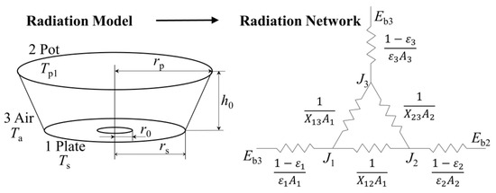
Figure 1.
Radiation heat exchange system.
On the right side of Figure 1, Ebi is the black body radiant ability of surface i (kW/m2; i = 1, 2, 3); J is the effective radiation of the surface (kW/m2); ε is the surface emissivity; and the X is the surface-to-surface view factor (i, j = 1, 2, 3).
The actual PCRB can be simplified as shown in Figure 1. According to Ohm’s law, the radiant heat transfer process of the combustion system can be equivalent to a circuit, so (1 − εi)/(εi·Ai) is the surface radiation thermal resistance of surface Ai, which reflects the radiant characteristics of the surface. Additionally, 1/Xij is the space radiant thermal resistance between the surface Ai and the surface Aj, related to the relative position of the two surfaces in space.
The node equation is listed, based on Kirchhoff’s law, as Equation (1). Therefore, the radiant heat transfer between any two surfaces in the sealed cavity Φi,j can be calculated according to Equation (2). Among them, X1,2 can be calculated by the radiation model of two coaxial parallel disks, similar to in Equation (3).
2.2.2. Calculation Model of Gas Radiation
Radiation of the flue gas Qg could be calculated according to Equation (4), based on the total emissivity of the mixed gas with a parallel infinity plate in the Leckner model [10].
The total emissivity of the mixed gas is εg; the bottom area of the pot is Ap1 (m2); the absorb rate of the mixed gas is αg; the average temperature between PCP and the pot bottom is Tg (K), and the total emissivity of pot is εp.
2.2.3. Calculation Model of Convective Heat Transfer
Convective heat transfer Qc could be calculated according to heat transfer on a flat plate and Newton’s law of cooling, as seen in Equation (5).
The convective heat energy and the convective heat exchange coefficient between the flue gas and the pot bottom and the pot side wall are Qc1, Qc2 (kW), hcon1, hcon2 (kW·m−2·K−1), respectively. The temperature of gas passing the pot bottom, gas passing the pot side wall, the pot bottom, and the pot side wall is Tf1, Tf2, Tp1, Tp2 (K), respectively. The area of the pot bottom and the pot side wall is Ap1, Ap2 (m2), respectively.
The calculation of hcon is based on fluid properties, such as conductivity λ, heat capacity cp, viscosity μ, density ρ, characteristic length L, and fluid velocity v. The qualitative temperature is the average temperature of the pot wall and the corresponding flue gas. The characteristic length L is the pot bottom radius rp and the pot height hp. The fluid velocity v can be estimated according to the corresponding mass and energy conservation equations.
2.3. Experiment
As shown in Figure 2, the primary device of the experimental system is a radiating burner (ejector, pre-mix chamber, PCP) with a 3.1 kW rated heat load. The ejector is a double-ring design, and the diameters of the internal nozzle and external nozzle are 0.72 mm and 1.25 mm, respectively. A PCP is used to burn, and several pot sizes are used to measure the radiation efficiency. The external diameter of PCP is 150 mm, and the internal value is 30 mm, with a thickness of 12 mm. The average size of a single fire hole is 1.15 mm × 1.15 mm, and the average spacing of the fire hole is 0.55 mm with an open porosity of 46%.
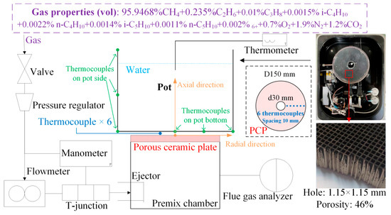
Figure 2.
Experimental system.
The gas properties are listed in Figure 2, so the low heat value Hl of the used gas is calculated as 3.28 × 10⁴ kJ/m3, and the density of gas ρg is 0.712 kg/m3 with a relative density s = 0.55. Therefore, the theoretical air L0 required to burn is calculated as 9.149 m3 per m3 fuel gas.
The burner uses low-pressure, fully pre-mixed combustion, so all the required air is ejected by the ejector, and the excess air coefficient equals the primary air coefficient. After calculation, when the primary air coefficient is 1, the theoretical flue gas volume is 10.140 m3.
Two kinds of pots, the BAP and the WBP, were used. The BAP is the standard test pot [17,18], and the WBP is a typical one whose surface is polished. The diameters of the pots are 240 mm, 260 mm, 280 mm, and 300 mm, and the heights of the pots are 150 mm, 160 mm, 175 mm, and 190 mm, respectively.
The information about the operating conditions is shown in Table 1.

Table 1.
Operating conditions.
2.4. Measurement
2.4.1. Temperature Distribution
Six OMEGA TJ72-CAXL-18U-12-CC thermocouples (A–F) can measure the highest 1149 °C distribution along the radius of the PCP from center to edge, and the spacing between each of them is 10 mm. Thermocouple A is located 20 mm away from the plate center, 5 mm away from the edge of the internal ring. Thermocouple F is located 70 mm away from the plate center, 5 mm away from the edge of the PCP. The thermocouples connect with the USB data acquisition module (OM-DAQ-USB-2400) to the computer that records the real-time measured temperature. The accuracy of the thermocouples is less than 5 °C when the range is higher than 1000 °C. The mean value in half a minute is used as the measured temperature during the steady combustion stage.
2.4.2. Heat Load and Thermal Efficiency
The heat load is related to the gas flow rate. The gas pressure is from 1.5 kPa to 3 kPa, stabilized by the pressure regulator, and the interval is 0.25 kPa. The gas flow rate is measured twice in 1 min. When the value difference is less than 2%, the average value is the measured value.
The temperature change of water represents thermal efficiency. The ambient temperature is 6~10 °C, the initial measured water temperature is 20 °C, and the temperature change is 30 °C. When the water temperature is 15 °C and 45 °C, the stirring begins; when the water temperature is 20 °C and 50 °C, the stirring stops. Two continuous experiments were conducted under the same conditions. When the thermal efficiency difference is less than 5%, the average value is the measured value. If not, it is repeated.
3. Results and Analysis
3.1. Temperature of Flue Gas
Figure 3a,b show a high-temperature zone of flue gas within 5 mm above the PCP. As the axial height increases, the flue gas temperature gradually decreases, forming a low-temperature area under the center of the pot bottom. In contrast, the overall level of the flue gas temperature under WAP is higher, and the distribution is more uniform than under BAP. On the one hand, the surface temperature of PCP under WAP is higher. From Wien’s law, the infrared wavelength emitted from PCP moves to the shortwave, while the water vapor and carbon dioxide have a strong absorption ability under the shortwave. On the other hand, the pot bottom will reflect more radiant energy due to the higher surface emissivity of BAP. Therefore, the higher heat transfer rate causes a lower flue gas temperature (964.54 °C to 622.95 °C) for the BAP compared to the WAP (1007.69 °C to 691.11 °C).
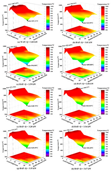
Figure 3.
Temperature distribution of the flue gas layer.
Take BAP as an example; the temperature of the flue gas is positively related to heat load, as shown in Figure 3c–h. Additionally, under different heat loads, the phenomenon that a low-temperature zone will be formed under the center of the pot bottom could be observed because high-temperature gas reaches a certain height by the heat press and flows along the radial direction. Due to the flowing characteristics of high-temperature flue gas, the flue gas layer is thin under the center of the pot bottom, and a thin wall jet region forms. Moreover, with the increase in heat load, the mass and the flowing velocity of flue gas increase, so the area of the low-temperature zone will reduce, and the temperature distribution will be uniform.
3.2. Surface Temperature of PCP
Figure 4a,b show that the center of the PCP is at a high temperature and the edge is at a low temperature, which is not influenced by whether there is a heated pot, and it is determined by the ejector structure and the outside heat dissipation. All thermo-couples show that the WAP temperature is approximately 60 °C higher than the BAP, which is also influenced by a lower heat transfer rate for the WAP. Furthermore, the WAP temperature is also higher than that without the pot, because the target environment is the surrounding environment, which is approximately 6~10 °C. The temperature difference between the WAP and the BAP is obviously, up to 66 °C. However, the temperature difference between the BAP and that without the pot is only 15–25 °C. The different surface emissivity of the target environment causes this, and it also influences the temperature of the flue gas at the fire hole outlet.
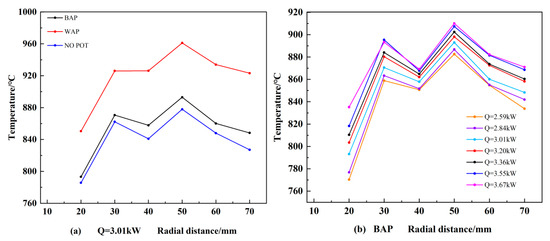
Figure 4.
Surface temperature of PCP. (a) The surface temperature of PCP under different operating conditions under heat load is 3.01 kW. (b) The surface temperature of PCP with BAP under different heat loads.
From Figure 3 and Figure 4, under the same heat load, the difference between the flue gas temperature and the PCP average temperature with BAP is higher than that with WAP. When the heat load increases from 2.59 kW to 3.67 kW, the temperature difference with BAP is above 90 °C. However, under WAP, the temperature difference is only approximately 50 °C.
Since the WAP has lower surface emissivity, most heat will be transferred to the PCP as the reflected radiation. In contrast, the BAP has a higher surface emissivity, so net radiant heat transfer is higher, which causes the temperature of PCP to reduce. Therefore, more heat will be transferred to PCP from the flue gas to keep the flame surface steady at the fire hole, and the temperature of the flue gas will decrease at the same time.
Additionally, the temperature distribution under different heat loads is similar to that under the rated heat load. With the increase in heat load, the temperature of all thermo-couples increases by a different degree, and the difference between the maximum temperature and the minimum temperature of PCP decreases, which means the temperature uniformity of PCP increases.
3.3. Thermal Efficiency
Figure 5a shows that the mean square error of the measured error is between 0.124% and 0.578%, which proves that the experimental results are well measured. Figure 5b shows that under the same heat load, the measured thermal efficiency (ratio of obtained heat of the water to the consumed fuel heat value) of the BAP is 15~20% higher than that of the WAP because of the different emissivity of different pot materials. With the increase in the heat load, the thermal efficiency of the burner increases first, and then decreases, but the peak is different for different kinds of pots. The maximum thermal efficiency of a burner under BAP is 68.78% when the heat load is 3.01 kW, but that under WAP is only 51.73% when the heat load is 3.36 kW.
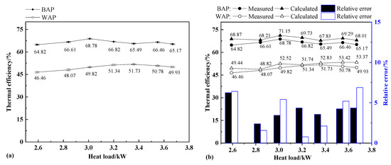
Figure 5.
Thermal efficiency analysis. (a) Measured thermal efficiency with error bar (mean square error). (b) Comparison of theoretical calculated thermal efficiency and measured value.
With the analysis of the theoretical model, the trend of thermal efficiency changes this way because PCRB’s convective heat transfer and the gas radiant heat transfer account for more as the heat load increases, but the solid radiant heat transfer accounts for less [19]. The weights of these three parts are related to the heat load, which will be discussed in Section 3.4.2. For example, for the BAP, a change in the convective heat transfer and the gas radiant heat transfer, caused by an increase in heat load, is the main factor under low heat load. Hence, the thermal efficiency increases when the heat load changes from 2.59 kW to 3.01 kW. With a further increase in heat load, the proportion of radiation decreases, which mainly lowers the thermal efficiency, so total thermal efficiency decreases with the increase in heat load under high heat load.
The calculated thermal efficiency is generally higher than the measured value. The less than 7% relative error is acceptable considering the inevitable heat loss, such as water evaporation, and so on. The weights of the heat transfer type are analyzed quantitatively based on the calculated value.
3.4. Characteristics of Radiation and Convective Heat Transfer
3.4.1. Radiant Heat Proportion of PCP
In Figure 6, the plate radiant output rate is the proportion of radiant energy from the PCP in the total input of the heat load, and the pot radiant absorb rate is the proportion of energy absorbed by the pot bottom in the radiation energy reaching the pot bottom.
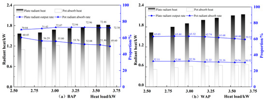
Figure 6.
Radiant heat of PCP under different heat loads.
The effect of the temperature improvement from the heat load decreases with the increase in the heat load under both the BAP and the WAP, so the plate radiant output rate decreases. This confirms the research results of [20]. The reason is that the PCP temperature does not change noticeably compared with the heat load, because the flame temperature is constant [21]. Consequently, the numerator of the proportion slightly increases, the denominator of the proportion also increases, and the proportion value decreases. However, the pot absorb rate fluctuates in a small range and does not change obviously, with the increased heat load.
A significant difference exists between the solid radiant absorb rate of the BAP (72%) and that of the WAP (31%). The space heat resistance 1/AsX12 is mainly determined by the structure between the PCP and the pot bottom, which does not change significantly with the heat load and the surface emissivity of the pot. Therefore, the main reason for the difference is the surface heat resistance of the pot (1 − εp)/εpAp1, which is highly related to the pot emissivity.
3.4.2. Heat Gain and Proportion of Pot
In Figure 7, when the heat load changes from 2.59 kW to 3.67 kW, the heat gain of the BAP through solid radiation, gas radiation, and heat convection increases by 21%, 67%, and 59%, respectively. However, under the same condition, the WAP increases by 27%, 69%, and 59%, respectively. Therefore, compared with the radiant heat from the PCP, the convective heat transfer and the radiation from the high-temperature flue gas increase much more.
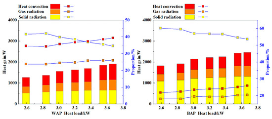
Figure 7.
Heat gain of BAP and WAP under different heat loads.
Additionally, the calculated value shows that the heat gain of the solid radiation of the BAP is twice that of the WAP. In contrast, the temperature of the flue gas under the WAP is higher, and the heat gain of convection is 10% higher than that of the BAP.
The radiant heat transfer of the PCP dominates the heat gain of the BAP. With the increase in the heat load, the proportion of the solid radiation decreases, but the heat gain from the convection and gas radiation of the flue gas increases. For example, when the heat load changes from 2.59 kW to 3.67 kW, the proportion of the radiant heat transfer of the PCP reduces from 60.13% to 53.63%, but the convective heat transfer rises from 21.80% to 25.94%, with the radiant heat transfer of flue gas from 18.07% to 20.43%.
However, due to the lower emissivity of the WAP, when the heat load increases to 3.3 kW or so, the primary heat gain of the pot changes to convective heat transfer from the flue gas. Although the temperature of the flue gas and that of the PCP could rise, to some extent, due to the radiation reflection of the WAP, this indirect way of heat recycling could not be utilized in this part of energy completely, so heat loss exists. The total heat gain of the WAP is noticeably lower than that of the WAP because of this.
3.5. Pot Emissivity
Figure 8 uses the theoretical model to estimate the changing trend of the heat transfer under the conditions where the pot emissivity increases from 0.62 to 0.82 with a heat load of 3.01 kW and a surface emissivity of the PCP of 0.90. In Figure 8, εp = 0.72 is chosen as the standard value. If the pot emissivity increases by 0.1, there is an additional 22.91 W (0.33%) of solid radiant heat gain, which means a 0.96% thermal efficiency improvement. However, if the pot emissivity decreases by 0.1, there is a 47.98 W (0.85%) solid radiant heat loss, which causes a 1.85% thermal efficiency drop. It should be noted that the slight change in the flue gas temperature is not considered, so actual thermal efficiency should be lower than the calculated value.
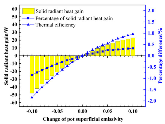
Figure 8.
Effective radiant heat gain changing with pot emissivity variation.
4. Conclusions
The heat transfer characteristics of PCRB and the target environment were studied by experimental and theoretical analysis. Firstly, comparative experiments were carried out using BAP and WAP with a surface emissivity of 0.72 and 0.22, respectively, to study the temperature distribution and thermal efficiency of PCRB. Then, the thermal efficiency calculation models of PCRB and pot were established based on the theory of radiation and convective heat transfer. The models also apply to other infrared radiation burners. Combined with the experimental data, the heat gain type of the burner is quantitatively analyzed. Finally, the influence of pot emissivity on the heat transfer trend of the burner and the pot is discussed. The conclusions are helpful in developing the coating of the pot, and the particular pot bottom for an infrared radiation burner. The main conclusions drawn are as follows.
The thermal efficiency of PCRB is influenced by the burner structure and the pot material, and the relationship is non-linear. The maximum thermal efficiency of BAP is 68.78% under a heat load of 3.01 kW, and that of WAP is 51.73% under a heat load of 3.36 kW. Under the same heat load, the measured thermal efficiency of BAP is 15~20% higher than that of WAP.
The pot surface emissivity decreases, and the heat gain of radiation also decreases, but the PCP and flue gas temperatures increase. Under the same heat load, when pot surface emissivity changes from 0.72 to 0.22, the temperature of PCP increases 70~90 °C, and the temperature of the flue gas at the fire hole outlet increases 15~25 °C, but the thermal efficiency decreases 15~20%. Therefore, only the improved temperature of PCP and flue gas may cause the effective heat gain to be lower because of the complexity of heat transfer, which is not beneficial to the thermal efficiency.
The heat transfer between PCRB and the target environment is mainly radiation. As the heat load increases, the proportion of radiant heat transfer decreases, and the convective heat transfer and radiation of the flue gas increases. Under different heat loads, the proportion of radiant heat gain of BAP is 74.06~78.20%, with convective heat transfer accounting for 21.80~25.94%. However, the proportion of radiant heat gain of WAP is 60.64~65.41% with convective heat transfer accounting for 34.59~39.36%. The relative error is within 7%.
When the heat load is 3.01 kW, and the emissivity of PCP is 0.9, the thermal efficiency increases from 69.31% to 72.11% as the pot emissivity increases from 0.62 to 0.82. Therefore, for any burner that mainly depends on radiation, higher thermal efficiency could be obtained using a higher surface emissivity of the pot or coat.
Author Contributions
Conceptualization, S.Z., Q.X. and S.P.; methodology, Q.X. and S.S.; software, Q.X.; formal analysis, S.Z., Q.X, and S.S.; data curation, S.Z., Q.X., and S.S.; writing—original draft preparation, S.Z., Q.X., S.S. and S.P.; writing—review and editing, S.Z., Q.X.; visualization, S.Z., Q.X. and S.S.; supervision, S.P.; project administration, S.Z. and S.P.; funding acquisition, S.Z. All authors have read and agreed to the published version of the manuscript.
Funding
The APC was funded by The University of Manchester.
Institutional Review Board Statement
Not applicable.
Informed Consent Statement
Not applicable.
Data Availability Statement
The data can be obtained from the corresponding author by reasonable requirement.
Conflicts of Interest
The authors declare no conflict of interest.
Nomenclature
| A | Surface area |
| cp | Heat capacity |
| Hl | Heat value |
| h0 | Pot holder height |
| hcon | Convective heat exchange coefficient |
| L | Characteristic length |
| L0 | Theoretical air volume |
| Q | Heat load |
| Qc | Convection heat transfer between flue gas and pot body |
| Qe | Effective heat gain |
| Qg | Radiant heat transfer between flue gas and pot bottom |
| Qs | Radiant heat transfer between plate and pot bottom |
| r0 | Ignition ring radius |
| rs | PCP radius |
| rp | Pot bottom radius |
| T | Temperature |
| X | Surface-to-surface view factor |
| Λ | Conductivity |
| μ | Viscosity |
| ρ | Density |
| ε | Emissivity |
| v | Fluid velocity |
| αg | Absorb rate of mixed gas |
| ηe | Total thermal efficiency |
| Φi,j | Radiant heat transfer between any two surfaces |
| φa | Input heat load |
Abbreviations
| BAP | Black Aluminum Pot |
| WAP | White Aluminum Pot |
| PCRB | Porous Ceramics Radiant Burner |
| PCP | Porous Ceramic Plate |
| WSGG | Weighted Sum of Gray Gas |
References
- Kamal, M.M.; Mohamad, A.A. Combustion in Porous Media. Proc. Inst. Mech. Eng. Part A J. Power Energy 2006, 220, 487–508. [Google Scholar] [CrossRef]
- Tidball, R.K.; Donaldson, R.J.; Gorrerba, J.A. Radiant-Burner Technology Base—Burner Research and Development. Final Report, February 1986–January 1989; Alzeta Corp.: Santa Clara, CA, USA, 1989. [Google Scholar]
- Fursenko, R.; Maznoy, A.; Odintsov, E.; Kirdyashkin, A.; Minaev, S.; Sudarshan, K. Temperature and Radiative Characteristics of Cylindrical Porous Ni–Al Burners. Int. J. Heat Mass Transf. 2016, 98, 277–284. [Google Scholar] [CrossRef]
- Maznoy, A.; Kirdyashkin, A.; Minaev, S.; Markov, A.; Pichugin, N.; Yakovlev, E. A Study on the Effects of Porous Structure on the Environmental and Radiative Characteristics of Cylindrical Ni-Al Burners. Energy 2018, 160, 399–409. [Google Scholar] [CrossRef]
- Keramiotis, C.; Stelzner, B.; Trimis, D.; Founti, M. Porous Burners for Low Emission Combustion: An Experimental Investigation. Energy 2012, 45, 213–219. [Google Scholar] [CrossRef]
- Keramiotis, C.; Founti, M.A. An Experimental Investigation of Stability and Operation of a Biogas Fueled Porous Burner. Fuel 2013, 103, 278–284. [Google Scholar] [CrossRef]
- Arrieta, C.E.; García, A.M.; Amell, A.A. Experimental Study of the Combustion of Natural Gas and High-Hydrogen Content Syngases in a Radiant Porous Media Burner. Int. J. Hydrogen Energy 2017, 42, 12669–12680. [Google Scholar] [CrossRef]
- Keramiotis, C.; Katoufa, M.; Vourliotakis, G.; Hatziapostolou, A.; Founti, M.A. Experimental Investigation of a Radiant Porous Burner Performance with Simulated Natural Gas, Biogas and Synthesis Gas Fuel Blends. Fuel 2015, 158, 835–842. [Google Scholar] [CrossRef]
- Eckert, E.R.G. Radiative Transfer, HC Hottel and AF Sarofim, McGraw-Hill Book Company, New York, 1967. 52 Pages. AIChE J. 1969, 15, 794–796. [Google Scholar] [CrossRef]
- Leckner, B. Spectral and Total Emissivity of Water Vapor and Carbon Dioxide. Combust. Flame 1972, 19, 33–48. [Google Scholar] [CrossRef]
- Vahidhosseini, S.M.; Esfahani, J.A.; Kim, K.C. Experimental Study on the Radiative Heat Transfer in a Multi-Hole Porous Radiant Burner with Internal Combustion Regime. Appl. Therm. Eng. 2022, 201, 117732. [Google Scholar] [CrossRef]
- Bubnovich, V.; Hernandez, H.; Toledo, M.; Flores, C. Experimental Investigation of Flame Stability in the Premixed Propane-Air Combustion in Two-Section Porous Media Burner. Fuel 2021, 291, 120117. [Google Scholar] [CrossRef]
- Yakovlev, I.; Maznoy, A.; Zambalov, S. Pore-Scale Study of Complex Flame Stabilization Phenomena in Thin-Layered Radial Porous Burner. Combust. Flame 2021, 231, 111468. [Google Scholar] [CrossRef]
- Vahidhosseini, S.M.; Esfahani, J.A.; Kim, K.C. Assessment of a Cylindrical Porous Radiant Burner with Internal Combustion Regime for Sustainable Energy: Numerical Analysis of the Radiant Efficiency and NO Production. Sustain. Energy Technol. Assess. 2021, 43, 100974. [Google Scholar] [CrossRef]
- Incropera, F.P.; DeWitt, D.P.; Bergman, T.L.; Lavine, A.S. Fundamentals of Heat and Mass Transfer, 8th ed.; WILEY: Los Angeles, CA, USA, 2017; ISBN 978-1-119-35388-1. [Google Scholar]
- Advanced Energy Industries Inc. Table of Emissivity of Various Surfaces. Available online: https://www.lumasenseinc.com (accessed on 1 March 2022).
- GB 16410-2007/XG1-2012; Domestic Gas Cooking Appliances (Including Amendment 1). China Standard Press: Beijing, China, 2013.
- GB 16410-2020; Domestic Gas Cooking Appliances. China Standard Press: Beijing, China, 2020.
- Fan, C.; Xia, X.L.; Du, W.; Sun, C.; Li, Y. Numerical Investigations of the Coupled Conductive-Radiative Heat Transfer in Alumina Ceramics. Int. Commun. Heat Mass Transf. 2022, 135, 106097. [Google Scholar] [CrossRef]
- Hashemi, S.A.; Nikfar, M.; Motaghedifard, R. Experimental Study of Operating Range and Radiation Efficiency of a Metal Porous Burner. Therm. Sci. 2015, 19, 11–20. [Google Scholar] [CrossRef]
- Vahidhosseini, S.M.; Esfahani, J.A.; Kim, K.C. Cylindrical Porous Radiant Burner with Internal Combustion Regime: Energy Saving Analysis Using Response Surface Method. Energy 2020, 207, 118231. [Google Scholar] [CrossRef]
Publisher’s Note: MDPI stays neutral with regard to jurisdictional claims in published maps and institutional affiliations. |
© 2022 by the authors. Licensee MDPI, Basel, Switzerland. This article is an open access article distributed under the terms and conditions of the Creative Commons Attribution (CC BY) license (https://creativecommons.org/licenses/by/4.0/).