1. Introduction
The energy transition implies a new model of social organization based on the production and consumption of energy from Renewable Energy Sources (RESs). The RESs are playing and will play an increasingly important role. It is essential to take into account their characteristics: non-programmability, uncertainty in the predictability of generation capacity, the lack of temporal coincidence between production and the final uses of energy demand and limited possibility of supplying regulation services.
Storage systems will play a central role for conventional uses (energy time shift; continuity service) and the network integration of RESs (synthetic inertia, Fast reserve, secondary and tertiary reserve, network congestion resolution, voltage regulation), system, network (transmission, distribution, local) and operator (producer/consumer) needs. The functional characteristics of storage systems can be divided into energy and power applications: the first one with a large capacity to exchange power for long periods (hours), the second one to exchange high power for short periods (seconds, minutes).
1.1. Motivation and Incitement
In this framework, different business models to better manage such sources (generation and storage) have been introduced. Among such models, the energy community or, in general, the end-user’s aggregation represents a solution to optimally manage the energy production of renewable energy sources, maximizing their use.
The European Commission, in 2016, to place the consumer at the heart of the energy transition, introduced the energy communities as part of the Clean Energy for all European Package (CEP). With the recent renewable energy directive (RED II) and the recent electricity market directive (EMD), a legal framework for “citizen energy communities” (CEC) and “renewable energy communities” (REC) was introduced to be interpreted and adopted into the member states’ national legislation. Although energy communities constitute now a legally defined and recognized entity by the institutions of the European Union, the directives that have been promoted and voted on at an energy community level do not appear to have been transposed yet into national law in most of the member states. Even in cases where there is a sufficiently defined national legal framework, there are low rates of energy communities’ development.
1.2. Literature Review and Related Works
Energy communities can be seen as an opportunity for citizens to actively participate not only in the community but also in the energy market [
1].
In [
2], the Local Renewable Energy Organizations are defined as organizations initiated and managed by actors from civil society, with the aim to educate or facilitate people on efficient energy use, enable the collective procurement of renewable energy or technologies or provide energy from renewable resources.
This definition, which anticipates the energy community one, highlights how the role of the citizen is central and how it is essential.
Indeed, the REDII gives a first definition of what RECs could be. Starting from the definition of renewables self-consumers and jointly acting renewables self-consumers [
3], the energy Community is defined. A renewables self-consumer is defined as a final customer who generates renewable electricity for their own consumption and who may store or sell self-generated renewable electricity activity. According to the RED II, an REC can be considered as a legal entity based on open and voluntary participation, and autonomous, controlled by its shareholders or members. Such shareholders or members are in the proximity of renewable energy projects owned and developed by that legal entity. Its primary purpose is to provide environmental, economic, and social community benefits rather than financial profits.
Moreover, the CECs are defined. The differences from RECs are that they may engage in generation, including from renewable sources, distribution, supply, consumption, aggregation, energy storage, energy efficiency services or charging services for electric vehicles or provide other energy services. Another main difference seems to be the proximity aspect that characterizes the RECs [
3] instead of the participation of CECs that can be spread over the territory.
The RECs aim for the participation of individuals to improve the local acceptance of renewable energy, local investment and improved participation of citizens in the energy transition [
3]. The RECs will produce, consume, store and sell renewable energy, share produced renewable energy within the community and access energy markets in an integral way [
3].
One of the open questions related to the RECs is the optimal number, the power plant size and the optimal mix of the several kinds of end-users to obtain the best environmental and economic results.
In [
4], the main advantages of energy communities are underlined:
- -
cost reduction in the energy vector procurement;
- -
improvement of reliability and quality supply;
- -
active participation of citizens and use of local resources.
If an energy community, both REC and CEC, must be implemented, to obtain the aforementioned benefits, enabling technologies have to be considered. Such technologies, in some features, can be compared to the Demand Response (DR) enabling technologies.
In [
5], an analysis of the enabling technologies for the DR has been carried out and has been divided into technologies for the Utility Domain and those for the End-User Domain. They are divided into four categories: metering and monitoring devices, control devices, communication systems and software programs. The same consideration about the enabling technologies can also be taken into account for the technologies used for the implementation and management of energy communities, even considering that DR (implicit or explicit) is one of the management methods of the energy communities. The technologies for both utility and end-user domains should provide a platform for the control and management of users’ data with the aim to keep them informed on their behavior. There is the necessity of measuring and monitoring infrastructure for the several present devices of a control infrastructure, a communication system and of several software programs for managing the various data according to algorithms and the control of the field devices.
In [
6], the different technologies that currently play a significant role in the transition to a Smart community were analyzed, not only considering energy aspects. Some of them are also important and are used as enabling technologies for energy communities. Among such technologies, there are the IoT devices, the cloud computing, the platforms and the sensors. From such devices, there is a huge quantity of data that must be analyzed as well as stored, so issues related to big data interest also affect the Energy Community implementation.
In [
7], it is shown how the aspects related to enabling technologies, even in different fields, concern various sectors, ranging from sensors to security protocols, to problems relating to big data, to the information communication and technology systems.
Starting from this, both for smart cities but also in other areas such as energy communities, they lead to various challenges and solutions concerning the technical, environmental and socio-economic aspects.
In [
8], a review of enabling technologies to develop a smart building is reported. Additionally, in this case, the different involved fields are analyzed, and the issues are underlined. Considering the particularity of IoT technologies, the necessity of network, cloud, system analytics, actuators and user interface is underlined.
In [
9,
10], a platform for energy communities is implemented, and the structure is presented. It is useful to collect and analyze the data inside the Energy Communities with the purpose to encourage the users to have aware behavior. This platform has to integrate a huge quantity of data deriving from the enabling technologies such as smart meters.
An aim of the platform is to manage the users of energy communities, providing them with useful services, as implemented in [
11]. Among the services that can be provided using an opportune platform, there are those associated with blockchain that allow users to trade energy in a community [
12]; when local energy trading and in particular renewable energy exchange are considered, the smart contract assumes a fundamental role, as described in [
13,
14,
15]. This allows both to operate the day ahead and in a quasi-real-time way, providing services to the grid.
1.3. Contribution and Paper Organization
The enabling technologies presented in this paper are:
- -
the smart meter, to measure and monitor the production and the load consumption for the end-user’s engagement, awareness and empowerment [
16];
- -
the DC Nanogrid (DCNG), for real-time management of power flows among several types of generation and storage units and to maximize the shared energy in an Energy community framework [
17];
- -
a platform for Energy Community management and so to support their creation, constitution and development.
The contribution of the paper is:
A review of the principal enabling technologies;
A specific settlement of the “advanced end-user”, illustrating its technological configuration and identifying the necessary enabling technologies (smart meter, smart energy storage system, DCNG and the Energy Community Management platform (ECM));
The DCNG as the main enabling technology for the cooperation of more advanced end-users in the context of energy communities to maximize the shared energy;
The definition of some use cases and corresponding performance indexes to evaluate how a single advanced end user can operate and when it operates in an REC with the DCNG as the grid interface;
Demonstration test cases.
One of the issues of the related works is that the enabling technologies are described for a particular scope of an energy community or in general for an aggregation. There is no literature on such technologies relating to Renewable Energy Communities. Moreover, such technologies are not utilized in the context for which they are described. In the present paper, such technologies are described from a system point of view, then an example of such technologies is implemented and utilized, showing the performance both of such technologies and of their operation in an energy community.
2. Principal Enabling Technologies for the Rec Implementation
To meet the objectives of decarbonization and to allow the energy transition to be effective, cultural changes based on energy saving and consumption efficiency must be started.
A change in producing, storing, consuming and exchanging energy is needed to be self-sufficient; at the same time, the energy is shared, and citizens are involved in the sustainable development of their city.
Therefore, a series of enabling technologies that allow all of this to be possible become necessary, allowing the integration of different resources that would otherwise be difficult to integrate. At the same time, they allow and facilitate the implementation and management of energy communities.
In the paper, the attention is focused on the smart meter (SM), energy storage system (ESS), DCNG and Energy Community management platform (ECM).
2.1. Smart Meter Description and Peculiarities
Among the various enabling technologies for the Energy community, there are technologies that allow us to measure and monitor the power exchanged by the end-user with the grid; this is allowed by the smart meter (SM).
It consists of an energy monitoring system, which allows us to analyze electricity consumption and production both for residential and industrial end-users. This can allow the end-user to optimize the use of RES generation and change their behavior to reduce energy consumption.
The SM, in addition to having the purpose of making the end-user aware of their behavior, is used to monitor and acquire the various data that will be used for the energy management and optimization platform for the REC.
The end-users are monitored, including consumers, producers and prosumers, and, according to these data, it is possible to proceed to manage energy to maximize the self-consumption to provide flexibility services to the grid, as well as to balance the energy within the aggregation.
In [
18], it is highlighted how, with the introduction of SMs, it is possible to offer new services: providing more detailed information on electricity, using ad hoc applications or simply informing how to save energy.
At the level of DSO, and in particular of the energy provider, the use of the SM is an essential tool to limit energy fraud, alongside that of the development of smart grids, including a variety of different components.
In [
19], an analysis of the SMs and their different uses is carried out.
In [
20], the role of SMs in monitoring the network and providing services for energy communities is analyzed, highlighting how time resolution is a parameter that must be taken necessarily into consideration according to the services and the purpose of such technologies.
In [
21], it is highlighted how the use of an efficient monitoring system, especially of reactive power, is also useful in compensating for the power factor in a system where reactive power represents a problem. It is also highlighted how the use of the saved data allows for the improvement in the compensation operations of this power factor. The utilization of such data allows in fact to carry out an accurate analysis of the users.
In [
22], it is highlighted that a high temporal resolution is necessary to be able to develop models for the management of domestic users. This is underlined also in this paper, where a particular SM with a high temporal resolution for management and monitoring purposes is utilized.
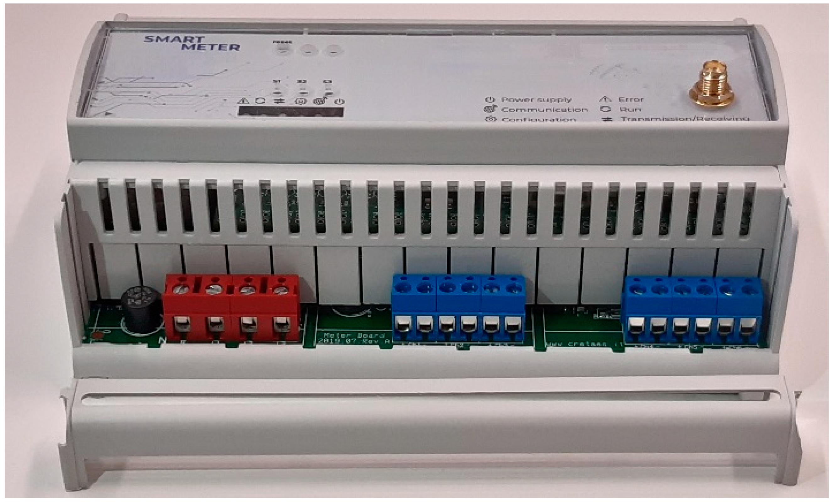
The SM has brought advanced functionalities oriented to smart grid and end-user needs such as the Demand Side Management (DSM) for unregulated market trading and real-time information. The proposed SM, as depicted in
Figure 1, is realized to change a normal citizen into an active smart citizen with its energy behavior.
Smart citizens changing their lifestyle routines and energy consumption can provide energy services and consumption flexibility, also reducing their energy costs. A smart citizen becomes part of a ‘smart energy community’ and helps to ensure the quality of supply and environment preservation.
The SM’s functionalities are understandable, user-friendly and standardized and provide a broad range of technical functionalities to inform end-users about their consumption, helping to increase awareness of energy consumption and, furthermore, engage them actively to participate in the electricity (and gas, water, heat) supply market.
Smart Meter Communication
To allow the acquisition of measurement data recorded by SMs, a software prototype has been developed on the cloud and stores the data on a MySQL relational Data Base (DB). The software communicates with the SMs from which it acquires electrical measurements.
The data stored on a DB are appropriately aggregated and analyzed to be used as input for any dashboard for the users or for the aggregator.
Such SMs obviously need a reliable internet connection to send the measured data every required time step (5 s in this case) and thus avoid their dispersion in order not to affect the operation of the same optimization and energy management models.
This Smart Meter is a combination of both hardware and software. The hardware part was designed and built on an electronic board that must condition electrical quantities to create an intelligent monitoring tool. The software management of the smart meter was implemented using a TM4C1294 Texas Instruments microcontroller.
All the electrical quantities to be monitored are suitably transduced and conditioned to be acquired by the ADCs of the microcontroller.
For simplicity, an HTTP-based communication has been adopted. APIs that the smart meter invokes have been developed.
The data stored on the DB are appropriately aggregated and analyzed to be used as input for any dashboard for users or for the aggregator.
The data are measured with a granularity of 5 s, which allows both to see details that otherwise would not have been visible and to perform a more precise power control, as explained in [
16].
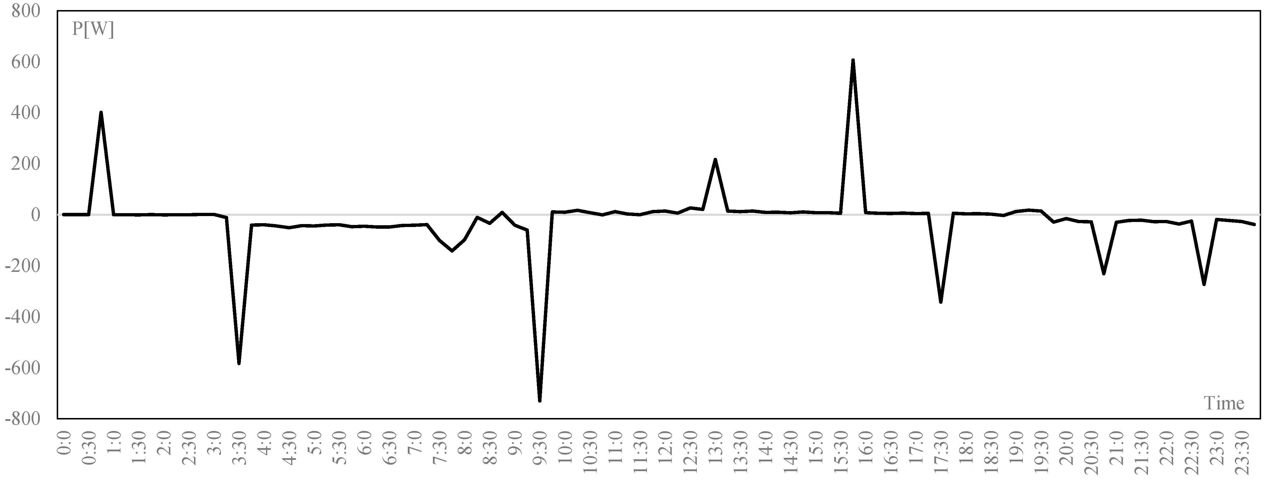
In
Figure 2 the difference between a profile with a time step of 5 s and 15 min is reported, where it is possible to see how the 5 s profile allows to provide more detailed control and management.
2.2. Energy Storage Systems
Electric storage systems include a broad category of devices. A classification of ESSs frequently adopted in the literature refers to the specific form of energy and distinguishes the storage systems in:
electrochemical storage (lead acid batteries, lithium-ion batteries, zebra, nickel-metal hydride etc.).
mechanical-type storage (CAES compressed air storage, high- and low-speed mechanical flywheels, pumping hydroelectric basins).
electrostatic storage (supercapacitors).
electromagnetic storage (superconductive magnetic energy storage—SMES).
chemical storage (hydrogen).
The storage systems are generally chosen based on the service they are required to perform, the power service and/or the energy service.
Energy storage systems can serve at various locations in which electricity is produced, transported, consumed and held in reserve (backup). Depending on the location, storage can be large-scale (GW), medium-sized (MW) or it can use micro and local systems (kW).
The most used technologies are the Li-ion batteries, super-capacitor and PEM-based power-to-hydrogen.
These ESSs can achieve very high performance in terms of response speed and the modulation of power. The impact will be as incisive as possible to implement an aggregate and coordinated management as Virtual Storage. In this perspective, the virtual ESSs represent an important resource for the national electricity system, with the aim of providing synthetic inertia services (very intense response lasting a few seconds) and fast reserve (delivery time up to fractions of an hour), i.e., regulation services to the frequency variation, as well as peak shaving and load leveling functions, i.e., functions for the reduction in power peaks and flattening of the load curve.
The need for some of these services, in particular, that of the fast reserve, has led European TSOs, including TERNA, to promote pilot projects. To date, the storage technologies present on the market, in particular, the electrochemical ESS, are interfaced with the network through converters and control and management systems that are not easy to integrate and coordinate with each other.
The new storage capacity, appropriately controlled and managed, would allow the supply of synthetic inertia services to the network to restore the system inertia of fast reserve to speed up the response of the primary regulation to restore the nominal frequency value in the network, peak shaving and/or the load-leveling services necessary to support the penetration of the RES into the electrical system.
Therefore, the installation of storage systems is a promising solution to support the integration of RESs, particularly when devices are intelligently coordinated, such as virtual storage plants (VSPs), to provide a wide range of energy services.
Energy storage can supply more flexibility and balance to the grid, providing a backup to intermittent renewable energy. Locally, it can improve the management of distribution networks, reducing costs and improving efficiency. More in general, energy storage can provide many valuable services across the whole energy system. Indeed, energy storage is essential to balance supply and demand. Peaks and troughs in demand can often be anticipated and satisfied by increasing or decreasing generation at short notice. In a low-carbon system, intermittent RESs mean it is more difficult to vary output, and rises in demand do not necessarily correspond to rises in RES generation. Higher levels of energy storage are required for grid flexibility and grid stability and to cope with the increasing use of intermittent wind and solar electricity [
23].
2.3. DC Nanogrid
To support this energy transition, it will be necessary to use system management, exploiting new flexible resources such as the previous mentioned smart storage systems to ensure adequate levels of system stability, safety and resilience, and so a new paradigm in terms of small-scale hybrid systems to integrate and coordinate decentralized distributed flexible resources is needed.
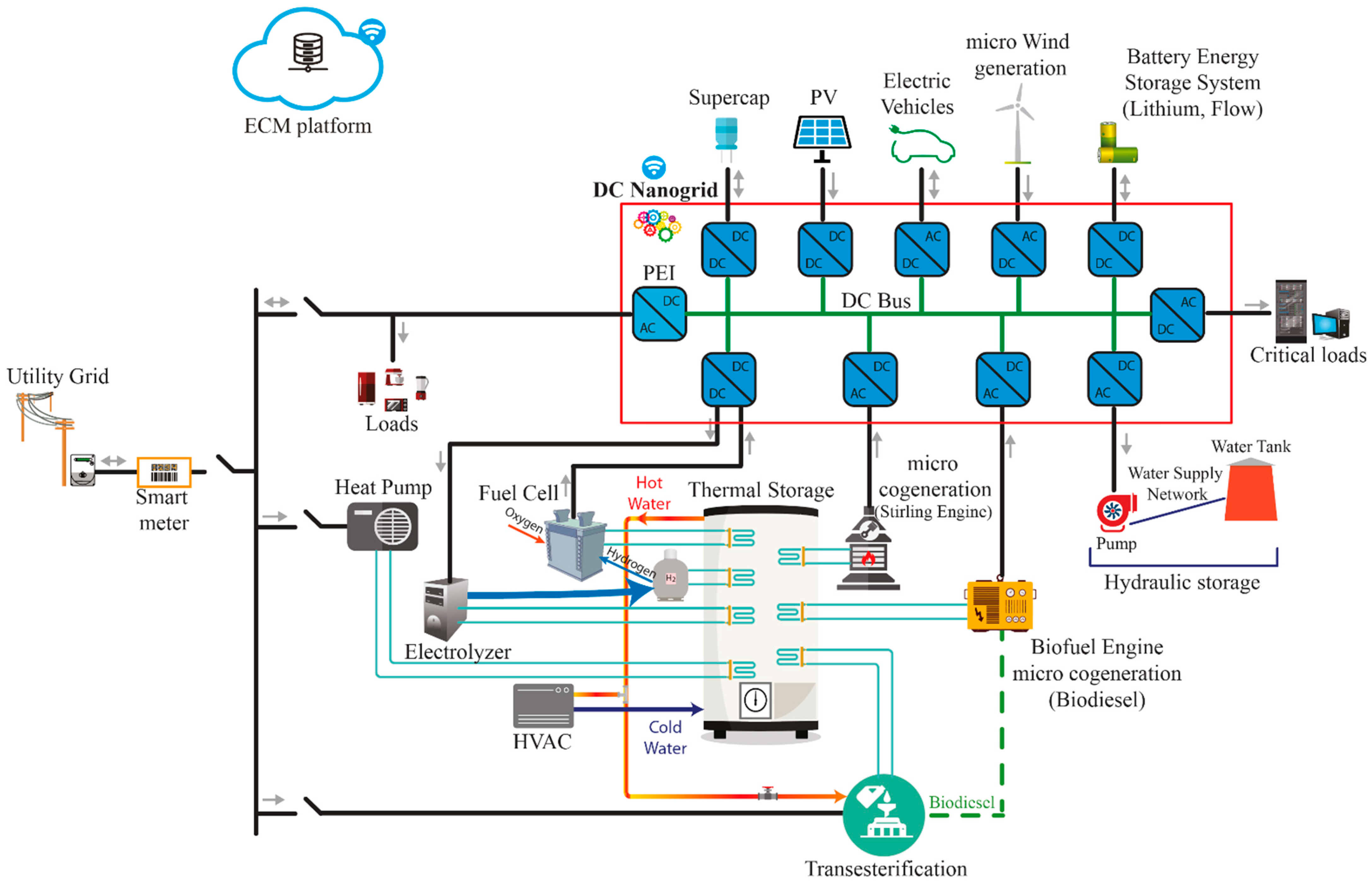
The DCNG is a hybrid system to maximize the self-consumption, accumulation and sharing of energy from renewable sources.
It can integrate different power sources and storage systems supplying uninterruptible and interruptible loads. It can operate when interconnected to the electricity grid but at the same time also in islanded mode (see
Figure 3).
It represents a change in the plant engineering paradigm, interposing a DCNG as an interface between the end-user loads and the grid, behind the meter.
It is a complex and modular hybrid system of conversion and energy control systems capable of simultaneously managing multiple types of generation sources and/or storage systems of different technologies, as well as exchanging power with the electricity grid.
Under regular operating conditions, the DCNG operates to satisfy the critical load’s demand, maximizing the use of RES generation when it is not required to follow a given power profile to be exchanged with the electricity grid (required by a central energy management system).
On the contrary, when it is required to exchange a given power with the electricity grid, the DCNG operates to exploit the integrated RESs and storage units, but at the same time guaranteeing continuity in supplying the critical loads.
The DCNG energy management is based on the DC Bus Signaling (DBS) strategy. The voltage of the DC bus on which the various RES and storage units are integrated is used as the only control signal. Indeed, there is no communication between the different sources, generation, storage system and loads. They operate independently with the voltage of the DC bus as a reference, through which the power flows are managed [
17].
This hardware and software configuration, therefore, allows the management of the DCNG in an automated manner, reducing the interaction with other components. This enables the automated participation of the end-users.
The DCNG has a modular architecture capable of being extended both “locally”, by connecting various devices to the base module (see
Figure 4), consisting of a PV plant and a conventional battery ESS, and in a widespread manner, by physically connecting multiple DCNGs via their DC bus or even by virtually interconnecting different DCNGs through an internet connection (
Figure 3), managed by the EMP based on the Power Cloud approach [
23].
In this way, an advanced end-user (AEU) is defined: an aware and active end-user, which is a consumer with an installed smart meter, a PV plant (prosumer) and a smart storage system (prosumager) coordinated by the DCNG, configured as illustrated in
Figure 5.
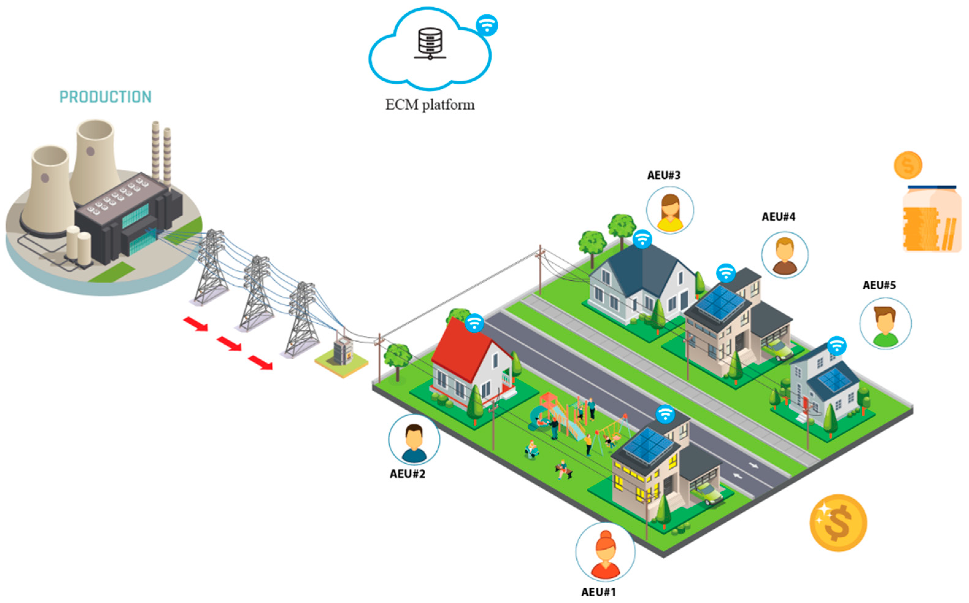
Several AEUs can cooperate among them so as to create an energy community (
Figure 6) in compliance with actual and future regulations and technical and market rules. Coordinating the various AEUs, it is possible to maximize the economic return of the members of the whole energy community, maximizing the self-consumption rate until it tends to assume the behavior of a “Nonsumer” and at the same time supports the network when required to provide flexibility services.
2.4. Energy Community Management Platform
To manage the various AEUs in a coordinated manner, it is necessary to implement an Energy Community Management (ECM) platform that allows the exchange of data and, therefore, allows monitoring, communication and control.
2.4.1. The Communication Architecture
The data flow scheme for communication between the ECM platform, the DCNG and the smart meters is illustrated in
Figure 7. In addition to the integration and management of PV generation and storage systems, the DCNG can communicate with the ECM platform. An aggregator, with the help of the energy management platform, manages the REC. The aggregator, in real time, monitors the power exchanged with the grid by end-users with SMs (User Data) and the status of the DGNG (NG Data). In addition, the aggregator can send to each DCNG a set of values, as set points, which translates into the power profile exchanged with the grid, which the DCNG must try to follow.
The communication by the aggregator takes place on a broadcast channel, so the AEUs, “members” of the REC, are enabled to receive the set points.
2.4.2. Platform Communication Protocol
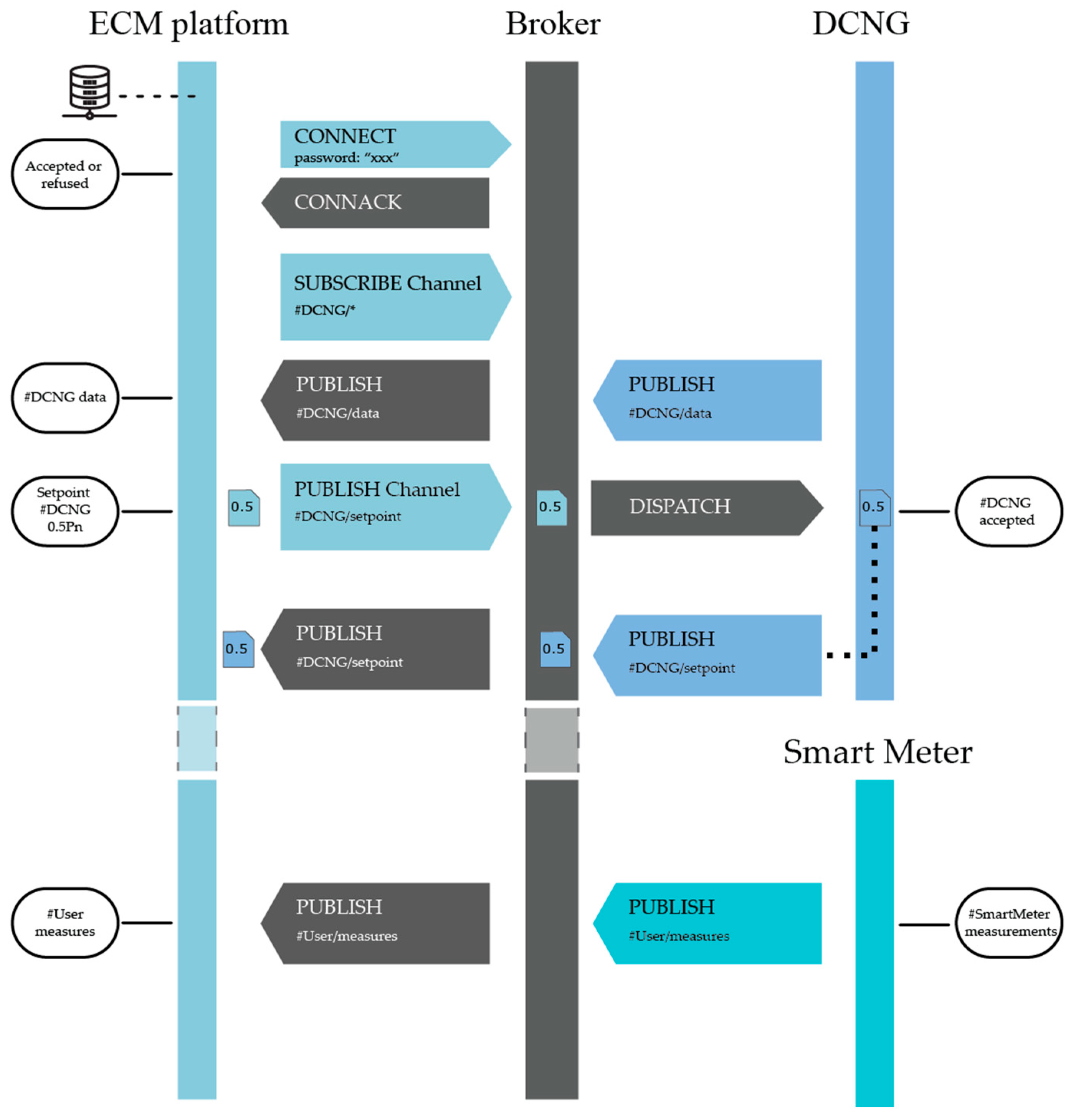
The data communication protocol between DCNGs and SMs with the ECM platform is a Machine-To-Machine communication, using Message Queue Telemetry Transport (MQTT), assuming that the channel is encrypted using SSL, for which an MQTTS protocol was used.
The SM is only able to issue messages, while the DCNG can issue messages and receive/issue commands. Two types of messages have been foreseen in the communication: active and reactive. A message is said to be active if it is transmitted by the DCNG without a request from the aggregator (for example, the transmission of a malfunction alarm), while a message is reactive (synchronous type) when it follows a request–response-type scheme, the aggregator requests specific information from the DCNG or when sending specific commands.
The communication architecture, in terms of the MQTT protocol, is represented in
Figure 8, where the Broker is represented by the energy management platform while the Server is the DCNG.
It should be emphasized that the exchange of information takes place on a broadcast application channel, which is 1:n. Each DCNG and SM enabled to communicate on the broadcast channel represents the members of the community.
The communication architecture used is the Publishers/Subscribers type and includes:
- -
a broker server that queues messages from various community members;
- -
a client able to subscribe and publish messages on a particular channel made available by the Broker;
- -
one or more “listeners” such as DCNGs which receive messages published on the Broker’s channels and perform certain functions.
The communication provides for a flow control for authentication based on a username and password registered in the DCNG and in the SM. Both DCNGs and SMs send messages with state-type operations containing information on the status of the DCNG (#NG/data) or the measurements taken by the SM installed by the user (#User/data). Finally, in the communication flow, there are also messages with action-type operations, where the aggregator sends the setpoint to be followed to the individual DCNGs.
The data are encapsulated in a string message encoded according to the JavaScript Object Notation (JSON) format, and its content is divided into a header and a body. In the header, in addition to useful information for flow control (Sequence number, Request ID), there is the “operation” key, which indicates the type of operation to which the body of the message refers. There are two types of operation, type “action” and type “state”. An action-type operation is used to send commands to the DCNGs (for example, the aggregator sends the set points to the DCNGs), while a state-type operation is used by the DCNGs themselves and by the SMs to send data (for example, measurements taken by the SMs and/or other information such as the state of charge of the ESS).
2.4.3. ECM Platform Description and Operation
The ECM platform allows the management of the data coming from the various AEUs (DCNGs and SM), the provision of services and the elaboration of any management algorithms implementing the ECM platform processes, as follows.
ECM Platform processes
Day-ahead self-consumption optimization: The process aims to optimize the power flows exchanged with the energy storage system to maximize self-consumption using deterministic equations that also consider production and load forecasts such as those relating to the storage system. This algorithm, using the SOC forecasts for the ESS, divides the energy surplus among the different ESSs and at the same time uses the stored energy to supply the loads. Power swaps are scheduled the day before.
Day-ahead dispatching services: Through this process, the scheduled availability of the day before is provided for individual AEUs (equipped with an energy storage system) to change their profile, therefore, to provide services to the network if required. Starting from the previous process, the SOC of the various ESS is evaluated and, if it is greater than a reference SOC, the availability to provide services to the network is scheduled/communicated. Using the availability of individual AEUs determines the availability for the entire REC.
The real-time management of requests to modify the exchange power profile: starting from what was programmed the day before, this process calculates in real time the power that the AEUs must exchange with the storage systems to provide the services requested if necessary [
8]. If the grid operator sends a new request in terms of the power profile to exchange with the grid, according to the communication of the day before, this must be provided by the REC. This request is distributed among the AEUs, as REC members, according to the previously determined availability.
Real-time balancing profile process: since the previous processes are based on forecasts, there could be errors in the forecasts. For this purpose, through this process, it is possible to balance the power between what is programmed and the real power profiles, opportunely charging and/or discharging the energy storage system [
8]. In particular, the comparison was drawn between the forecasts and the power measurements and, according to the real SOC ESS, the power is modified.
ECM Platform Services
Day-Ahead User Load Prediction: This service predicts the day-before hourly load for the different end-users in the aggregation.
Forecast of the day-ahead AEU production: This service allows the forecast of the hourly production of the day ahead for end-users to be equipped with a photovoltaic system.
Forecast of the day-ahead ESS state of charge: This service is used for the forecast of the SOC of the different ESS which is useful for providing the energy planning of the day ahead.
Day-ahead ESS charge/discharge profile: through this service, the energy that the ESS must exchange is scheduled the day ahead.
Forecast of the day-ahead AEU trading power profiles: it determines the power (injection and absorption) that the AEU will exchange with the network.
Day-ahead AEU dispatching service availability: this service is useful for calculating the availability of the individual AEUs to modify your profile and provide flexibility services to the grid.
Availability of day-ahead dispatching services: starting from the AEUs’ availability to provide services to the grid, the willingness to provide services of the REC is determined.
Real-time forecast of the ESS state of charge: it determines the power that the aggregation must exchange to provide services to the grid in real time.
Real-time state of charge of the user’s energy storage system: this service divides the power to provide services to the grid among the various end-users, previously determined for the REC.
Real-time AEU energy storage system charge/discharge: using the day-ahead schedule and real-time services, the power that the ESSs need to exchange is determined.
Real-time AEU exchange power profile: it determines the power that the end-user must exchange with the network, considering both the real-time and the previous day’s planning.
End-users real-time power balance services: the last service determines the power that the AEUs must exchange to limit the imbalance between the programmed day-ahead power profiles (injection and absorption) and the real-time ones.
2.4.4. Utilized Management Method
In [
17,
24], the authors present the model to optimally manage the power flow, providing services to the grid. The proposed control strategy is utilized not only to locally control the energy needs of a single AEU but also to manage more than one AEU, which constitutes a Renewable Energy Community. They also provide services to the grid, in particular, balancing services. To this scope, the power surplus has been injected into the grid or into the storage system, as requested by the operator.
The method can be used for more days and different time intervals. The objective function (
OF) allows several optimization aims for the exchanged power with the grid. The minimization of the overall exchanged energy, maximum power and power peak for a defined time interval can be requested:
where
is the exchanged power with the grid for a single user, for the time interval
t and for the day
d. This method is subject to several constraints that concern the exchanged power with the grid, the stored energy, the power exchanged with the storage systems and other conditions, as defined in [
17,
24].
3. REC Performance Indexes
The REC performances can be evaluated using some specific indexes. They have been defined considering both the H2020 research projects on this theme, the Italian national directives [
25,
26,
27], what has been proposed in the literature [
28] and based on the data stored in the ECM platform.
3.1. Indexes for the Single AEU and for the REC Performance: Self-Consumption and Self-Sufficiency Indexes
The aim is to identify indexes, in addition to the AEU’s local energy self-sufficiency, to have information regarding the quality of the self-consumption carried out inside the REC.
The indexes used to evaluate the degree of individual or shared/collective self-consumption can be measured with reference to different time intervals (hour, day, month, year), although the most useful is the hourly, as considered in this paper.
The collective self-consumption index must be “normalized”, comparing the amount of energy consumed in a time interval with the amount of renewable energy produced and available to evaluate the benefits related to the shared self-consumption in the energy communities.
The aim is to individuate and reward the AEUs most virtuous in terms of self-consumption and shared self-consumption, that is, concentrated in the hours of maximum RES production. It is necessary to build an index that returns information that is not only quantitative but also qualitative.
For this reason, in the calculation of shared self-consumption, it was decided to compare local consumption with the total consumption of the aggregation, normalizing the index.
The following variables will be used in the formulation of the proposed indexes:
- -
h: 1, 2, …, 24 index representing hours;
- -
i: 1, 2, …, n index representing the REC AEU number;
- -
g: 1, 2, …, Ng index representing the month day;
- -
: energy produced by the AEU i in the hour h;
- -
: energy produced from all RES generation plants inside the REC in the hour h;
- -
: energy absorbed by the AEU i in the hour h;
- -
: energy absorbed by all REC AEUs;
- -
: energy shared by the REC, according to the ARERA definition, provided in the regulation 318/2020/R/eel. It is defined as the minimum between the hourly value of energy produced by renewable sources and the sum of the energy adsorbed by all the loads of the community.
- -
: locally self-consumed energy or energy self-sufficiency, it is represented by the minimum value between the AEU’s production and consumption on the same site.
3.1.1. Hourly Shared Community Self-Consumption Index (IAC)
The index refers to the shared self-consumption of the REC in relation to the total amount of energy produced in the same hour (
) from all RES generation plants. It expresses the relationship between the energy shared in the hour and all the energy produced in the same hour. The index varies between 0 and 1 and is formulated as follows:
3.1.2. Individual AEU Hourly Local Self-Consumption Index (IAS)
It is the ratio between the hourly, locally self-consumed energy and the energy produced in the same hour by the same AEU (when production is greater than zero).
3.1.3. Single AEU Hourly Shared Self-Consumption Index (IAC)
The index refers to the self-consumption of the single AEU and corresponds to the percentage of the collective shared energy that is consumed by the AEU when it is produced (the energy stored in local storage for AEU is also counted as instantly self-consumed energy).
Considering the renewable self-produced energy given by the self-consumption index
and the locally consumed energy compared to the total energy (
/
), the index is normalized with the hourly production
compared to the maximum generation contribution of the user (
). The index varies between 0 and 1 and can be calculated as:
The first term is the load power of the AEU in the hour compared to the total REC load in the same hour. The second term represents the normalized self-consumption index, that is, the product between the collective self-consumption index and the normalized AEU’s production. It is possible to determine the shared self-consumption indexes, both individual and collective, on other time scales (daily, monthly or yearly) using the same formulas reported above appropriately scaled over the correct time horizon.
3.1.4. Services Request Reliability Index (ISRR)
The index refers to the ability of the AEU to satisfy a flexibility service request. It can be defined for each day, for the community or for the single AEU. It is the ratio between the error valuated as the difference between the averaged actual exchanged power (
) and the averaged request power
), and the averaged actual exchanged power (
).
4. Experimental Use Cases
The aim of the experimental use cases is to demonstrate the need for accurate, efficient and effective technologies for the implementation of RECs. In particular, it is shown how these technologies can interact with each other to achieve different results. For example, maximizing the self-consumption of the single AEU with or without the provision of flexibility services. These goals are achieved by exploiting local generation from RESs and ESSs.
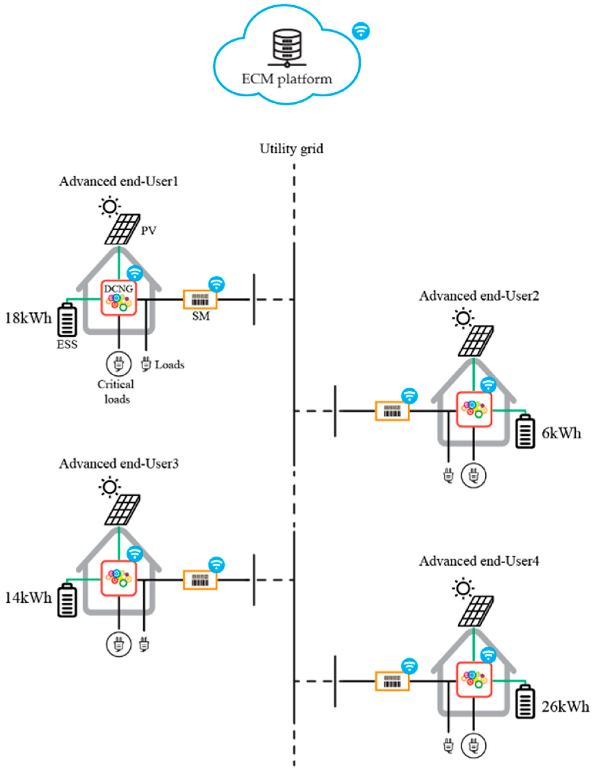
The implemented and analyzed use cases consider a REC of four AEUs, as illustrated in
Figure 9. Each AEU is equipped with a 3 kW PV plant, an ESS, a converter to supply the critical loads and a converter for the interface with the grid; other external loads are monitored through an SM. The difference consists of the capacities of the ESS, which, respectively, are: 18 kWh, 6 kWh, 14 kWh and 26 kWh.
The AEUs are interfaced through the ECM platform using the communication architecture before described.
Firstly, the analysis is carried out considering only one AEU operation and after the REC one. Three use cases are identified and analyzed, as illustrated in
Table 1 and below described.
(a) Use case 1(UC_1): AEU self-consumption without any flexibility service request.
This use case interests the single AEU. Its aim is to demonstrate that the AEU, through the DCNG with its control and management system of the RES generation and storage units, can maximize the use of local generation and the local self-consumption, therefore minimizing the CO2 production and the energy costs at the single AEU level.
For the performance evaluation of this use case, the IAS, hourly local self-consumption index, is used.
(b) Use case 2 (UC_2): AEU self-consumption with a flexibility service request.
This use case interests the single AEU. Its aim is to demonstrate that the AEU, through the DCNG with its control and management system of the different RES generation and storage units, can maximize the use of local generation and the local self-consumption and promptly satisfy a flexibility service request.
In this use case, the grid operator (TSO/DSO) or an intermediary operator (such as Balancing Service Provider—BSP) sends the flexibility request to the AEU, which operates through the DCNG to follow such a request. The DCNG operates by controlling its internal flexibility resources to follow the required power profile, minimizing the difference between the requested profile and the real-time power profile.
In this use case, the IAS and ISRR indexes are evaluated.
(c) Use case 3 (UC_3): REC self-consumption without and with a flexibility service request.
In this use case, we observe the real-time operation of the AEUs operating as an REC.
In this case, we first observe how each AEU behaves when a flexibility service is not requested and, therefore, when they operate in the community simply to increase the self-consumption of the same.
Subsequently, a request for a flexibility service is assumed, and then the behavior of each AEU is analyzed.
In this use case, the hourly IAC and ISRR indexes are evaluated.
5. Numerical Results
The numerical results have been obtained using the AEU laboratory prototypes implemented in a LASEER laboratory (see
Figure 10). Each AEU is configured as illustrated in
Section 4 and uses the DCNG with its own control and management system for the RES generation and storage units.
5.1. Test–UC_1
In its operation, without any external flexibility request, thanks to the DBS strategy, the DCNG maximizes the use of local generation and at the same time minimizes the CO
2 emissions, reducing the energy exchanged with the grid [
17].
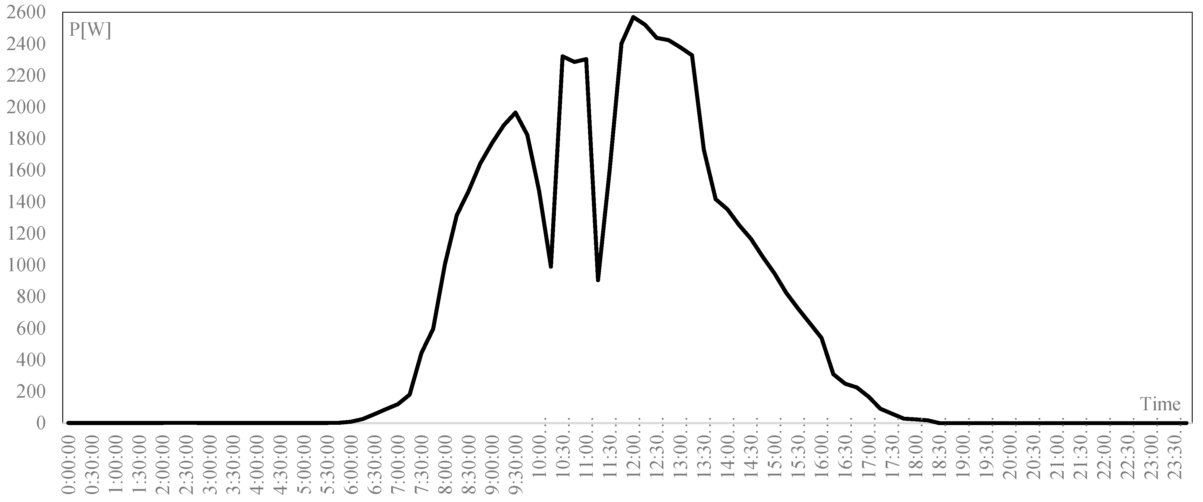
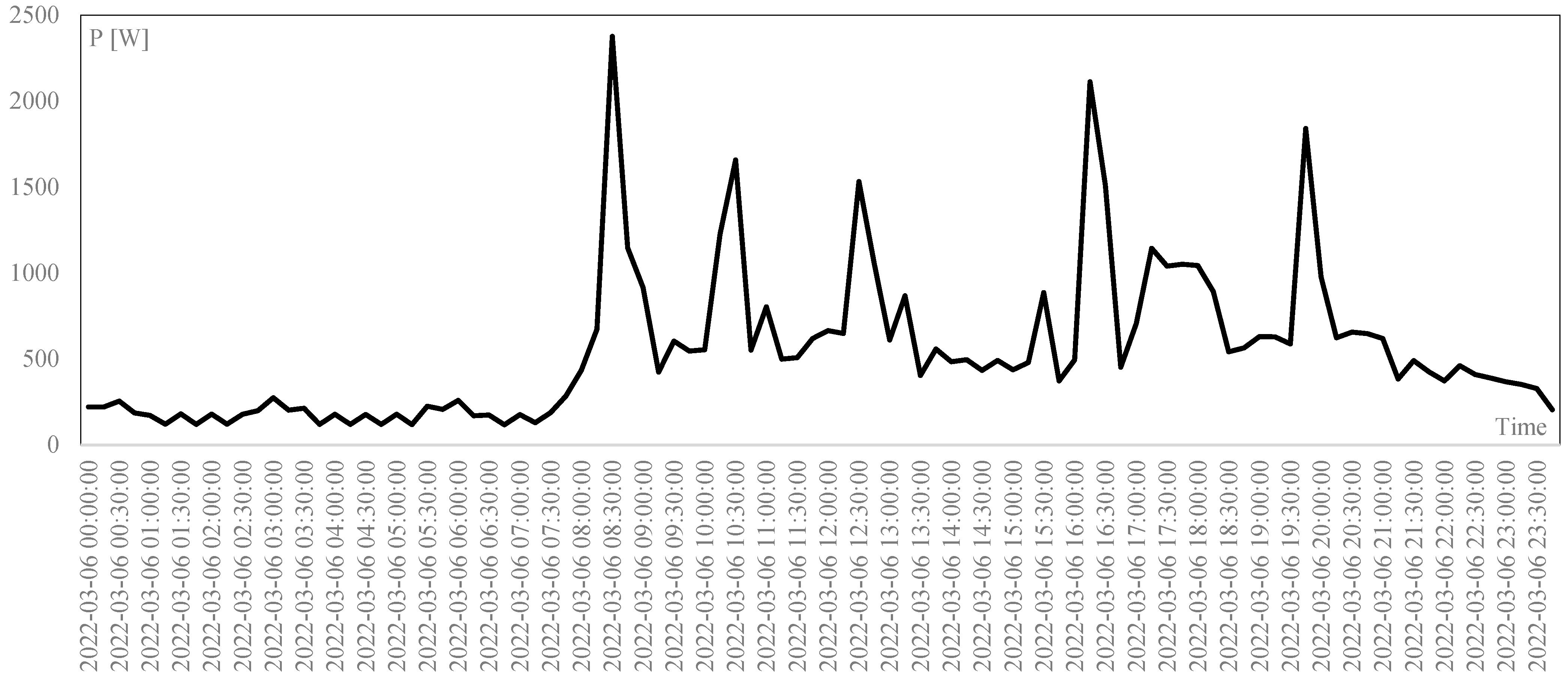
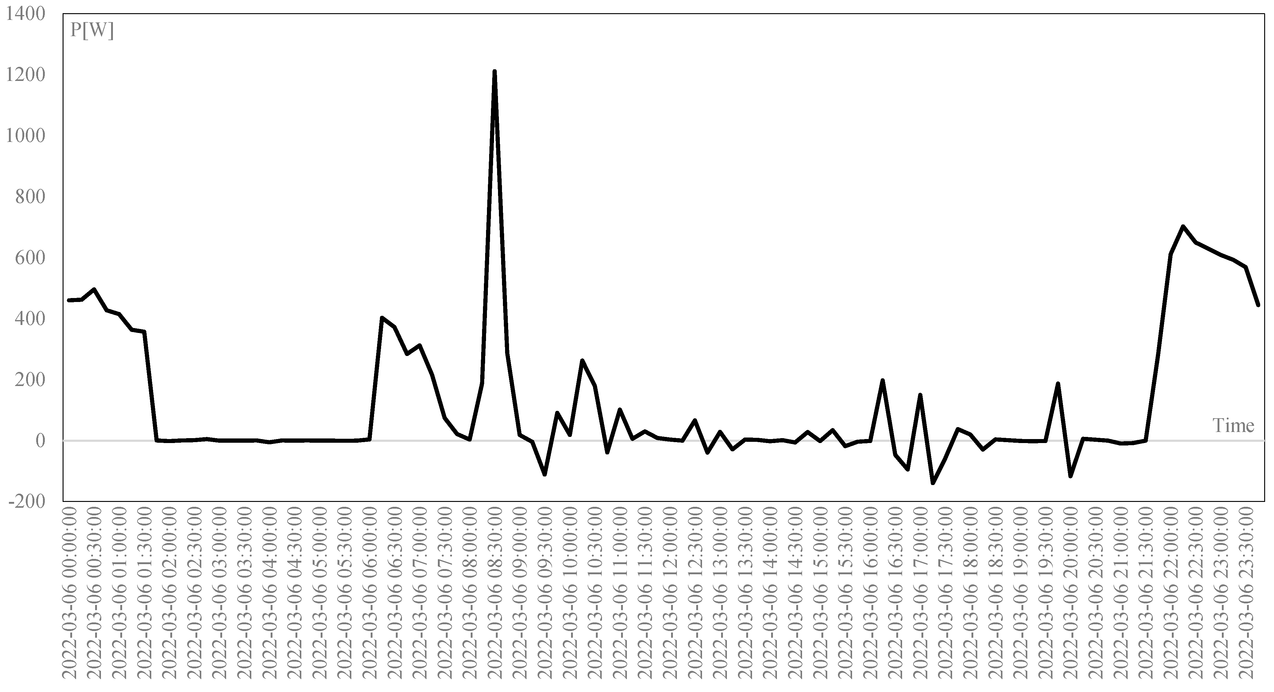
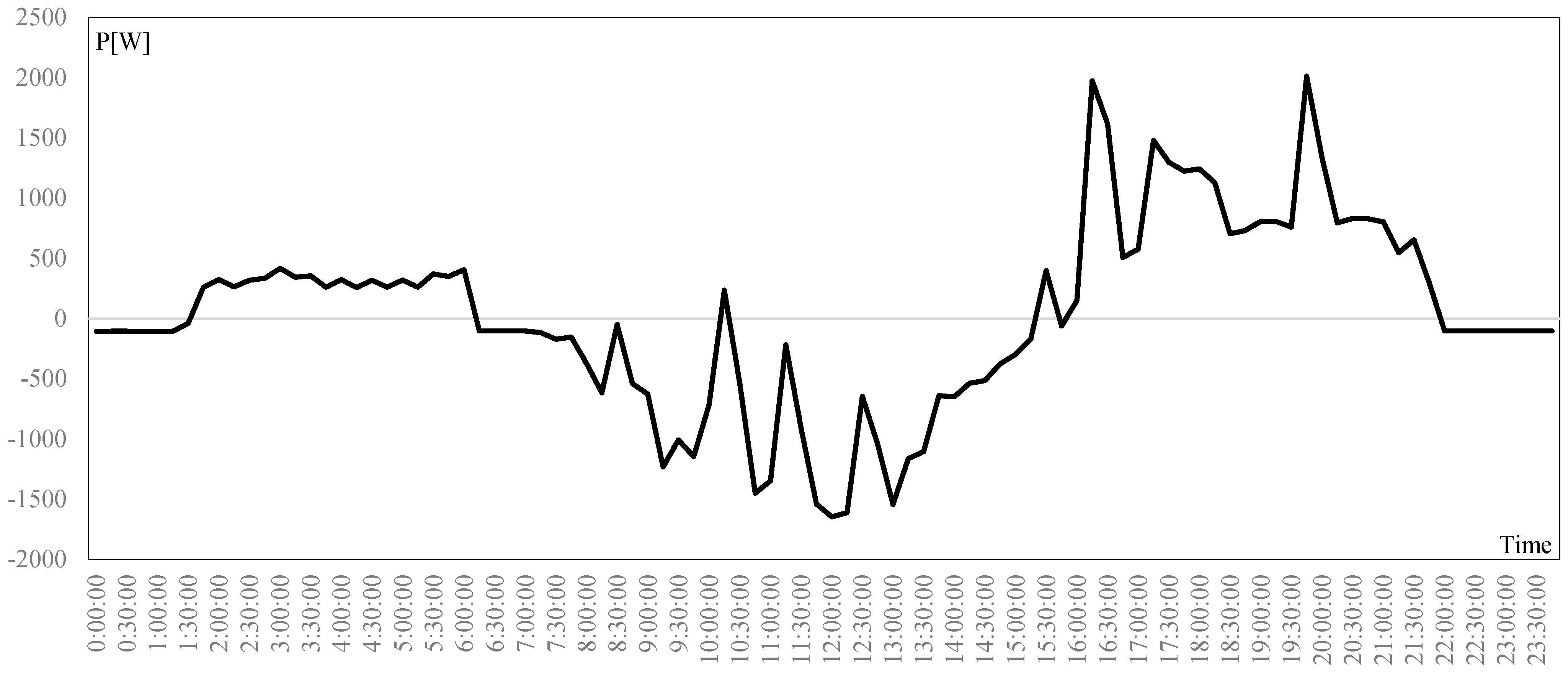
The PV, the load power profiles and the power exchanged between the grid and the AEU are reported in
Figure 11,
Figure 12 and
Figure 13. The power exchanged between the grid and the grid should be equal to zero (
Figure 13). In some time instances, such a net power profile is different from zero, due in particular to the exchanged ESS power. The ESS power profile and SOC are reported in
Figure 14 and
Figure 15.
In
Figure 16 the net power profile that the AEU would have exchanged with the grid without the use of the DCNG is reported. It has been numerically evaluated. It is lower than zero when there is a power surplus that has to be injected into the grid and vice versa when there is a power deficit. Therefore, power is required to supply the loads.
From
Figure 13, it can be observed that for almost the whole day, the AEU exchanges a power equal to zero with the grid. Only at the beginning of the day and at the end of the day are there withdrawals from the grid due to insufficient energy in the ESS.
In addition, there is a peak of absorption from the grid around 8.30 a.m. due to the high load power in that time interval and the reduced PV production, as the power that the ESS can supply is also limited.
During the day, the PV-produced energy is equal to 14.04 kWh. The stored energy is equal to 6.66 kWh, while the supplied energy from the battery is equal to 7.37 kWh. The energy absorbed by the loads is equal to 13.17 kWh. The energy absorbed from the grid that is not supplied by the DCNG is equal to 3.23 kWh. The surplus of PV-produced energy that is not stored in the ESS or used to supply the load is equal to 0.19 kWh.
With the proposed AEU configuration and the control and management performed by the DCNG, considering the actual grid energy generation mix, the emitted equivalent CO2 is equal only to 1.32 kg with respect to 5.4 kg emitted without the use of DCNG.
If the IAS is evaluated for the hours when there is PV generation, its average value is equal to 67%, with hourly peak values also equal to 100%.
Therefore, we can affirm that, when comparing
Figure 13 and
Figure 16, the AEU equipped with DCNG is able to minimize energy exchanges with the grid and take advantage of the available resources, and CO
2 emissions can also be reduced.
5.2. Test–UC_2
The UC_2 starts considering the AEU operating as described in the UC_1: the first aim is to maximize the self-production, but at the same time, the AEU communicates a flexibility availability equal to 200 W for every time (a quarter of an hour) of the day.
Based on that AEU availability, the grid operator sends the flexibility day requests as reported in
Table 2, where the reduction power request (upward flexibility) is reported with a negative sign, and vice versa for the increased power requests (downward flexibility).
In this UC, the AEU must operate accordingly, modifying its grid exchange power profile to satisfy as much as possible the flexibility service requests.
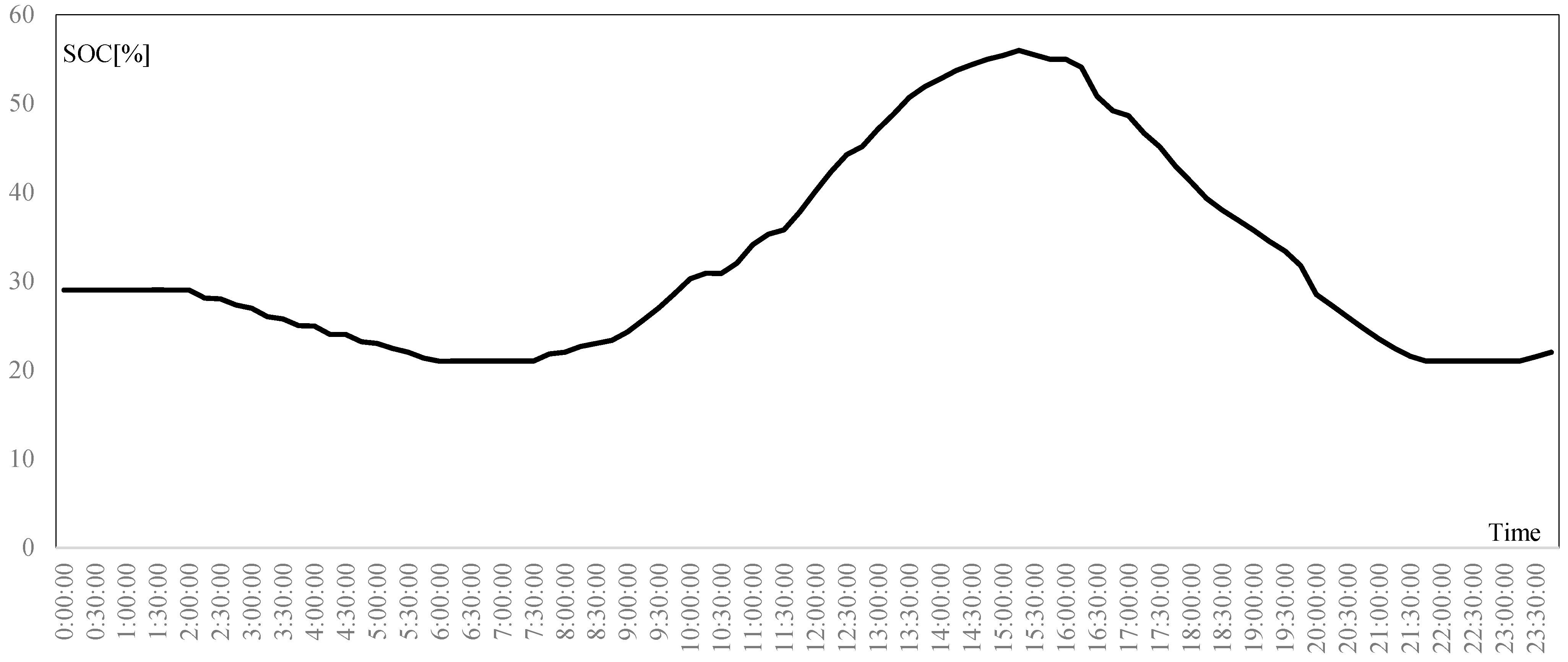
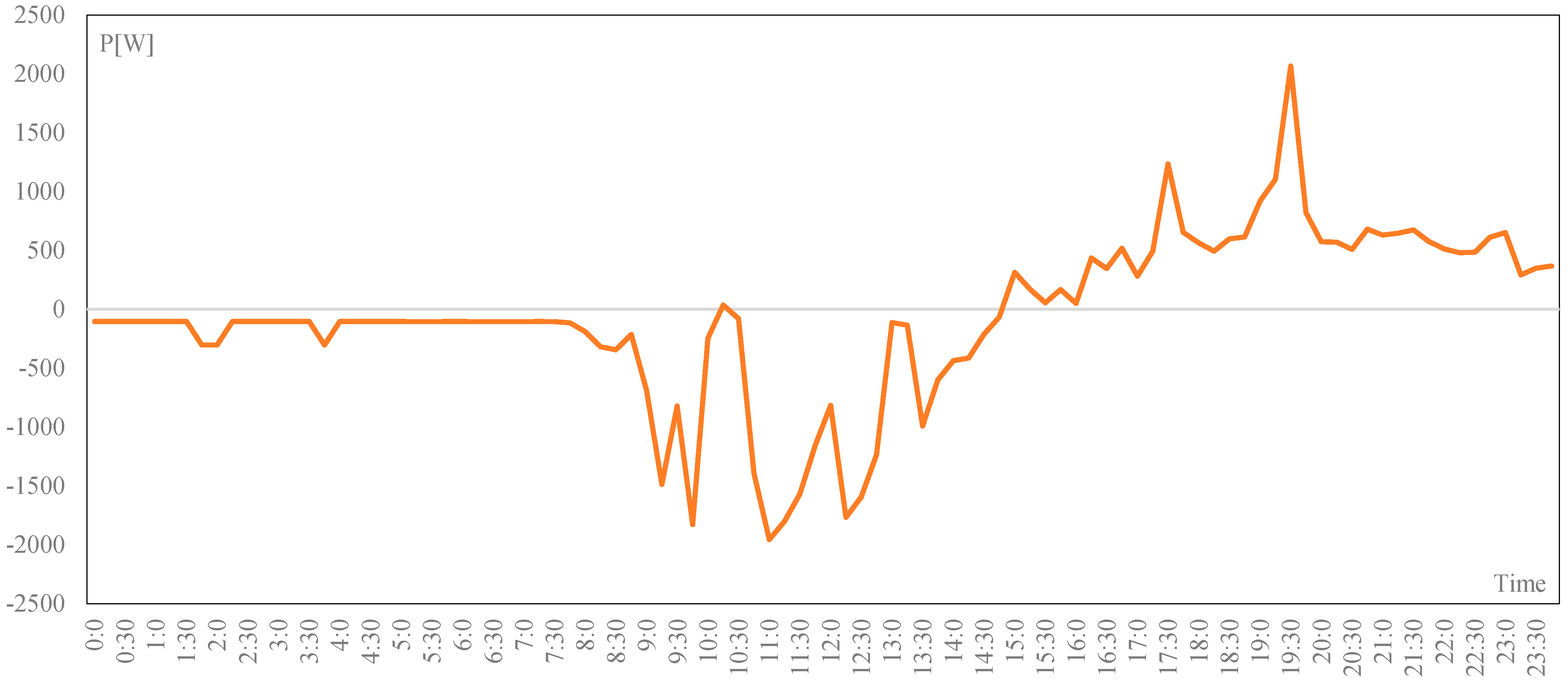
In
Figure 17, the power profile exchanged is reported. It can be observed that in the first part of the day, the net exchanged power is different from zero. This is due to the low SOC of the ESS, which does not allow to supply all loads. The flexibility requests are satisfied using the ESS; in particular, the required power is injected or absorbed by the ESS.
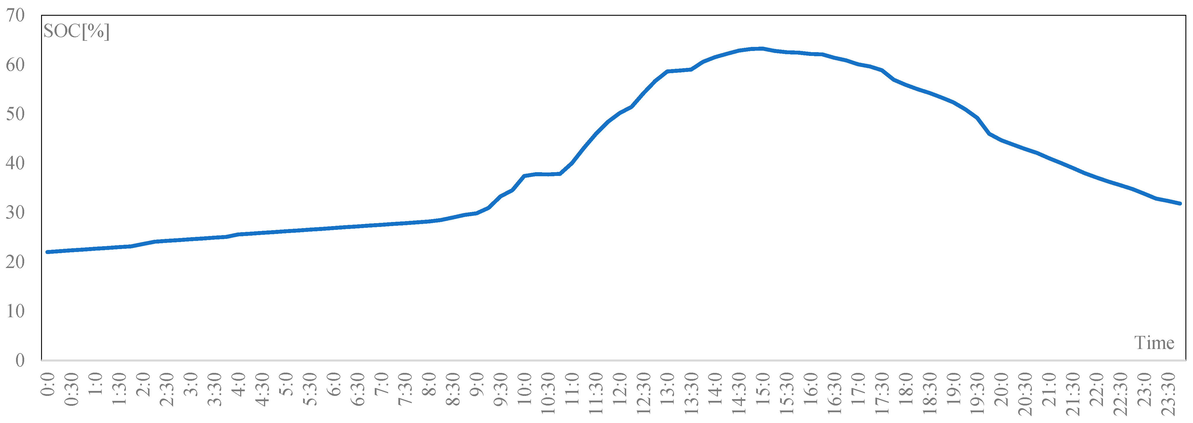
In
Figure 18 and
Figure 19, the ESS power and the SOC profile are reported. The ESS is unable to follow the load profile at the beginning of the day because of the low SOC; in the same way, it is unable to perform any requests for flexibility.
During the day, the total power for downward and upward flexibility requests are, respectively, 0.3 kWh and 0.287 kWh. All the upward flexibility requests have been satisfied, while the downward flexibility requests are satisfied only at about 61%. This is an extreme case, but still possible, in which the AEU storage system is not ready to be able to satisfy the flexibility requests.
A way to avoid such problems is to reserve a capacity of ESSs only for these services or to use several AEUs operating in a REC as illustrated in UC3. In this way, the different requests can be provided by the other AEUs.
In this use case, evaluating the IAS for the hours when there is PV production, there is not an evident difference between the case where services are required and where services are not required; its average value is about 75%, with hourly peak values also equal to 100%.
The ISRR has been also calculated and it is equal to about 1.2%, which means that most of the flexibility requests have been satisfied.
Therefore, with this use case, the authors want to demonstrate that an AEU equipped with DCNG that manages an RES plant and a storage system is able to provide flexibility services. In fact, to demonstrate it, we can compare
Figure 17 starting from 11:00 am onwards with
Table 2. It is observed that the power exchange with the grid is zero (or almost) when there is no flexibility service request, while it is equal to the flexibility service requested in the other instances of time. However, to be able to respond to these services, it is necessary to have a storage system that does not have to be completely charged or discharged (see first hours of
Figure 17 and compare it with
Table 2; the flexibility service is not satisfied).
5.3. Test–UC_3
In this use case, four AEUs are assumed to be part of an REC. The main goal is to maximize the self-consumption. It is assumed that flexibility services are also requested from the grid operator, as illustrated in
Table 3.
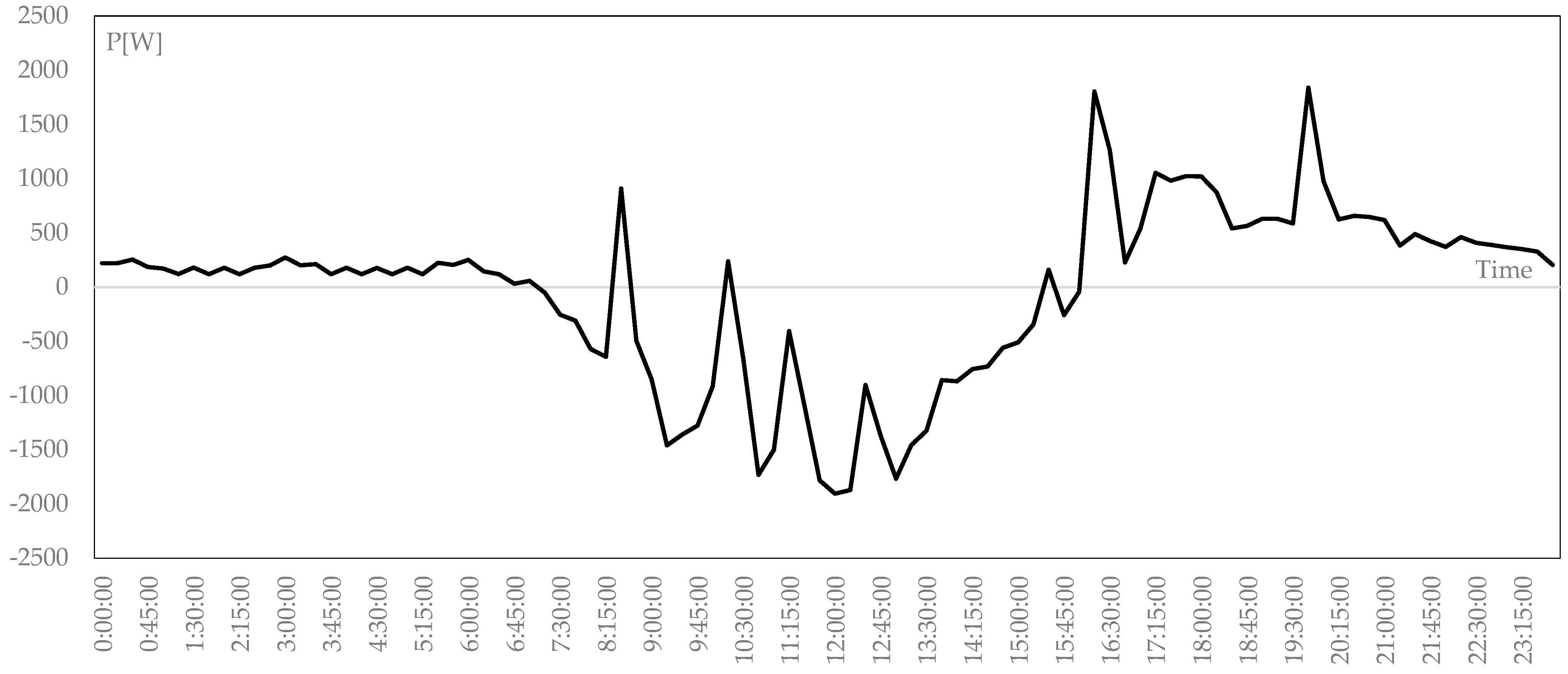
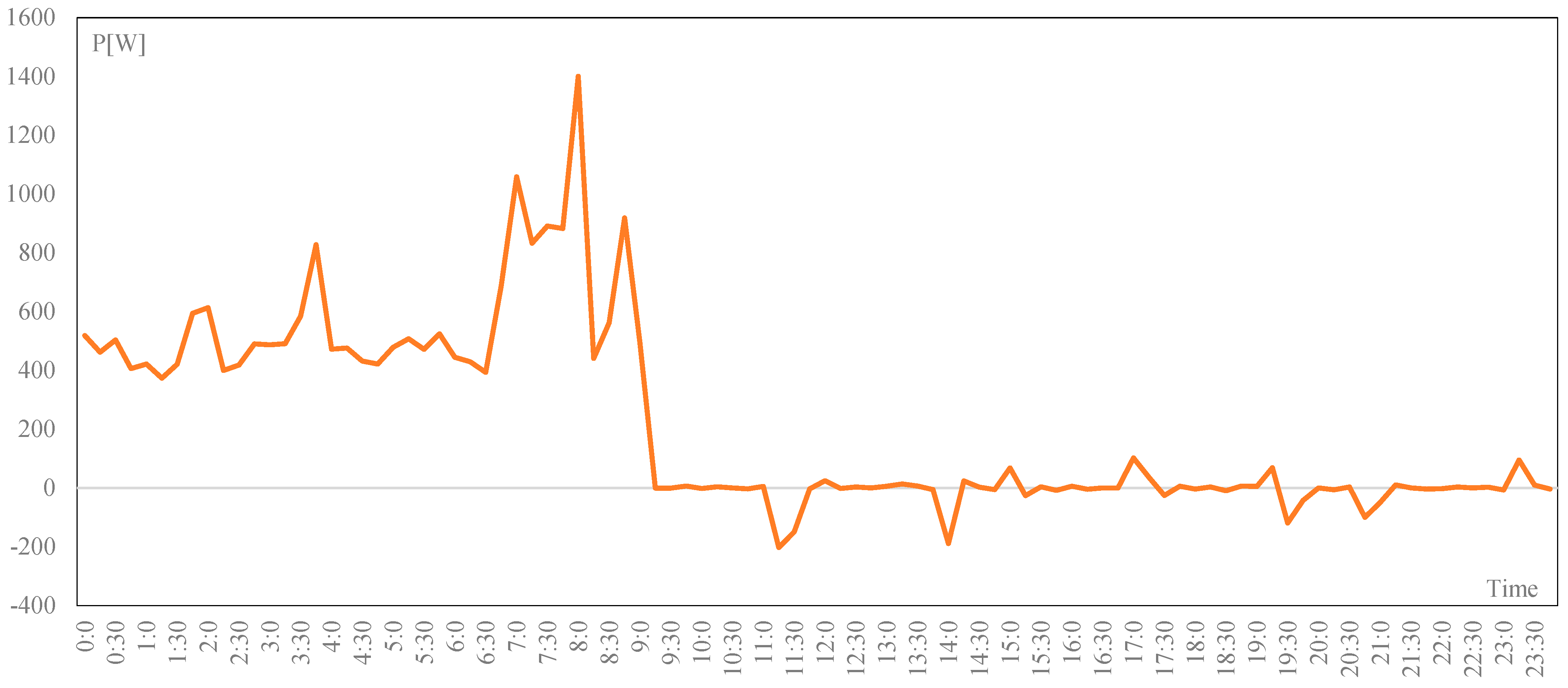
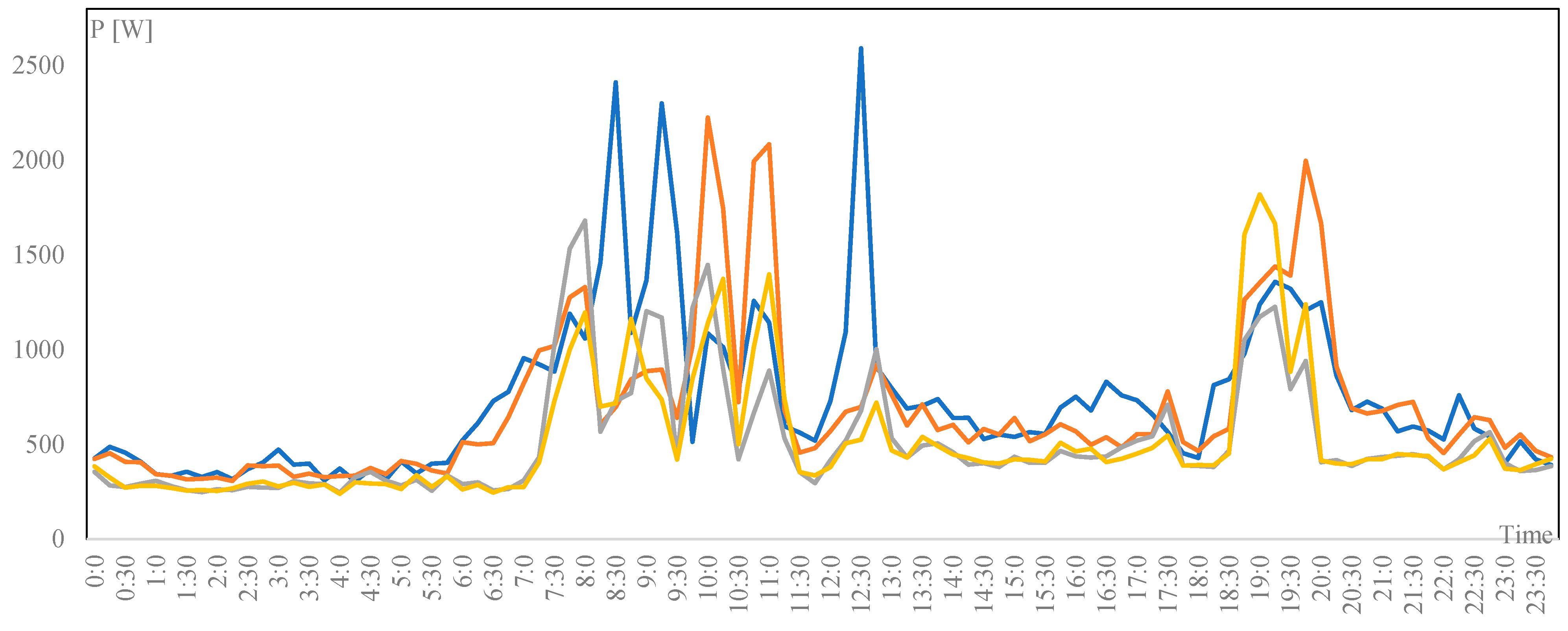
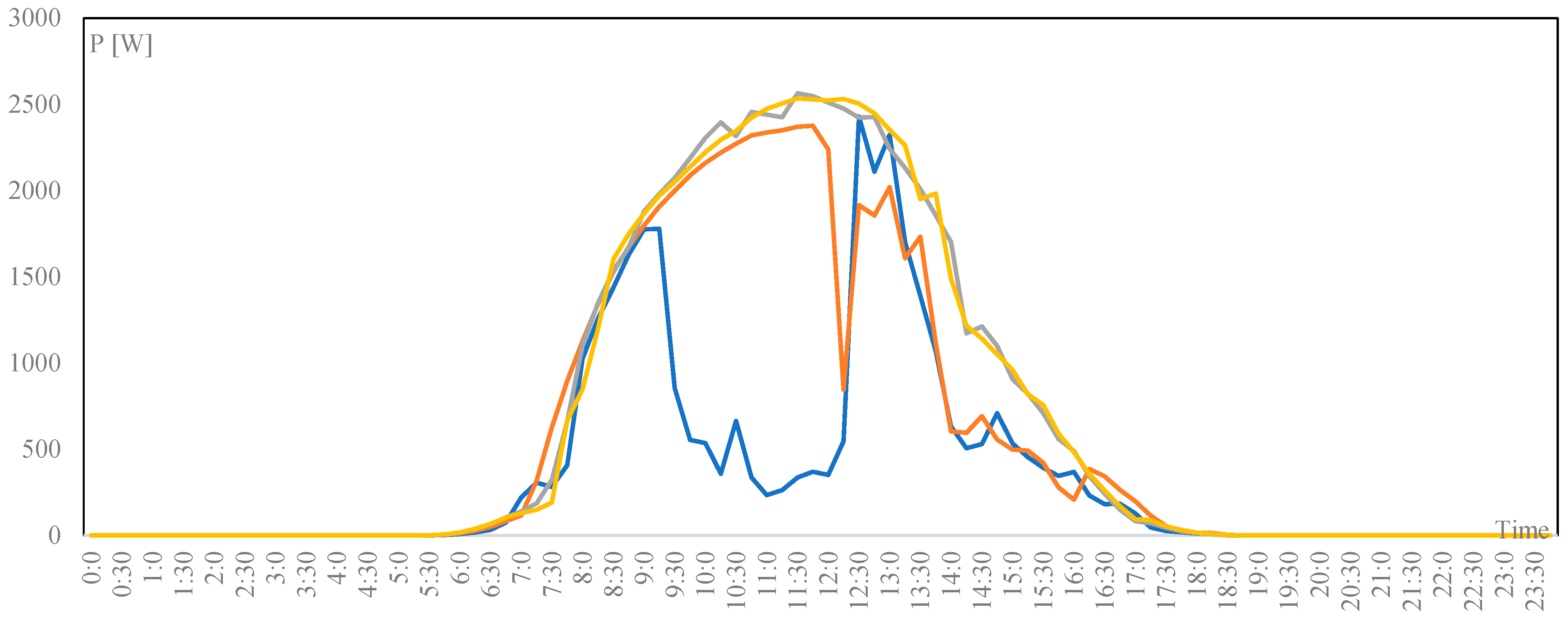
In
Figure 20,
Figure 21,
Figure 22 and
Figure 23, the load, the PV generation, the ESS power profiles of the four AEUs and the REC net power profile exchanged with the grid are reported. The last one is equal to zero when no flexibility request is present. Otherwise, it is equal to the request.
Each specific flexibility request is distributed to each AEU by dividing the power request in proportion to the capacity of the ESS associated with each single AEU.
As can be seen from the numerical results, in terms of the power exchanged with the grid, the operation of AEUs as an REC allows to maximize the self-consumption as well as to satisfy flexibility requests using the ESSs appropriately.
This is evident from
Figure 23. In fact, this profile is null (or almost) when there is no request for a flexibility service, as the REC maximizes self-consumption, while the profile is non-zero when there is a service request, and the profile is equal to the request (see
Table 3). This is possible by exploiting all the resources, RES
Figure 21 and ESS
Figure 22, of the REC.
The hourly IAC has been evaluated for the hours where the PV production is greater than zero: it ranges between 93.7% and 100%; its average value is about 99.3%. These values are due to the optimal operation of the storage systems.
The ISRR is quite null, which means overall flexibility requests at the REC level have been satisfied.
6. Conclusions
Globally, many states, including Italy, are committed to undertaking an effective and sustainable path of deep decarbonization in all sectors through a profound restructuring of energy systems. This has led to the need for new management models to maximize the use of energy produced from renewable sources, ensuring safety conditions, continuity of service and resilience of the electricity system itself.
Possible reference models are that of the Renewable Energy Communities (REC) and the Citizen Energy Communities (CEC). In particular, the model based on CERs was taken as a reference by the European Commission—with the Directive (EU) 2018/2001 (called RED II) recently implemented by the Italian Government on 15 December 2021 with Legislative Decree 199—to allow participation active consumer in the energy transition through the sharing of electricity produced from renewable sources, the promotion of energy efficiency and, therefore, the spread of electric mobility. CERs have been introduced to maximize the use of energy from renewable sources and minimize energy costs for users.
This paper, in this contest, illustrates the main enabling technologies, smart meter, ESS, DCNG and ECM platform, that must be used to support the growth of RECs. The innovative settlement of the Advanced End-User is introduced, defined as an active and pro-active end-user equipped with the above-mentioned enabling technologies.
Finally, some use cases and the associated performance indexes have been identified and defined, respectively. The numerical results performed both, considering the operation of a single AEU and four AEUs operating as an REC, are illustrated, and discussing when flexibility service requests are sent or not, highlighting how it is possible to both maximize the self-consumption and satisfy the flexibility service request in the case of an REC consisting of AEUs as members.
Through the analysis and comparison of the different considered UCs, it was possible to demonstrate the importance of the individual technologies and their combined use as enabling elements for RECs. UC1 shows how the use of the proposed technologies increases self-consumption. This increase is measured through IAS which goes from a virtual average value of 15% to that of 67%. On the other hand, the comparison between UC1 and UC2 shows that, in the case of a single AEU, there is not an obvious difference between the cases where services are required and where services are not required. Finally, UC3 demonstrates that the community use of the above technologies enables further performance measured by means of IAC, of which the average value is about 99.3%.


 ,
, 


