
Design and Optimization Technologies of Permanent Magnet Machines and Drive Systems Based on Digital Twin Model


Abstract
:1. Introduction
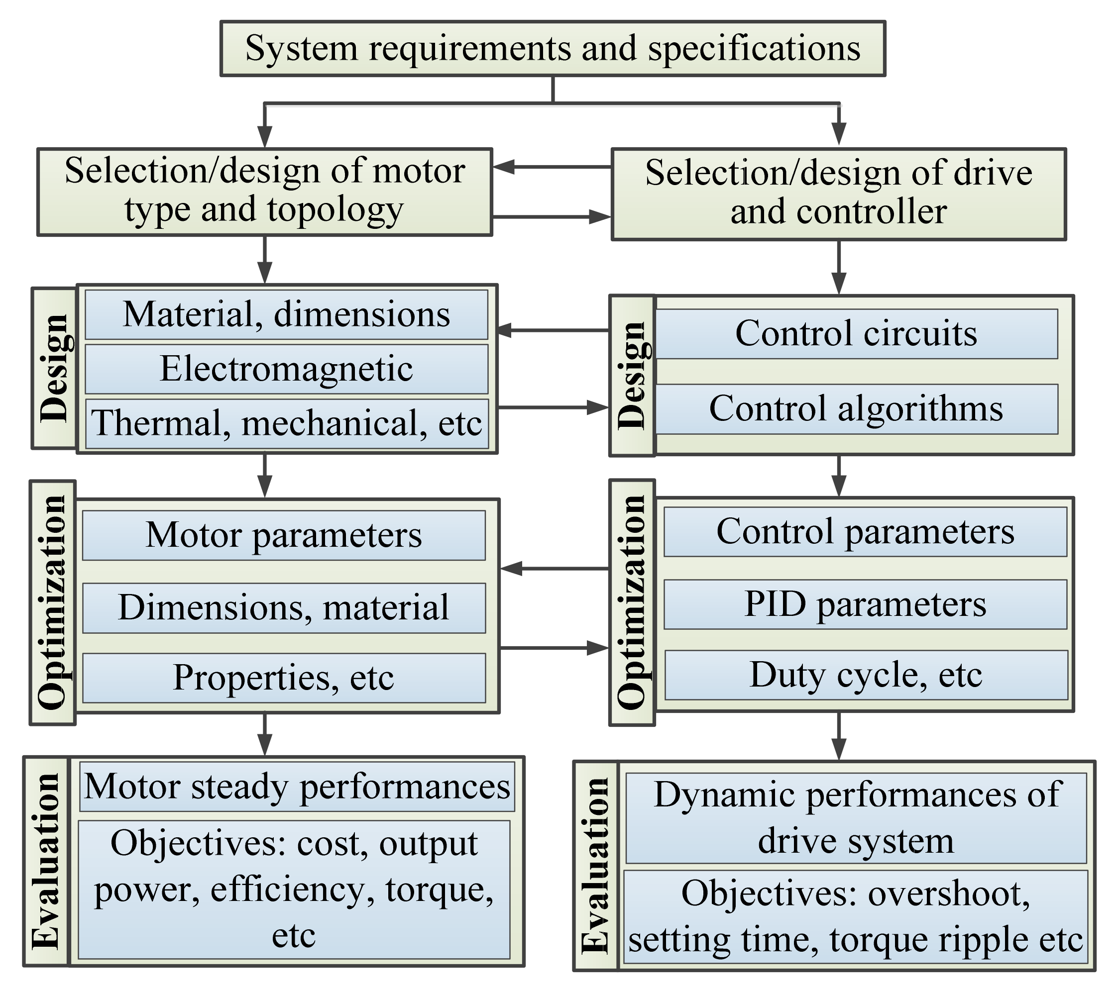
2. Design Technologies of HSPMM and Drive Systems
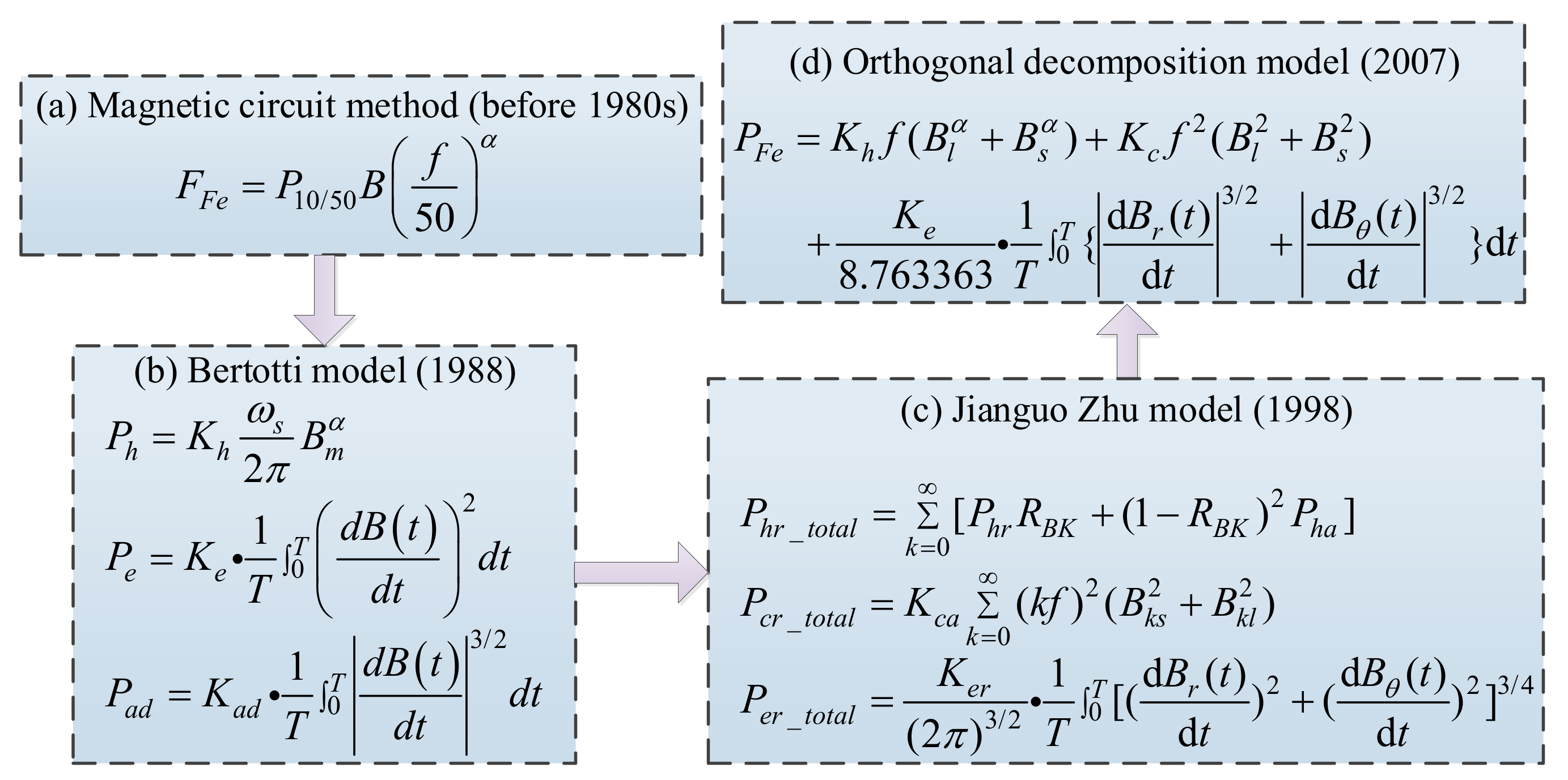
2.1. Power Losses
2.2. Thermal Design
2.3. Mechanical Characteristics
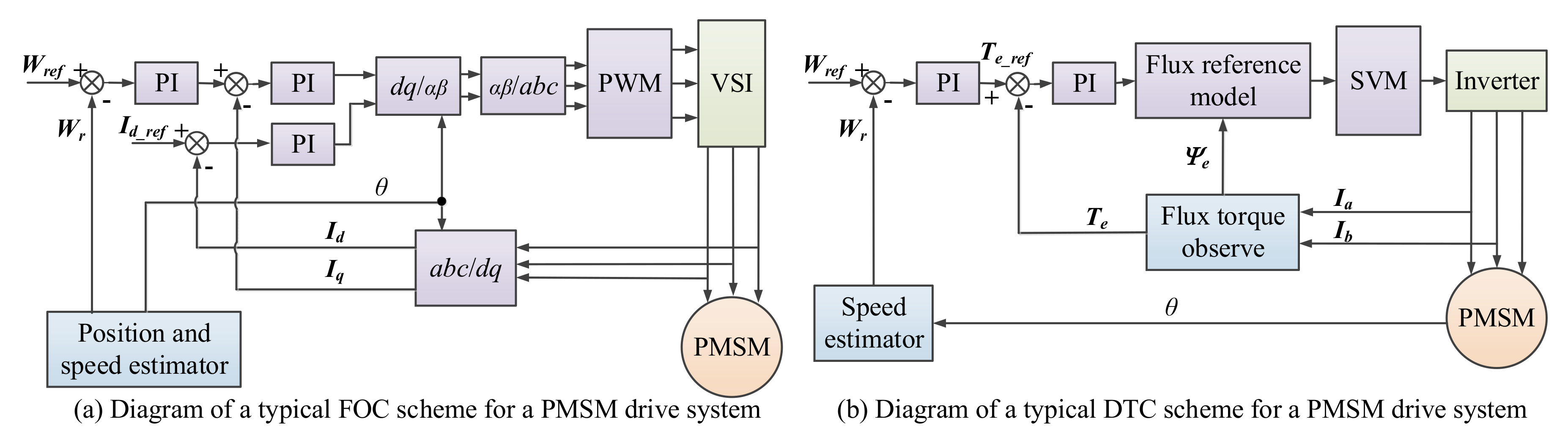
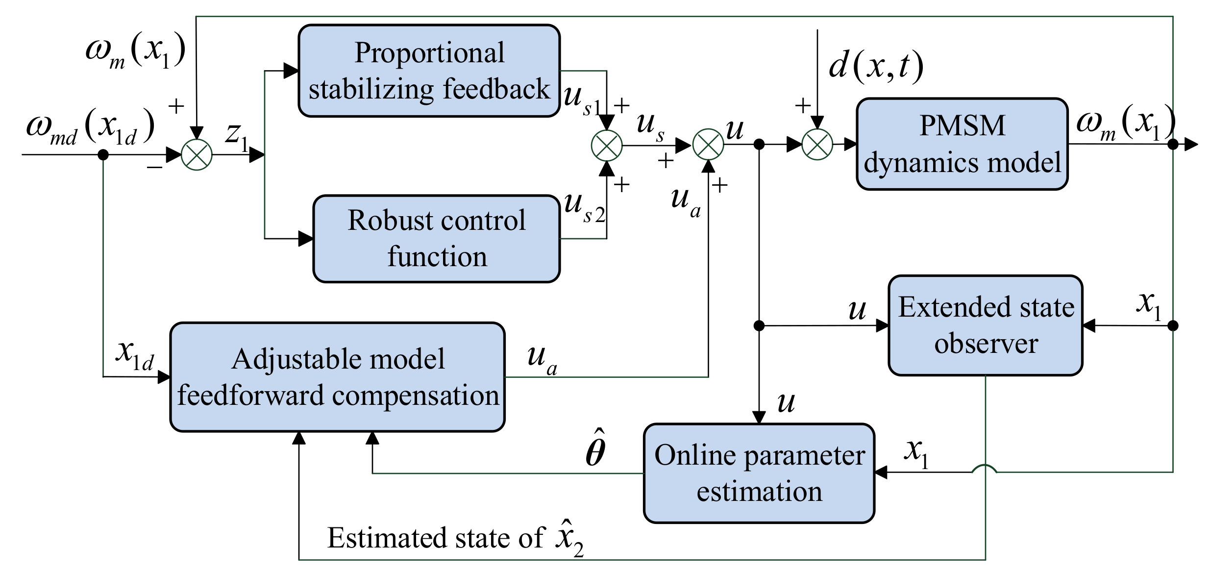
2.4. Control Methods/Strategies
3. Digital Twin
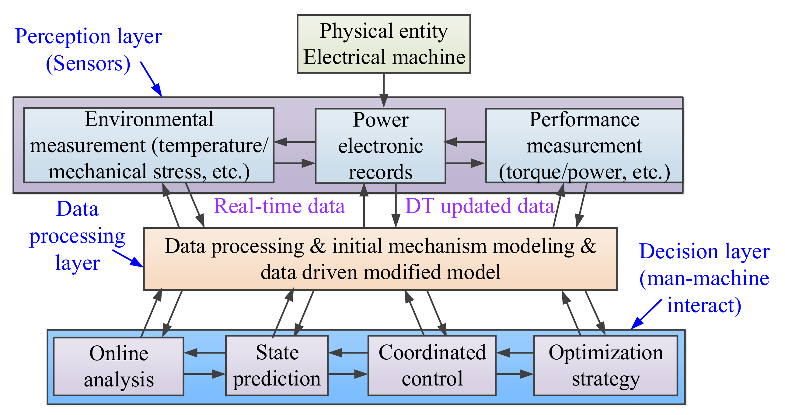
3.1. System Physical Entity Layer
3.2. Data Perception Layer
- (1)
- Developing highly reliable advanced sensors for complex working conditions and environments. When the electrical drive systems operate at conditions of excessive temperature or excessive pressure, the sensors should nevertheless maintain the traits of miniaturization, low power consumption, little delay in communication and high-precision time synchronization, etc.
- (2)
- Realizing multi-faceted and overall in-depth monitoring. An electrical drive system is a multi-coupling system in the fields of electricity, magnetism, heat, force and sound. Many parameters can be difficult to observe or measure directly, such as magnetic field distributions and losses.
- (3)
- Improving the accuracy of collected data. Due to the different sensor types and working environments, the current and voltage records gathered with the aid of the sensor are prone to harmonic interference with large noise. The low-quality data will cause the system to misjudge or pass over the operating state, affecting the accuracy of the DT models. The accumulated online statistics have to be similarly processed via data cleaning and other operations to enhance the information amount and supply a dependable statistics foundation for the building of DT models.
3.3. Data Processing Layer
3.4. Decision-Making Layer
3.5. General Technique Route
- (1)
- The DT is initialized with the current state of the physical entity of electrical drive systems, so that the initial conditions of the DT and the physical entity are consistent. By customizing various working conditions according to research needs, simulation software is used to provide unobservable training and test data for intelligent algorithms. The initial training data set can then be obtained after data preprocessing, feature attribute selection and dimension reduction.
- (2)
- The processed data are introduced into the neural algorithms to train the models. In addition to the data-driven statistical correlation models, the differential algebraic models (mechanism models) also need to be integrated into the DT models, because the genes of DTs and physical entity are consistent.
- (3)
- Then, the physical entity is always in changing and developing, and constantly corrects its own structure and parameters in accordance with the real-time records from the sensors, in order to accurately reflect the state of the physical model in the virtual digital space.
- (4)
- The objectives of DTs in short term are predicted, while the optimal control strategies are selected simultaneously.
- (5)
- The optimization results obtained from the simulation are fed into the test entity to control the device, while the DTs will be improved simultaneously by using the updated running state data of electrical drive systems.
- (6)
- Another optimization and control strategy can be conducted in this section with the stakeholders’ advice. The same process as (5) will occur.
4. Fault Diagnosis and Optimization Strategy
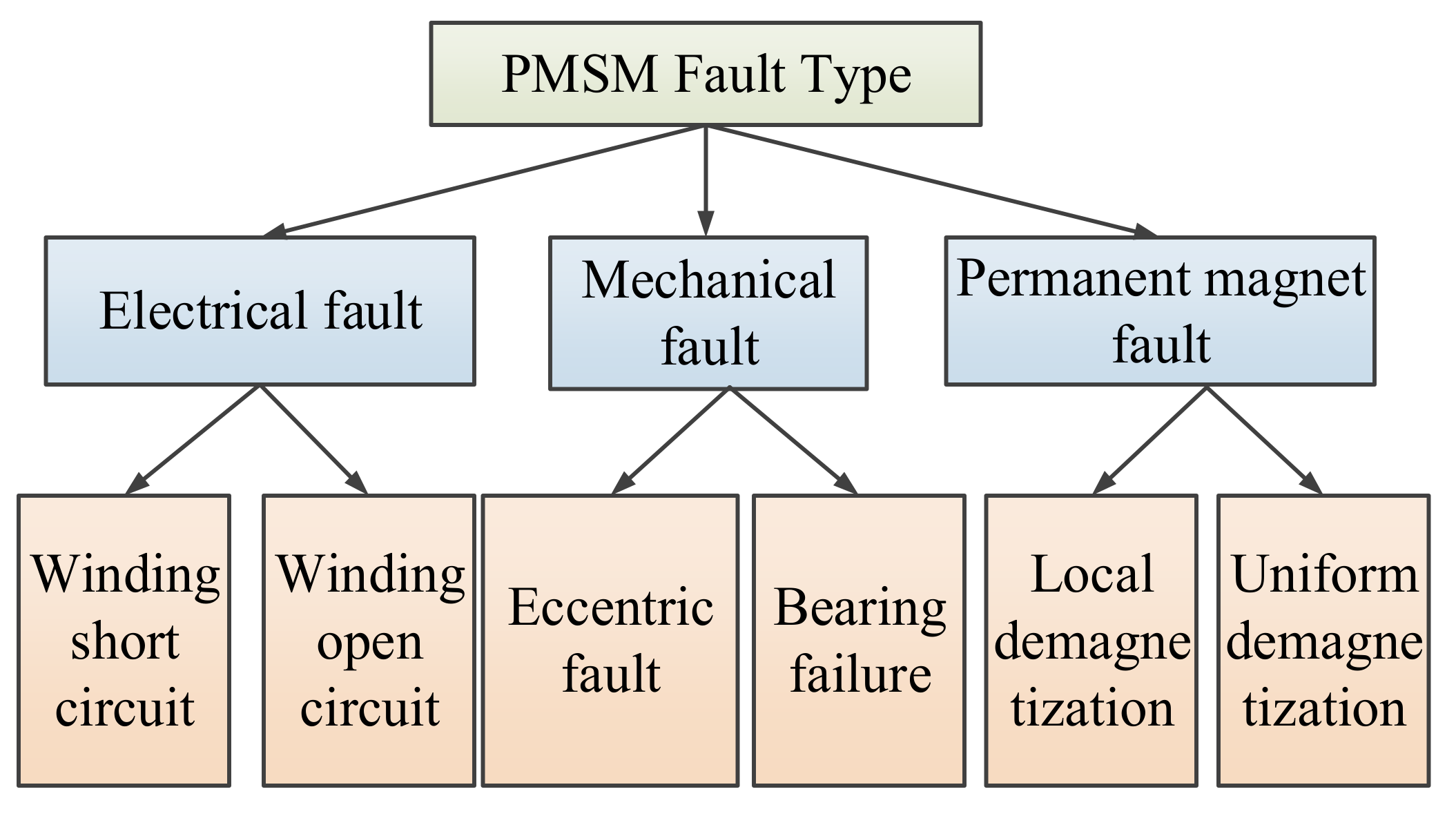
4.1. Fault Diagnosis
- (i)
- Direct analysis method
- (ii)
- Model analysis method
- (iii)
- Signal processing method
- (iv)
- Artificial intelligence method
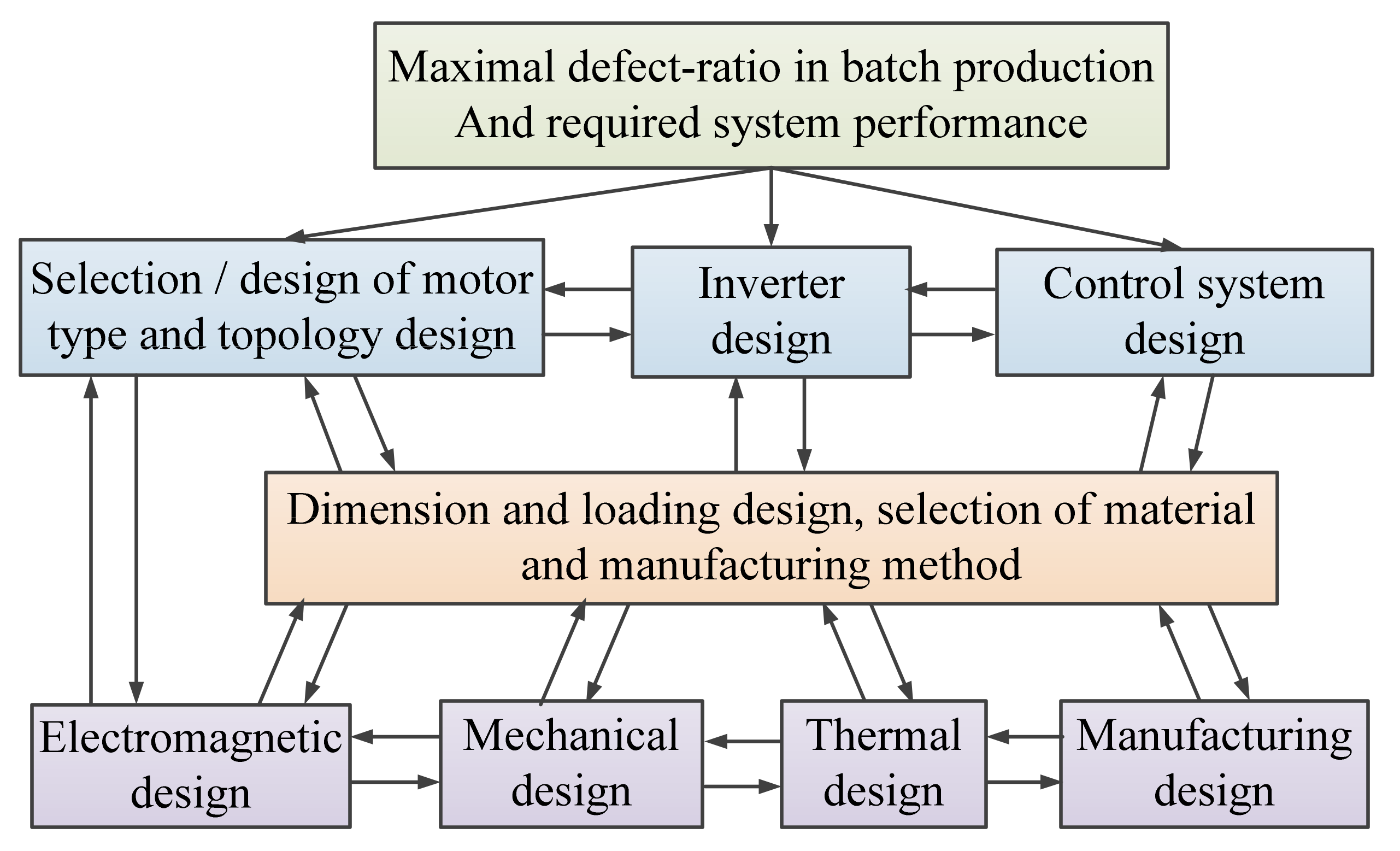
4.2. Design Optimization of HSPMM
4.2.1. Optimization Models
- (i)
- Multi-physics optimization model
- (ii)
- Multi-objective optimization model
- (iii)
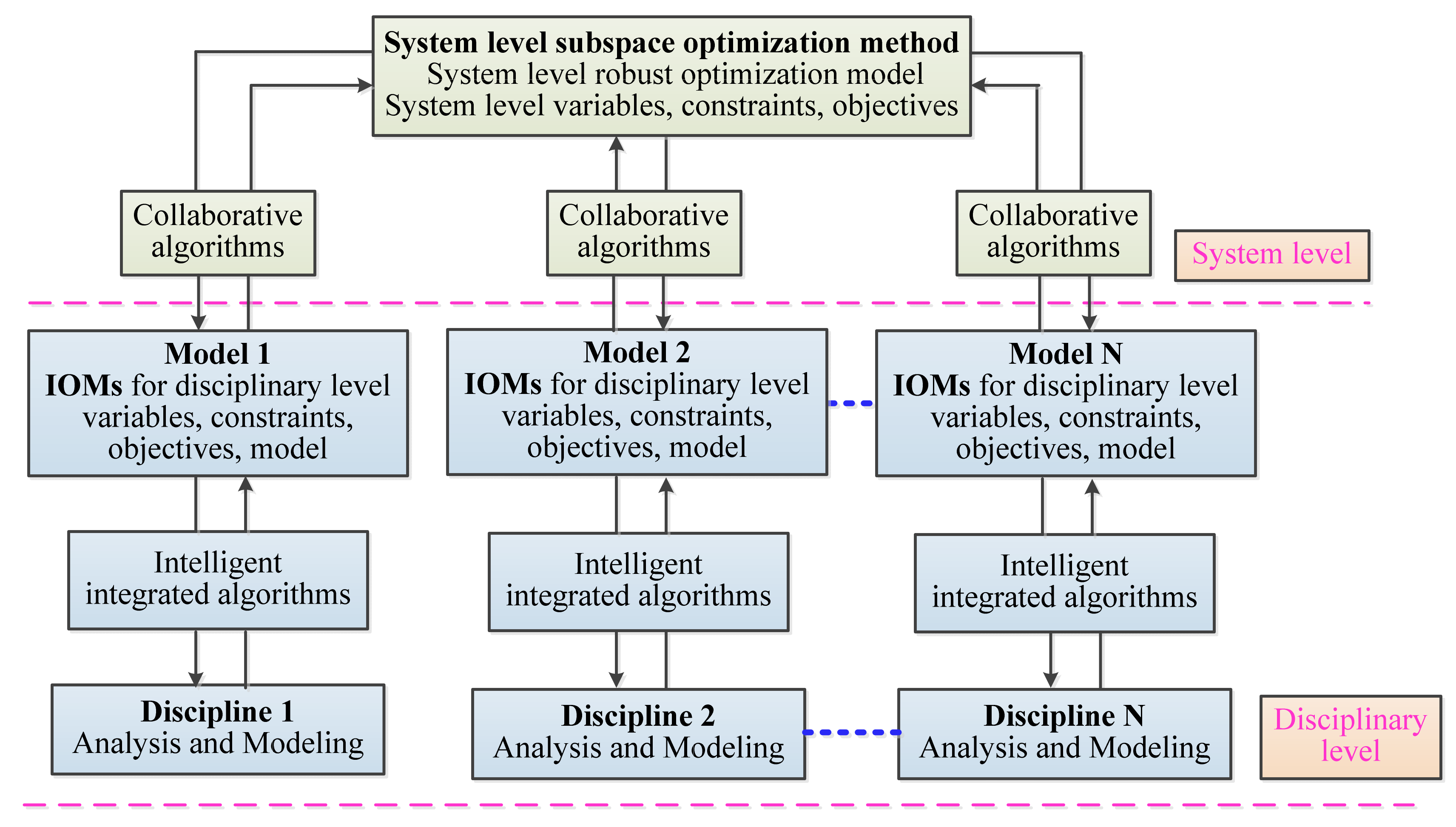
- System-level optimization model
- (iv)
- System-level optimization model
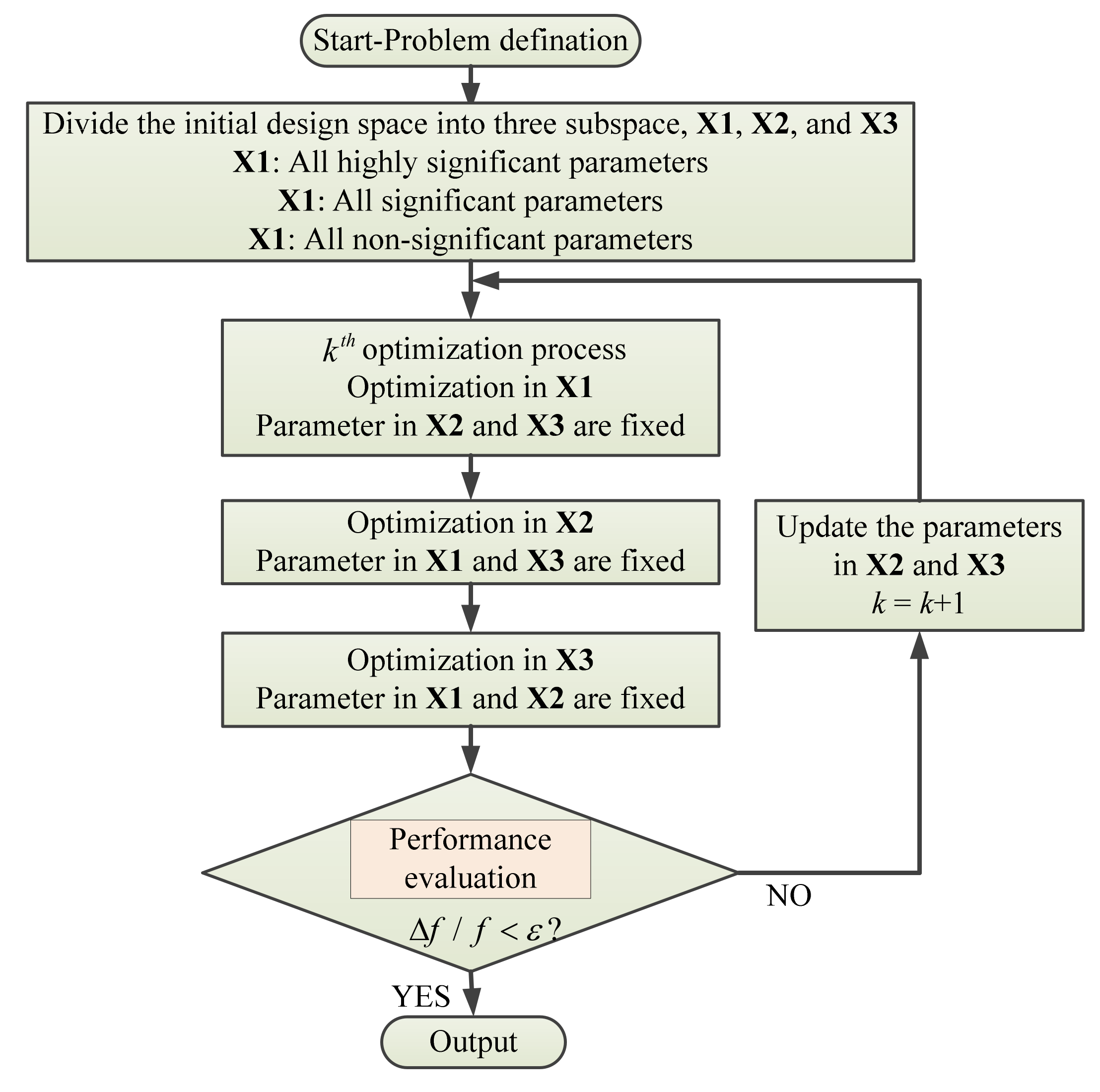
4.2.2. Optimization Methods/Strategies
- (i)
- Conventional optimization method
- (ii)
- Multi-level optimization method
- (iii)
- Multi-disciplinary optimization method
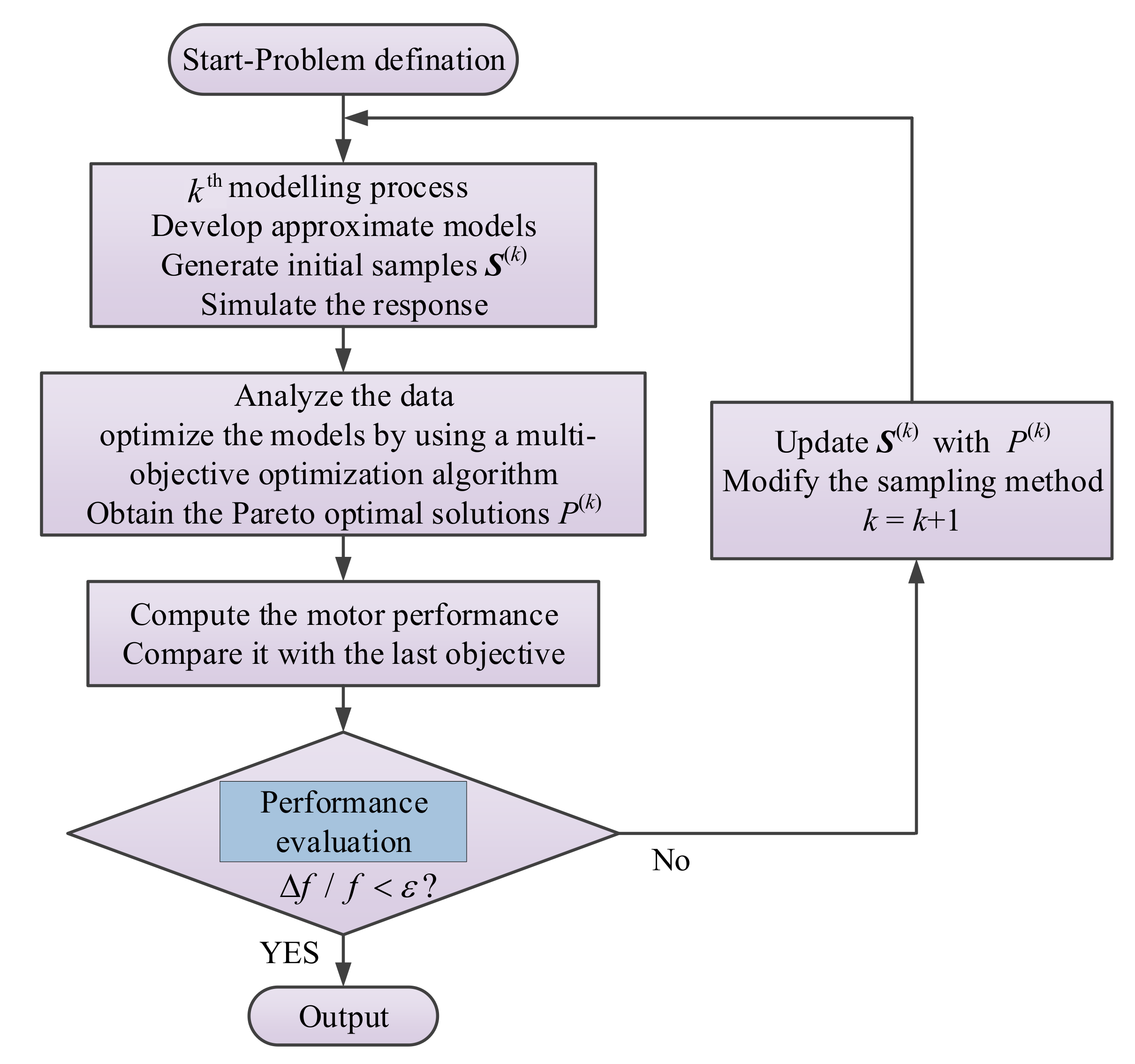
- (iv)
- Space reduction sequential optimization method
5. Conclusions and Future Directions
- (1)
- With the flourishing of involved areas such as intelligent algorithms, engineering automation tools and simulation methods, in the domain of electrical drive systems, we should leverage our expertise in electrical machines and their drive systems to develop DT models with multiscale and multi-operating modes for realizing system level and multidisciplinary modelling. To ensure the consistent state between the entity and the DT model, effort should be given to the combined modelling of mechanism and data, the special working conditions considered for improving the DT model database and the life prediction of key components.
- (2)
- Based on the PMSM drive system–DT technology, the coordinated control strategy served for system and subregion levels should be put forward. Improving the capability of optimal decision making regarding multiple timescales, multi-objective and multi-constraint will be another issue. Moreover, substantial work should also be done towards promoting the technologies concerning data perception, transmission and real-time processing & sharing.
- (3)
- It is necessary to tap into the potential information from massive data to deal with uncertainty, error, coupling interaction and other disturbances. Therefore, a series of services, such as fault diagnosis and detection, health management, state prediction, system control optimization, etc., will be greatly developed at the decision-making level, which will be beneficial to engineering efficiency, accuracy and practicality.
Author Contributions
Funding
Institutional Review Board Statement
Informed Consent Statement
Data Availability Statement
Conflicts of Interest
References
- Tang, N. Securing the Future of German Manufacturing Industry: Recommendations for Implementing the Strategic Initiative Industrie 4.0; Final Report of the Industrie 4.0 Working Group; Forschungsunion Stifterverband die Deutsche Wirtschaft e.V.: Berlin, Germany, 2013. [Google Scholar]
- Bajic, B.; Rikalovic, A.; Suzic, N.; Piuri, V. Industry 4.0 implementation challenges and opportunities: A managerial perspective. IEEE Syst. J. 2021, 15, 546–559. [Google Scholar] [CrossRef]
- Bhatia, M.S.; Kumar, S. Critical success factors of Industry 4.0 in automotive manufacturing industry. IEEE Trans. Eng. Manage. 2022, 69, 2439–2453. [Google Scholar] [CrossRef]
- Tao, F.; Qi, Q.; Wang, L.; Nee, A.Y.C. Digital twins and cyber–physical systems toward smart manufacturing and industry 4.0: Correlation and comparison. Eng. Forthcom. 2019, 5, 653–661. [Google Scholar] [CrossRef]
- Chhetri, S.R.; Faezi, S.; Canedo, A.; al Faruque, M.A. Quality inference from living digital twins in IoT-enabled manufacturing systems. In Proceedings of the International Conference on Internet of Things Design and Implementation, Montreal, QC, Canada, 15–18 April 2019; pp. 237–248. [Google Scholar]
- Jeong, D.-Y.; Baek, M.-S.; Lim, T.-B.; Kim, Y.-W.; Kim, S.-H.; Lee, Y.-T.; Jung, W.-S.; Lee, I.-B. Digital Twin: Technology evolution stages and implementation layers with technology elements. IEEE Access 2022, 10, 52609–52620. [Google Scholar] [CrossRef]
- Grieves, M. Virtually Intelligent Product Systems: Digital and Physical Twins; Springer: Berlin/Heidelberg, Germany, 2017. [Google Scholar]
- Barricelli, B.R.; Casiraghi, E.; Gliozzo, J.; Petrini, A.; Valtolina, S. Human digital twin for fitness management. IEEE Access 2020, 8, 26637–26664. [Google Scholar] [CrossRef]
- Dang, H.V.; Tatipamula, M.; Nguyen, H.X. Cloud-based digital twinning for structural health monitoring using deep learning. IEEE Trans. Ind. Inform. 2022, 18, 3820–3830. [Google Scholar] [CrossRef]
- Pu, T.; Chen, S.; Zhao, Q.; Wang, X.; Zhang, D. Framework design and application prospect for digital twins system of energy internet. Proc. CSEE 2021, 41, 2012–2029. [Google Scholar]
- Song, X.; Cai, H.; Kircheis, J.; Jiang, T.; Schlegel, S.; Westermann, D. Application of digital twin assistant-system in state estimation for inverter dominated grid. In Proceedings of the 55th International Universities Power Engineering Conference (UPEC), Turin, Italy, 1–4 September 2020. [Google Scholar]
- Jain, P.; Poon, J.; Singh, J.P.; Spanos, C.; Sanders, S.R.; Panda, S.K. A digital twin approach for fault diagnosis in distributed photovoltaic systems. IEEE Trans. Power Electron. 2020, 35, 940–956. [Google Scholar] [CrossRef]
- Sun, R.; Wang, L.; Wang, Y.; Ding, R.; Xu, H.; Wang, J.; Li, Q. Ultra-short-term prediction of photovoltaic power generation based on digital twins. Power Syst. Tech. 2021, 25, 1–9. [Google Scholar]
- Saad, A.; Faddel, S.; Youssef, T.; Mohammed, O.A. On the implementation of IoT-based digital twin for networked microgrids resiliency against cyber attacks. IEEE Trans. Smart Grid. 2020, 11, 5138–5150. [Google Scholar] [CrossRef]
- Grieves, M. Digital Twin: Manufacturing Excellence through Virtual Factory Replication, White Paper. 2014. Available online: http://www.apriso.com/library/Whitepaper_Dr_Grieves_DigitalTwin_ManufacturingExcellence.php (accessed on 1 March 2015).
- Zhang, Y.; McLoone, S.; Cao, W.P. Power loss and thermal analysis of a MW high speed permanent magnet synchronous machine. IEEE Trans. Energy Convers. 2017, 32, 1468–1478. [Google Scholar] [CrossRef]
- Liu, L.; Guo, Y.; Lei, G.; Zhu, J.G. Iron loss calculation for high-speed permanent magnet machines considering rotating magnetic field and thermal effects. IEEE Trans. Appl. Supercon. 2021, 31, 1–5. [Google Scholar] [CrossRef]
- Huang, Y.K.; Zhu, J.G.; Guo, Y.G. Thermal analysis of high-speed SMC motor based on thermal network and 3-D FEA with rotational core loss included. IEEE Trans. Magn. 2009, 45, 4684–4687. [Google Scholar]
- Wu, X.; Wang, X. Calculation of skin effect for double-cage rotor bar of the induction machine. Proc. CSEE 2003, 23, 116–120. [Google Scholar]
- Aglen, O. Loss calculation and thermal analysis of a high-speed generator. In Proceedings of the IEEE International Electric Machines and Drives Conference (IEMDC), Madison, WI, USA, 1–4 June 2003; pp. 1117–1125. [Google Scholar]
- Yin, Y.; Li, L. Improved method to calculate the high-frequency eddy currents distribution and loss in windings composed of round conductors. IET Power Electron. 2017, 10, 1494–1503. [Google Scholar] [CrossRef]
- Bertotti, G. General properties of power losses in soft ferromagnetic materials. IEEE Trans. Magn. 1988, 24, 621–630. [Google Scholar] [CrossRef]
- Zhu, J.G.; Ramsden, V.S. Improved formulations for rotational core losses in rotating electrical machines. IEEE Trans. Magn. 1988, 34, 2234–2242. [Google Scholar]
- Štumberger, B.; Hamler, A.; Goričan, V.; Jesenik, M.; Trlep, M. Accuracy of iron loss estimation in induction motors by using different iron loss models. J. Magn. Magn. Mater. 2004, 276, 1723–1725. [Google Scholar] [CrossRef]
- Jiang, S.L.; Zou, J.B.; Xu, Y.X. Variable coefficient iron loss calculating model considering rotational flux and skin effect. Proc. CSEE 2011, 31, 104–110. [Google Scholar]
- Liu, L.; Ba, X.; Guo, Y.; Lei, G.; Sun, X.; Zhu, J. Improved Iron loss prediction models for interior PMSMs considering coupling effects of multiphysics factors. IEEE Trans. Transp. Electr. 2022. Early Access. [Google Scholar] [CrossRef]
- Shisha, S.; Sadarangani, C. Analysis of losses in inverter fed large scale synchronous machines using 2D FEM software. In Proceedings of the 7th International Conference on Power Electronics and Drive Systems, Bangkok, Thailand, 27–30 November 2007; pp. 807–811. [Google Scholar]
- Zhao, N.; Zhu, Z.Q.; Liu, W. Rotor eddy current loss calculation and thermal analysis of permanent magnet motor and generator. IEEE Trans. Magn. 2011, 47, 4199–4202. [Google Scholar] [CrossRef]
- Yon, J.M.; Mellor, P.H.; Wrobel, R.; Booker, J.; Burrow, S.G. Analysis of semipermeable containment sleeve technology for high-speed permanent magnet machines. IEEE Trans. Energy Conver. 2012, 27, 646–653. [Google Scholar] [CrossRef]
- Xing, J.; Wang, F.; Zhang, D.; Kong, X. Research on rotor air friction loss of high-speed permanent magnet machines. Proc. CSEE 2010, 30, 14–19. [Google Scholar]
- Guo, B.; Huang, Y.; Guo, Y.; Zhu, J. Thermal analysis of the conical rotor motor using LPTN with accurate heat transfer coefficients. IEEE Trans. Appl. Supercon. 2016, 26, 0611507. [Google Scholar] [CrossRef]
- Dong, J.; Huang, Y.; Jin, L.; Lin, H.; Yang, H. Thermal optimization of a high-speed permanent magnet motor. IEEE Trans. Magn. 2014, 50, 749–752. [Google Scholar] [CrossRef]
- Nategh, S.; Huang, Z.; Krings, A.; Wallmark, O.; Leksell, M. Thermal modeling of directly cooled electric machines using lumped parameter and limited CFD analysis. IEEE Tran. Energy Convers. 2013, 28, 979–990. [Google Scholar] [CrossRef]
- Dong, B.; Wang, K.; Han, B.; Zheng, S. Thermal analysis and experimental validation of a 30 kW 60,000 r/min high-speed permanent magnet motor with magnetic bearings. IEEE Access 2019, 7, 92184–92192. [Google Scholar] [CrossRef]
- Dong, C.; Qian, Y.; Zhang, Y.; Zhuge, W. A Review of thermal designs for improving power density in electrical machines. IEEE Trans. Transp. Electr. 2020, 6, 1386–1400. [Google Scholar] [CrossRef]
- Gong, C.; Li, S.; Habetler, T. High-strength rotor design for ultra-high speed switched reluctance machines. IEEE Trans. Ind. Appl. 2020, 56, 1432–1442. [Google Scholar] [CrossRef]
- Le, Y.; Sun, J. Modeling and design of 3-DOF magnetic bearing for high-speed motor including eddy-current effects and leakage effects. IEEE Trans. Ind. Electron. 2016, 63, 3656–3665. [Google Scholar] [CrossRef]
- Reichert, T.; Nussbaumer, T.; Gruber, W.; Kolar, J.W. Bearingless permanent-magnet motor with 4/12 slot-pole ratio for bioreactor stirring applications. IEEE/ASME Trans. Mech. 2011, 16, 431–439. [Google Scholar] [CrossRef]
- Munteanu, G.; Binder, A. Loss measurement of a 40 kW high-speed bearingless PM synchronous motor. In Proceedings of the IEEE Energy Conversion Congress and Exposition, Phoenix, AZ, USA, 17–22 September 2011; pp. 722–729. [Google Scholar]
- Zhu, H.; Zhang, T. Finite element analysis for bearingless permanent magnet-type synchronous motors. Proc. CSEE 2006, 26, 136–140. [Google Scholar]
- Liao, Q.; Deng, Z.; Wang, X.; Qiu, Z.; Liu, Y.; Huang, Y. Suspension force pulse analysis of consequent-pole bearingless PM motor. Proc. CSEE 2007, 27, 49–54. [Google Scholar]
- Srinivas, K.N.; Arumugam, R. Static and dynamic vibration analyses of switched reluctance motors including bearings, housing, rotor dynamics, and applied loads. IEEE Trans. Magn. 2004, 40, 1911–1919. [Google Scholar] [CrossRef]
- Lei, G.; Zhu, J.G.; Guo, Y.G. Multidisciplinary Design Optimization Methods for Electrical Machines and Drive Systems; Springer: Berlin/Heidelberg, Germany, 2016; ISBN 978-3-662-49269-7. [Google Scholar]
- Blaschke, F. The principle of field orientation as applied to the new transvector closed- loop control system for rotating-field machines. Power Electron. 1972, 34, 217–219. [Google Scholar]
- Tang, Z.; Akin, B. A new LMS algorithm based deadtime compensation method for PMSM FOC drives. IEEE Trans. Ind. Appl. 2018, 54, 6472–6484. [Google Scholar] [CrossRef]
- Takahashi, I.; Ohmori, Y. High- performance direct torque control of an induction motor. IEEE Trans. Ind. Appl. 1989, 25, 257–264. [Google Scholar] [CrossRef]
- Zhong, L.; Rahman, M.F. Analysis of direct torque control in permanent magnet synchronous motor drives. IEEE Trans. Power Electron. 1997, 12, 528–536. [Google Scholar] [CrossRef]
- Perera, P.; Blaabjerg, F.; Pedersen, J.; Thogersen, P. A sensorless, stable V/f control method for permanent-magnet synchronous motor drives. IEEE Trans. Ind. Appl. 2003, 39, 783–791. [Google Scholar] [CrossRef]
- Wang, Z.; Zheng, Y.; Zou, Z.; Cheng, M. Position sensorless control of interleaved CSI fed PMSM drive with extended Kalman filter. IEEE Trans. Magn. 2012, 48, 3688–3691. [Google Scholar] [CrossRef]
- Xu, W.; Jiang, Y.; Mu, C.; Blaabjerg, F. Improved nonlinear flux observer-based second-order SOIFO for PMSM sensorless control. IEEE Trans. Power Electron. 2019, 34, 565–579. [Google Scholar] [CrossRef]
- Utkin, V.I. Sliding mode control design principles and applications to electric drives. IEEE Trans. Ind. Electron. 1993, 40, 23–36. [Google Scholar] [CrossRef]
- Melício, R.; Mendes, V.M.F.; Catalão, J.P.S. Fractional-order control and simulation of wind energy systems with PMSG/full-power converter topology. Energy Convers. Manag. 2010, 51, 1250–1258. [Google Scholar] [CrossRef]
- Rui, X.; Yin, W.; Dong, Y.; Lin, L.; Wu, X. Fractional-order sliding mode control for hybrid drive wind power generation system with disturbances in the grid. Wind Energy. 2019, 22, 49–64. [Google Scholar] [CrossRef]
- Yao, B.; Tomizuka, M. Adaptive robust control SISO nonlinear systems in a semi-strict feedback form. Automatica 1997, 33, 893–900. [Google Scholar] [CrossRef]
- Yao, B.; Tomizuka, M. Adaptive robust control of MIMO nonlinear systems in semi-strict feedback forms. Automatica 2001, 37, 1305–1321. [Google Scholar] [CrossRef]
- Yin, W.L.; Wu, X.; Rui, X.M. Adaptive robust backstepping control of the speed regulating differential mechanism for wind turbines. IEEE Trans. Sustain. Energy 2019, 10, 1311–1318. [Google Scholar] [CrossRef]
- Sun, X.; Wu, M.; Lei, G.; Guo, Y.; Zhu, J. An Improved model predictive current control for PMSM drives based on current track circle. IEEE Trans. Ind. Electron. 2021, 68, 3782–3793. [Google Scholar] [CrossRef]
- Huang, W.; Hua, W.; Fan, Q. Performance analysis and comparison of two fault-tolerant model predictive control methods for five-phase PMSM drives. CES Trans. Electr. Mach. Syst. 2021, 5, 311–320. [Google Scholar] [CrossRef]
- Barricelli, B.R.; Casiraghi, E.; Fogli, D. A survey on Digital Twin: Definitions, characteristics, applications, and design implications. IEEE Access 2019, 7, 167653–167671. [Google Scholar] [CrossRef]
- Chau, K.T.; Chan, C.C.; Liu, C. Overview of permanent-magnet brushless drives for electric and hybrid electric vehicles. IEEE Trans. Ind. Electron. 2008, 55, 2246–2257. [Google Scholar] [CrossRef]
- Rodriguez, J.; Garcia, C.; Mora, A.; Davari, A.; Rodas, J.; Garcia, D.F.V.; Elmorshedy, M.F.; Wang, F.; Zuo, K.; Tarisciotti, L.; et al. Latest advances of model predictive control in electrical drives—Part II: Applications and benchmarking with classical control methods. IEEE Trans. Power Electron. 2022, 37, 5047–5061. [Google Scholar] [CrossRef]
- Haque, T.S.; Rahman, H.; Islam, R.; Razzak, A.; Badal, F.R.; Ahamed, H.; Moyeen, S.I.; Das, S.K.; Ali, F.; Tasneem, Z.; et al. A Review on driving control issues for smart electric vehicles. IEEE Access 2021, 9, 135440–135472. [Google Scholar] [CrossRef]
- Ding, X.; Wang, Z.; Zhang, L.; Wang, C. Longitudinal vehicle speed estimation for four-wheel-independently-actuated electric vehicles based on multi-sensor fusion. IEEE Trans. Veh. Technol. 2020, 69, 12797–12806. [Google Scholar] [CrossRef]
- Wang, B.; Zhang, G.; Wang, H.; Xuan, J.; Jiao, K. Multi-physics-resolved digital twin of proton exchange membrane fuel cells with a data-driven surrogate model. Energy AI 2020, 1, 100004. [Google Scholar] [CrossRef]
- Hong, J.; Hyun, D.; Bin Lee, S.; Yoo, J.-Y.; Lee, K.-W. Automated monitoring of magnet quality for permanent-magnet synchronous motors at standstill. IEEE Trans. Ind. Appl. 2010, 46, 1397–1405. [Google Scholar] [CrossRef]
- Sebastian, T. Temperature effects on torque production and efficiency of PM motors using NdFeB magnets. IEEE Trans. Ind. Appl. 1995, 31, 353–357. [Google Scholar] [CrossRef]
- Kim, K.-C.; Lim, S.-B.; Koo, D.-H.; Lee, J. The shape design of permanent magnet for permanent magnet synchronous motor considering partial demagnetization. IEEE Trans. Magn. 2006, 42, 3485–3487. [Google Scholar] [CrossRef]
- Sedgwick, J.; Michalson, W.R.; Ludwig, R. Design of a digital gauss meter for precision magnetic field measurements. IEEE Trans. Instrum. Meas. 1998, 47, 972–977. [Google Scholar] [CrossRef]
- Wang, C.; Prieto, M.D.; Romeral, L.; Chen, Z.; Blaabjerg, F.; Liu, X. Detection of partial demagnetization fault in PMSMs operating under nonstationary conditions. IEEE Trans. Magn. 2016, 52, 1–4. [Google Scholar] [CrossRef] [Green Version]
- Ruoho, S.; Kolehmainen, J.; Ikaheimo, J.; Arkkio, A. Interdependence of demagnetization, loading, and temperature rise in a permanent-magnet synchronous motor. IEEE Trans. Magn. 2010, 46, 949–953. [Google Scholar] [CrossRef]
- Roux, W.; Harley, R.G.; Habetler, T.G. Detecting rotor faults in low power permanent magnet synchronous machines. IEEE Trans. Power Electron. 2007, 22, 322–328. [Google Scholar] [CrossRef]
- Ruschetti, C.; Verucchi, C.; Bossio, G.; De Angelo, C.; García, G. Rotor demagnetization effects on permanent magnet synchronous machines. Energy Convers. Manag. 2013, 74, 1–8. [Google Scholar] [CrossRef]
- Song, X.; Zhao, J.; Dong, F.; Song, J. Local demagnetization fault recognition of permant magent synchronous linear motor based on PSO-LSSVM. Proc. CSEE 2019, 39, 2426–2435. [Google Scholar]
- Zhu, M.; Yang, B.; Hu, W.; Feng, G.; Kar, N.C. Vold–Kalman filtering order tracking based rotor demagnetization detection in PMSM. IEEE Trans. Ind. Appl. 2019, 55, 5768–5778. [Google Scholar] [CrossRef]
- Lei, G.; Zhu, J.; Guo, Y.; Liu, C.; Ma, B. A review of design optimization methods for electrical machines. Energies. 2017, 10, 1962. [Google Scholar] [CrossRef]
- Lei, G.; Liu, C.; Guo, Y.G. Robust multidisciplinary design optimization of pm machines with soft magnetic composite cores for batch production. IEEE Trans. Magn. 2016, 52, 8101304. [Google Scholar] [CrossRef]
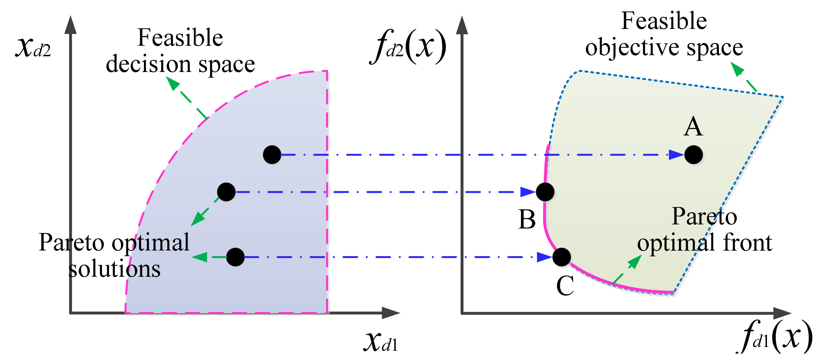
- Dias, A.H.F.; Vasconcelos, J.A. Multiobjective genetic algorithms applied to solve optimization problems. IEEE Trans. Magn. 2002, 38, 1133–1136. [Google Scholar] [CrossRef]
- Lei, G.; Wang, T.; Guo, Y.G.; Zhu, J.; Wang, S. System-level design optimization methods for electrical drive systems: Deterministic approach. IEEE Trans. Ind. Electron. 2014, 61, 6591–6602. [Google Scholar] [CrossRef]
- Diao, K.; Sun, X.; Lei, G.; Bramerdorfer, G.; Guo, Y.; Zhu, J. System-level robust design optimization of a switched reluctance motor drive system considering multiple driving cycles. IEEE Trans. Energy Convers. 2020, 36, 348–357. [Google Scholar] [CrossRef]
- Khan, M.A.; Husain, I.; Islam, R.; Klass, J. Design of experiments to address manufacturing tolerances and process variation influencing cogging torque and back EMF in the mass production of the permanent magnet synchronous motors. In Proceedings of the 2012 IEEE Energy Conversion Congress and Exposition, Raleigh, NC, USA, 15–20 September 2012; pp. 3032–3039. [Google Scholar]
- Xiao, S.; Li, Y.; Rotaru, M.; Sykulski, J.K. Six sigma quality approach to robust optimization. IEEE Trans. Magn. 2015, 51, 1–4. [Google Scholar] [CrossRef] [Green Version]
- Omekanda, A.M. Robust torque and torque-per-inertia optimization of a switched reluctance motor using the Taguchi methods. IEEE Trans. Ind. Appl. 2006, 42, 473–478. [Google Scholar] [CrossRef]
- Tang, Y.; Xiong, J.; Ma, D.; Zhang, X. Robust artificial noise aided transmit design for MISO wiretap channels with channel uncertainty. IEEE Commun. Lett. 2013, 17, 2096–2099. [Google Scholar] [CrossRef]
- Ma, B.; Lei, G.; Liu, C.; Zhu, J.; Guo, Y. Robust tolerance design optimization of a PM claw pole motor with soft magnetic composite cores. IEEE Trans. Magn. 2018, 54, 8102404. [Google Scholar] [CrossRef]
- Rafiee, V.; Faiz, J. Robust design of an outer rotor permanent magnet motor through six-sigma methodology using response surface surrogate model. IEEE Trans. Magn. 2019, 55, 8107110. [Google Scholar] [CrossRef]
- Duan, Y.; Ionel, D.M. A review of recent developments in electrical machine design optimization methods with a permanent-magnet synchronous motor benchmark study. IEEE Trans. Ind. Appl. 2013, 49, 1268–1275. [Google Scholar] [CrossRef]
- Putek, P.; Paplicki, P.; Pałka, R. Low cogging torque design of permanent magnet machine using modified multi-level set method with total variation regularization. IEEE Trans. Magn. 2014, 50, 657–660. [Google Scholar] [CrossRef]
- Asef, P.; Perpiñà, R.B.; Moazami, S.; Lapthorn, A.C. Rotor shape multi-level design optimization for double-stator permanent magnet synchronous motors. IEEE Trans. Energy Convers. 2019, 34, 1223–1231. [Google Scholar] [CrossRef]
- Asef, P.; Perpiñà, R.B.; Barzegaran, M.R. Multiobjective design optimization using dual-level response surface methodology and Booth’s algorithm for permanent magnet synchronous generators. IEEE Trans. Energy Convers. 2018, 33, 652–659. [Google Scholar] [CrossRef]
- Mo, L.; Zheng, G.; Zhang, T.; Lu, Q.; Liu, B. Multilevel optimization design for a flux-concentrating permanent-magnet brushless machine considering PM demagnetization limitation. IEEE Trans. Magn. 2021, 57, 1–5. [Google Scholar] [CrossRef]
- Lei, G.; Liu, C.; Zhu, J.; Guo, Y. Techniques for multilevel design optimization of permanent magnet motors. IEEE Trans. Energy Convers. 2015, 30, 1574–1584. [Google Scholar] [CrossRef]
- Lei, G.; Xu, W.; Hu, J.; Zhu, J.; Guo, Y.; Shao, K. Multilevel design optimization of a FSPMM drive system by using sequential subspace optimization method. IEEE Trans. Magn. 2014, 50, 685–688. [Google Scholar] [CrossRef]
- Sun, X.; Shi, Z.; Lei, G.; Guo, Y.; Zhu, J. Multi-objective design optimization of an IPMSM based on multilevel strategy. IEEE Trans. Ind. Electron. 2020, 68, 139–148. [Google Scholar] [CrossRef]
- Lei, G.; Liu, C.; Guo, Y.; Zhu, J. Multidisciplinary design analysis and optimization of a PM transverse flux machine with soft magnetic composite core. IEEE Trans. Magn. 2015, 51, 8109704. [Google Scholar] [CrossRef]
- Lei, G.; Bramerdorfer, G.; Ma, B.; Guo, Y.; Zhu, J. Robust design optimization of electrical machines: Multi-objective approach. IEEE Trans. Energy Convers. 2020, 36, 390–401. [Google Scholar] [CrossRef]
- Lebensztajn, L.; Marretto, C.A.R.; Costa, M.C.; Coulomb, J.-L. Kriging: A useful tool for electromagnetic device optimization. IEEE Trans. Magn. 2004, 40, 1196–1199. [Google Scholar] [CrossRef]


Publisher’s Note: MDPI stays neutral with regard to jurisdictional claims in published maps and institutional affiliations. |
© 2022 by the authors. Licensee MDPI, Basel, Switzerland. This article is an open access article distributed under the terms and conditions of the Creative Commons Attribution (CC BY) license (https://creativecommons.org/licenses/by/4.0/).
Share and Cite
Liu, L.; Guo, Y.; Yin, W.; Lei, G.; Zhu, J. Design and Optimization Technologies of Permanent Magnet Machines and Drive Systems Based on Digital Twin Model. Energies 2022, 15, 6186. https://doi.org/10.3390/en15176186
Liu L, Guo Y, Yin W, Lei G, Zhu J. Design and Optimization Technologies of Permanent Magnet Machines and Drive Systems Based on Digital Twin Model. Energies. 2022; 15(17):6186. https://doi.org/10.3390/en15176186
Chicago/Turabian StyleLiu, Lin, Youguang Guo, Wenliang Yin, Gang Lei, and Jianguo Zhu. 2022. "Design and Optimization Technologies of Permanent Magnet Machines and Drive Systems Based on Digital Twin Model" Energies 15, no. 17: 6186. https://doi.org/10.3390/en15176186
APA StyleLiu, L., Guo, Y., Yin, W., Lei, G., & Zhu, J. (2022). Design and Optimization Technologies of Permanent Magnet Machines and Drive Systems Based on Digital Twin Model. Energies, 15(17), 6186. https://doi.org/10.3390/en15176186