
Mathematical Model Derivation and Experimental Verification of Novel Consequent-Pole Adjustable Speed PM Motor †

Abstract
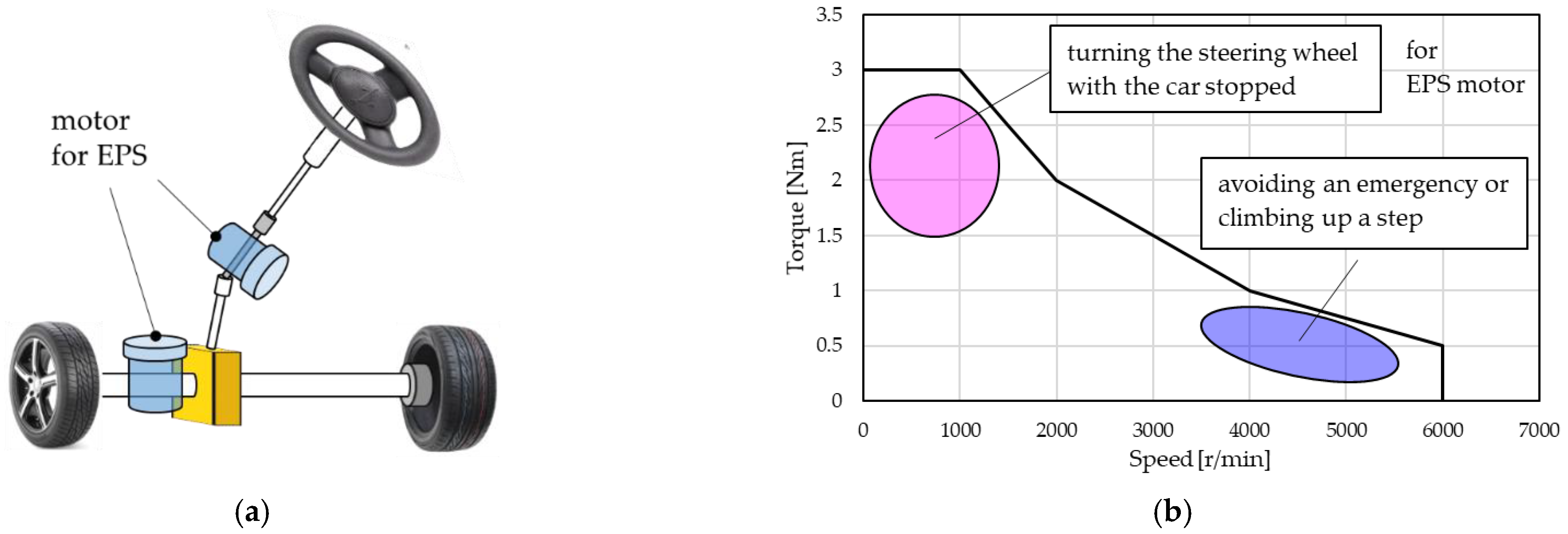
:1. Introduction
2. Overview of Novel Consequent-Pole PM Motor
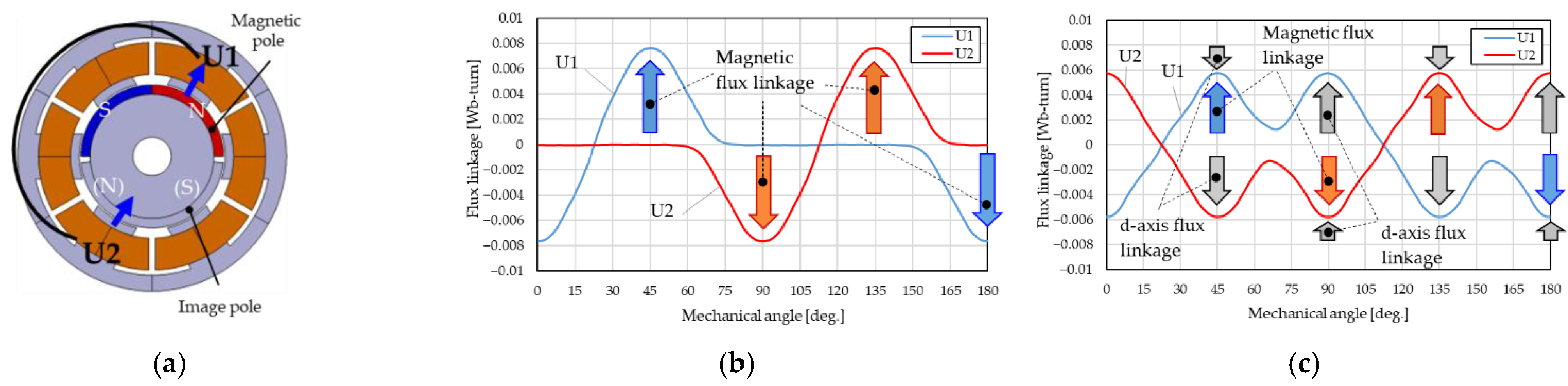
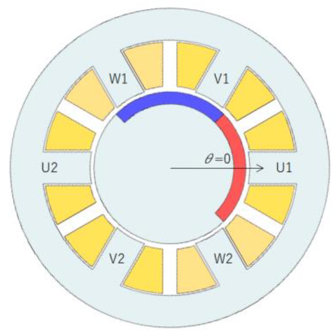
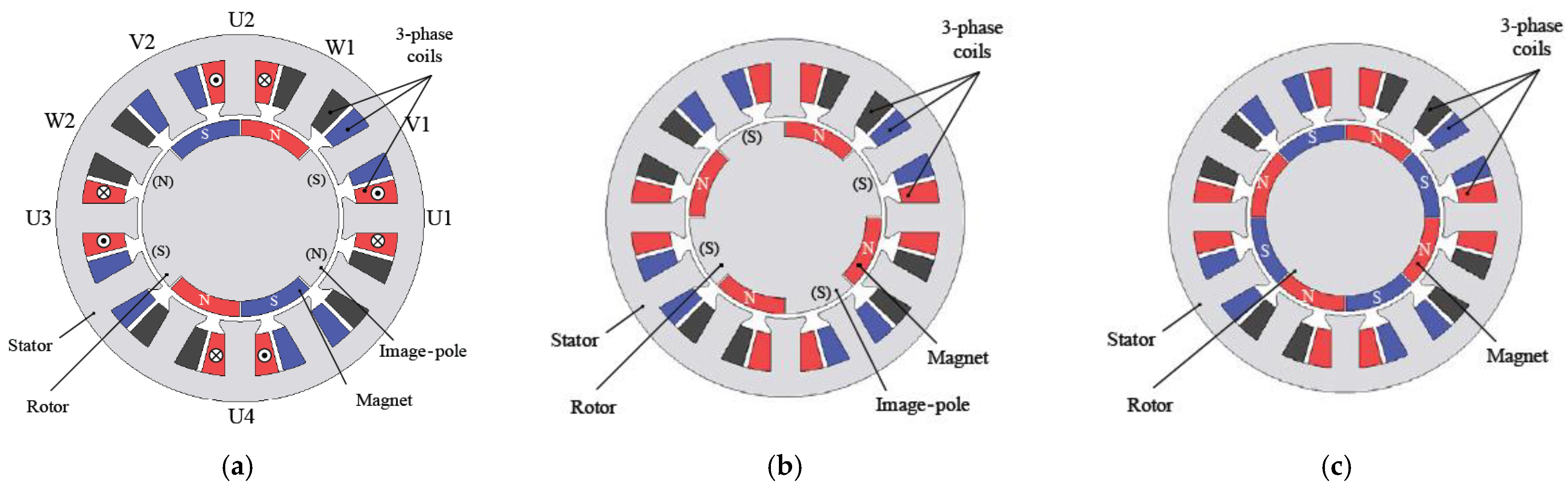
2.1. Motor Structure and Driving Principle
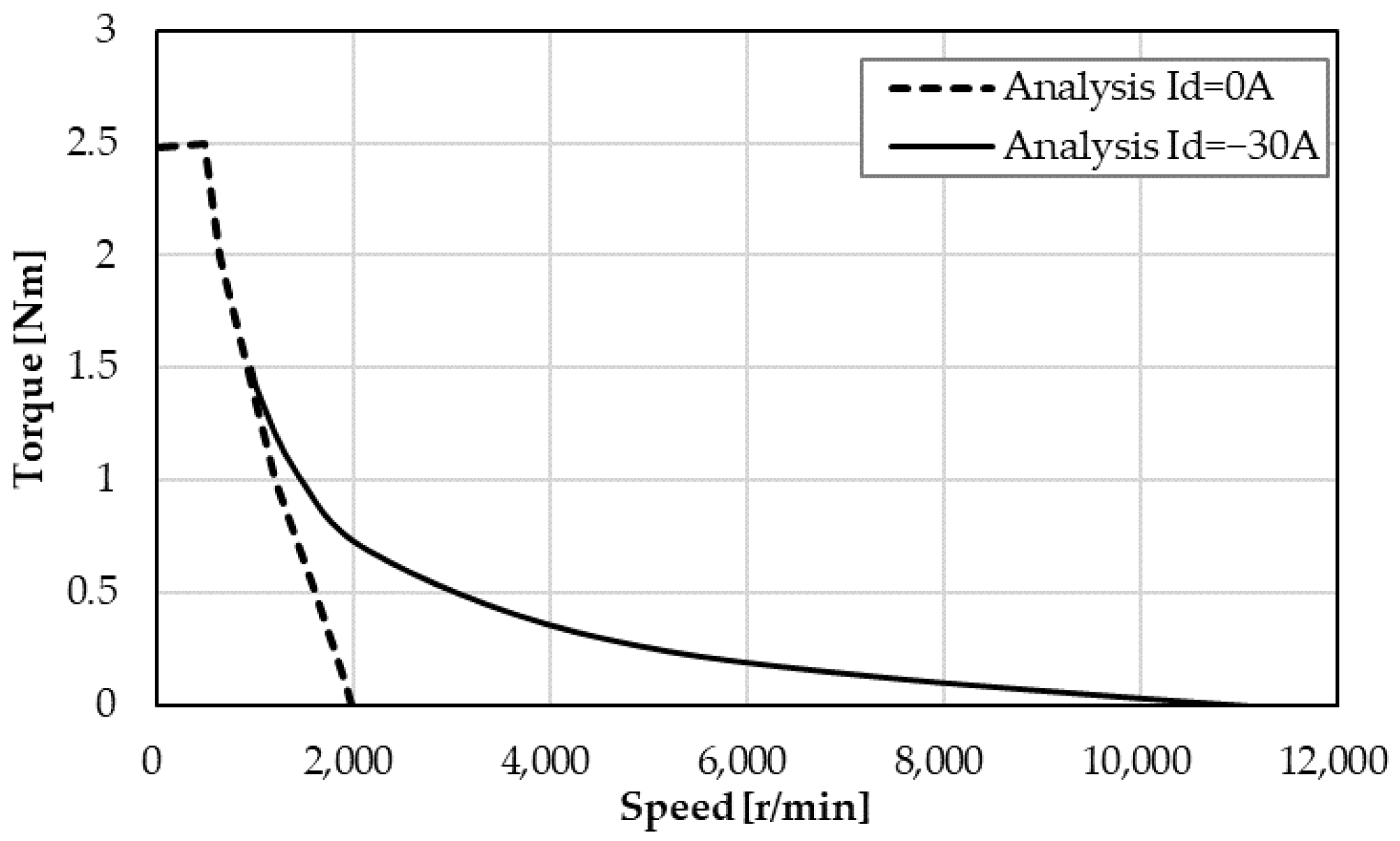
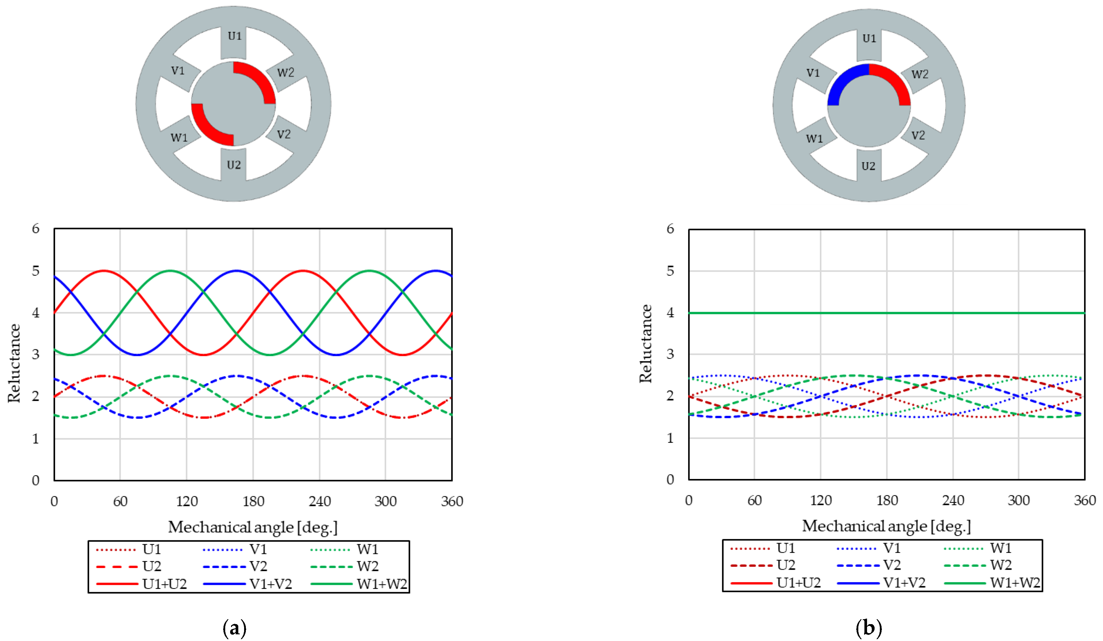
2.2. Effect of Adjustable Speed
2.3. Mathematical Model Derivation
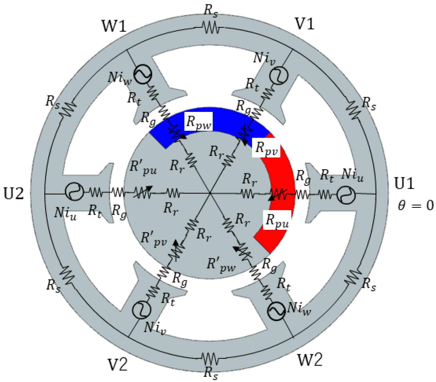
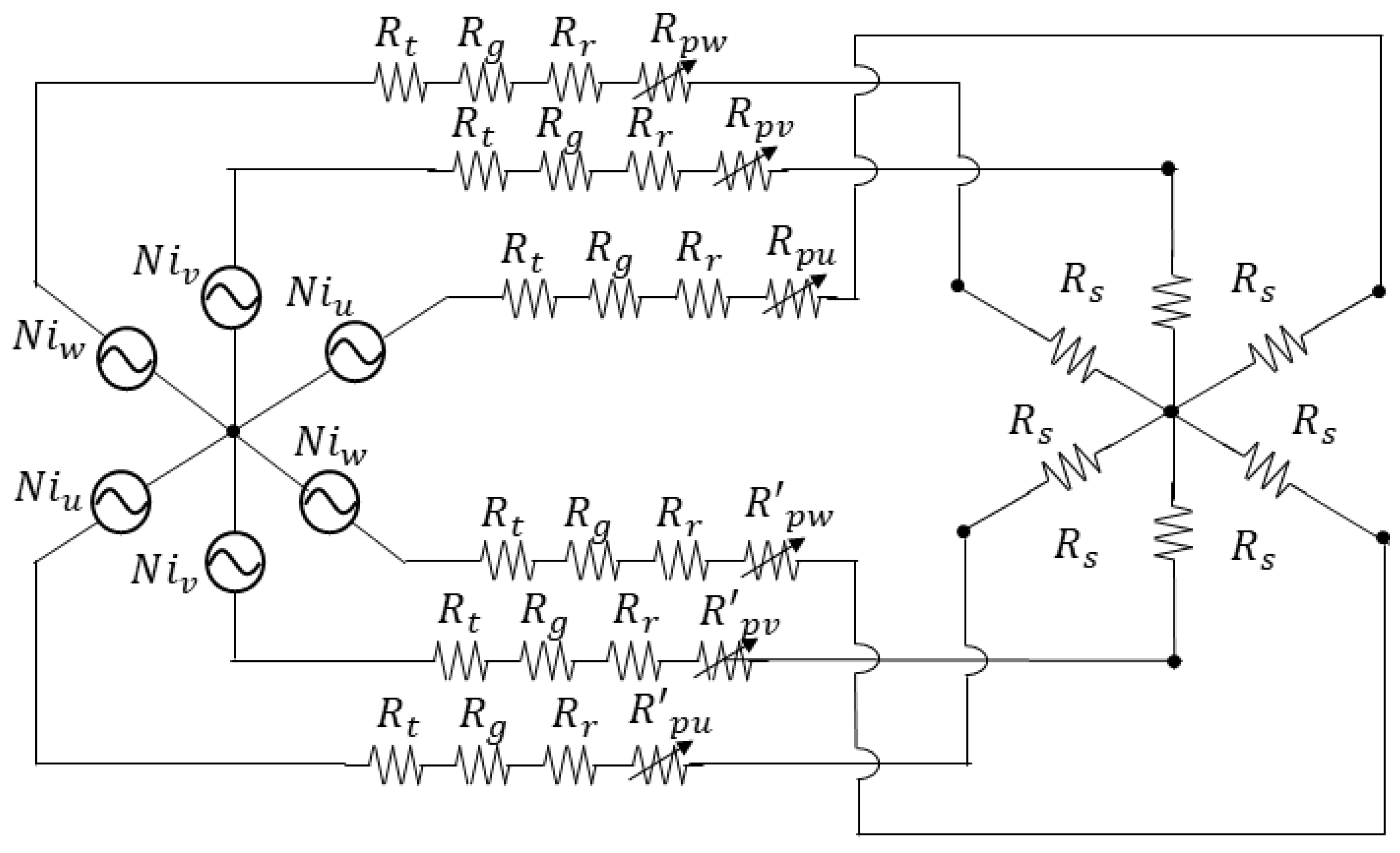
2.3.1. Magnetic Circuit of the Novel Consequent-Pole PM Motor
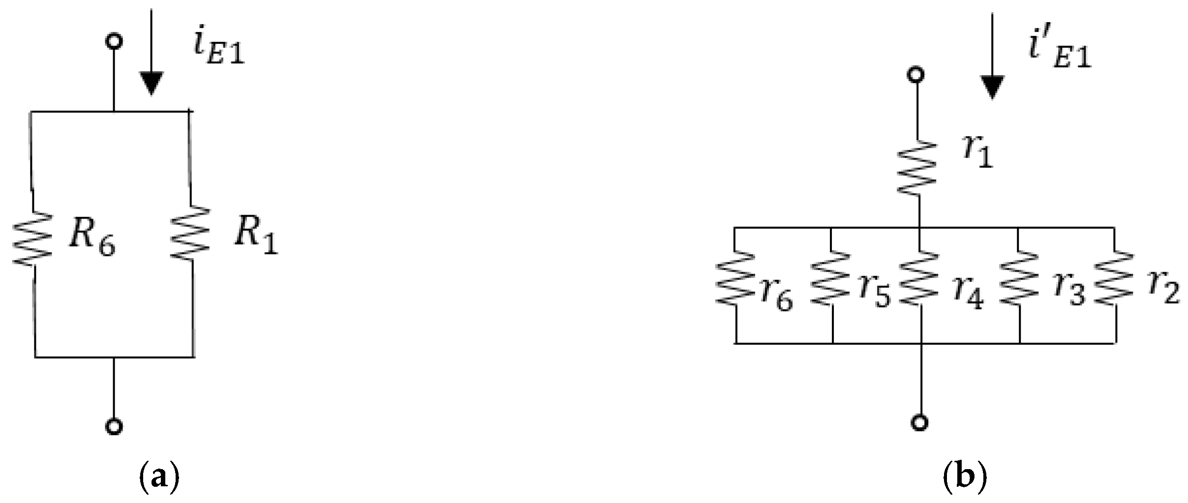
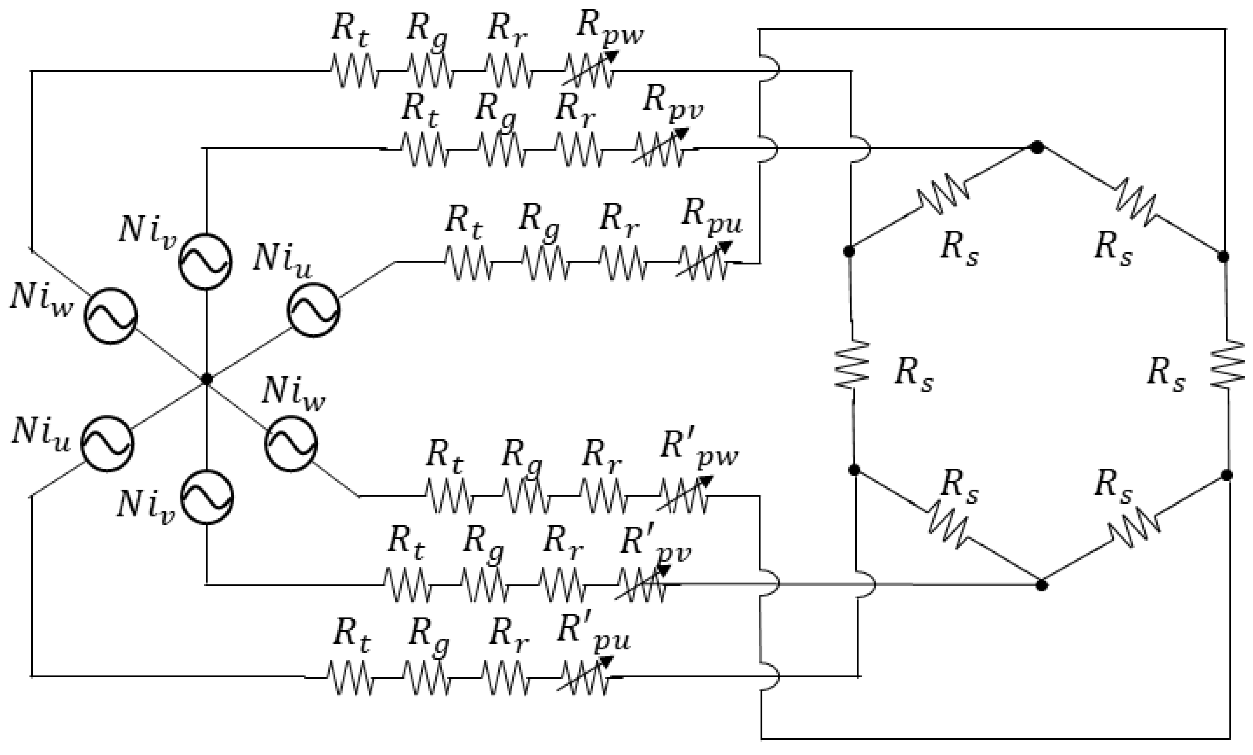
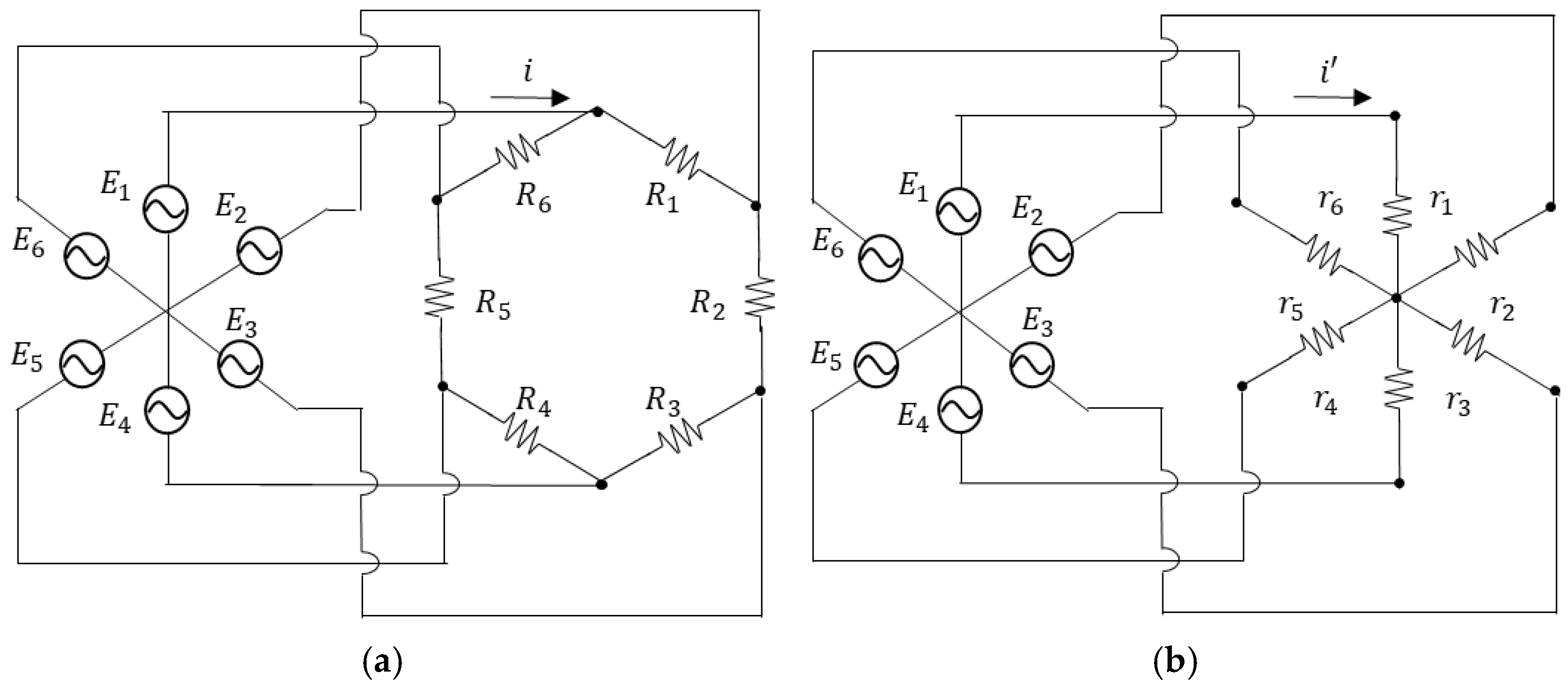
2.3.2. Six-Phase Hexagon-Star Transformation
2.3.3. Derivation of the Theoretical Equation for the Armature Flux
2.3.4. Derivation of the Voltage Equation of the Novel Consequent-Pole PM Motor
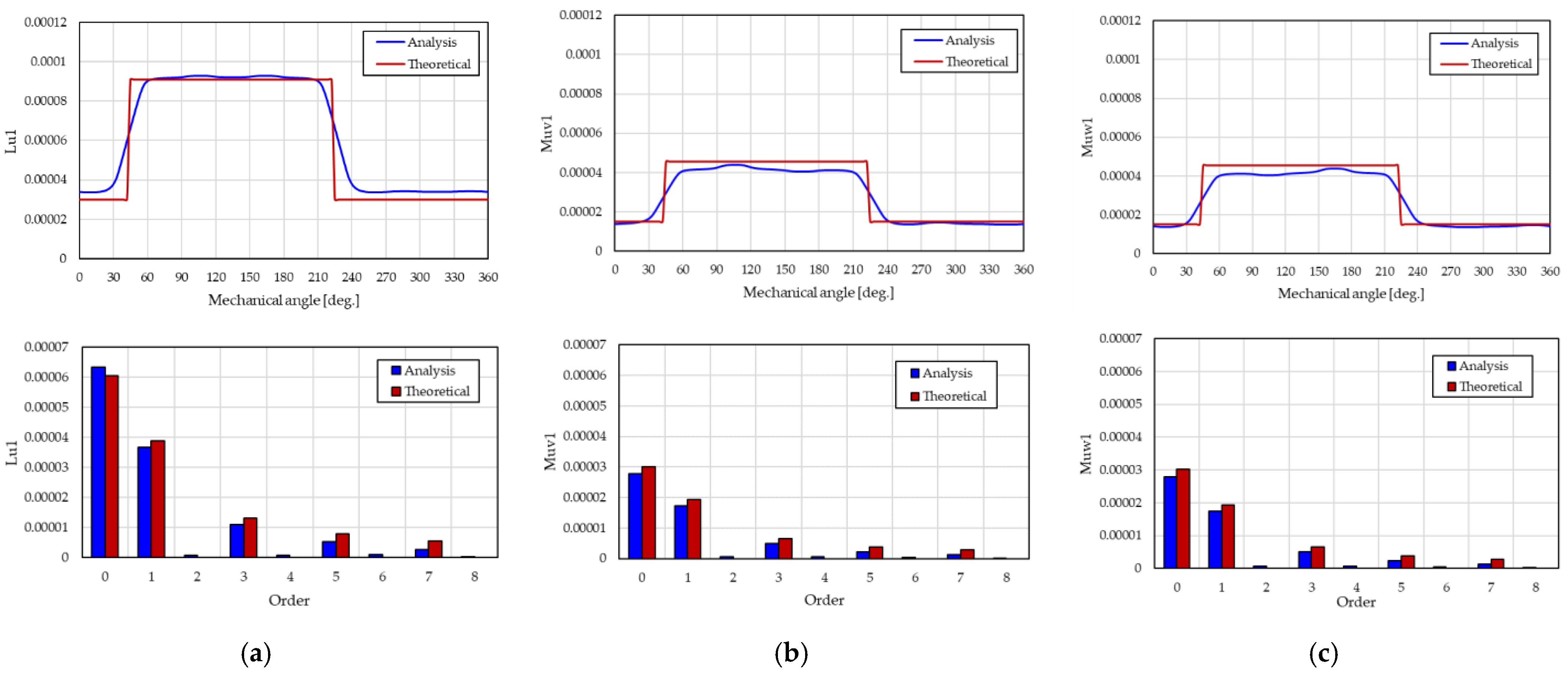
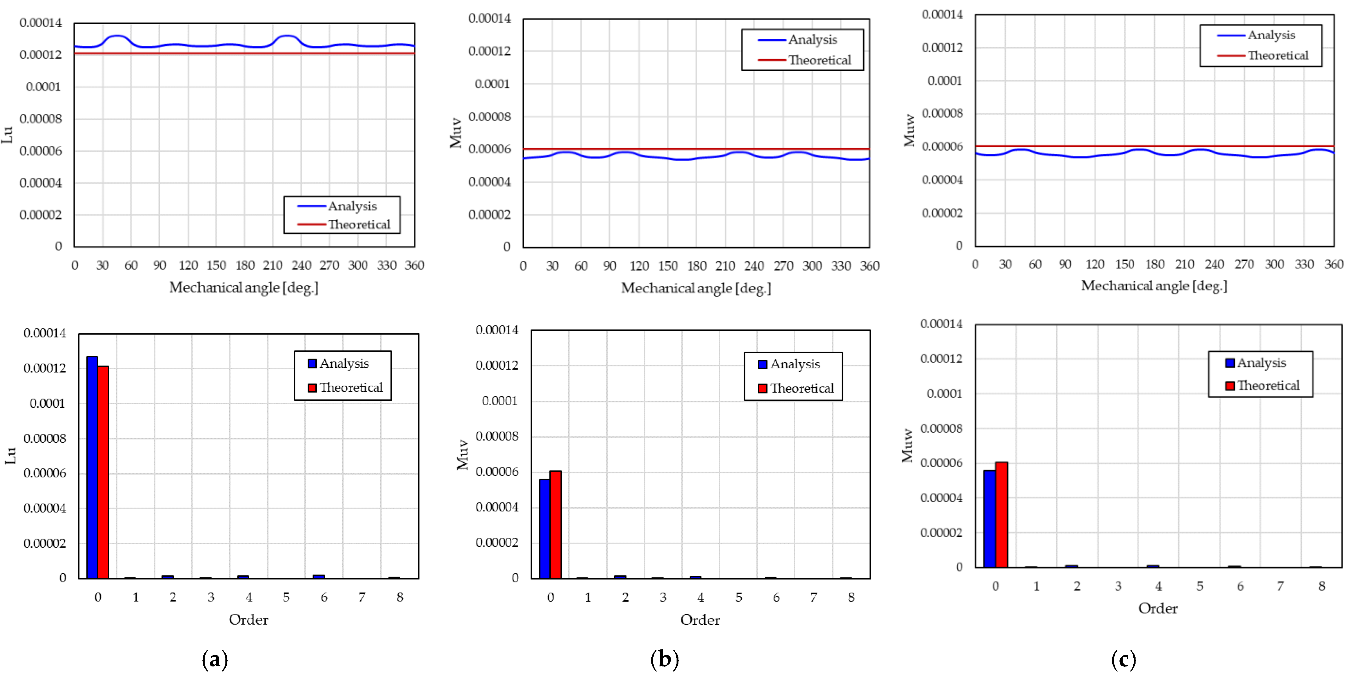
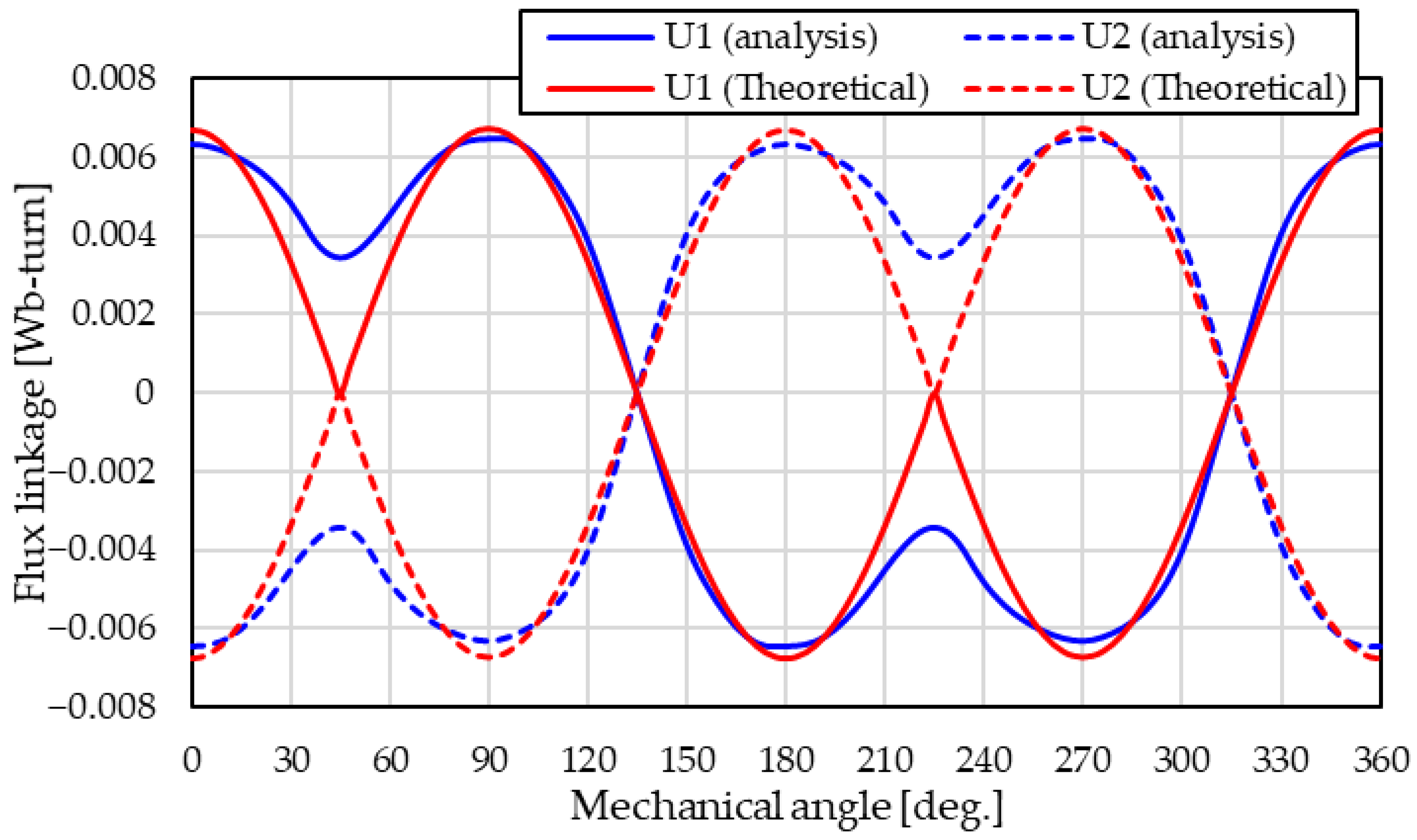
2.3.5. Mathematical Model Validation by Analysis
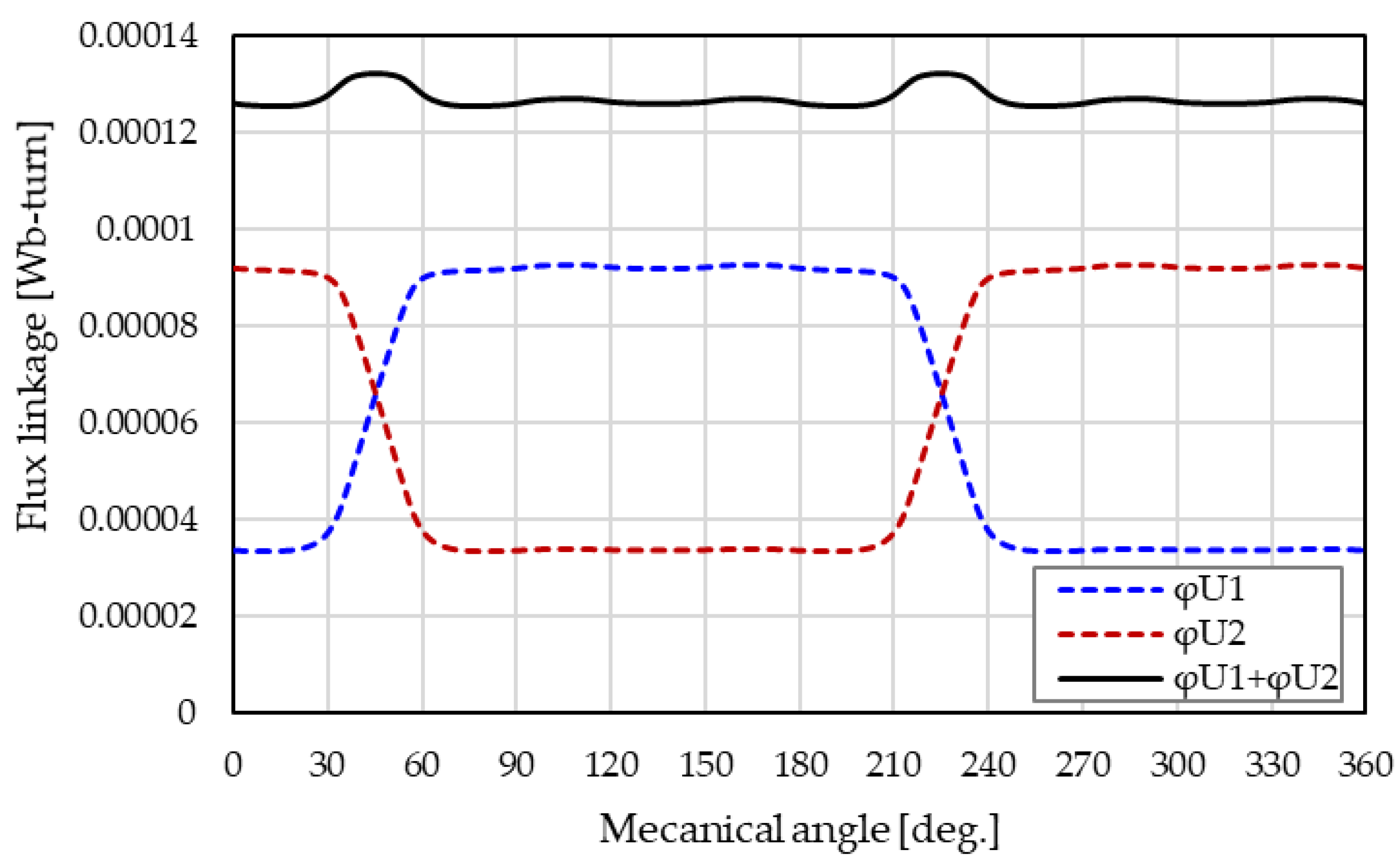
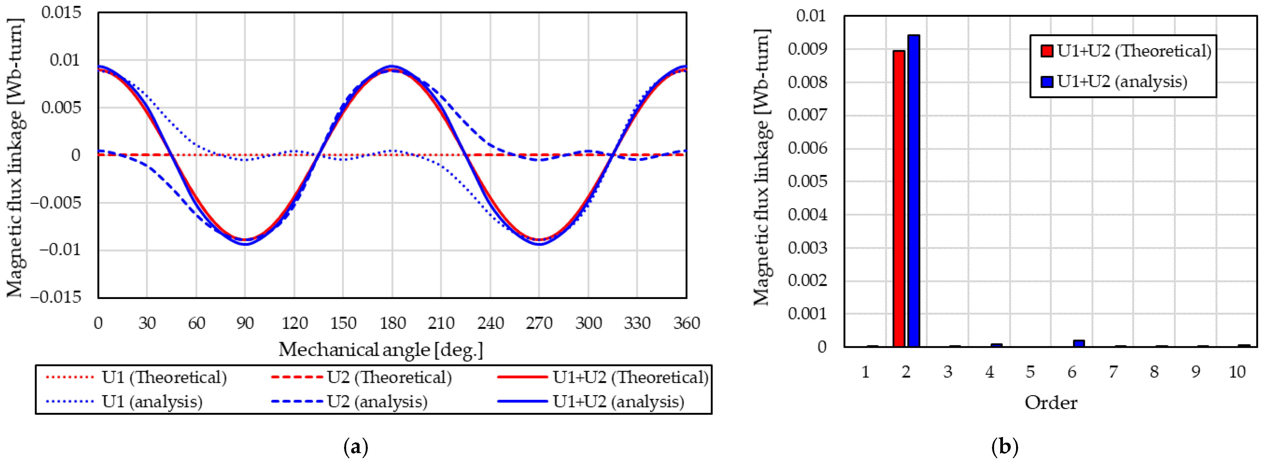
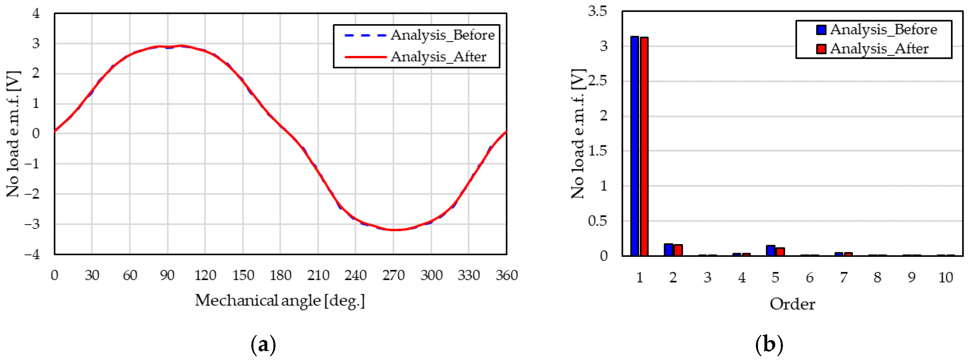
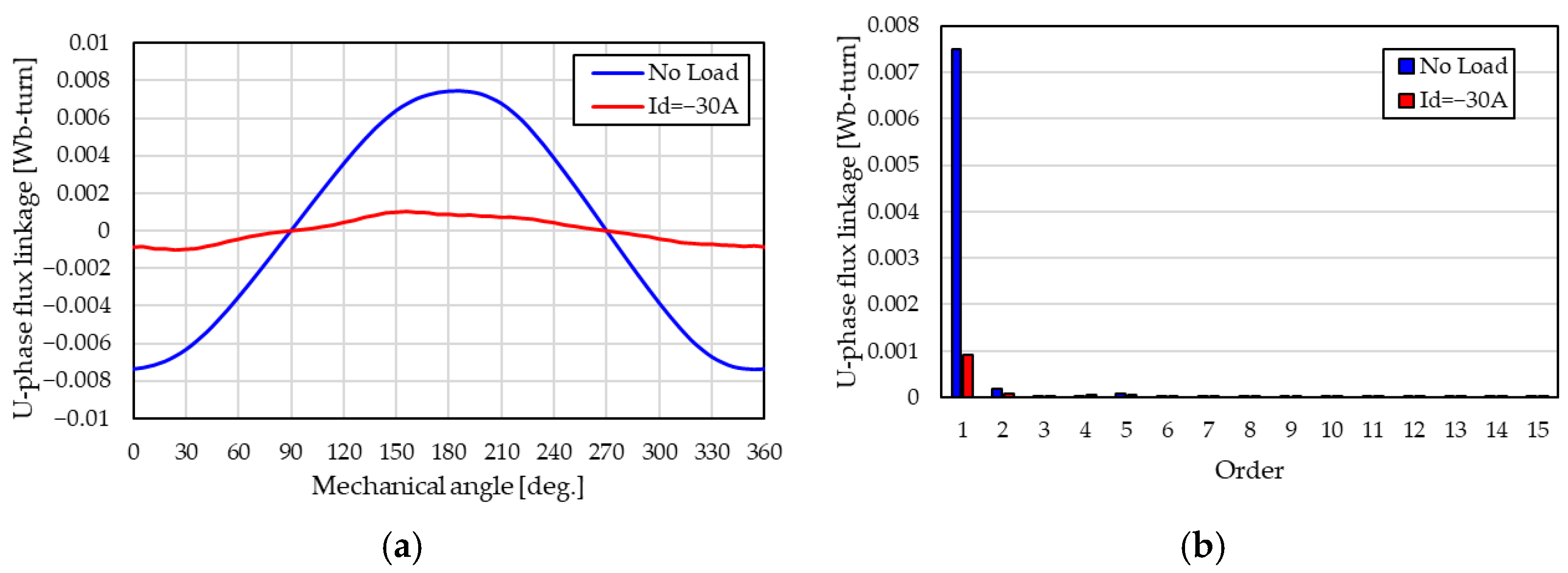
2.3.6. Induced Voltage Cancellation Verification by Analysis
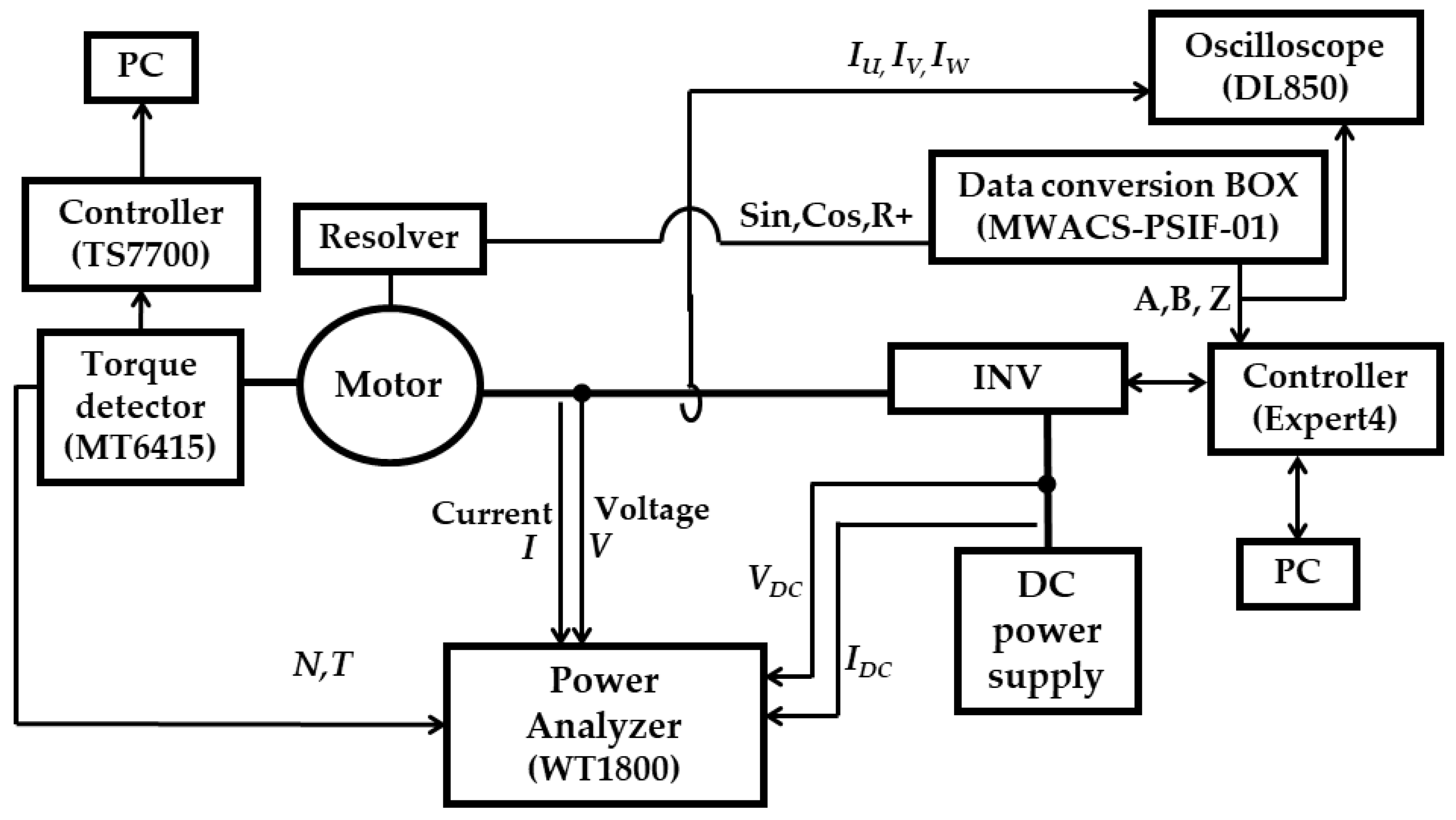
3. Mathematical Model Validation by Prototype Motor Drive
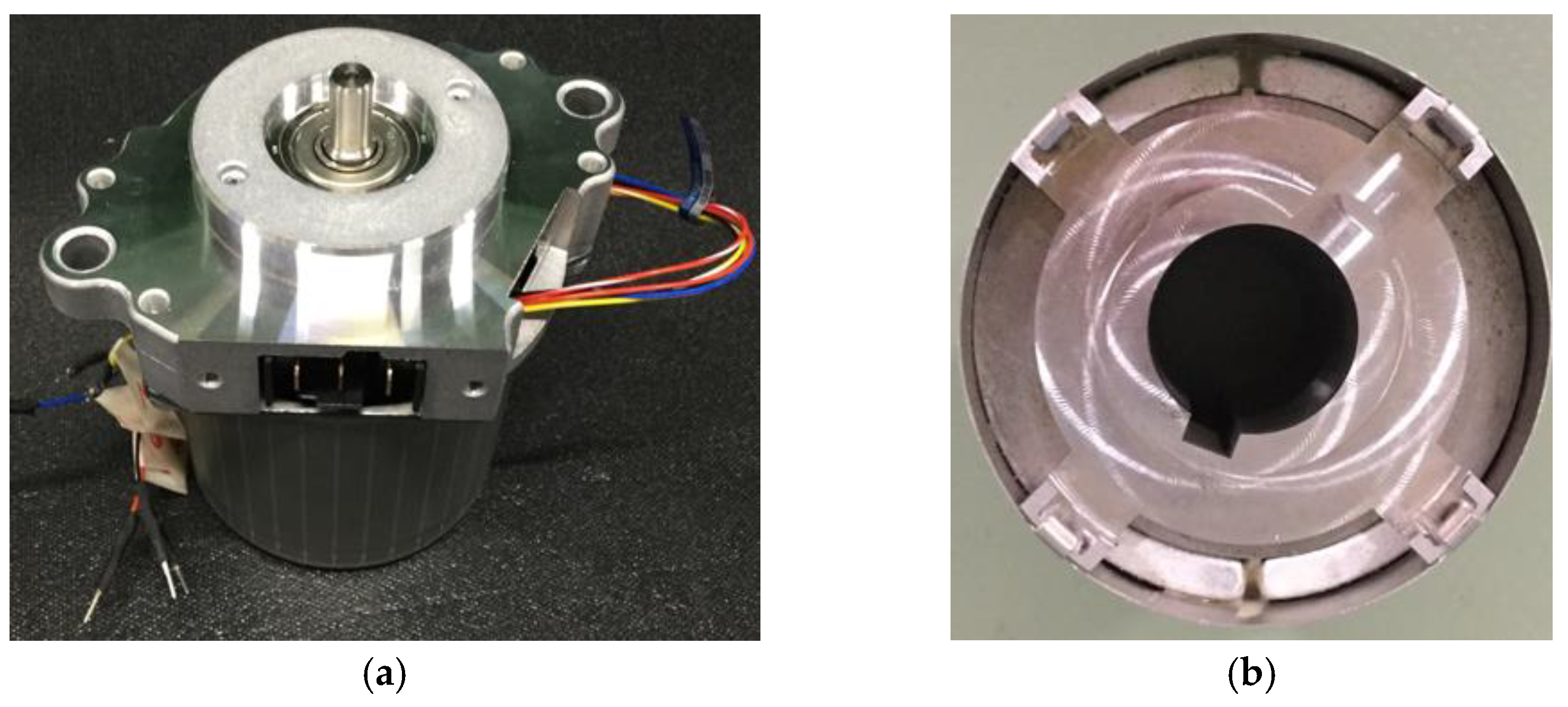
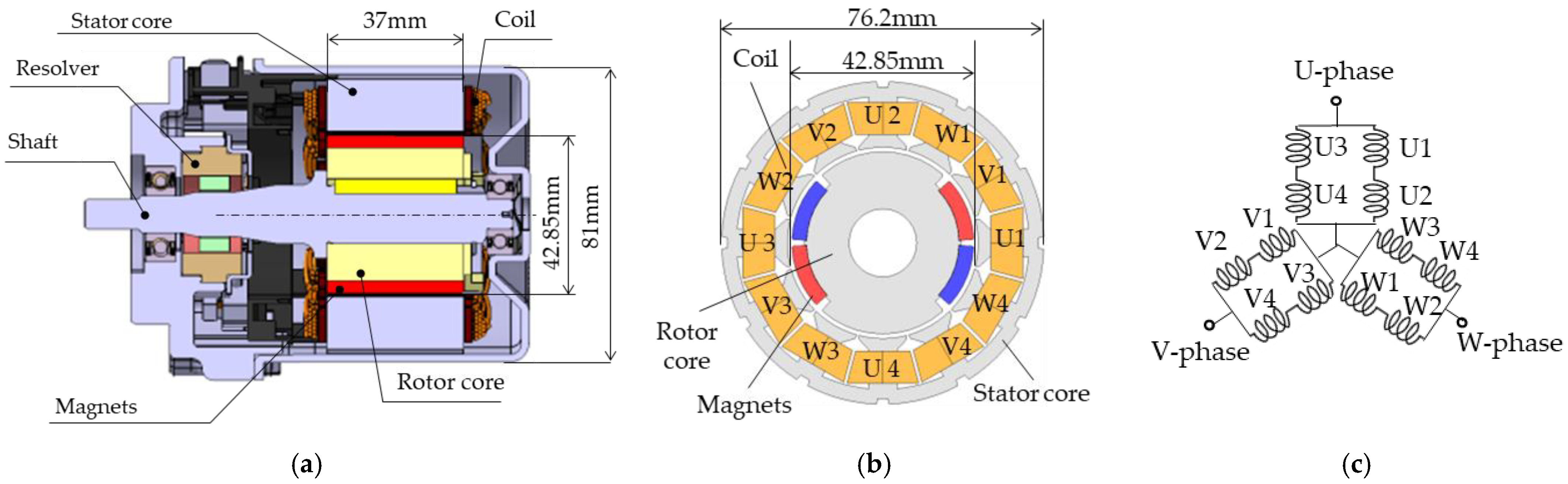
3.1. Prototype Motor
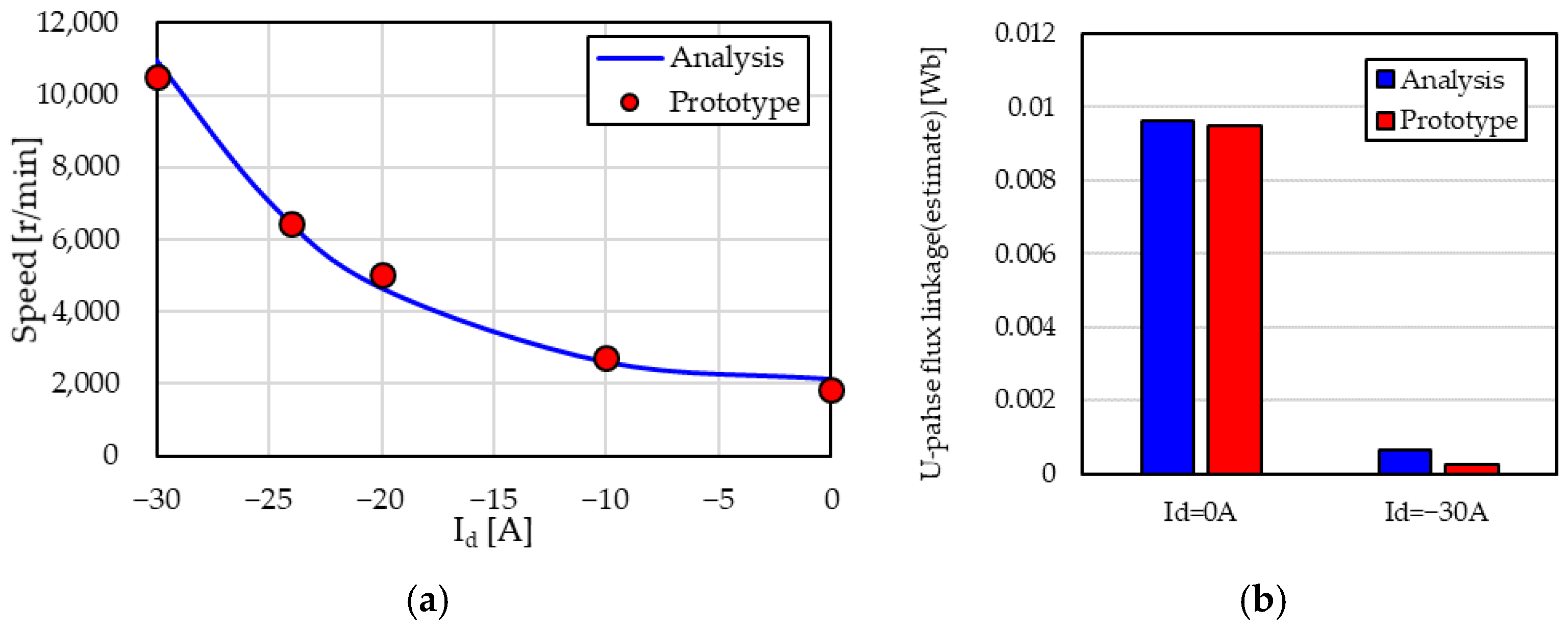
3.2. Validation of Effect of Adjustable Speed by Prototype Motor
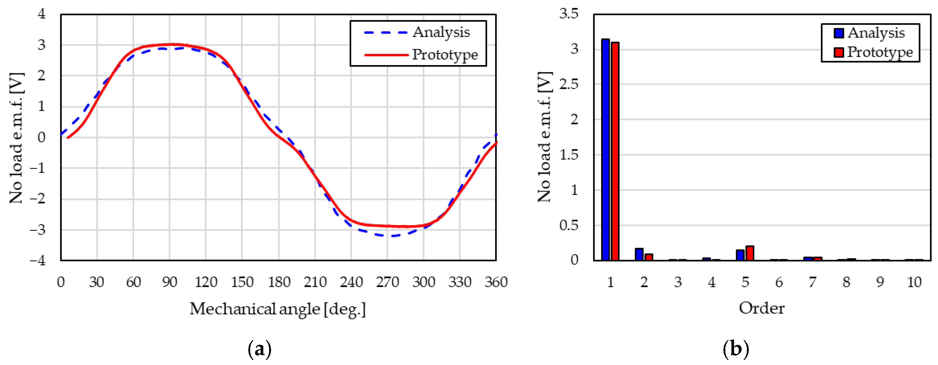
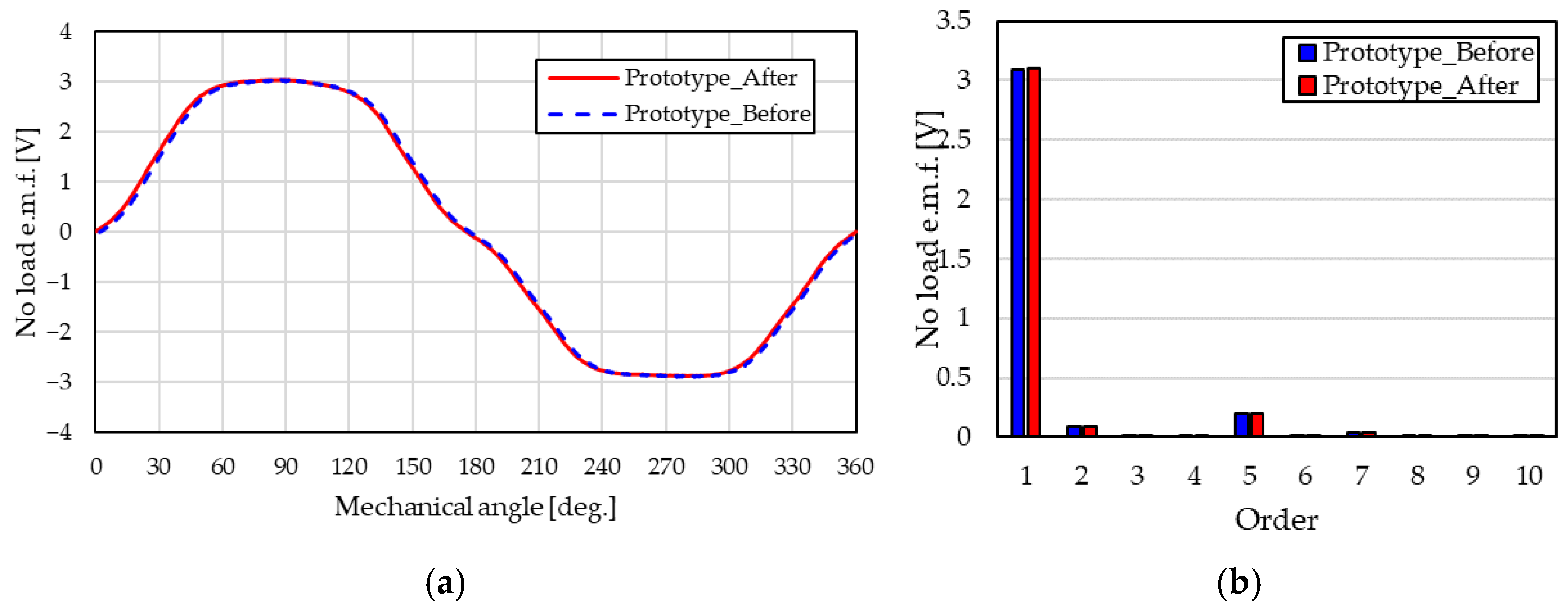
3.3. Back e.m.f. Characteristics
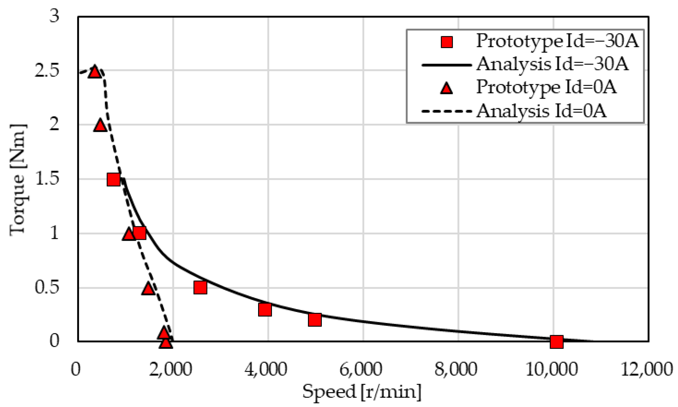
3.4. N-T Characteristics
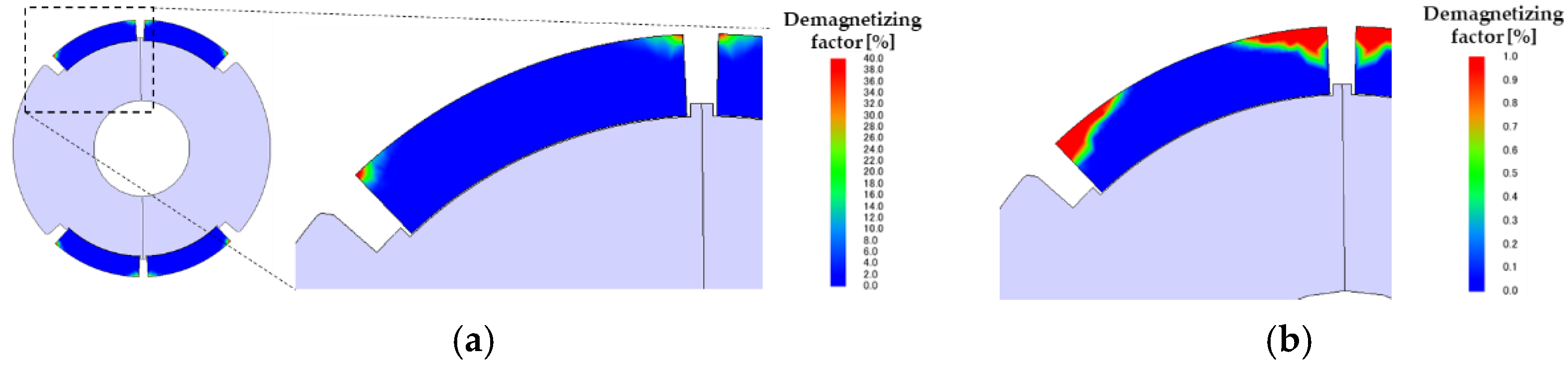
3.5. Demagnetizing Characteristics
4. Comparison of Characteristics of Novel Consequent-Pole PM Motor
4.1. Motor Specifications
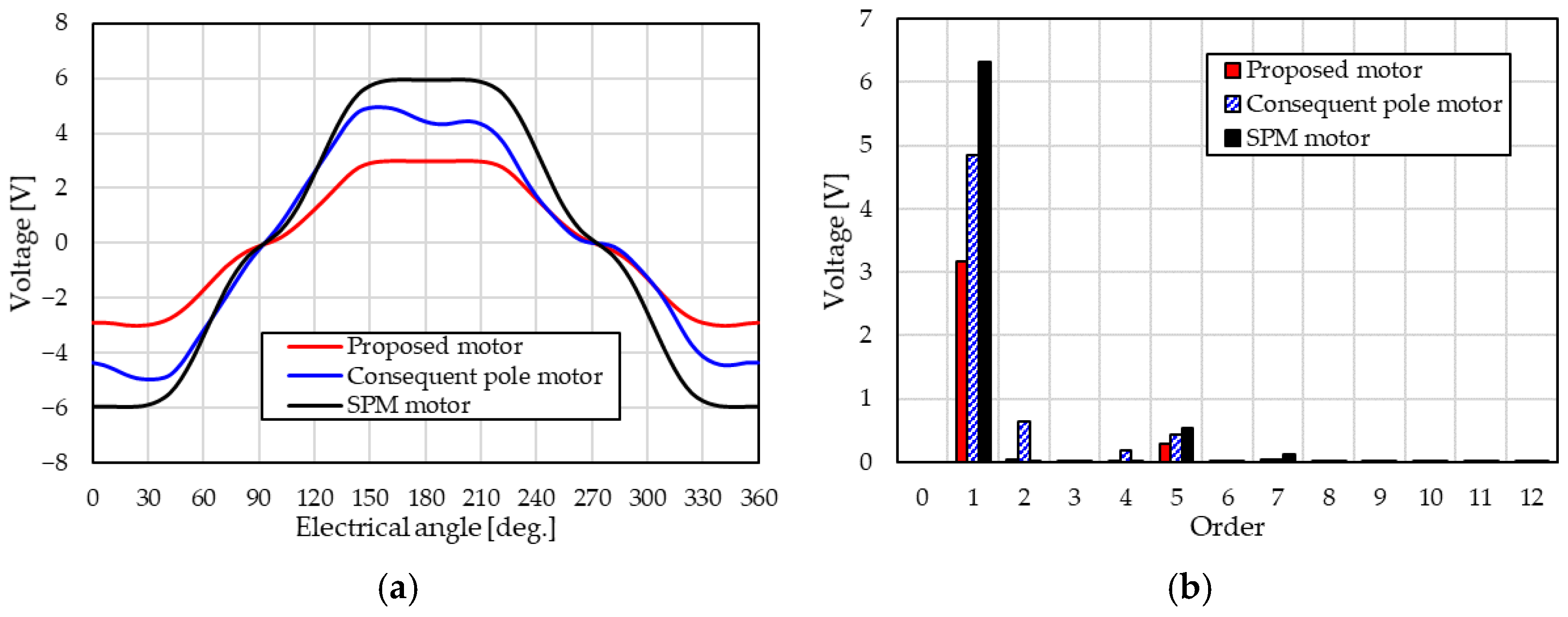
4.2. Comparison of No-Load Electromotive Force
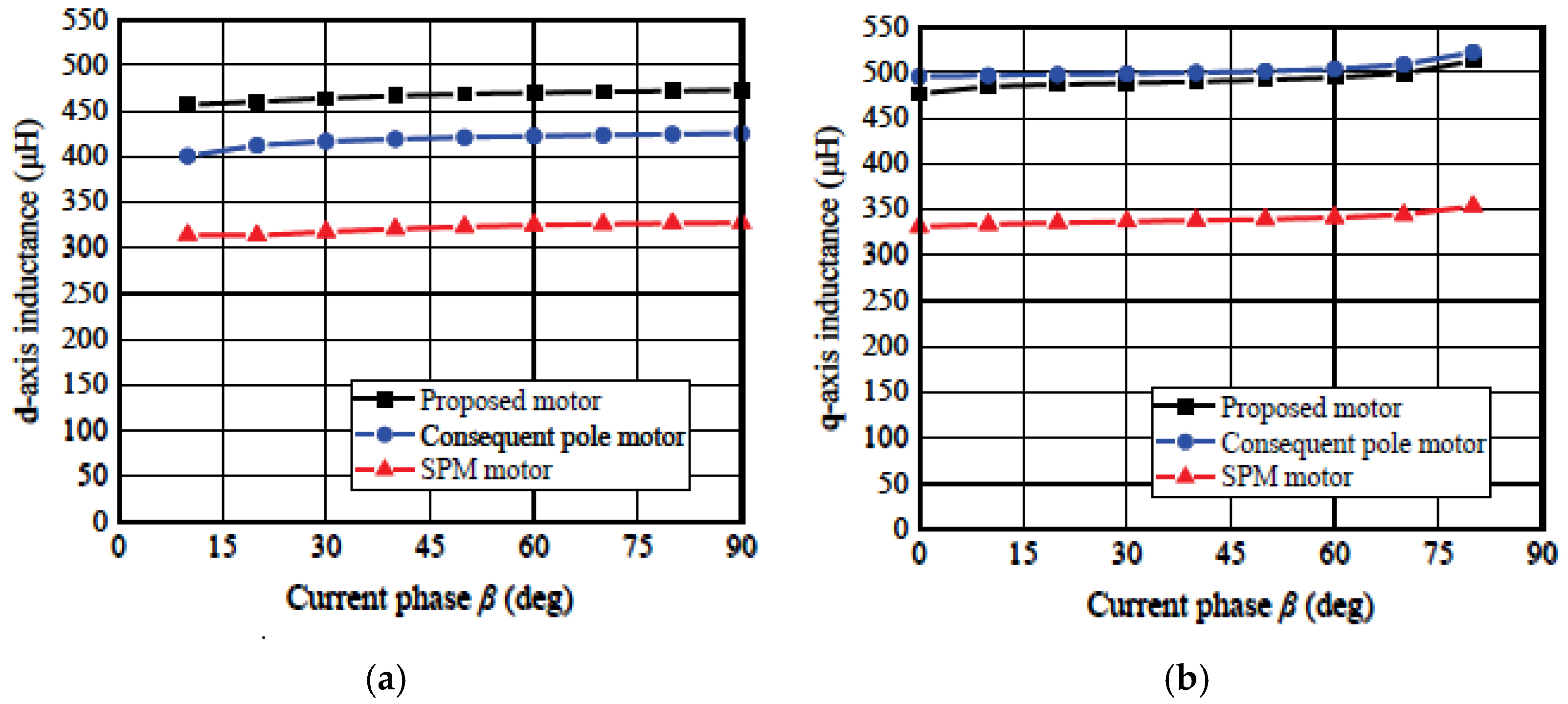
4.3. Comparison of Inductance
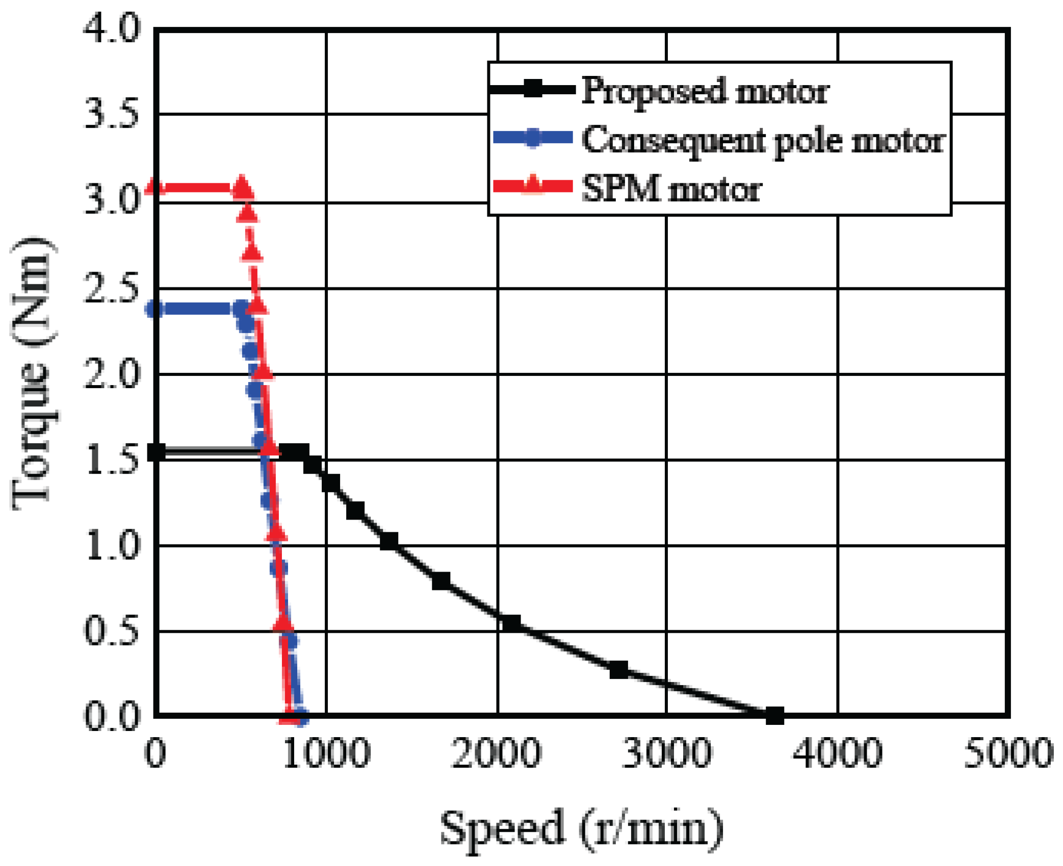
4.4. Comparison of N-T Characteristics
5. Conclusions
- The derived voltage equation is equivalent to that of the general SPM type.
- The derived voltage equation was shown to be valid, with the same trend as the analytical results.
- The control theory for the motor drive based on the derived mathematical model worked on the prototype motor and was shown to be valid by measurement.
- The proposed motor can vary the fundamental component of the number of the flux linkage in the range of 3–100% by field weakening in the experiment.
- The demagnetization resistance of the proposed motor was high. There was virtually no significant degradation of motor characteristics due to irreversible demagnetization in analysis and measurement.
- Analysis clarified that the harmonic component of the proposed motor was less than that of the conventional consequent-pole type.
- The proposed motor has the most extensive high-speed operation range with the least negative d-axis current; thus, the field weakening operation can be achieved efficiently through the three motors.
Author Contributions
Funding
Institutional Review Board Statement
Informed Consent Statement
Data Availability Statement
Conflicts of Interest
References
- Kato, T.; Minowa, M.; Hijikata, H.; Akatsu, K.; Lorenz, D.R. Design Methodology for Variable Leakage Flux IPM for Automobile Traction Drives. IEEE Trans. Ind. Appl. 2015, 51, 3811–3821. [Google Scholar] [CrossRef]
- Wang, J.; Yuan, X.; Atallah, K. Design Optimization of a Surface-Mounted Permanent Magnet Motor with Concentrated Windings for Electric Vehicle Applications. IEEE Trans. Veh. Technol. 2013, 62, 1053–1064. [Google Scholar] [CrossRef]
- Kuwahara, Y.; Kosaka, T.; Kamada, Y.; Kajiura, H.; Matsui, N. Experimental Verification of High-Power Production Mechanism by Increasing Field Winding Current in Wound Field Flux Switching Motor for HEV Traction Drive. IEEJ Trans. Ind. Appl. 2015, 135, 939–947. [Google Scholar] [CrossRef]
- Kato, T.; Limsuwan, N.; Yu, C.; Akatsu, K.; Lorenz, D.R. Rare Earth Reduction Using a Novel Variable Magnetomotive Force Flux-Intensified IPM Machine. IEEE Trans. Ind. Appl. 2014, 50, 1748–1756. [Google Scholar] [CrossRef]
- Motoki, K.; Fukami, T.; Koyama, M.; Mori, T.; Yamada, M.; Nakano, M. Driving Characteristics of an Electromagnet-Assisted Magnet Motor. IEEJ Trans. Ind. Appl. 2018, 138, 546–552. [Google Scholar] [CrossRef]
- Namba, M.; Hiramoto, K.; Nakai, H. Novel Variable-Field Motor with a Three-Dimensional Magnetic Circuit. IEEJ Trans. Ind. Appl. 2015, 135, 1085–1090. [Google Scholar] [CrossRef]
- Kalluf, H.J.F.; Tutelea, L.; Boldea, I.; Espindola, A. 2/4-Pole Split-Phase Capacitor Motor for Small Compressors: A Comprehensive Motor Characterization. IEEE Trans. Ind. Appl. 2014, 50, 356–363. [Google Scholar] [CrossRef]
- Tanaka, A.; Nakada, T.; Hoshika, S.; Takahashi, N.; Koike, Y.; Yamazaki, K. Development of traction motor for 100% electric drive hybrid vehicle. In Proceedings of the IEEJ Industrial Applications Society Conference, Nagaoka, Japan, 25–27 August 2021; pp. 245–248. [Google Scholar]
- Shimizu, R.; Sakai, K. Basic Study on Variable Flux Hybrid Reluctance Motor for Electric Vehicles. In Proceedings of the IEEJ Annual Meeting, Okayama, Japan, 21–23 March 2022; pp. 104–105. [Google Scholar]
- Iwama, K.; Noguchi, T. Operation Characteristics of Adjustable Field IPMSM Utilizing Magnetic Saturation. Energies 2022, 15, 52. [Google Scholar] [CrossRef]
- Lee, D.; Ro, J. Analysis and Design of a High-Performance Traction Motor for Heavy-Duty Vehicles. Energies 2020, 13, 3150. [Google Scholar] [CrossRef]
- Yamazaki, N.; Ogata, S.; Ishikawa, T. Analysis of Slotless PM Synchronous Motor for EPS. In Proceedings of the IEEJ Annual Meeting, Oosaka, Japan, 9–11 March 2021; p. 48. [Google Scholar]
- Swamy, M.; Kume, J.T.; Maemura, A.; Morimoto, S. Extended High Speed Operation via Electronic Winding Change Method for AC Motors. IEEE Trans. Ind. Appl. 2006, 42, 742–752. [Google Scholar] [CrossRef]
- Kume, T.; Iwakane, T.; Sawa, T.; Yoshida, T.; Nagai, I. A Wide Constant Power Range Vector Controlled AC Motor Drive Using Winding Changeover Technique. IEEE Trans. Ind. Appl. 2006, 27, 934–939. [Google Scholar] [CrossRef]
- Ostovi, V. Pole Pole-Changing Permanent Permanent-Magnet Machines. IEEE Trans. Ind. Appl. 2002, 38, 1493–1499. [Google Scholar] [CrossRef]
- Sridharbabu, M.; Kosaka, T.; Matsui, N. Design Reconsiderations of High Speed Permanent Magnet Hybrid Excitation Motor for Main Spindle Drive in Machine Tools Based on Experimental Results of Prototype Machine. IEEE Trans. Magn. 2011, 47, 4469–4472. [Google Scholar] [CrossRef]
- Song, C.; Song, I.; Shin, H.; Lee, C.; Kim, K. A Design of IPMSM for High-Power Electric Vehicles With Wide-Field-Weakening Control Region. IEEE Trans. Magn. 2022, 58, 8700305. [Google Scholar] [CrossRef]
- Ngo, D.; Hsieh, M.; Le, T. Analysis on Field Weakening of Flux Intensifying Synchronous Motor Considering PM Dimension and Armature Current. IEEE Trans. Magn. 2022, 57, 8202305. [Google Scholar] [CrossRef]
- Isam, M.; Mikail, R.; Husain, I. Field Weakening Operation of Slotless Permanent Magnet Machines Using Stator Embedded Inductor. IEEE Trans. Ind. Appl. 2021, 57, 2387–2397. [Google Scholar] [CrossRef]
- Morimoto, S.; Takeda, Y.; Hirasa, T.; Taniguchi, K. Expansion of Operating Limits for Permanent Magnet Motor by Current Vector Control Considering Inverter Capacity. IEEE Trans. Ind. Appl. 1990, 5, 866–871. [Google Scholar] [CrossRef]
- Morimoto, S.; Hatanaka, K.; Tong, Y.; Takeda, Y.; Hirasa, T. Variable Speed Drive System of Permanent Magnet Synchronous Motors with Flux-weakening Control. IEEJ Trans. Ind. Appl. 1992, 112, 292–298. [Google Scholar] [CrossRef]
- Jahns, M.T. Flux-weakening Regime Operation of an Interior Permanent magnet Synchronous Motor Drive. IEEE Trans. Ind. Appl. 1987, 4, 681–689. [Google Scholar] [CrossRef]
- Donald, E.B.; Novotny, W.D.; Lipo, A.T. Field weakening in Buried Permanent magnet AC Motor Drive. IEEE Trans. Ind. Appl. 1987, 2, 398–407. [Google Scholar]
- Morimoto, S.; Sanada, M.; Takeda, Y.; Takeda, Y. Wide Speed Operation of Interior Permanent Magnet Synchronous Motors with High Performance Current Regulator. IEEE Trans. Ind. Appl. 1994, 4, 920–926. [Google Scholar] [CrossRef]
- Noguchi, T.; Murakami, K.; Hattori, A.; Kaneko, Y. Torque Boost Operation of New Consequent-Pole Permanent Magnet Motor Using Zero-Phase Circuit. In Proceedings of the 2019 IEEE 12th International Conference on Electrical Machines and Systems (ICEMS), Harbin, China, 11–14 August 2019. [Google Scholar]
- Murakami, K.; Noguchi, T.; Hattori, A.; Kaneko, Y. Investigation on Torque Boost Operation of Novel Consequent-Pole Motor Using Zero-Phase Circuit. In Proceedings of the IEEJ Technical Meeting on Semiconductor Power Converter and Motor Drive, Iwate, Japan, 12–13 September 2019; pp. 91–96. [Google Scholar]
- Wu, Z.; Fan, Y.; Chen, H.; Wang, X.; Lee, T.C. Electromagnetic Force and Vibration Study of Dual-Stator Consequent-Pole Hybrid Excitation Motor for Electric Vehicles. IEEE Trans. Veh. Technol. 2021, 70, 8700205. [Google Scholar] [CrossRef]
- Jiang, J.; Niu, S.; Zhao, X.; Fu, N.W. A Novel Winding Switching Control Strategy of a Consequent-Pole Ferrite-PM Hybrid-Excited Machine for Electric Vehicle Application. IEEE Trans. Magn. 2022, 58, 742–752. [Google Scholar] [CrossRef]
- Nara, G.; Shiomura, S. Torque Ripple Reduction Method by Injecting Harmonic Current in PMSM. In Proceedings of the IEEJ Industrial Applications Society Conference, Nagaoka, Japan, 25–27 August 2021; pp. 371–372. [Google Scholar]
- Zhang, Z.; Zhang, M.; Yin, J.; Wu, J.; Yang, C. An Analytical Method for Calculating the Cogging Torque of a Consequent Pole Hybrid Excitation Synchronous Machine Based on Spatial 3D Field Simplification. Energies 2022, 15, 878. [Google Scholar] [CrossRef]
- Morimoto, S.; Sanada, M. Principle and Design Method of Energy-Saving Motor; Kagakujyoho Shuppan Co., Ltd.: Ibaraki, Japan, 2013; pp. 9–13. [Google Scholar]
- Takeda, Y.; Matsui, N.; Morimoto, S.; Honda, Y. Design and Control of Interior Permanent Magnet Synchronous Motor; Ohmusha Co., Ltd.: Tokyo, Japan, 2001; pp. 35–54. [Google Scholar]
- Akatsu, K.; Wakui, S. A Design Method of Fractional-Slot Concentrated Winding SPMSM Using Winding Factor and Inductance Factor. IEEJ Trans. Ind. Appl. 2007, 127, 1171–1179. [Google Scholar] [CrossRef] [Green Version]
- Huang, W.; Wang, J.; Zhao, J.; Zhou, L.; Zhang, Z. Demagnetization Analysis and Magnet Design of Permanent Magnet Synchronous Motor for Electric Power Steering Applications. In Proceedings of the 2020 IEEE 1st China International Youth Conference on Electrical Engineering (CIYCEE), Wuhan, China, 1–4 November 2020. [Google Scholar]


| Items | Value | |
|---|---|---|
| number of poles and slots | 4 poles, 6 slots | |
| stack length | 37 mm | |
| stator | stator outer diameter | 90 mm |
| stator inner diameter | 45 mm | |
| width of tooth | 9 mm | |
| width of backyoke | 9 mm | |
| relative permeability of core | 5000 | |
| winding method | Concentrated windings | |
| winding connection method | Star configuration | |
| rotor | rotor outer diameter | 42.85 mm |
| thickness of magnets | 3.425 mm | |
| coercive force of PM | 985 kA/m | |
| remanent flux density of PM | 1.29 T | |
| maximum energy product of PM | 322 kJ/m3 | |
| Items | Value | |
|---|---|---|
| number of poles and slots | 8 poles, 12 slots | |
| stack length | 37 mm | |
| stator | stator outer diameter | 81 mm |
| stator inner diameter | 76.2 mm | |
| material of core | 50 JNE300 | |
| winding method | Concentrated windings | |
| winding connection method | Star configuration | |
| rotor | rotor outer diameter | 42.8 mm |
| material of magnets | NMX-43SH | |
| magnet arrangement | SPM type | |
| thickness of magnets | 5.7 mm | |
| Items | Proposed PM Motor | Consequent Pole PM Motor | SPM Motor |
|---|---|---|---|
| Stator diameter | 80 mm | 80mm | 80mm |
| Rotor diameter | 42.85 mm | 42.85 mm | 42.85 mm |
| Stack length | 37 mm | 37 mm | 37 mm |
| Air gap length | 1.045 mm | 1.045 mm | 1.045 mm |
| Number of poles | 8 (PM:4, Image pole:4) | 8 (PM:4, Image pole:4) | 8 |
| Number of slots | 12 | 12 | 12 |
| Number of turns | 16 | 16 | 16 |
| PM volume | 7.672 cc | 7.672 cc | 15.344 cc |
| Armature winding connection | 4-series star connection | 4-series star connection | 4-series star connection |
| PM type | NMX-43SH | NMX-43SH | NMX-43SH |
Publisher’s Note: MDPI stays neutral with regard to jurisdictional claims in published maps and institutional affiliations. |
© 2022 by the authors. Licensee MDPI, Basel, Switzerland. This article is an open access article distributed under the terms and conditions of the Creative Commons Attribution (CC BY) license (https://creativecommons.org/licenses/by/4.0/).
Share and Cite
Hattori, A.; Noguchi, T.; Murakami, K. Mathematical Model Derivation and Experimental Verification of Novel Consequent-Pole Adjustable Speed PM Motor. Energies 2022, 15, 6147. https://doi.org/10.3390/en15176147
Hattori A, Noguchi T, Murakami K. Mathematical Model Derivation and Experimental Verification of Novel Consequent-Pole Adjustable Speed PM Motor. Energies. 2022; 15(17):6147. https://doi.org/10.3390/en15176147
Chicago/Turabian StyleHattori, Akihisa, Toshihiko Noguchi, and Kazuhiro Murakami. 2022. "Mathematical Model Derivation and Experimental Verification of Novel Consequent-Pole Adjustable Speed PM Motor" Energies 15, no. 17: 6147. https://doi.org/10.3390/en15176147
APA StyleHattori, A., Noguchi, T., & Murakami, K. (2022). Mathematical Model Derivation and Experimental Verification of Novel Consequent-Pole Adjustable Speed PM Motor. Energies, 15(17), 6147. https://doi.org/10.3390/en15176147