Abstract
Intermediate linear booster drive can solve many problems of transport by long route conveyors. At the same time, operating costs are significantly reduced. There are solutions using intermediate belt drives, usually involving friction coupling in the carry belt. From a theoretical point of view, it is possible to transmit the friction force on an additional section in the return belt. The article presents a theoretical and experimental analysis of this solution and a comparison with a drive operating in a conventional solution. The transferred forces, the variability of the belt tension as well as the efficiency and stability of the drive for both solutions were compared. The use of additional coupling in the return belt makes it possible to increase the transmitted friction force and achieve a better rate of electricity consumption. The solution can be useful in currently existing intermediate drives, where it is possible to support the return side and transmit power.
1. Introduction
In belt conveyors, due to the beneficial distribution of the tension force in the belt [1,2], it is recommended to use distributed drives without centralizing all the power in one position, e.g., near the head pulley [3,4]. Selection of the right drive solution considering the belt tension is particularly important in the case of long conveyors [5]. The right solution must provide certain friction coupling on the drums [6], which involves the need for a significant, pre-tension of the belt [7,8]. This adversely affects the starting of the conveyor and the durability of the belt [9]. The use of belt intermediate drives results in a reduction of tension forces in the belt. It is possible to use a textile belt instead of a steel one [10], which significantly reduces the cost [11]. This solution allows the drive power transmission by using the coupling friction between the top cover of the intermediate belt drive and the bottom cover of the main conveyor belt, distributing the drive power along the length of the conveyor route [1,12]. The pressure of the coupled belts is generated by the weight of the transported material and the weight of the belt. This type of drive allows the use of a main belt with a strength lower by 25–30% [13,14] or extending the route of a single conveyor, which can eliminate transfer points [15]. Elimination of the material transfer points reduces dust and abrasive wear of the belt [16,17], resistance to motion [10,18,19], electricity consumption [20], related costs [21,22] and carbon dioxide emissions [23]. In the operation of belt intermediate drives, it is necessary to control the motors both in steady and transient motion, i.e., variable material flow and start-up [24,25,26,27]. One of the solutions is the use of control systems based on vector inverters, with separate control of engine rpm and torque [28,29,30]. These types of solutions are successfully used in various types of real installations [12,31,32,33,34].
For years, research has been carried out aimed at optimizing the operation of intermediate drives [35,36,37,38]. The most important issues related to this are the determination of the friction force, the determination of the zone of increase and decrease of belt tension and the impact of slip and transverse vibration of the belt on coupling friction [1,39]. In the analysis of the belt intermediate drive, the lengths of the tension increase, while the tension decreases over the coupled belt’s section length are taken into account [40]. Goncharov and Grishin focused on studying the length of the slip zone as a function of the tension force of the intermediate drive belt for variable conveyor capacities [41]. The same authors in other papers analyzed the range of the transmitted friction force by measuring the tension increase and decrease zone (slippage) on the coupling belt section length using a thermal imaging camera [42]. Trufanova and Lavrenko worked on the issue of selecting the length of the intermediate drive depending on the slope of the conveyor route [43]. In addition to reducing belt forces in long and inclined conveyor systems, intermediate drive allows the belt to be operated safely on horizontal arcs with a small radius [44]. The possibility of using a ferromagnetic drive mechanism with housed magnetic blocks to the intermediate drive belt was also analyzed [45]. Gładysiewicz and Król presented a concept where two rubber and steel flat ropes were used in the intermediate drive [46]. For this solution, the characteristics of the coupled components rope-belt are also presented [47]. The modification is characterized by a lighter and simpler construction. It also reduces the complexity of the pre-tension and bending pulley system of the intermediate drive belt. Friction coefficient tests for coupling work conditions have shown the influence of many factors such as pressure (between the belts), speed of movement, temperature, humidity, condition of friction surfaces, contact geometry and properties of the material from which the cooperating frictions of the belt cover are made [48].
Despite many developments, indirect drives still need to be optimized, due to the technological challenges faced by modern industry, including mining [49]. The optimization directions are improving the conditions for transmitting friction force on the friction coupling section, reducing belt slip, and increasing the efficiency of drive [50] and belt cooperation (coupling friction), transposing directly into electricity consumption. Considering various suggestions from manufacturers of intermediate drives, the article analyzes one of the new optimization proposals—additional friction coupling on the return side of the intermediate drive. The standard solution is an intermediate drive with coupling in the carry belt. The lack of analyses concerning the operation of the drive in the carry and return belts and also the interest of the industry is the motivation to conduct such an experiment. Experimental research on such a solution has not been conducted before. A full theoretical analysis of this solution was presented, and research was carried out on a laboratory conveyor. The purpose of the study was to show that it is possible to transmit power at the return side of the intermediate drive, in accordance with the theoretical relations.
2. Materials and Methods
2.1. Analysis of Tensile Forces in the Belt of an Intermediate Drive
The idea of an intermediate belt drive is based on friction transmission of the drive at the point of contact of two belts. Transferring the friction force from the driving belt (from the intermediate drive belt) to the driven belt (main conveyor belt) is possible only in the case of a speed difference between the belts and depends on the tensile forces in the belts. The drive is always transferred from a belt with a higher speed. It is about very small speed differences resulting from the creep (elastic slip), which is the effect of elastic deformations of both cooperating belts. The transmission of force takes place along the entire length of the intermediate drive, causing a decrease in the tensile force in the driven belt of the main conveyor and an increase in the tensile force (exceeding the increase caused by resistance to motion on the route) in the belt of the intermediate drive. Simple calculation models assume that the reduction of the tensile force in the main conveyor belt is linear and takes place along the length of the carry side of the intermediate drive belt. The value of the decrease in the tensile force in the main drive belt results from the transmitted friction force. Stable and safe operation of the intermediate drive occurs in the range of creep elastic deformations. Slippage is related to the lost friction coupling. Optimal working conditions of the intermediate drive occur when working with a constant flow of material because such a situation results in stable conditions of the pressure between the belts, thus stabilizing the friction force in time [1]. Figure 1 shows the theoretical distribution of tensile forces in the entire loop of the intermediate drive belt when there is friction coupling in the carry side (in the section between points 8 and 5). As a starting point for the calculation, the average force in the belt is assumed to be constant as the length of the belt loop does not change.
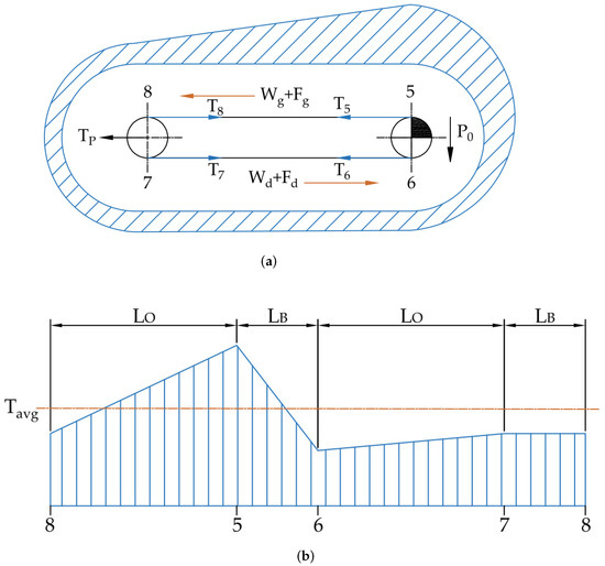
Figure 1.
Distribution of belt tensile force in the intermediate drive: (a) real distribution, (b) approximation adopted in the calculations.
The analysis of force in the belt of the intermediate drive is to determine the relationship between the and friction forces and the belt tensile forces measured at the return pulley of the . It is assumed that the forces and are equal, and their sum is the measured tension force of the driven belt. Therefore, it is possible to assess the effects of friction cooperation in the intermediate drive on the basis of changes in the tension force of the return pulley. The tensile forces at successive points of the driving belt loop, determined in the direction of belt motion, will be:
where is the tension force in the belt at the intermediate drive pulley entry point, is the tension force in the belt at the intermediate drive pulley exit point, is the tension force in the belt at the tail pulley entry point, is the tension force in the belt at the tail pulley exit point, is the friction force in the carry belt, is resistance to the motion of the carry belt, is peripheral force and is the tensile force (take-up).
The average belt tension force, assuming linear changes of forces between the points, is equal to:
where L is length of the loop of the intermediate drive belt, is length of the friction coupling section, is length of the belt at the pulley.
By introducing into Equation (4) the interrelations between the forces at marked points as a function of friction forces, resistances and peripheral force (1)–(3), it can be described as:
where and are the coefficients determining the ratios of the belt length in individual sections.
The consideration of the geometrical relation allows us to write Equation (5) in the following form:
In the next stage, it is necessary to consider the geometrical conditions and the average force in the belt caused by the take-up device:
where is the tensile force before starting the conveyor (defined as the force in the belt caused by take-up).
Performing an analogous cycle of calculations in the entire loop, but for the direction opposite to the belt movement, the force in the belt at individual points can be represented by the equation:
where is the friction force in the return side, is the resistance to motion of the return side.
Using similar substitutions as in Equation (5), the average tensile force of the belt can be defined as:
In the absence of friction coupling between the belts of the intermediate drive, i.e., for the operation of a separate drive, there is no transfer of the friction force (). By analyzing the variant of the decoupled drive, on the basis of dependences (8) and (12), it is possible to determine the resistance to motion of the carry side and the return side of the intermediate drive:
The dependencies (13) indicate the possibility of determining the resistance to motion of the intermediate drive separately for the carry and return side, based on the measurements of the peripheral force and changes in the tension force of the return pulley. The correctness of dependency (13) confirms:
The known values of resistance to motion with their division into the carry side and the return side allows us to estimate the value of the transmitted friction forces. To ensure traction of the belts in all possible drive operation states, the condition must be met [1]:
where is maximum friction force, is part of the resistance to motion of the intermediate drive, including the resistance of the return side and secondary resistance at the pulleys (without resistance to motion of the carry side, which are determined together with the resistance of the drive belt).
In the case of classic intermediate drives, where the belts are coupled only in the carry side of the conveyor, the friction force transmitted in the return side is equal to . The value of the friction force transmitted in the carry side can be determined by solving the following system of equations:
With the known values of the resistance to motion of the intermediate drive, determined in the previous step, we obtain the formula describing the transferred friction force in the carry side:
In the case of transmitting the friction force on both sides, the system of equations is correct:
The friction forces in the case of coupling at both sides are:
Accordingly, the resultant friction force can be written as:
On the basis of the derived dependencies, it is possible to determine the transmitted friction forces in the belts based on the measured values of the peripheral force on the intermediate drive and changes in the tension force of the return pulley (take-up system). Based on the theoretical assumptions presented above, research was carried out for two variants of the drive operation of the laboratory rig.
2.2. Test Rig
The test rig consists of two conveyors with flat belts (Figure 2). The main conveyor with a drive belt is 12 m long and equipped with a head drive (5.5 kW) and a tail (brake) drive (5.5 kW). The applied drive control system allows for braking in motion with the tail drive of this conveyor. The built-in intermediate drive conveyor with a driving belt is 5 m long. The drive of this 5.5 kW conveyor is located at the head pulley. The head pulley of the main conveyor and the head pulley of the intermediate drive are covered with a rubber lagging. The construction of the rig enables friction cooperation of both belts in two variants: the traditional solution with friction coupling only in the carry side and the new, analyzed solution with coupling on both sides. Over the 5 m length of the friction coupling section, both cooperating belts are supported by three idlers.
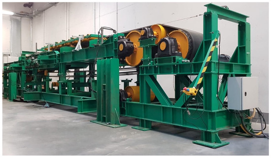
Figure 2.
General view of the test rig.
On both conveyors, a textile conveyor belt was installed, with a nominal strength of 250 kN/m and an area weight of 7.19 kg/m2. The width of the driving belt (intermediate drive) was set at 400 mm, and the width of the driven belt (main conveyor) at 400 mm. In the carry side, pressures are generated by the roller chain and the belt mass. In the return side, the pressures resulted only from the weight of the belt. Both conveyors have a screw-hydraulic tension pulley with load cells in the support of each bolt. The main changes in belt tensile forces are forced by hydraulic actuators. Adjustment with screws allowed to eliminate mistracking of the belt.
2.3. Equipment
During the tests on the rig, the following operating parameters were recorded: torque on the shafts of driving pulleys; tensile forces in two belts (on return pulleys); rotations of the intermediate drive pulley and the main conveyor return pulley (to determine the slip between the belts). The measurement of the torque was carried out with the use of a load cell on the torque arms of the transmission (Figure 3a). This type of assembly allows us to easily ignore the resistances of the transmission and measure the torque directly on the pulley. The transducers used make it possible to measure both the compressive and tensile force, i.e., the registration of the torque in two directions. It allows registering the state of driving and braking in steady motion. The peripheral forces on the pulleys are converted from the measurement of the forces on the torque arms, taking into account the length of these arms and the diameters of the pulleys (including the thickness of the rubber linings). The signs at the peripheral forces indicate the driving direction (positive, driving; negative, braking). Load cells were used to measure the tensile forces of the belts on the take-up pulleys (Figure 3b). Pulley rotation was measured with the use of encoders installed on the shafts (Figure 3c).
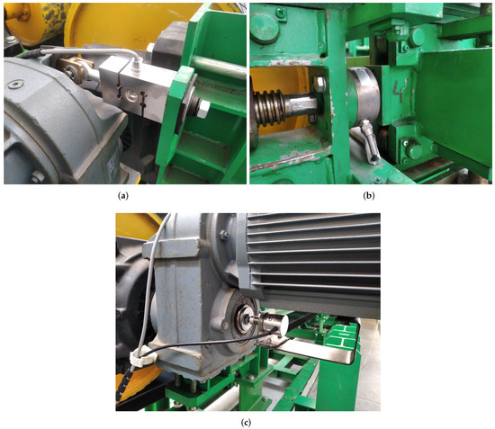
Figure 3.
Measuring system: (a) load cell on the torque arm of the transmission to measure the torque on the shaft of the drive pulley, (b) load cell for measuring the belt tensile force (compressive force on the cylinder piston rod), (c) incremental encoder on the shaft of the drive pulley for RPM measurement.
The resistance to motion of the rig is low and therefore the head drive of the main conveyor was excluded from use. In the presented series of tests, an intermediate drive on the head pulley and the return drive of the main conveyor operating in the braking system were used. This means that the conveyor was driven by the intermediate drive, and the drive at the return pulley of the main conveyor simulated increased resistance to motion. To enable such operating conditions, a vector control system for the operation of drive inverters was prepared. The data was processed using MATLAB software.
2.4. Methodology
The research consisted of measuring the operating parameters of the intermediate drive in two variants: with coupling only at the carry side (Figure 4a) and with coupling at both sides (Figure 4b). Points on the contours refer to the characteristic places where the belt tensile force changes. It is known from previous research that the optimal conditions of friction cooperation occur when the tensile force in the driving belt (intermediate drive) is greater than in the driven belt (main conveyor) [51]. The force ratio in the belts has a significant impact on the surface pressure between the friction belts and on the transverse vibrations of the belts [1,41]. The experimental conditions were established for the tensile force in the driving belt of 5 kN and the force in the driving belt of 2.5 kN (force ratio 2:1). The entire test cycle was carried out for the linear speed of the belts of 2.5 m/s.
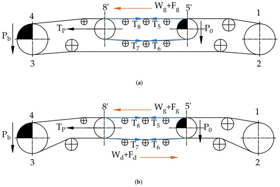
Figure 4.
Tested variants of the intermediate drive operation: (a) friction coupling carry belt, (b) friction coupling carry and return belt.
Figure 5 shows a measurement algorithm with successive steps and tasks.
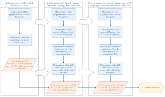
Figure 5.
Measurement algorithm.
First, measurements were made on a small conveyor forming an intermediate drive (without friction coupling with the main conveyor). Before starting the conveyor, the tension forces in the belts were established (as per the previous paragraph). After starting the conveyor, the peripheral forces at the driving pulleys, changes in the belt tension force at the return pulleys and rotations of pulleys were recorded. According to the Equations (13), on the basis of these measurements, it is possible to determine the resistance to motion of the carry and return side.
After determining the resistance to motion, basic measurements were started, which consisted of recording the previously discussed parameters of operation in the conditions of steady motion, where the braking torque was increased at the return pulley of the main conveyor. With the increase of the braking torque, simulating the increased resistance to motion of the main conveyor, the peripheral force at the intermediate drive increased until the belt traction was lost (slip). In a slip condition, the transmitted friction force reaches a maximum, approximately constant value. The intermediate drive operated in the scalar control mode, adjusting the torque to the current load and set revolutions. Measurement of the peripheral force and changes of belt tensile forces was used to determine the values of the transmitted friction forces, in accordance with the Equations (16) and (17). Measurement of pulley revolutions allows us to determine the point of loss of friction coupling between the belts. This is the point at which the measurement is deemed complete.
The initial state of the tests is work in steady motion without braking with the return pulley of the main conveyor. Then, the peripheral force on the only working return drive is in equilibrium with the total resistance to motion of the entire system. After imposing the braking torque (braking peripheral force ), the peripheral force of the intermediate drive increases by the value . An important parameter from the point of view of the energy efficiency of the system is the mechanical efficiency, which can be defined as:
where is the value of the peripheral force at the return (braking) pulley of the main drive and is the increase in the peripheral force of the intermediate drive as a result of the braking force .
Based on the known values of friction forces in the belts, the rubber–rubber friction coefficients were determined in accordance with the relation:
where is the maximum friction force and N is the normal force (resulting from the pressure of the belts).
The determined coefficient relates to the kinetic friction between the moving belts. A constant value of the belt pressure force in time was assumed. In the carry side, the pressure resulting from the weight of the roller chain and the belt was 944 N, while in the return side, it was 144 N (only belt weight).
3. Results
The results of measurements of the operating parameters of the short conveyor forming the intermediate drive are shown in Figure 6. Figure 6a shows the value of the peripheral force measured on the torque arm of the intermediate drive pulley, while Figure 6b shows how the belt tensile force has changed (at the take-up pulley). The measured peripheral force is the same as the resistance to motion of the entire intermediate drive conveyor and is approx. 30 N. The increase in the peripheral force should be consistent with the decrease in the tensile force at the tail pulley. This is because the average tensile force in the belt is constant and the length of the belt loop does not change. The obtained results confirm the correctness of this assumption. The measurements were carried out for a belt speed of 2.5 m/s, which was constant in all measurement series. The plots show the data from the load cells before the start of the conveyor, start-up and stable operation of the conveyor. The values recorded during the stable operation of the conveyor allow us to determine the resistance to motion of the return and carry side (Figure 6c), according to the system of Equation (13). It has been shown that the resistance to the motion of the carry belt is approx. 18 N, while the return belt is approx. 12 N.
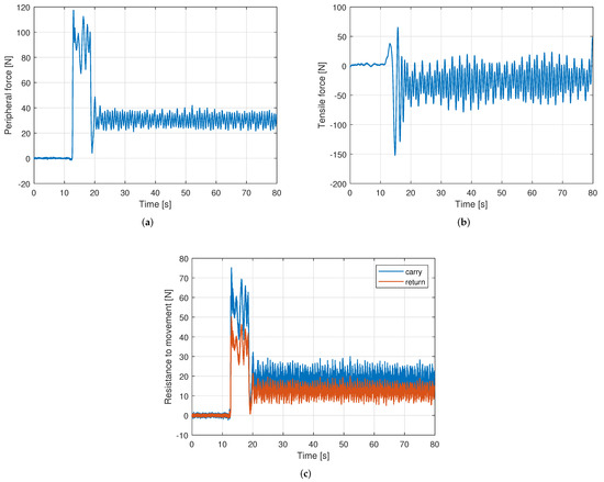
Figure 6.
Determination of resistance to motion of the intermediate drive belt sides: (a) peripheral force at the drive pulley, (b) change of the belt tensile force at the take-up (return) pulley, (c) resistance to motion of the carry and return side.
Figure 7 shows the time series of the peripheral force of the intermediate drive and the braking force at the return pulley of the main conveyor for two variants: with friction coupling only of the carry side (Figure 7a) and with coupling of both sides (Figure 7b). During these measurements, after starting the rig and stable operation, the braking torque was increased (negative values) and an increase of the peripheral force (positive values) was observed until the friction coupling was lost, which is related to the occurrence of a slip. The point of loss of friction coupling between the belts was determined based on the readings from the encoders. At the same time, there is a sudden drop in the measured forces and a change in the direction of motion. The resultant peripheral force of both drives determines the size of the total resistance to the motion of the rig (the sum of the resistance to motion of the main conveyor and the intermediate drive). In both drive cases, they are approximately equal. Working with the power transmission at the return side allows us to achieve a higher peripheral force and increase the load level of the intermediate drive before losing the the friction coupling and slip.
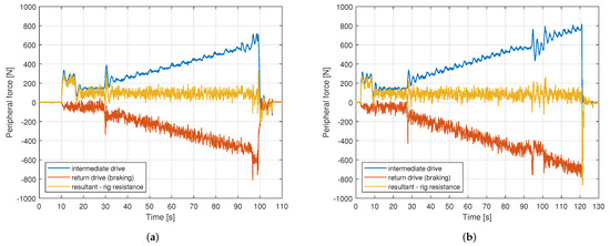
Figure 7.
Increase of the peripheral force at the intermediate drive, braking (main) drive and the resultant peripheral force of the system (resistance to motion of the entire conveyor): (a) for coupling at the carry side, (b) for coupling at the carry and return side.
However, a full assessment of the operating status requires an analysis of the force distribution in the belt. Figure 8 shows how the tensile force of the intermediate belt and the main conveyor belt changed for two variants of operation. A decrease of the intermediate belt tensile force is observed at the take-up pulley. For the assumption of a constant average belt tensile force, this means that the tensile force increases in the power transmission sections. In the case of coupling, it is only the carry side of the intermediate drive (Figure 8a); the increase of the tensile force on the transmission sections is smaller than for the variant of the coupling of the two sides (Figure 8b). At the same time, an increase of the tensile force of the main belt at the take-up pulley was observed. This means that the friction force was transferred from the intermediate belt to the main belt, and the intermediate drive takes the load of the main conveyor. These results are consistent with the theoretical assumptions of the intermediate drive operation without division into the number and type of power transmission sections.
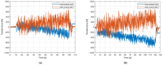
Figure 8.
Changes in the belt tensile force at the take-up (return) pulley: (a) for coupling at the carry side, (b) for coupling at the carry and return side.
In the case of the operation of two belts (Figure 9b), the transfer of the friction force is at both the carry and the return side. In the case of work of one belt (Figure 9a), the friction force is transferred only at the carry belt. In this case, it is also the resultant friction force for the entire system. The results shown in Figure 9 are based on the measured values, but the division into the intermediate drive sides is based on theoretical assumptions. Therefore, in the case shown in Figure 9a, no drive transmission at the return side was assumed. The increase of the friction force is the effect of the increasing braking torque at the tail pulley of the main conveyor. The courses of the resultant friction force from the load at the indirect drive are similar, which excludes the possibility of additional resistance to motion of the test rig. An unambiguous answer (not resulting from theoretical assumptions) about the usefulness of the new drive is shown in the dependencies in Figure 10. The resultant friction force for the work of one belt is 686 N, while for the work of two belts it is 786 N. The additional friction force of 100 N is thus caused by the lower belt engaging. The limits that determine the maximum transferable friction force are based on the rotations of the pulleys. The limit was set at the point where slip between the belts first occurred. The additional 100 N of friction force is a logical value taking into account the gravitational coupling of the two belts at the return side.
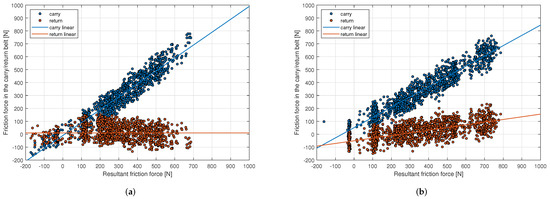
Figure 9.
Transmitted friction force: (a) for coupling at the carry side, (b) for coupling at the carry and return side.
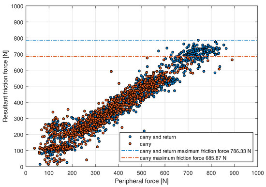
Figure 10.
Resultant friction force as a function of intermediate drive peripheral force for two work variants.
The kinetic friction coefficient determined according to Equation (23) for both considered cases is approx. 0.72. The averaged values of the coefficient of friction in relation to the peripheral force are shown in Figure 11.
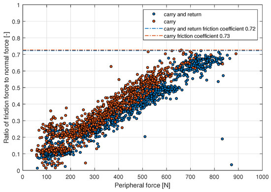
Figure 11.
Ratio of friction force to normal force as a function of intermediate drive peripheral force for two work variants.
The course of the efficiency defined by the relationship (23) as a function of the intermediate peripheral force is shown (Figure 12).
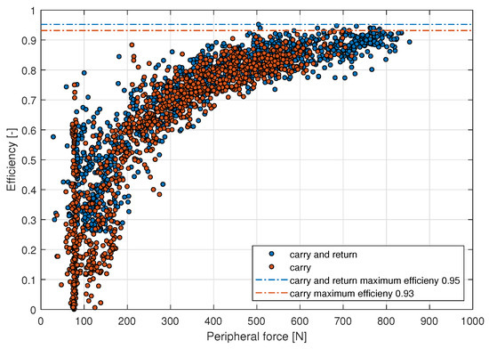
Figure 12.
Mechanical efficiency as a function of intermediate drive peripheral force for two work variants.
In the full peripheral force range of the intermediate drive, the new solution was on average 2 percentage points more efficient. The maximum efficiency of the solution with the coupling of the carry side is 0.93, while the solution with the coupling of both sides is 0.95.
4. Discussion
The research results indicate that the proposed method of assessing the effectiveness of the intermediate drive, based on the peripheral forces, tensile forces and rotations of the pulleys, is proper. Part of the research was to determine the resistances to motion of the intermediate drive, which were then converted into resistances at the carry and return side. A symmetrical division of resistance to motion was obtained due to the same method of supporting the belts in accordance with Figure 4. Due to the limited resistance to bending, the belt on the pulley and low primary resistance, the absolute value of resistance to motion was small due to the use of a flexible, textile belt with low strength [52].
The additional length of the friction coupling allows for higher peripheral forces and greater drive load before the loss of friction coupling and slipping (Figure 7b). The implementation of an additional coupling in the intermediate drive results in a larger contact surface. At the same time, a higher decrease in the tensile force at the return pulley of the drive was registered, which is synonymous with the increased transfer of the friction force by intermediate drive (Figure 8). The drive variant with the return side friction coupling does not increase the resistance to motion of the laboratory conveyor, which can be clearly seen in Figure 7.
In order to determine the correct distribution of friction forces, it is necessary to know about the tensile forces of the belt at characteristic points. This is a technical problem as there are only a limited number of measuring methods, and they generally require complicated equipment to be installed and have contact with the belt. There are solutions based on the [53] roller measurement system, but the method affects the resistance to motion of the test rig, which makes it impossible to apply due to the assumptions described in the research methodology. Due to the practical complexity of measuring the forces in the belt anywhere along their length, it is necessary to determine them on the basis of theoretical assumptions. The distributions in Figure 9 show that the new drive variant allows the power to be transferred also at the return belt. The value of the maximum possible transferable friction force at the carry side is similar for the two variants. For the variant shown in Figure 9b, however, we obtain a higher resultant friction force, which results from additional sections of the friction coupling at the return side. These results were clearly confirmed in Figure 10. The level of the possibility of power transmission is determined by the maximum friction force achieved when the belts lose their sticking friction, i.e., after reaching a slip. The return belt causes the slip to occur with a higher peripheral force for the same working conditions of the conveyor. For both variants, it was possible to achieve and register the operating states with slip, and to estimate the friction coefficient equal to approx. 0.72. The measured values of the coefficient are the same as the results obtained in other studies for the rubber–rubber friction pair [54,55,56]. Similar coefficients of friction for the two tested variants confirm the correct estimates of the normal force and the correctness of the measured operating parameters.
The operation of the intermediate drive with the return belt allows us to increase the efficiency in the full load range by an average of two percentage points. The maximum mechanical efficiency of the intermediate drive’s power transmission is 0.93 only at the carry side, and 0.95 at the carry and return side. This translates directly into the improvement of the unit energy consumption index for the reduced value of the tensile force of the belt and the transferred friction force [57]. The efficiency of standard intermediate drives in real working conditions is even higher, which results from the tests carried out in laboratory conditions at low loads, resulting from the technical limitations of the test rig [10].
Further research should focus on the analysis of the influence of tensile force ratios of the belts on the transferred friction force. The theoretical considerations of the authors on the work of such a drive lead to the hypothesis that there may be areas where the additional return belt does not transmit the drive power. Assuming that the necessary condition for the friction force transfer at the return side is creep at the carry side, braking states may occur for a low load [1]. Similar phenomena may take place at high loads, when the creep is so high that some of the energy is dissipated into elastic deformations (circulating power) [58]. It should be clearly emphasized that these are only assumptions that require validation in further research. The results presented in the article confirm that there are certainly work areas where this type of drive can be useful. Of course, the limitation of power transmission at the return side is always the normal force (resulting from the pressure of the weight of the intermediate belt on the main belt). Heavy-duty belts (e.g., steel belts) increase the value of the normal force at the return side. This solution can be useful in belt conveyors with several intermediate drives, where it is necessary to increase the power transmission, but it is not possible (e.g., due to the available space) to install a new drive. In this case, it is possible to use the return side of the intermediate drive at the already existing conveyor structure.
5. Conclusions
A theoretical and research analysis was carried out on a new solution of an intermediate drive of belt conveyors with a belt coupling at two sides. An algorithm to estimate the quality of the drive operation based on the registered basic parameters of the laboratory conveyor operation was shown and verified. The work quality of the intermediate drive is understood as the value of the friction force transmitted to the main conveyor belt, the distribution of tensions in the belts, the stability and efficiency of the system. The research also allowed us to determine the coefficients of friction of the rubber–rubber friction pair in the operating conditions of the conveyor. It has been shown that the theoretical assumptions for the operation of a standard intermediate drive are proper. It has been shown that for the tested parameters of the conveyor operation, the analyzed new drive structure is a beneficial solution. It allows us to increase the transfer of the friction force between the belts and to improve the mechanical efficiency of the intermediate drive. There are many theoretical assumptions and hypotheses for the operation of such a drive, which have been presented in the discussion section and will be the subject of further research. This type of drive can be an important supplement to underground conveyor lines, where, due to the limited space, the installation of a new drive is not possible, and it is possible to use the existing drive structure for the installation of return belt support. It will also contribute significantly to the reduction of investment and operating costs, including electricity consumption.
Author Contributions
Conceptualization, methodology: P.B., A.G., L.G., R.K. and M.O.; software and validation: P.B. and M.O.; writing—review, editing and supervision: L.G. and R.K.; project administration: A.G., L.G. and R.K.; final text prepared by P.B. and M.O. All authors have read and agreed to the published version of the manuscript.
Funding
The research work was funded with the research subsidy from the Polish Ministry of Science and Higher Education granted for 2022 and J.M. Voith SE Co. KG.
Institutional Review Board Statement
Not applicable.
Informed Consent Statement
Not applicable.
Data Availability Statement
Not applicable.
Conflicts of Interest
The authors declare no conflict of interest.
References
- Gładysiewicz, L. Belt Conveyors: Theory and Calculations; Oficyna Wydawnicza Politechniki Wrocławskiej: Wrocław, Poland, 2003. [Google Scholar]
- Yao, Y.; Zhang, B. Influence of the elastic modulus of a conveyor belt on the power allocation of multi-drive conveyors. PLoS ONE 2020, 15, e0235768. [Google Scholar] [CrossRef] [PubMed]
- Jennings, A.; Perrone, P.; Cornet, J. Case study: Correcting control problems on Essroc’s multidrive station, horizontally curved conveyor. Trans. Soc. Min. Metall. Explor. 2013, 334, 472–476. [Google Scholar]
- Mathaba, T.; Xia, X. Optimal and energy efficient operation of conveyor belt systems with downhill conveyors. Energy Effic. 2017, 10, 405–417. [Google Scholar] [CrossRef]
- Gładysiewicz, L.; Kawalec, W. Innovative long distance belt conveyor for transporting aggregates. Górnictwo Geoinżynieria 2009, 33, 137–150. [Google Scholar]
- Gładysiewicz, L.; Woźniak, D. The effective belt tension in short conveyor belt drives. Min. Sci. 2014, 21, 65. [Google Scholar]
- Alspaugh, M. Latest Developments in Belt Conveyor Technology; MINExpo 2004; Overland Conveyor Co., Inc.: Las Vegas, NV, USA, 2004. [Google Scholar]
- Weigel, T. On the application of belt-conveyor intermediate drives. Braunkohle 1981, 33, 367–369. [Google Scholar]
- Kulinowski, P.; Kasza, P.; Zarzycki, J. The Analysis of Effectiveness of Conveyor Belt Tensioning Systems. New Trends Prod. Eng. 2020, 3, 283–293. [Google Scholar] [CrossRef]
- Burgeth, B. Intermediate Drive Technology as a Cost-Saving Solution for Belt Conveyor Upgrades; University of Wollongong: Wollongong, Australia, 2019. [Google Scholar]
- Jurdziak, L.; Bajda, M.; Blazej, R. Estimation of purchase and replacement costs of conveyor belts and their splices in an underground mine based on their durability. In IOP Conference Series: Earth and Environmental Science; IOP Publishing: Bristol, UK, 2019; Volume 221, p. 012099. [Google Scholar]
- Yurchenko, V.; Nesterov, V. Non-reloading coal transportation in the eastern inclined shaft of “Raspadskaya” mine. In E3S Web of Conferences; EDP Sciences: Les Ulis, France, 2021; Volume 303. [Google Scholar]
- Hardygóra, M.; Żur, T. Belt Conveyors in Mining; Śląsk: Katowice, Poland, 1996; Volume 2, ISBN 8371640048. [Google Scholar]
- Kanus, M.; Hoffmann, A.; Overmeyer, L.; Ponick, B. Linear Direct Drive for Light Conveyor Belts to Reduce Tensile Forces. In Proceedings of the International Conference Cyber-Physical Systems and Control, Montreal, QC, Canada, 16–18 April 2019; pp. 398–406. [Google Scholar]
- Hötte, D.; Bindszus, L.; Overmeyer, L. Development of an Alternative Drive Concept for Belt Conveyors by Using Driven Idlers. In Proceedings of the Automated Systems and Technologies AST’2017, St. Petersburg, Russia, 14–15 June 2017; pp. 1–8. [Google Scholar]
- Walker, P.; Doroszuk, B.; Król, R. Analysis of ore flow through longitudinal belt conveyor transfer point. Eksploat. Niezawodn. 2020, 22, 536–543. [Google Scholar] [CrossRef]
- Szkudlarek, Z.; Sobolewski, A. T-T intermediate drive for a belt conveyor. Maszyny Górnicze 2019, 1, 66–72. [Google Scholar] [CrossRef]
- Trufanova, I.S.; Serzhan, S.L. Improving Transportation Efficiency Belt Conveyor with Intermediate Drive. Notes Min. Inst. 2019, 237, 331–335. [Google Scholar] [CrossRef]
- Gładysiewicz, L.; Konieczna, M. Theoretical basis for determining rolling resistance of belt conveyors. Min. Sci. 2016, 23, 105–120. [Google Scholar] [CrossRef]
- Lodewijks, G. A new generation of energy-saving belt conveyors. Transp. Przem. Masz. Rob. 2012, 3, 12–21. [Google Scholar]
- Masaki, M.S.; Zhang, L.; Xia, X. Cost optimization design approach for multiple drive belt conveyors. In Proceedings of the 2017 36th Chinese Control Conference (CCC), Dalian, China, 26–28 July 2017; pp. 2767–2772. [Google Scholar]
- Masaki, M.S.; Zhang, L.; Xia, X. A design approach for multiple drive belt conveyors minimizing life cycle costs. J. Clean. Prod. 2018, 201, 526–541. [Google Scholar] [CrossRef]
- Cała, M.; Szewczyk-Świątek, A.; Ostręga, A. Challenges of Coal Mining Regions and Municipalities in the Face of Energy Transition. Energies 2021, 14, 6674. [Google Scholar] [CrossRef]
- Breido, I.; Intykov, T.; Daniyarov, N.; Kelisbekov, A.; Semykina, I.Y. Mathematical model of apron conveyor controlled Electric drive in operation starting modes. Geol. Tech. Sci. 2019, 3, 232–238. [Google Scholar] [CrossRef]
- Hoffmann, A.; Kanus, M.; Overmeyer, L.; Ponick, B. Integrated Linear Flux Modulating Motor for a Direct-drive Belt Conveyor. In Proceedings of the 2021 13th International Symposium on Linear Drives for Industry Applications (LDIA), Wuhan, China, 1–3 July 2021; pp. 1–6. [Google Scholar]
- Feng, Y.; Zhang, M.; Li, G.; Meng, G. Dynamic characteristic analysis and startup optimization design of an intermediate drive belt conveyor with non-uniform load. Sci. Prog. 2020, 103, 0036850419881089. [Google Scholar] [CrossRef]
- Chichenev, N. Import-replacing re-engineering of the drive of the rollers in the intermediate roller table of a continuous bloom caster. Metallurgist 2015, 58, 892–895. [Google Scholar] [CrossRef]
- Sruthi, M.; Nagamani, C.; Ilango, G.S. An improved algorithm for direct computation of optimal voltage and frequency for induction motors. Eng. Sci. Technol. Int. J. 2017, 20, 1439–1449. [Google Scholar] [CrossRef]
- Semykina, I.Y.; Tarnetskaya, A. Control of energy efficient belt conveyor gearless drummotor. EAI Endorsed Trans. Energy Web 2019, 6, 22. [Google Scholar] [CrossRef][Green Version]
- Dwivedi, S.K.; Laursen, M.; Hansen, S. Voltage vector based control for PMSM in industry applications. In Proceedings of the 2010 IEEE International Symposium on Industrial Electronics, Bari, Italy, 4–7 July 2010; pp. 3845–3850. [Google Scholar]
- Maron, T.; Rausch, C. Underground conveyor system between two coal mines in the Czech Republic. Min. Rep. 2014, 150, 85–89. [Google Scholar] [CrossRef]
- Bajkov, D. Experimental research into intermediate transmission for belt conveyors. Ann. Mines Belg. 1980, 1, 5145896. [Google Scholar]
- Popescu, N.; Dinu, R.; Mircea, I. Conveyor Energy Efficiency Parameter Determination Using Matlab–Simulink. J. Sustain. Energy 2013, 4, 43–46. [Google Scholar]
- Banaszak, A.; Laska, Z. Development and exploitation of belt conveyors transport scheme based on 30 years of belt transport department activity in Rudna Mine. Transp. Przem. Masz. Rob. 2008, 1, 42–48. [Google Scholar]
- Trufanova, I.; Avksentiev, S. Mathematical model of belt conveyor intermediate drive with baffles. In IOP Conference Series: Earth and Environmental Science; IOP Publishing: Bristol, UK, 2019; Volume 378, p. 012033. [Google Scholar]
- Trufanova, I.; Lavrenko, S. Elaboration of the mathematical model of the intermediate linear drive belt with pressure rollers. ARPN J. Eng. Appl. Sci. 2016, 11, 11581–11583. [Google Scholar]
- Alspaugh, M. The evolution of intermediate driven belt conveyor technology. Bulk Solids Handl. 2003, 23, 168–172. [Google Scholar]
- Makharatkin, P.; Avksentev, S.; Trufanova, I. Development and improvement of conveyor transport in the conditions of complicated operation in modern mining industry. Zesz. Nauk. Organ. Zarzkadzanie Politech. Slkaska 2016, 91, 229–240. [Google Scholar]
- Goncharov, K. Determination of relative immobile and sliding areas between carrying and tractive belts in using of belt conveyor intermediate drives. Nauchno Tekhnicheskiy Vestn. Bryanskogo Gos. Univ. 2015, 2, 66–70. [Google Scholar]
- Reutov, A. Modeling of Conveyor Belt Drives: Monograph; BSTU: Bryansk, Russia, 2011. [Google Scholar]
- Goncharov, K.; Grishin, A. Theoretical study of influence of belt tension of intermediate belt conveyor drive on value of zone of relative slip of traction and carrying belts. In IOP Conference Series: Earth and Environmental Science; IOP Publishing: Bristol, UK, 2017; Volume 87, p. 022008. [Google Scholar]
- Goncharov, K.; Grishin, A. Experimental investigation of traction and load-carrying belt tension impact upon intermediate drive tractive ability of belt conveyor. Vestn. Bryanskogo Gos. Tech. Univ. 2018, 98–109. [Google Scholar] [CrossRef]
- Trufanova, I.; Lavrenko, S. The efficiency improvement of belt conveyor intermediate drive traction effort. ARPN J. Eng. Appl. Sci. 2016, 11, 4317–4321. [Google Scholar]
- Bahke, T. Sizing and employment of conveyor belt systems with intermediate drive for the carrying/drive belt (TT drive). Braunkohle 1981, 33, 7059357. [Google Scholar]
- Snovedskiy, Y.M.; Kravinskiy, G. Creation of a Test Stand for a Belt Intermediate Drive of a Conveyor with Ferromagnetic Traction Mechanism; OSTI: Oak Ridge, TN, USA, 1980; p. 6123594. [Google Scholar]
- Gładysiewicz, L.; Król, R. Improving belt conveyor transportation within cooperation with KGHM ZANAM S.A. Cuprum Czas. Nauk. Tech. Gor. Rud 2016, 2, 35–47. [Google Scholar]
- Gładysiewicz, L.; Woźniak, D.; Kisielewski, W. The idea and tests of the Rope Booster Drive of a belt conveyor. Transp. Przem. Masz. Rob. 2013, 2, 20. [Google Scholar]
- Gładysiewicz, L.; Woźniak, D. Tests of coefficient of friction for the purpose of modeling the effective transmissible tension of a conveyor belt with an intermediate belt drive. Transp. Przem. Masz. Rob. 2011, 4, 19–23. [Google Scholar]
- Zhironkin, S.; Szurgacz, D. Mining Technologies Innovative Development: Economic and Sustainable Outlook. Energies 2021, 14, 8590. [Google Scholar] [CrossRef]
- Gursky, V.; Kuzio, I.; Krot, P.; Zimroz, R. Energy-saving inertial drive for dual-frequency excitation of vibrating machines. Energies 2020, 14, 71. [Google Scholar] [CrossRef]
- Gładysiewicz, L.; Kisielewski, W.; Woźniak, D.; Król, R.; Kaszuba, D. Friction coupling in a rope intermediate drive. Transp. Przem. Masz. Rob. 2014, 1, 31–35. [Google Scholar]
- Bajda, M.; Krol, R. Experimental tests of selected constituents of movement resistance of the belt conveyors used in the underground mining. Procedia Earth Planet. Sci. 2015, 15, 702–711. [Google Scholar] [CrossRef][Green Version]
- Yao, M.; Jin, Y.; Zhao, M.; Xu, S. Research and Application of Heavy-Equipment Parachute Rope Tension Sensor. J. Sens. 2018, 2018, 7631727. [Google Scholar] [CrossRef]
- Guntermann, A. Problems concerning the drive mechanism and auxiliary drive belt-current state of research work and practical experience. Braunkohle 1981, 33, 5605540. [Google Scholar]
- Kasza, P.; Kulinowski, P.; Zarzycki, J. The Influence of an Operating Conditions on the Friction Coefficient in Transportation Machines Drives. New Trends Prod. Eng. 2020, 3, 294–302. [Google Scholar] [CrossRef]
- Kulinowski, P.; Kasza, P.; Zarzycki, J. Identification of the operating parameters of the friction drum drive in industrial conditions. Eksploat. Niezawodn. 2021, 23, 94–102. [Google Scholar] [CrossRef]
- Mahlia, T.M.I.; Yanti, P.A.A. Cost efficiency analysis and emission reduction by implementation of energy efficiency standards for electric motors. J. Clean. Prod. 2010, 18, 365–374. [Google Scholar] [CrossRef]
- Kagotani, M.; Aida, T.; Koyama, T.; Sato, S.; Hoshiro, T. Some methods to reduce noise in toothed belt drives. Bull. JSME 1981, 24, 723–728. [Google Scholar] [CrossRef][Green Version]
Publisher’s Note: MDPI stays neutral with regard to jurisdictional claims in published maps and institutional affiliations. |
© 2022 by the authors. Licensee MDPI, Basel, Switzerland. This article is an open access article distributed under the terms and conditions of the Creative Commons Attribution (CC BY) license (https://creativecommons.org/licenses/by/4.0/).