Article

PLC Physical Layer Link Identification with Imperfect Channel State Information

by
Javier Hernandez Fernandez
1,2,*,
Aymen Omri
2 and
Roberto Di Pietro
1
1
Division of Information and Computing Technology, College of Science and Engineering, Hamad Bin Khalifa University, Doha P.O. Box 5825, Qatar
2
Iberdrola Innovation Middle East, Doha P.O. Box 210177, Qatar
*
Author to whom correspondence should be addressed.
Energies 2022, 15(16), 6055; https://doi.org/10.3390/en15166055
Submission received: 6 April 2022 / Revised: 28 April 2022 / Accepted: 3 May 2022 / Published: 21 August 2022
(This article belongs to the Section F: Electrical Engineering)

Abstract

:
This paper proposes an accurate physical layer technique to uniquely identify the links of a power line communication network. First, the power line communications (PLC) multipath channel characterization is presented and detailed. Then, a multipath channel delay detection technique is introduced to provide an accurate physical layer identification (PL ID) for the considered PLC links. The accuracy and efficiency are tested by evaluating the successful path detection probability (SPDP) in a simulated scenario under both perfect and imperfect channel state information conditions. The results confirm the advantages of the proposed scheme. Indeed, for a common PLC noise power around 90 dBuV, the provided accuracy reaches ≈ 90 % , while for a noise power below 80 dBuV, the accuracy plateaus at 100 % . Overall, the low complexity of the proposed approach and its staggering performance results pave the way for further possible applications in both the PLC and the security domain.

1. Introduction

Power line communication (also known as power-line carrier or PLC) has been proposed as a promising solution to support smart grid applications, such as the identification of losses, asset mapping, fault detection, or aiding in securing networks and devices [1,2,3].
When applied to the electrical grid, one of the inherent advantages of PLC is the ability to use the signals to provide information about the power grid itself. Exploiting the transmission medium’s physical properties proved to be an efficient tool, particularly in wireless networks, where the use of the channel state information (CSI) provides fine-graded information with sufficient entropy to sustain efficient security services. Most of such techniques have not been adapted to the power line medium due to their inherent differences. Indeed, wireless network security schemes rely on reciprocal channel characteristics in constant change due to nodes’ mobility and the changing environment [4,5]. Conversely, power line transmission has no mobility of the communicating nodes, no changes to the environment, and it does not offer channel state information reciprocity—with the exception of the channel path delays [6]. Communication impairments and the general lack of symmetry of the power line channel have hindered the adoption of physical-layer-based security mechanisms.
The vast, diverse, and mostly unmonitored infrastructure of power cables delivering energy from generation sources to household outlets constitutes a potential security vulnerability. Current PLC protocols being deployed in the field, such as PoweRline Intelligent Metering Evolution (PRIME), G.hnem, G.hn, or HomePlug AV2, are being secured in the upper layers using traditional public key infrastructure (PKI) and advanced encryption standard (AES) schemes [7]. In this context, non-cryptographic physical security mechanisms can utilize device hardware, software, or location/channel-specific properties to secure communications. Channel properties, such as the CSI and the received signal strength (RSS), are dependent on location and therefore eligible for identification purposes in PLC communications. The cited physical layer identification techniques take advantage of the unique channel signature between two communicating devices to extract a fingerprint. In PLC, the multipath channel delays are the sole fully reciprocal parameters dependent only on the network’s topology [8,9]. Unlike the rest of the information that can be extracted from the channel, the multipath channel delays obtained from the channel impulse response (CIR) are able to provide fine-grained and symmetric contextual information suitable for physical layer security (PLS) purposes.
The number of applications where the PLC signals fingerprint is used is broad, ranging from pure communication systems to network management and security. The analysis conducted in this paper on the related literature shows that the vast majority of the cited corpus is based on the assumption of having a perfect CSI, disregarding the imperfections and uncertainty one has to face when confronted with real-world scenarios. In addition relying on perfect channel conditions, the number of applications focusing on security, and more specifically PLS, is limited, most probably due to the topic’s relative novelty. Several solutions using PLC signals exist, primarily for topology inference, but few for security applications. Based on the findings from the literature review presented in the related work section, three general conclusions can be drawn on the status of the CIR-based physical layer techniques in PLC:
  • Full reciprocity of the measured signals can only be found in topology-dependent CIR path delays.
  • CIR-based solutions tend to assume perfect channel conditions and neglect the effect of impulsive noises.
  • Key generation schemes are the only existing PLS mechanisms taking advantage of the path delays.
In light of the mentioned issues, we provide the following contributions.
Contributions We propose an accurate scheme to generate unique identifications of the links connecting PLC nodes. The proposed CSI-based method improves the estimation error of the CIR under imperfect channel conditions allowing an accurate identification. The results indicate that for the noise power range between 80 dBuV and 90 dBuV, a path detection gain of more than 80 % can be observed with respect to a state-of-the-art competing solution. For noise levels below 80 dBuV our solution provides 100 % accuracy. To the best of our knowledge, this is the first work in the literature that treats the PLC channel estimation error to provide an accurate physical layer identification scheme.
Paper Organization The sequel of the paper is organized as follows. Section 2 presents the related work. The PLC channel characteristics and modeling are detailed in Section 3. Section 4 describes the proposed power line (PL) identification scheme under imperfect CSI. In Section 5, we present the simulation’s results and discussion. Finally, conclusions are drawn in Section 6.

2. Related Work

Critical grid infrastructure elements, because of their geographical spread and their ongoing transformation due to automation and digitalization, are naturally exposed to physical, cyber, and human attacks [10]. IDPSs (Intrusion detection and prevention systems) combine general security mechanisms developed for cyber-physical systems (CPS) with those specific for each industry. The authors of [11] analyze and classify 37 smart grid IDPS by detection technique, offering a broad idea of the vast ecosystem of currently available solutions. Some applications rely on PLC simply as a communication means, such as smart metering [12,13,14], energy loss detection [15,16,17], topology estimations [18], or grid management [19,20]. Others take advantage of the sensing capabilities of the PLC communication signal to obtain real-time information of the power grid itself. PLC signal-based network diagnosis is widely used to detect non-technical losses [21,22], anomalies in the grid [23,24,25], or even as input for a Machine-Learning-based intrusion detection system [26]. Given its importance for utilities, topology recognition is one of the most researched topics, with a wide range of techniques available.
The remainder of this section summarizes the PLC signal-based existing solutions classified by the processing domain on which they operate. The analysis has been limited to non-machine-learning-based approaches.
  • Time-Domain Solutions: In [27,28], a single-point reflectometry technique has been proposed for grid diagnosis in the automotive sector. The implementation uses a signal bandwidth from 300 MHz to 500 MHz, but it is intended only for short cables [29] and does not consider the impact of impulsive noise. Another technique has been proposed in [30] for low voltage (LV) topology estimations, using a signal ToA (Time of Arrival) two-way handshake. The solution requires a device at every endpoint [31], which presents a limitation of this work. In [32], a multi-point reflectometry with order statistics–constant false alarm rate (OS-CFAR) detector [33] has been proposed for general topology estimation, assuming that the PLC noise follows a Gaussian distribution. In addition, it requires reflection measurements at multiple cable ends and should determine all possible graphs for each iteration, which significantly increases the algorithm complexity. The authors of [34] define a topology identification method for indoor PLC. The solution employs the ToA of signals but does not consider the effect of imperfect CSI and impulsive noise. The work in [6] introduces a one-level CIR quantization solution for physical layer key generation, but it does not account for the negative impact of the channel estimation errors and, in some cases, might suffer from the obvious low entropy given by the infrequent changes in power line topology. In [35], a power line noise-based key generation has been proposed for pairing and authenticating IoT devices. The technique is based on contextual pairing and, therefore, has the drawback of not effectively rejecting malicious devices with access to the local power line. A single-point-reflectometry-based non-parametric method has been proposed in [36]. This technique uses the inverse Fourier transform of frequency domain (FDR) measurements for topology estimation in LV environments. As mentioned by the authors, single-point reflectometry systems are limited by the power line lengths, the number of branches, and the time-frequency uncertainty.
  • Frequency-Domain Solutions: The authors of [6] propose a key generation technique based on the transmission matrix estimation requiring the exchange of the channel input impedance values between devices. In [37,38], the authors present different PLS key generation techniques using the channel frequency response (CFR). The assumptions of a perfect CSI and a high CFR symmetry present a limitation to these techniques. An EMI-based PLS key generation has been proposed in [39]. It is designed for systems where the devices are close enough to observe the same noise patterns. In [36,40], single-point reflectometry is used for LV topology estimation, and grid diagnostics. The required measurements are limited by distance, and by the number of branches due to the attenuation of signals [29]. In addition, computational complexity increases exponentially with the number of measured reflections [30,31].
  • Time-Frequency-Domain Solutions: Topology estimation, PLC routing, and grid diagnosis applications are covered in [29,41] using a combination of signal arrival times but excluding the impact of impulsive noise. Single-point reflectometry is used in [31], where a node-by-node greedy algorithm is used for topology reconstruction and impulsive noises are used for dynamic re-estimations of the topology. The authors of [42] present end-to-end sensing and reflectometry algorithms to capture the topology of the power networks, as well as to monitor load changes, cable degradation, and faults. In addition to detecting and locating faults, the proposed solution classifies the anomalies between load impedance changes and local/distributed faults. A continuation of the previous work can be found in [25] with solutions employing single-point and multi-point reflectometry for grid diagnostics. The proposed techniques are not considering the impact of the channel estimation errors on the grid diagnostics accuracy.
In Table 1, we present a summary of all reviewed PLC signal-based solutions categorized by technique, application, and environment. The focus of this paper will revolve from this point onwards around the time domain, as path delays are the only reciprocal parameter available in PLC.
To the best of our knowledge, despite the considerable work performed in the areas of security, IDPS, and extended uses of PLC smart meters, no solutions propose a method to improve PLC channel estimation errors under imperfect channels.

3. PLC Channel Characteristics and Modeling

This section introduces the PLC multipath channel characteristics and modeling concepts that will be instrumental for the sequel of the paper.

3.1. PLC Multipath Characteristics

Multipath propagation occurs due to the signal reflections at branching points, cable joints, and terminations [43]. These replicas of the transmitted signal, caused by impedance mismatches, will generate new paths extending in all possible directions. As each new propagation path will encounter more reflections, the number of directional paths will continue to grow exponentially, only limited by the signal decay produced by the transmission and reflection losses. Therefore, communicating devices will receive a set of delayed and attenuated signals. A key observation, leveraged throughout this work, is that the collection of the path arrival times, from the first multipath components to the last significant one, can be used to create a path delay profile between a transmitter and a receiver.
The following subsections explore the PLC path delay profiles’ reciprocal characteristics and how topological changes in the power line impact them.

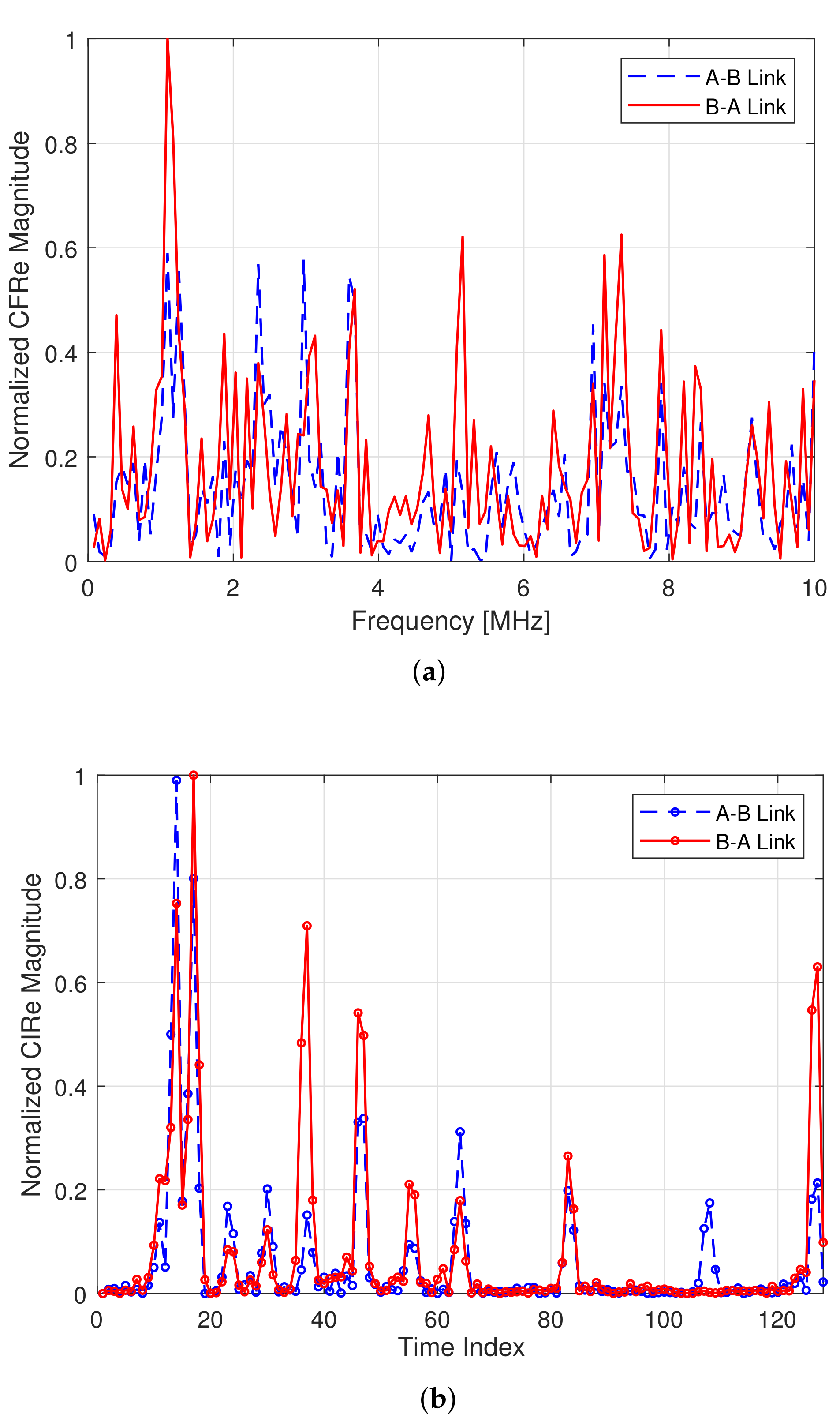
3.1.1. Reciprocal Observations in PLC CIR

The PLC channel multipath delays present reciprocity in terms of path delays [6]. This wide-sense symmetry of topology-invariant channels analysis is detailed in Appendix A of the work presented in [6]. It shows that the time domain response of two corresponding channels between two points/ports is not strictly symmetric but wide-sense symmetric. This implies that the channel’s multipath response is characterized by peaks in the same positions both when the signal travels from port 1 to port 2 and vice versa. However, the amplitude of the peaks and their shape are, in general, different; thus, the PLC channel is not strictly symmetric. As an example, Figure 1 shows the normalized channel frequency and impulse response magnitudes of a given PLC channel in both communication directions [8]. It can be noted that the channel frequency response is far from symmetric, even though a certain degree of correlation still exists. Instead, a stronger correlation is evident when considering the time domain, as per Figure 1b. Even though the impulse peaks’ amplitude is somewhat different, one can see that their position is the same. The mismatches are due mainly to three main reasons: (i) the presence of high power line noise, especially impulsive noise; (ii) the accuracy of the peak detection algorithm; and lastly (iii), the signal sampling time, which has a strong influence on the estimation of the presence and position of the peaks, rendering some peaks undetectable. In this work, we have considered all the cited CSI imperfections.

3.1.2. The Effect of Topology in Path Delays

A comprehensive study of the power line topology influence in PLC can be found in [44,45,46,47,48]. The authors examine the impact that cable lengths, branches, and impedances have on the CIR and the CFR. Figure 2 shows the standard T network structure, consisting of a direct connection between two communicating devices, edges A and B, and a middle branch with a termination point D, where h ( t ) presents the CIR magnitude, and τ i is the path i delay.
The theoretical behavior of multipath delays due to the most common topology changes can be summarized as follows:
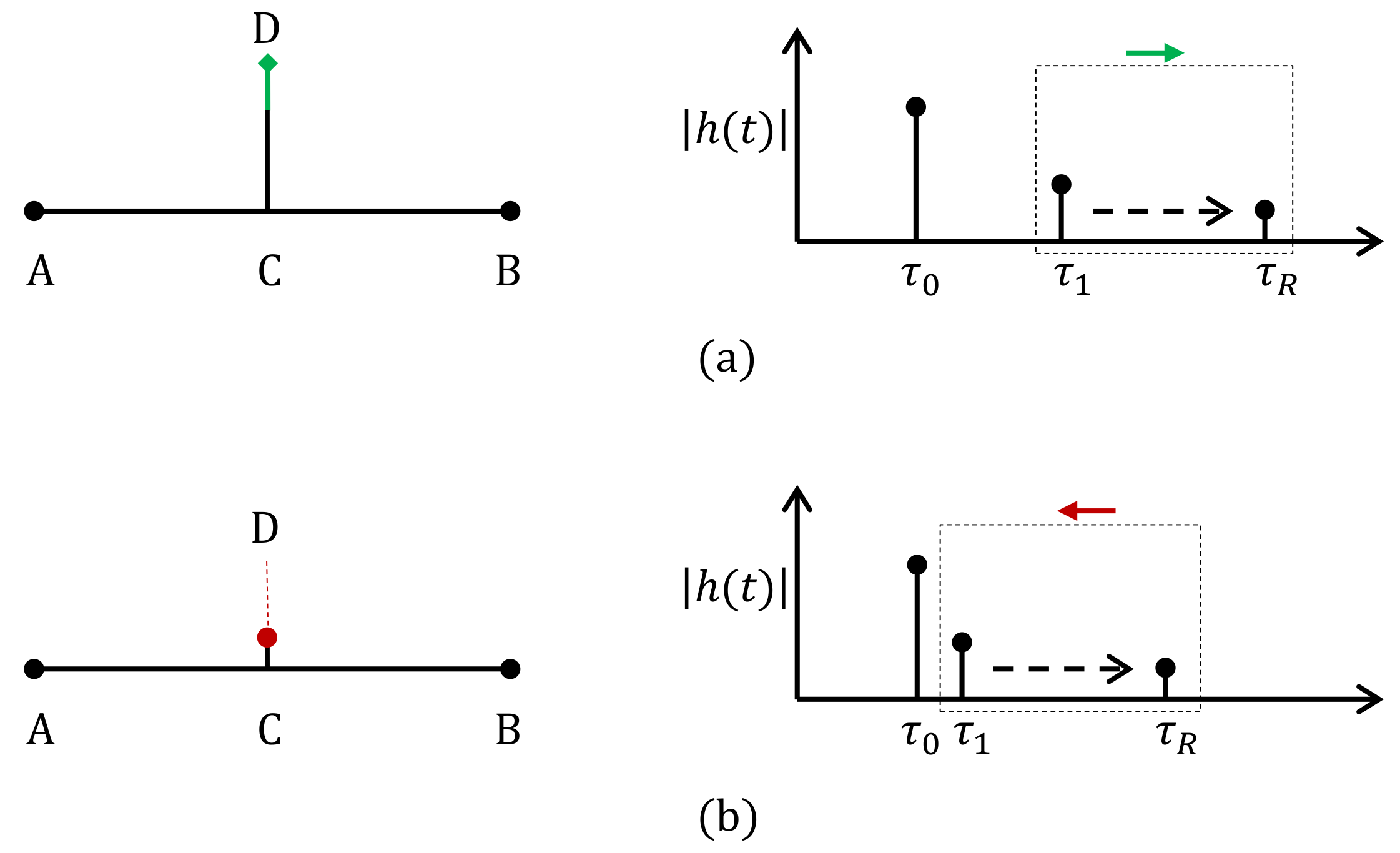
  • Distances between communicating nodes: An increase in the distance between the transmitter and receiver nodes is accompanied by an increment in all multipath components’ arrival time. Conversely, a decrease in the length will reduce the arrival time of the path delay impulses. Figure 3 depicts both behaviors.
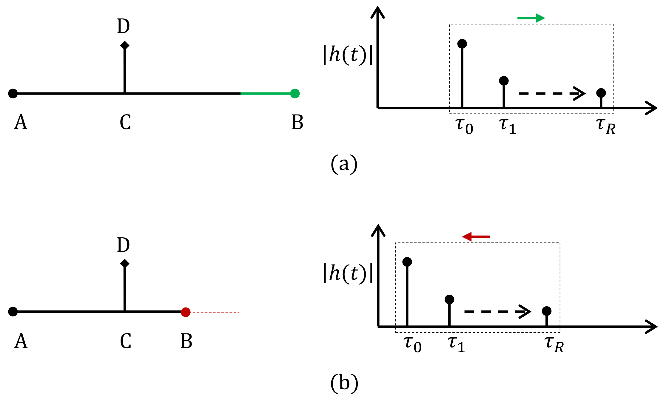
  • Length of branches: An increase in the length of a branch between two communicating nodes will not affect the first detectable signal’s arrival τ 0 . The remaining multipath components will experience a delay (extension) or an advance (shortening). The above, represented in Figure 4, will hold for the general cases, where the distance between the branch is lower than the distance between the segment.
  • Number of branches: Adding or removing branches to the same node or along the power line will represent an increase or decrease, respectively, in the number of path delays as shown in Figure 5.
It should be noted that changes in impedances, produced directly by the network loads or indirectly by topology changes, do not influence the path delays. However, since the signals’ attenuation is affected, it could impact the significant path delay profile if the signal levels fall below the receiver’s sensitivity. Due to the reciprocity of the path delay, the loss of this multipath component will occur in both the transmitter and receiver simultaneously.

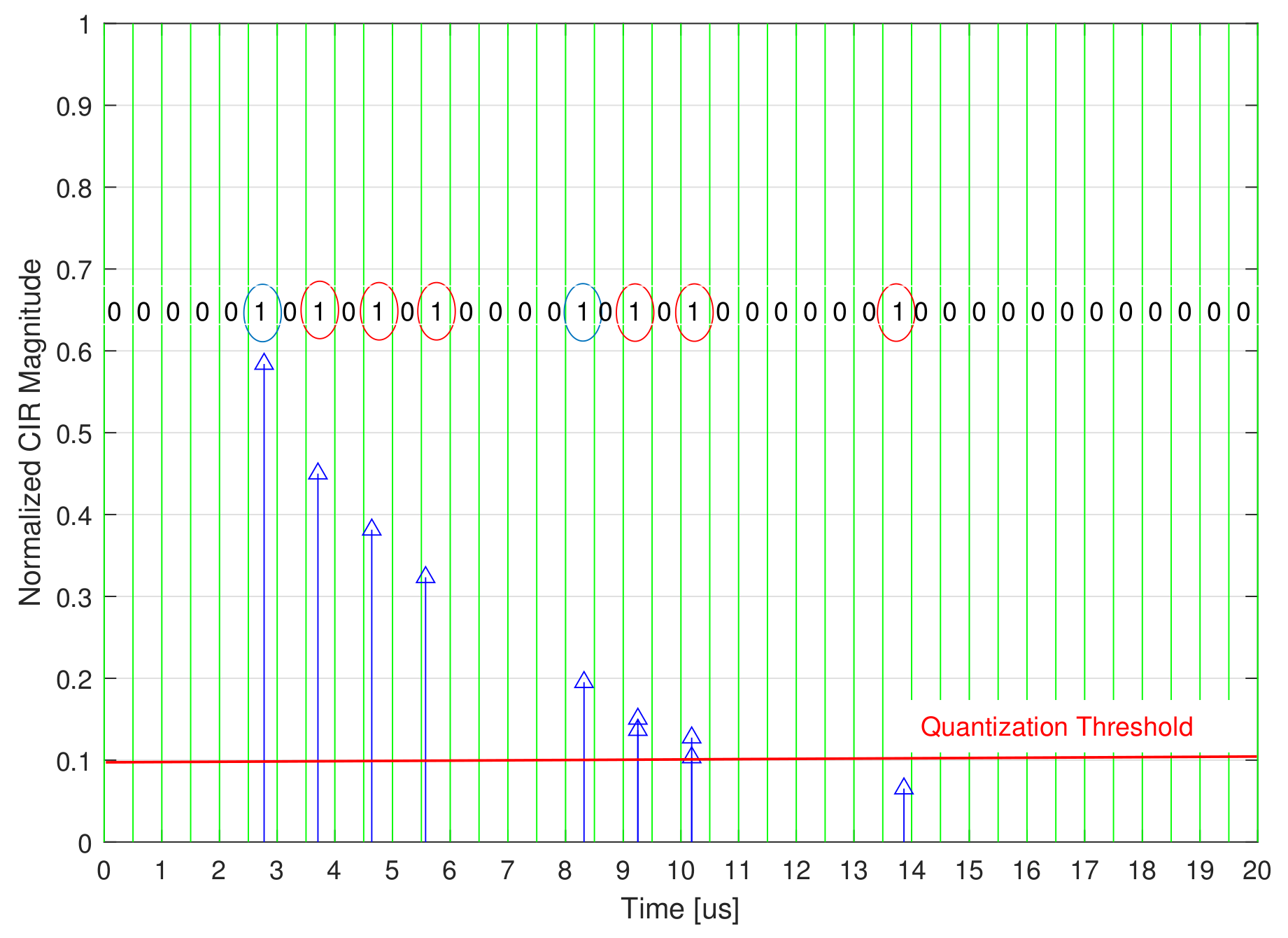
3.1.3. Path Delay Detection Resolution

The PLC channel multipath delays can be identified by the corresponding CIR. Accordingly, the path delays detection resolution is highly related to the accuracy of the CIR, which is proportional to the used sampling frequency. Therefore, by increasing the sampling frequency, the path delays detection resolution can be improved, which increases the possibility to detect all the available paths, even the ones generated by near nodes.
To clarify the above, let us consider a scenario, such as the one in Figure 6, where a single cable connects nodes A, B, and E in a daisy chain. Let d A B be the distance between A and B, and d B E be the distance between B and E, with | d A B | < | d B E | . We define F s a m p as the sampling frequency, C as the speed of light, v p = 0.6 C as the power line signal propagation speed, and d as the detection resolution in meters. Here, the detection resolution is defined as the minimum distance between two detected adjacent nodes.
The propagation times for the direct path ( A B ) and the second path ( A B E B ) can be computed as t 0 = d A B / v p and t 1 = ( d A B + 2 d B E ) / v p , respectively. In order to detect both paths at node B, a minimum sampling time of T s a m p ( t 1 t 0 ) is needed. Otherwise, the second path will not be detected. Consequently, the F s a m p needed to detect both paths must satisfy the following:
1 F s a m p ( t 1 t 0 ) 2 d B C v p .
The above inequality can be rewritten as follows:
d B C v p 2 F s a m p 0.3 C F s a m p .
Hence, for a given sampling frequency F s a m p , the minimum distance between two detected nodes is equal to:
d = 0.3 C F s a m p ,
which provides us with the path delay detection resolution that can be used to evaluate the limits of a PLC system in detecting adjacent nodes. Existing PLC standards use bandwidths extending from a few kHz on the NB-PLC solutions to the MHz of the BB-PLC [7]. As expected, Equation (3) confirms in a precise manner that the detection resolution value increases by decreasing the sampling frequency; therefore, BB-PLC obtains a better detection accuracy—it could be in the range of a few meters or even centimeters. For instance, a very high sampling frequency above 200 MHz [49,50] would yield a detection resolution d below 50 cm.

3.2. PLC Multipath Channel Model

A set of four scenarios, presented in Figure 7 and capturing the major different theoretical behaviors of multipath delays introduced in the previous section, are used to simulate the impulse responses. The PLC time-domain model introduced in [8] is used to generate the corresponding path delays and gains for each of the scenarios.
Let us start analyzing the first scenario that is presented in Figure 7a, the baseline scenario, where a node A is connected directly to a node B, without any discontinuity. For this configuration, the signal follows a first direct path ( A B ) and a virtually infinite number ( i = 1 , , ) of secondary paths arising from the signal bouncing between A and B i times. That is, for the first direct path, when i = 0 , we have the path ( A B ). Then, for the second path (first bounce, i = 1 ), we have ( A B A B ), etc. Let L X Y denote the general distance between two given nodes X and Y, α denote the propagation attenuation coefficient per power line length unit, ρ X denote the reflection attenuation coefficient at node X, and δ X denote the discontinuity attenuation coefficient at node X.
By considering the different aforementioned attenuations, the corresponding path lengths l i and weights g i for Scenario 1 can be given by Table 2—we decided to stop tabulation at i = 9 , considering the remaining secondary paths contributions as negligible; an assumption supported by the standard equations for attenuation.
Accordingly, we developed a script to exhaustively identify the significant paths and the corresponding delays and gains for each scenario. Using the same analysis, we have evaluated the power delay profiles of the remaining scenarios, as presented in Table 2 and Figure 8, Figure 9, Figure 10 and Figure 11.

4. Physical Layer Identification Scheme Description

Based on the PLC multipath characteristics and modeling presented in the previous section, we introduce an accurate physical layer identification scheme (PL ID) for the fingerprinting of the different links between the nodes existing on the grid, implemented by leveraging a realistic imperfect CSI. In a nutshell, the proposed method entails employing multiple successive estimated CIRs over time to minimize noise effects [51,52]. In fact, it is known that the PLC channel is slow fading and therefore almost invariable in time. We assume that the channel estimation error follows a random distribution with zero mean, i.e., on any collected data point, the channel estimation error can be a negative or a positive value, but their sum adds up to an absolute value close to zero. As a result, the average of the different CIRs can be used to reduce the channel estimation errors.
Accordingly, we present in Algorithm 1 the PL ID scheme, which consists of the following three main Steps:
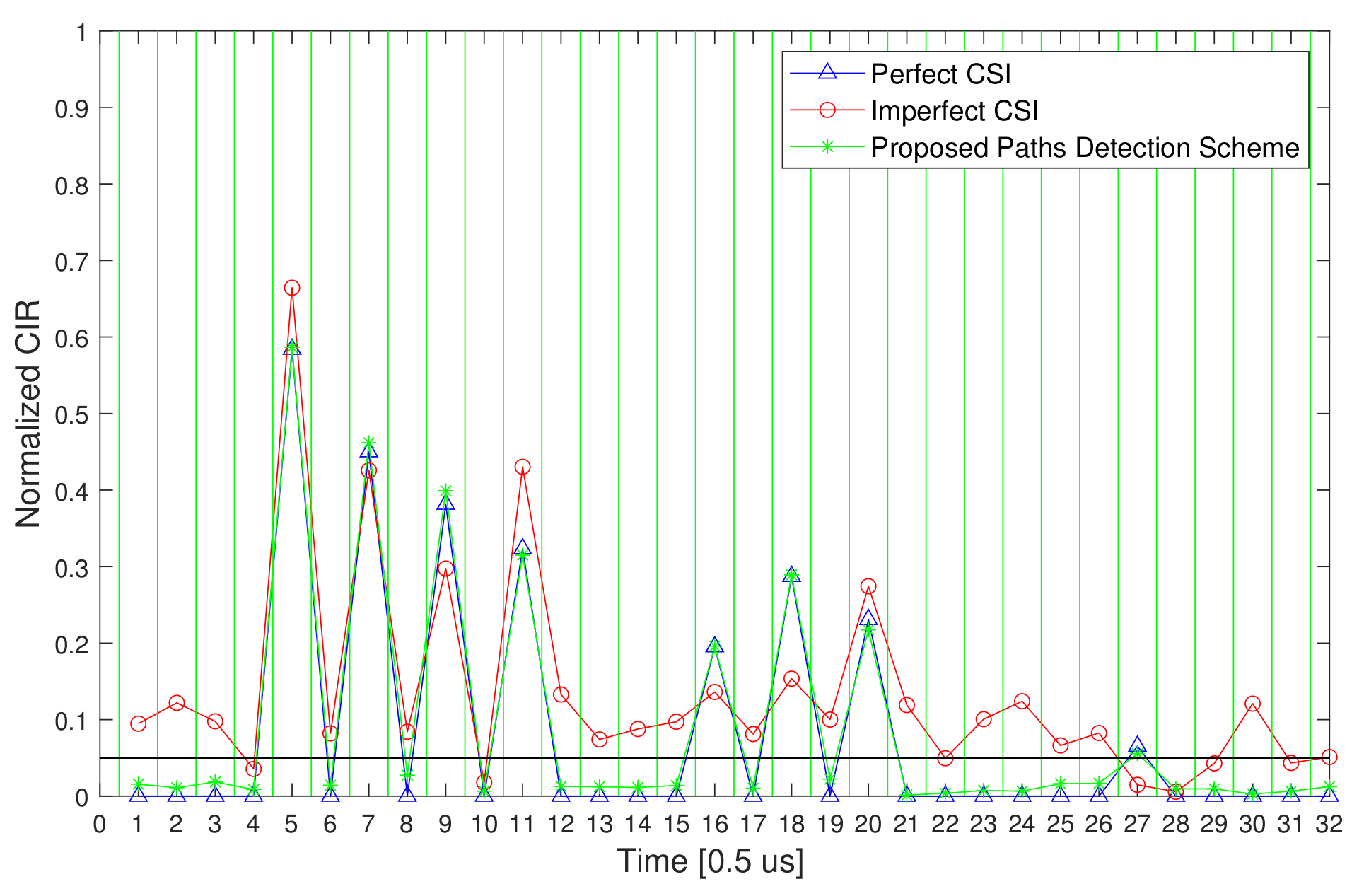
  • Step 1: Consisting of a channel probing, using initial signaling and synchronization between the corresponding nodes of the considered link. In particular, by using N O b s received signals, the relevant CIRs h ^ ( n ) , n { 1 , . . N O b s } should be estimated. While node access control is outside the scope of this contribution, we assume that all legitimate nodes are registered and synchronized in the considered local network to accurately estimate the corresponding CIRs.
  • Step 2: In this Step, the channel estimation error can be reduced by averaging the N O b s estimated CIRs. This error minimization is crucial to offer accurate PL ID as well as to increase the received SNR, and hence to improve the data transmission quality in general.
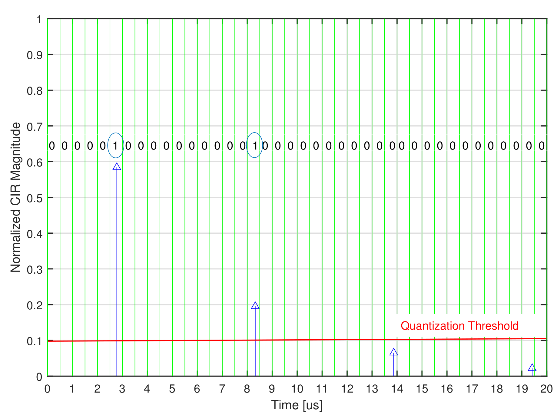
  • Step 3: A standard quantization can be used in this final Step to generate the PL ID.
Figure 8, Figure 9, Figure 10 and Figure 11, show the corresponding normalized CIR magnitudes for the four scenarios previously presented.
Algorithm 1 PL Identification Scheme.
1:
Inputs: PL ID Length: I D L e n
2:
        Sampling Time: T S
3:
        Quantization Threshold
4:
        Number of observations: N O b s
5:
        Received Signals: y ( n ) , n { 1 , . . N O b s }
6:
Step 1: Channel Probing
7:
        Estimation of the different N O b s CIRs: h ^ ( n )
8:
Step 2: Minimizing the Channel Estimation Error:
9:
           h ˜ = n = 1 N O b s h ^ ( n ) N O b s
10:
Step 3: CIR quantization to generate the PL ID.

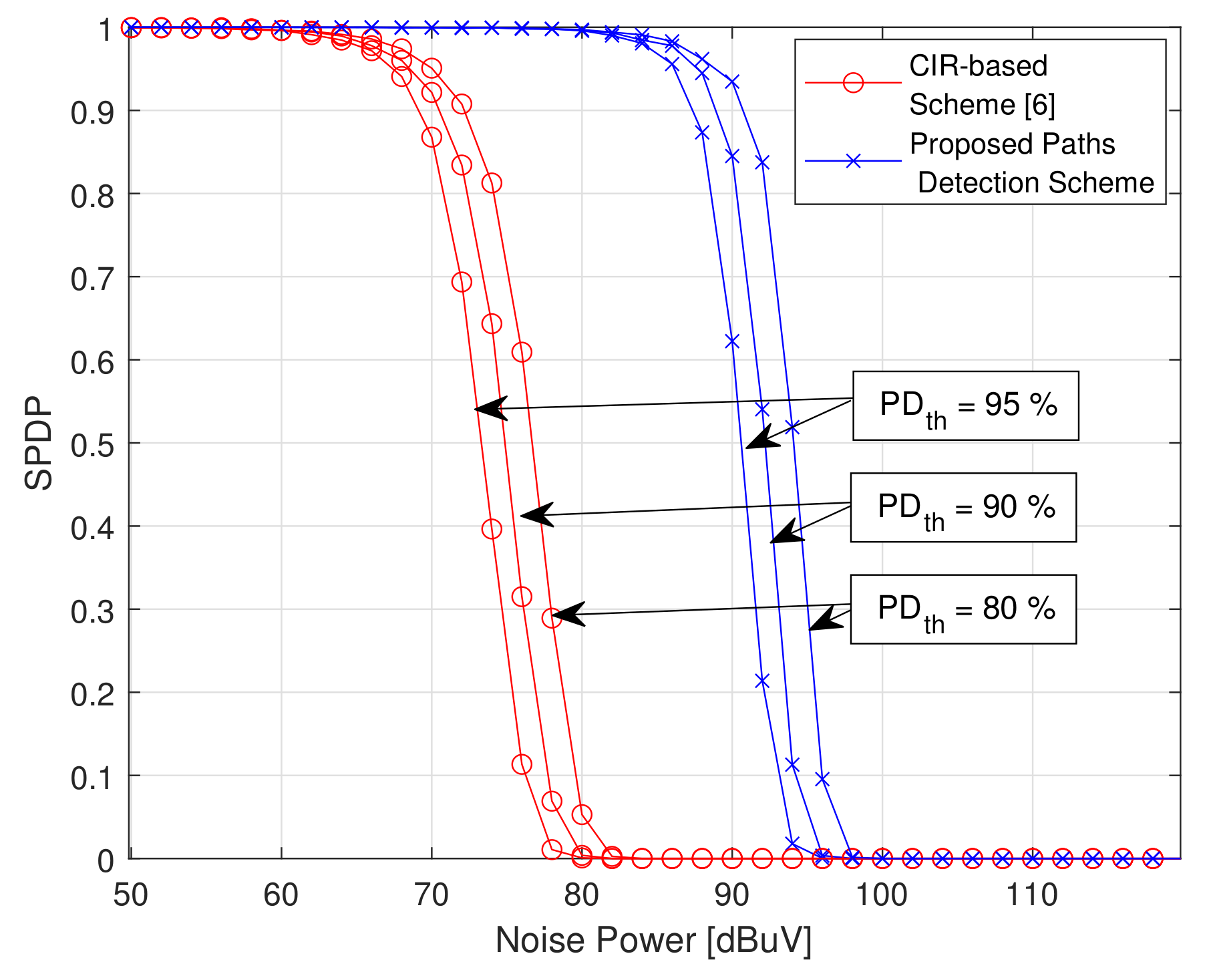
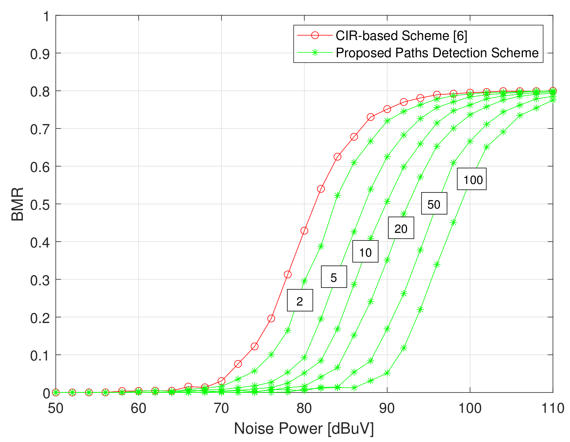
5. Simulation Results and Discussion

Without loss of generality, we have considered Scenario 4 of Figure 7d, presented in Section 3.2, to evaluate the numerical results and advantages of the proposed power line identification scheme and its potential application. The simulations were carried out in Matlab R2022a, with the following parameters: L A B = 416 , L A C = 100 m, L C B = 316 m, L C D = 170 m, L C E = 300 m, L B F = 70 m, α = 30 dB/m, ρ X = 20 dB, δ X = 10 dB, T S = 0.5 us, the PL ID length = 32 , and the average PLC noise range from 50 dBuV to 110 dBuV [14,51,52,53]. Figure 12 presents the normalized CIR for the proposed scheme, as well as the perfect and imperfect normalized CIRs. The cited figure shows that the proposal outputs almost the same result as that of a perfect CIR, which yields an accurate CIR estimation, and hence an accurate PL ID.
To assess the performance and the accuracy of the proposed scheme, we present in Figure 13 a comparison of the successful path detection probability (SPDP) between the proposed scheme and the related work in [6] that represents the most relevant technique in the literature. In particular, the cited authors have introduced a CIR quantization for PLS Key generation. We follow a similar approach, enhancing the CSI accuracy to provide PL link identifications. We will refer to the cited solution as PT scheme (from the surnames of the authors: Passerini and Tonello).
The SPDP is defined as the probability that the number of detected paths is larger than or equal to a given path detection threshold (PD th ). As shown in the cited figure, the SPDP of the proposed scheme is higher than that of the PT scheme for all the different path detection thresholds. As expected, the SPDP increases when PD th decreases. In addition, the figure shows that an average gain (in terms of noise power) of more than 15 dB can be reached by using the proposed scheme to offer the same SPDP as the PT scheme. In fact, for a given SPDP, e.g., 0.9, and a given PD th = 90 % , the PT scheme can offer the target SPDP when the noise power is equal to or less than 71 dBuV. However, the proposed scheme is able to offer the same SPDP, when the noise power is equal to or less than 89 dBuV, with a noise power gain of 18 dB. These results confirm the robustness and the accuracy of the proposed scheme, even for noisy PLC environments.
In Figure 14, we present the Successful Path Detection Gain (SPDG) trade-off between our proposal and the PT scheme for different values of the transmission delay. The SPDG is defined as the difference between the proposal’s successful path detection probabilities and the PT scheme in percentage units. For the transmission delay, and without loss of generality, we have considered the OFDM symbol duration within PRIME technology, which is equal to 2.048 ms [54]. In accordance with the proposed scheme, for a given number of observations ( N O b s ), the same number of OFDM symbols is needed to estimate and conduct the N O b s CIRs average. Consequently, a delay of N O b s times the considered OFDM symbol duration can be observed. For the conducted simulations, different observation values are used, e.g., N O b s = { 2 , 5 , 10 , 20 , 50 , 100 } , and hence the different corresponding transmission delays, 4.09 , 10.24 , 20.48 , 40.96 , 102.4 , and 204.8 ms, are presented. As shown in the cited figure, for the different observation numbers/transmission delays, when increasing the noise power the SPDG increases until it reaches a given maximum, then it decreases and converges to a null value. To explain the observed behavior, let us define the noise power efficient range as the range of noise power, between N P m i n and N P m a x , where the proposed scheme offers better performance than the PT scheme in terms of SPDP. For a noise power level less than N P m i n , the noise effect on the channel estimation accuracy is negligible for both schemes—the SPDP having reached the value 1 for both cases, as shown in Figure 13. In this case, no gain in terms of successful path detection can be observed—the SPDG is null. However, by increasing the noise power, with values larger than N P m i n , our proposal outperforms the PT scheme, as the increase in the SPDG shows. This is due to the fact that the proposal provides a better reduction in the channel estimation error when compared to the case of the PT scheme. Then, by further increasing the noise power, the gain of the proposed scheme with respect to the PT scheme is progressively reduced, reaching the value zero. This is because a higher noise power value significantly affects the accuracy of both schemes in terms of SPDP, which reaches zero for both schemes for noise power larger than or equal to N P m a x . Hence, no difference between the performance of the two schemes can be observed in this case due to the significant signal-to-noise ratio (SNR) degradation. In addition, the cited figure shows that the noise power efficient range and maximum SPDG increase with the increased number of observations, which is expected. On the other hand, using a large number of observations, the solution enhances the accuracy of the estimated CIR, by reducing the channel estimation error, yielding a significant gain with respect to the PT scheme. On the another hand, increasing the number of observations results in a transmission delay. However, this delay can be ignored, as the potential applications of the proposed scheme generally do not require a real-time response. Moreover, the cited delays are in the order of ms. As an example, in Figure 14, it can be noted that, for a transmission delay of only 204.8 ms, a noise power efficient range of 30 dB with a successful path detection gain of more than 90% can be observed.
In Figure 15, we present the variation in the bit mismatch rate (BMR) vs. the noise power for different numbers of observations: 2 , 5 , 10 , 20 , 50 , and 100. In this work, the BMR is defined as the difference ratio in terms of bits between the PL ID, given by the proposed scheme, and that given by the perfect CSI. As shown in the cited figure, by increasing the number of observations, we can easily reduce the CIR errors and hence the BMR. This is because, as explained for Algorithm 1, by increasing the number of observations, the average channel estimation error decreases, and hence a reduction in the channel estimation error can be observed. Additionally, it is shown that the BMR increases in response to noise and achieves its maximum of 0.8 for this particular scenario. This limit is the result of the effect of saturation in the generated PL ID in combination with the fixed parameter of 20 % of bits of ones used in the simulation.

6. Conclusions

In this paper, we have proposed a PLC physical layer identification scheme that is effective even under imperfect channel state information conditions. The solution reduces the CIR estimation error produced by the noise affecting a power line, hence offering a highly successful path detection probability. The results show an accurate physical layer identification of the links connecting the PLC nodes in the network, even under high noise levels. In particular, with respect to similar solutions using CIR quantization, the proposal enjoys a path detection gain of more than 80 % when the noise power ranges between 80 dBuV and 90 dBuV. For noise levels below 80 dBuV our solution provides 100 % accuracy. This significant improvement in the path detection ability can enable multiple applications that take advantage of the information provided by the PLC signals. Moreover, to the best of our knowledge, the proposed scheme is the first one that tackles the PLC channel estimation error to provide an accurate physical layer identification scheme under the assumption of an imperfect CSI. Finally, other than being interesting on its own, the proposed contribution could also pave the way to further research and applications in the PLC domain.

Author Contributions

Conceptualization, J.H.F. and R.D.P.; data curation, J.H.F. and A.O.; formal analysis, A.O.; investigation, J.H.F. and A.O.; methodology, J.H.F. and R.D.P.; software, J.H.F.; supervision, R.D.P.; validation, A.O. and R.D.P.; writing—original draft, J.H.F.; writing—review and editing, J.H.F., A.O. and R.D.P. All authors have read and agreed to the published version of the manuscript.

Funding

This research received no external funding.

Institutional Review Board Statement

Not applicable.

Informed Consent Statement

Not applicable.

Data Availability Statement

Not applicable.

Acknowledgments

This publication is supported by Iberdrola S.A. as part of its innovation department research studies. Its contents are solely the responsibility of the authors and do not necessarily represent the official views of Iberdrola Group.

Conflicts of Interest

The authors declare no conflict of interest.

References

  1. Uribe-Pérez, N.; Hernández, L.; la Vega, D.D.; Angulo, I. State of the Art and Trends Review of Smart Metering in Electricity Grids. Appl. Sci. 2016, 6, 68. [Google Scholar] [CrossRef]
  2. Cano, C.; Pittolo, A.; Malone, D.; Lampe, L.; Tonello, A.M.; Dabak, A.G. State of the Art in Power Line Communications: From the Applications to the Medium. IEEE J. Sel. Areas Commun. 2016, 34, 1935–1952. [Google Scholar] [CrossRef] [Green Version]
  3. Sharma, K.; Saini, L.M. Power-line Communications for Smart Grid: Progress, Challenges, Opportunities and Status. Renew. Sustain. Energy Rev. 2017, 67, 704–751. [Google Scholar] [CrossRef]
  4. Zhang, J.; Duong, T.Q.; Marshall, A.; Woods, R. Key Generation From Wireless Channels: A Review. IEEE Access 2016, 4, 614–626. [Google Scholar] [CrossRef] [Green Version]
  5. Wang, T.; Liu, Y.; Athanasios, A. Survey on Channel Reciprocity based Key Establishment Techniques for Wireless Systems. Wirel. Netw. 2015, 21, 1835–1846. [Google Scholar] [CrossRef]
  6. Passerini, F.; Tonello, A.M. Secure PHY Layer Key Generation in the Asymmetric Power Line Communication Channel. Electronics 2020, 9, 605. [Google Scholar] [CrossRef] [Green Version]
  7. Yaacoub, J.P.A.; Hernandez Fernandez, J.; Noura, H.N.; Chehab, A. Security of Power Line Communication systems: Issues, limitations and existing solutions. Comput. Sci. Rev. 2021, 39, 100331. [Google Scholar] [CrossRef]
  8. Lampe, L.; Tonello, A.M.; Swart, T.G. Power Line Communications: Principles, Standards and Applications from Multimedia to Smart Grid; John Wiley & Sons: Hoboken, NJ, USA, 2016. [Google Scholar]
  9. De Piante, M.; Tonello, A.M. Characteristics of the PLC channel: Reciprocity, symmetry and port decoupling for impedance matching. In Proceedings of the 2016 International Symposium on Power Line Communications and its Applications (ISPLC), Bottrop, Germany, 20–23 March 2016; pp. 93–97. [Google Scholar]
  10. Hussain, S.; Fernandez, J.H.; Al-Ali, A.K.; Shikfa, A. Vulnerabilities and Countermeasures in Electrical Substations. Int. J. Crit. Infrastruct. Prot. 2021, 33, 100406. [Google Scholar] [CrossRef]
  11. Radoglou-Grammatikis, P.I.; Sarigiannidis, P.G. Securing the Smart Grid: A Comprehensive Compilation of Intrusion Detection and Prevention Systems. IEEE Access 2019, 7, 46595–46620. [Google Scholar] [CrossRef]
  12. Sendin, A.; Peña, I.; Angueira, P. Strategies for Power Line Communications Smart Metering Network Deployment. Energies 2014, 7, 2377–2420. [Google Scholar] [CrossRef] [Green Version]
  13. Noura, H.N.; Melki, R.; Chehab, A.; Hernandez Fernandez, J. Efficient and Robust Data Availability Solution for Hybrid PLC/RF Systems. Comput. Netw. 2021, 185, 107675. [Google Scholar] [CrossRef]
  14. Omri, A.; Hernandez Fernandez, J.; Sanz, A.; Fliss, M.R. PLC Channel Selection Schemes for OFDM-based NB-PLC Systems. In Proceedings of the 2020 IEEE International Symposium on Power Line Communications and its Applications (ISPLC), Malaga, Spain, 11–13 May 2020; pp. 1–6. [Google Scholar]
  15. Vlasa, I.; Gligor, A.; Dumitru, C.D.; Iantovics, L.B. Smart Metering Systems Optimization for Non-Technical Losses Reduction and Consumption Recording Operation Improvement in Electricity Sector. Sensors 2020, 20, 2947. [Google Scholar] [CrossRef]
  16. Patel, K.B.; Kumar, A.A.; Ghatak, A.; Borole, S.; Pandit, T. Design and Implementation of Modular Smart Meter Device to Detect and Locate Power Theft using PLC Communication. In Proceedings of the 2020 International Conference on Smart Electronics and Communication (ICOSEC), Trichy, India, 10–12 September 2020; pp. 547–552. [Google Scholar]
  17. Bin-Halabi, A.; Nouh, A.; Abouelela, M. Remote Detection and Identification of Illegal Consumers in Power Grids. IEEE Access 2019, 7, 71529–71540. [Google Scholar] [CrossRef]
  18. Lisowski, M.; Masnicki, R.; Mindykowski, J. PLC-Enabled Low Voltage Distribution Network Topology Monitoring. IEEE Trans. Smart Grid 2019, 10, 6436–6448. [Google Scholar] [CrossRef]
  19. Uribe-Pérez, N.; Hernández, L.; Gómez, R.; Soria, S.; de la Vega, D.; Angulo, I.; Arzuaga, T.; Gutiérrez, L. Smart management of a distributed generation microgrid through PLC PRIME technology. In Proceedings of the 2015 International Symposium on Smart Electric Distribution Systems and Technologies (EDST), Vienna, Austria, 8–11 September 2015; pp. 374–379. [Google Scholar]
  20. Caprolu, M.; Hernandez Fernandez, J.; Alassi, A.; Di Pietro, R. Increasing Renewable Generation Feed-In Capacity Leveraging Smart Meters. In Proceedings of the 2020 IEEE Green Energy and Smart Systems Conference (IGESSC), Long Beach, CA, USA, 2–3 November 2020; pp. 1–7. [Google Scholar]
  21. Christopher, A.V.; Swaminathan, G.; Subramanian, M.; Thangaraj, P. Distribution Line Monitoring System for the Detection of Power Theft Using Power Line Communication. In Proceedings of the 2014 IEEE Conference on Energy Conversion (CENCON), Johor Bahru, Malaysia, 13–14 October 2014; pp. 55–60. [Google Scholar]
  22. Cho, M.; Huang, H.; Chen, C.; Thom, H.T.; Wang, P.; Chang, W.; Wang, C. The Implementation and Applications of Low Voltage Distribution Line Theft Supervisory System. In Proceedings of the 2016 3rd International Conference on Green Technology and Sustainable Development (GTSD), Kaohsiung, Taiwan, 24–25 November 2016; pp. 178–184. [Google Scholar]
  23. Moreno, J.A.; Quintanilla, R. Smart Grid Applications Using Narrow Band Power Line Carrier in Underground Power Distribution Systems. PLC Fault Locator. In Proceedings of the CIRED 2009—20th International Conference and Exhibition on Electricity Distribution—Part 1, Prague, Czech Republic, 8–11 June 2009; pp. 1–4. [Google Scholar]
  24. Zhao, X.; Qi, Y.; Li, G. Research and Implementation of PLC for Multiport Traveling Wave Fault Location in the Medium Voltage Distribution Network. In Proceedings of the 2011 4th International Conference on Electric Utility Deregulation and Restructuring and Power Technologies (DRPT), Weihai, China, 6–9 July 2011; pp. 614–617. [Google Scholar]
  25. Passerini, F.; Tonello, A.M. Smart Grid Monitoring Using Power Line Modems: Anomaly Detection and Localization. IEEE Trans. Smart Grid 2019, 10, 6178–6186. [Google Scholar] [CrossRef] [Green Version]
  26. Prasad, G.; Huo, Y.; Lampe, L.; Leung, V.C.M. Machine Learning Based Physical-Layer Intrusion Detection and Location for the Smart Grid. In Proceedings of the 2019 IEEE International Conference on Communications, Control, and Computing Technologies for Smart Grids (SmartGridComm), Beijing, China, 21–23 October 2019; pp. 1–6. [Google Scholar]
  27. Smail, M.K.; Pichon, L.; Olivas, M.; Auzanneau, F.; Lambert, M. Recent Progress in EMC and Reliability for Automotive Applications. In Proceedings of the VXV International Symposium on Theoretical Engineering, Lübeck, Germany, 22–24 June 2009; pp. 1–5. [Google Scholar]
  28. Smail, M.K.; Pichon, L.; Olivas, M.; Auzanneau, F.; Lambert, M. Detection of Defects in Wiring Networks Using Time Domain Reflectometry. IEEE Trans. Magn. 2010, 46, 2998–3001. [Google Scholar] [CrossRef] [Green Version]
  29. Ahmed, M.O.; Lampe, L. Power Line Communications for Low-Voltage Power Grid Tomography. IEEE Trans. Commun. 2013, 61, 5163–5175. [Google Scholar] [CrossRef]
  30. Erseghe, T.; Tomasin, S.; Vigato, A. Topology Estimation for Smart Micro Grids via Powerline Communications. IEEE Trans. Signal Process. 2013, 61, 3368–3377. [Google Scholar] [CrossRef]
  31. Zhang, C.; Zhu, X.; Huang, Y.; Liu, G. High-Resolution and Low-Complexity Dynamic Topology Estimation for PLC Networks Assisted by Impulsive Noise Source Detection. IET Commun. 2016, 10, 443–451. [Google Scholar] [CrossRef]
  32. Ulrich, M.; Yang, B. Inference of Wired Network Topology Using Multipoint Reflectometry. In Proceedings of the 2015 23rd European Signal Processing Conference (EUSIPCO), Nice, France, 31 August–4 September 2015; pp. 1920–1924. [Google Scholar]
  33. Rohling, H. Radar CFAR Thresholding in Clutter and Multiple Target Situations. IEEE Trans. Aerosp. Electron. Syst. 1983, AES-19, 608–621. [Google Scholar] [CrossRef]
  34. Aouichak, I.; Khalil, K.; Elfeki, I.; Le Bunetel, J.; Raingeaud, Y. Topology Identification Method for Unknown Indoor PLC Home Networks. In Proceedings of the 2017 International Symposium on Electromagnetic Compatibility—EMC EUROPE, Angers, France, 4–7 September 2017; pp. 1–4. [Google Scholar]
  35. Lee, K.; Klingensmith, N.; Banerjee, S.; Kim, Y. VoltKey: Continuous Secret Key Generation Based on Power Line Noise for Zero-Involvement Pairing and Authentication. Proc. ACM Interact. Mobile Wearable Ubiquitous Technol. 2019, 3, 1–26. [Google Scholar] [CrossRef]
  36. Ahmed, M.O.; Lampe, L. Parametric and Non Parametric Methods for Power Line Network Topology Tnference. In Proceedings of the 2012 IEEE International Symposium on Power Line Communications and Its Applications, Beijing, China, 27–30 March 2012; pp. 274–279. [Google Scholar]
  37. Henkel, W.; Graur, O.A.; Islam, N.S.; Pagel, U.; Manak, N.; Can, O. Reciprocity for Physical Layer Security with Wireless FDD and in Wireline Communications. In Proceedings of the 2018 IEEE Globecom Workshops (GC Wkshps), Abu Dhabi, United Arab Emirates, 9–13 December 2018; pp. 1–6. [Google Scholar]
  38. Henkel, W.; Turjman, A.M.; Kim, H.; Qanadilo, H.K.H. Common Randomness for Physical-Layer Key Generation in Power-Line Transmission. In Proceedings of the ICC 2020—2020 IEEE International Conference on Communications (ICC), Dublin, Ireland, 7–11 June 2020; pp. 1–6. [Google Scholar]
  39. Yang, F.; Islam, M.A.; Ren, S. PowerKey: Generating Secret Keys from Power Line Electromagnetic Interferences. In International Conference on Network and System Security; Springer: Cham, Switzerland, 2020; pp. 354–370. [Google Scholar]
  40. Ahmed, M.O.; Lampe, L. Power Line Network Topology Inference Using Frequency Domain Reflectometry. In Proceedings of the 2012 IEEE International Conference on Communications (ICC), Ottawa, ON, Canada, 10–15 June 2012; pp. 3419–3423. [Google Scholar]
  41. Lampe, L.; Ahmed, M.O. Power Grid Topology Inference Using Power Line Communications. In Proceedings of the 2013 IEEE International Conference on Smart Grid Communications (SmartGridComm), Vancouver, BC, Canada, 21–24 October 2013; pp. 336–341. [Google Scholar]
  42. Passerini, F.; Tonello, A.M. Smart Grid Monitoring Using Power Line Modems: Effect of Anomalies on Signal Propagation. IEEE Access 2019, 7, 27302–27312. [Google Scholar] [CrossRef]
  43. Maenou, T.; Katayama, M. Study on Signal Attenuation Characteristics in Power Line Communications. In Proceedings of the 2006 IEEE International Symposium on Power Line Communications and Its Applications, Orlando, FL, USA, 26–29 March 2006; pp. 217–221. [Google Scholar]
  44. Çelebi, H.B. Noise and Multipath Characteristics of Power Line Communication Channels. Ph.D. Thesis, University of South Florida, Tampa, FL, USA, 2010. [Google Scholar]
  45. Güzelgöz, S.; Çelebi, H.B.; Güzel, T.; Arslan, H.; Mıhçak, M.K. Time Frequency Analysis of Noise Generated by Electrical Loads in PLC. In Proceedings of the 2010 17th International Conference on Telecommunications, Doha, Qatar, 4–7 April 2010; pp. 864–871. [Google Scholar]
  46. Güzelgöz, S.; Çelebi, H.B.; Arslan, H. Statistical Characterization of the Paths in Multipath PLC Channels. IEEE Trans. Power Deliv. 2011, 26, 181–187. [Google Scholar] [CrossRef]
  47. Çelebi, H.B.; Güzelgöz, S.; Güzel, T.; Arslan, H. Noise and Channel Statistics of Indoor Power Line Networks. In Proceedings of the 2011 18th International Conference on Telecommunications, Ayia Napa, Cyprus, 8–11 May 2011; pp. 523–527. [Google Scholar]
  48. Güzelgöz, S.; Celebi, H.B.; Arslan, H. Articulating Factors Defining RMS Delay Spread in LV PLC Networks. J. Comput. Syst. Networks, Commun. 2010, 2010. [Google Scholar] [CrossRef]
  49. Sánchez-Martínez, J.J.; Cortés, J.A.; Díez, L.; Cañete, F.J.; Torres, L.M. Performance Analysis of OFDM Modulation on Indoor PLC Channels in the Frequency Band up to 210 MHz. In Proceedings of the ISPLC2010, Rio de Janeiro, Brazil, 28–31 March 2010; pp. 38–43. [Google Scholar]
  50. Yonge, L.; Abad, J.; Afkhamie, K.; Guerrieri, L.; Katar, S.; Lioe, H.; Riva, R.; Schneider, D.; Schwager, A. An Overview of the HomePlug AV2 Technology. J. Electr. Comput. Eng. 2013, 2013. [Google Scholar] [CrossRef]
  51. Raponi, S.; Fernandez, J.H.; Omri, A.; Oligeri, G. Long-Term Noise Characterization of Narrowband Power Line Communications. IEEE Trans. Power Deliv. 2022, 37, 365–373. [Google Scholar] [CrossRef]
  52. Fliss, M.R.; Hernandez Fernandez, J.; Omri, A.; Oligeri, G. NB-PLC Successful Transmission Probability Analysis. In Proceedings of the 2019 2nd International Conference on Smart Grid and Renewable Energy (SGRE), Doha, Qatar, 19–21 November 2019; pp. 1–6. [Google Scholar]
  53. Fernandez, J.H.; Lacasa, L.; Omri, A.; Sanz, A.; Koborsi, M.E. Ergodic Capacity Analysis of OFDM-based NB-PLC Systems. In Proceedings of the 2022 24th International Conference on Advanced Communication Technology (ICACT), PyeongChang Kwangwoon Do, Korea, 13–16 February 2022; pp. 399–405. [Google Scholar]
  54. PRIME Alliance Technical Working Group. Specification for PoweRline Intelligent Metering Evolution, R1.4 2014. Available online: https://www.prime-alliance.org/wp-content/uploads/2021/12/PRIME-Spec_v1.420210914.pdf (accessed on 2 May 2022).
Figure 1. Example of a power line communication (PLC) channel frequency response estimation (CFRe) in both directions and in the frequency (a) and time (b) domain.
Energies 15 06055 g001
Figure 2. CIR of the link between two given communicating devices, A and B, in a T network with a termination point D.
Energies 15 06055 g002
Figure 3. CIR for (a) increase and (b) decrease in distance between the transmitter and receiver.
Energies 15 06055 g003
Figure 4. Response of path delay impulses for (a) increase and (b) decrease in the branch length.
Energies 15 06055 g004
Figure 5. Response of path delay impulses with the increase in branching points.
Energies 15 06055 g005
Figure 6. A Simple daisy chain connection with three nodes.
Energies 15 06055 g006
Figure 7. PL System connection scenarios: (a) Scenario 1, (b) Scenario 2, (c) Scenario 3, and (d) Scenario 4.
Energies 15 06055 g007
Figure 8. CIR of Scenario 1.
Energies 15 06055 g008
Figure 9. CIR of Scenario 2.
Energies 15 06055 g009
Figure 10. CIR of Scenario 3.
Energies 15 06055 g010
Figure 11. CIR of Scenario 4.
Energies 15 06055 g011
Figure 12. CIR variation in the proposed scheme, as well as for the perfect and imperfect CSIs.
Energies 15 06055 g012
Figure 13. Comparison of the SPDP for the proposed scheme and the PT scheme vs. noise power, for N obs = 100 , and for different values of path detection threshold (PD th ).
Energies 15 06055 g013
Figure 14. Successful path detection gain (SPDG) vs. transmission delay, with respect to the PT scheme.
Energies 15 06055 g014
Figure 15. BMR variations for the proposed scheme and the PT scheme, with different number of observations: 2 , 5 , 10 , 20 , 50 , and 100.
Energies 15 06055 g015
Table 1. PLC Signal-based Solutions.
Processing DomainRef.TechniqueApplicationsEnvironmentCSIINLimitations
Time[27,28]Single-Point ReflectometryGrid DiagnosisAutomotiveNCNC- A high-frequency sampling is needed.
- Short PL application only.
[30]ToA-based Two-Way HandshakeTopology EstimationLVNCNC- A device at every node is required.
[32]Multi-Point Reflectometry and OS-CFAR Detector [33]Topology Estimation.GeneralNCNC (G)- Reflection measurements at multiple cable ends.
- A high implementation complexity.
[34]ToATopology EstimationIndoorNCNC- Multiple measurements are needed at each end point of the topology.
[6]CIR-based PLS Key GenerationPLC SecurityGeneralImperfect KnownC- The channel estimation error is ignored.
[35]PL Noise-based Key GenerationIoT Devices Pairing and Authentication.IndoorNCC- The malicious devices cannot be avoided.
[36]Single-Point ReflectometryTopology EstimationLVPerfect KnownNC- Attenuated received signals due to long PL lengths and branching.
Frequency[6]Tx Matrix Estimation-based PLS Key Generation.PLC SecurityGeneralImperfect KnownC- A device at each point is needed to estimate Tx Matrix.
[37]- CFR-based PLS Key Generation
- FEXT Function-based PLS Key Generation
PLC SecurityGeneralPerfect KnownC- A High CFR symmetry assumption.
[38]CFR-based Random PLS Key GenerationPLC SecurityGeneralPerfect KnownC- A High CFR symmetry assumption.
[39]EMI-based PLS Key GenerationPLC SecurityIndoorNCC- The devices must be close to each other to observe the same noise patterns.
[36,40]Single-Point ReflectometryTopology Estimation and Grid DiagnosticsLVPerfect KnownNC- Significant effects of the signal attenuation.
- A high implementation complexity.
Time-Freq.[29,41]ToATopology Estimation, PLC routing and Grid DiagnosisLVPerfect KnownNC- The impact of impulsive noise is not considered.
[31]- Single-Point Reflectometry
- Node-by-node greedy algorithm
Topology EstimationIndoorperfect KnownC- The proposed technique assumes a perfect known of CSI.
[42]- Multi-Point Reflectometry
- ToA
Topology Estimation Grid DiagnosticsGeneralPerfect KnownNC- The impact of impulsive noise is not considered.
- A significant signal attenuation impact on the result accuracy.
[25]- Single-Point Reflectometry
- Multi-Point Reflectometry
- ToA.
Grid DiagnosticsGeneralImperfect KnownC- The channel estimation error is ignored.
C: Considered, NC: Not Considered, G: Gaussian.
Table 2. Power delay profiles of the ( N = 10 ) first arrived paths for the different scenarios.
#Path TypePath Index l i g i
1A-B-i(B-A-B) i [ 0 , 10 ] L A B ( 1 + 2 i ) ( 1 α L A B ) 2 i + 1 ( 1 ρ A ) i ( 1 ρ B ) i
2A-C-B i = 0 L A B ( 1 α L A C ) ( 1 α L C B ) ( 1 δ C )
A-C-A-C-B i = 1 3 L A C + L C B ( 1 α L A C ) 3 ( 1 α L C B ) ( 1 ρ A ) ( 1 ρ C ) ( 1 δ C )
A-C-D-C-B i = 2 L A C + 2 L C D + L C B ( 1 α L A C ) ( 1 α L C D ) 2 ( 1 α L C B ) ( 1 ρ D ) ( 1 δ C ) 2
A-C-A-C-A-C-B i = 3 5 L A C + L C B ( 1 α L A C ) 5 ( 1 α L C B ) ( 1 ρ A ) 2 ( 1 ρ C ) 2 ( 1 δ C )
A-C-D-C-A-C-B i = 4 3 L A C + 2 L C D + L C B ( 1 α L A C ) 3 ( 1 α L C D ) 2 ( 1 α L C B ) ( 1 ρ A ) ( 1 ρ D ) ( 1 δ C ) 3
A-C-A-C-D-C-B i = 5 3 L A C + 2 L C D + L C B ( 1 α L A C ) 3 ( 1 α L C D ) 2 ( 1 α L C B ) ( 1 ρ A ) ( 1 ρ C ) ( 1 ρ D ) ( 1 δ C ) 2
A-C-B-C-B i = 6 L A C + 3 L C B ( 1 α L A C ) ( 1 α L C B ) 3 ( 1 ρ B ) ( 1 ρ C ) ( 1 δ C )
A-C-D-C-D-C-B i = 7 L A C + 4 L C D + L C B ( 1 α L A C ) ( 1 α L C D ) 4 ( 1 α L C B ) ( 1 ρ C ) ( 1 ρ D ) 2 ( 1 δ C ) 2
A-C-A-C-B-C-B i = 8 3 L A C + 3 L C B ( 1 α L A C ) 3 ( 1 α L C B ) 3 ( 1 ρ A ) ( 1 ρ B ) ( 1 ρ C ) 2 ( 1 δ C )
A-C-B-C-A-C-B i = 9 3 L A C + 3 L C B ( 1 α L A C ) 3 ( 1 α L C B ) 3 ( 1 ρ A ) ( 1 ρ B ) ( 1 δ C ) 3
3A-C-B i = 0 L A B ( 1 α L A C ) ( 1 α L C B ) ( 1 δ C )
A-C-A-C-B i = 1 3 L A C + L C B ( 1 α L A C ) 3 ( 1 α L C B ) ( 1 ρ A ) ( 1 ρ C ) ( 1 δ C )
A-C-D-C-B i = 2 L A C + 2 L C D + L C B ( 1 α L A C ) ( 1 α L C D ) 2 ( 1 α L C B ) ( 1 ρ D ) ( 1 δ C ) 2
A-C-A-C-A-C-B i = 3 5 L A C + L C B ( 1 α L A C ) 5 ( 1 α L C B ) ( 1 ρ A ) 2 ( 1 ρ C ) 2 ( 1 δ C )
A-C-D-C-A-C-B i = 4 3 L A C + 2 L C D + L C B ( 1 α L A C ) 3 ( 1 α L C D ) 2 ( 1 α L C B ) ( 1 ρ A ) ( 1 ρ D ) ( 1 δ C ) 3
A-C-A-C-D-C-B i = 5 3 L A C + 2 L C D + L C B ( 1 α L A C ) 3 ( 1 α L C D ) 2 ( 1 α L C B ) ( 1 ρ A ) ( 1 ρ C ) ( 1 ρ D ) ( 1 δ C ) 2
A-C-B-C-B i = 6 L A C + 3 L C B ( 1 α L A C ) ( 1 α L C B ) 3 ( 1 ρ B ) ( 1 ρ C ) ( 1 δ C )
A-C-D-C-D-C-B i = 7 L A C + 4 L C D + L C B ( 1 α L A C ) ( 1 α L C D ) 4 ( 1 α L C B ) ( 1 ρ C ) ( 1 ρ D ) 2 ( 1 δ C ) 2
A-C-A-C-E-C-B i = 8 3 L A C + 2 L C E + L C B ( 1 α L A C ) 3 ( 1 α L C E ) 2 ( 1 α L C B ) ( 1 ρ A ) ( 1 ρ C ) ( 1 ρ E ) ( 1 δ C ) 2
A-C-E-C-E-C-B i = 9 L A C + 4 L C E + L C B ( 1 α L A C ) ( 1 α L C E ) 4 ( 1 α L C B ) ( 1 ρ C ) ( 1 ρ E ) 2 ( 1 δ C ) 2
4A-B i = 0 L A B ( 1 α L A B )
A-B-F-B i = 1 L A B + 2 L B F ( 1 α L A B ) ( 1 α L B F ) 2 ( 1 ρ F ) ( 1 δ B )
A-B-F-B-F-B i = 2 L A B + 4 L B F ( 1 α L A B ) ( 1 α L B F ) 4 ( 1 ρ B ) ( 1 ρ F ) 2 ( 1 δ B )
A-B-F-B-F-B-F-B i = 3 L A B + 6 . L A B ( 1 α L A B ) ( 1 α L B F ) 6 ( 1 ρ B ) 2 ( 1 ρ F ) 3 ( 1 δ B )
A-B-A-B i = 4 3 L A B ( 1 α L A B ) 3 ( 1 ρ A ) ( 1 ρ B )
A-B-A-B-F-B i = 5 3 L A B + 2 L B F ( 1 α L A B ) 3 ( 1 α L B F ) 2 ( 1 ρ A ) ( 1 ρ B ) ( 1 ρ F ) ( 1 δ B )
A-B-F-B-A-B i = 6 3 L A B + 2 L B F ( 1 α L A B ) 3 ( 1 α L B F ) 2 ( 1 ρ A ) ( 1 ρ F ) 2 ( 1 δ B ) 2
A-B-F-B-A-B-F-B i = 7 3 L A B + 4 L B F ( 1 α L A B ) 3 ( 1 α L B F ) 4 ( 1 ρ A ) ( 1 ρ F ) 2 ( 1 δ B ) 3
A-B-A-B-F-B-F-B i = 8 3 L A B + 4 L B F ( 1 α L A B ) 3 ( 1 α L B F ) 4 ( 1 ρ A ) ( 1 ρ B ) 2 ( 1 ρ F ) 2 ( 1 δ B )
A-B-A-B-A-B i = 9 5 L A B ( 1 α L A B ) 5 ( 1 ρ A ) 2 ( 1 ρ B ) 2
Publisher’s Note: MDPI stays neutral with regard to jurisdictional claims in published maps and institutional affiliations.

