
Electric Vehicle Traction Drives and Charging Station Power Electronics: Current Status and Challenges


 , and
, and
Abstract
:1. Introduction
2. Light-Duty Electric Vehicle and Charging Stations Technologies
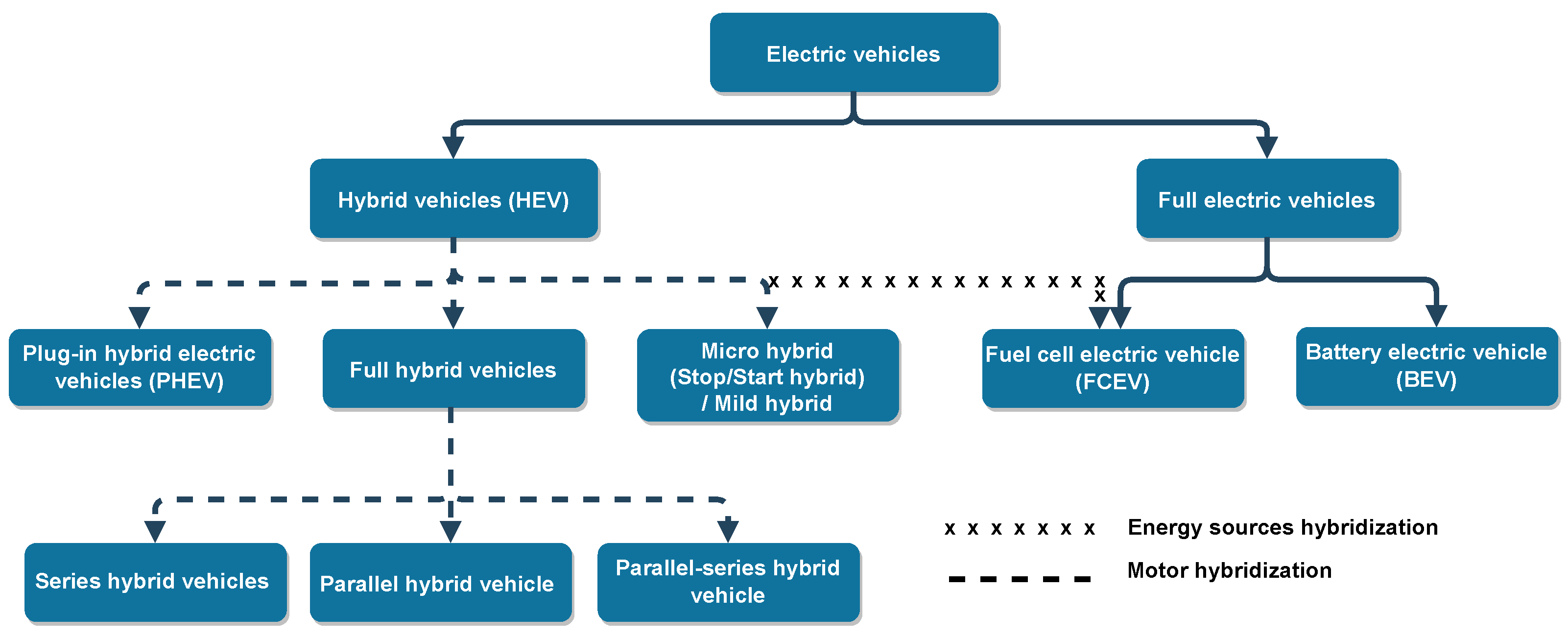
- Departing from a mechanical study and WLTP driving cycle, presenting the requirements in terms of torque, power, and energy of a vehicle. Then, presenting all possible technologies of vehicles: ICE vehicles, hybrid vehicles, and electric vehicles.
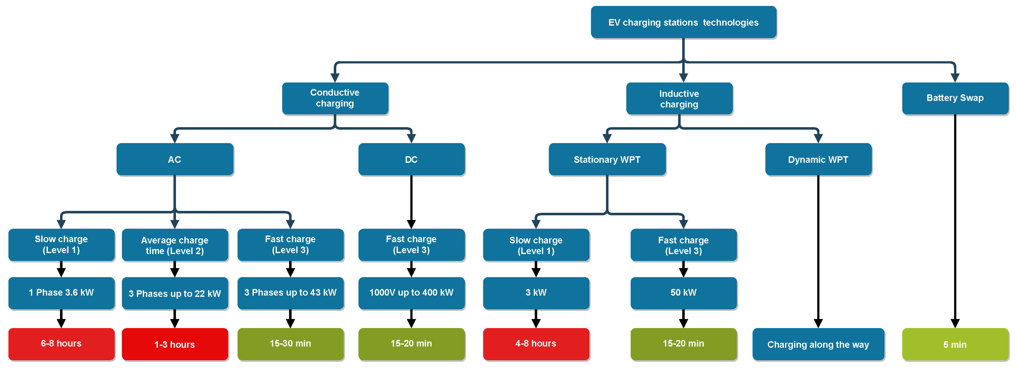
- Presenting charging stations technologies for electric vehicles and refueling stations for fuel cell vehicles.
2.1. Power and Energy Requirements
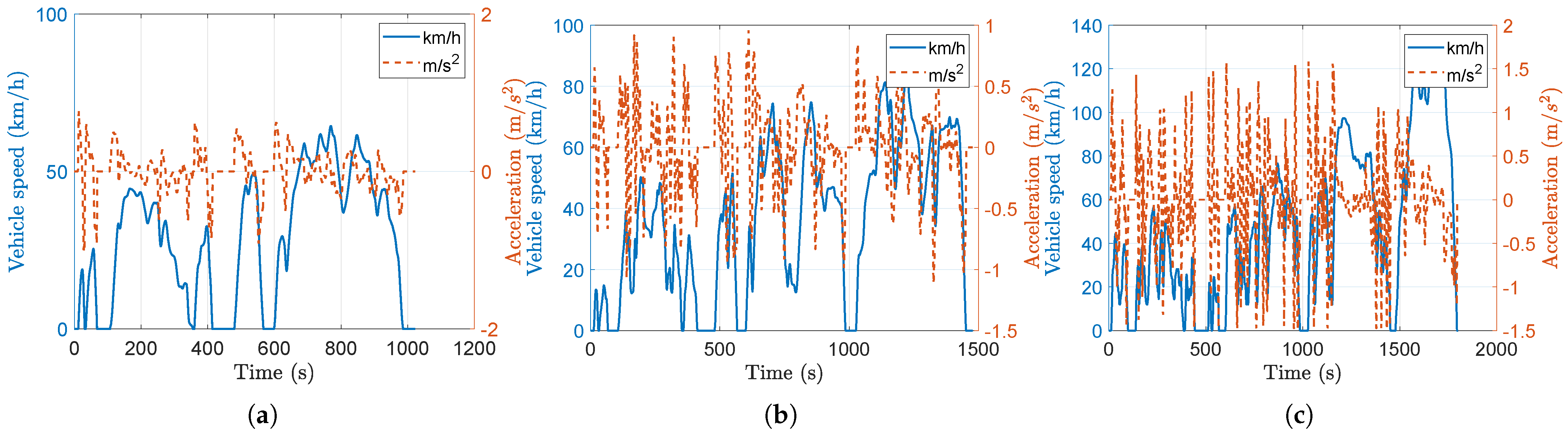
2.1.1. Worldwide Harmonized Light Vehicles Test Procedures
- Class 1 concerns vehicles for which the ratio of rated power in W/kg
- Class 2 is related to vehicles with ratio of rated power in W/kg but
- Class 3 focuses on vehicles with ratio of rated power in W/kg . The majority of vehicles are included in class 3.
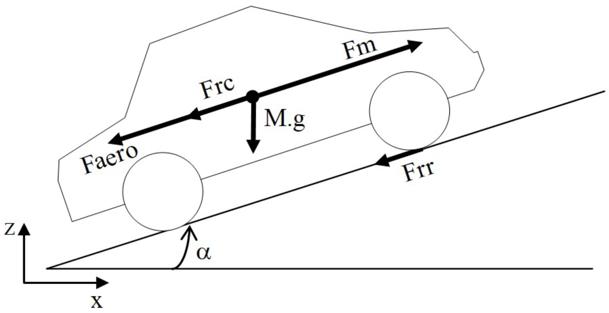
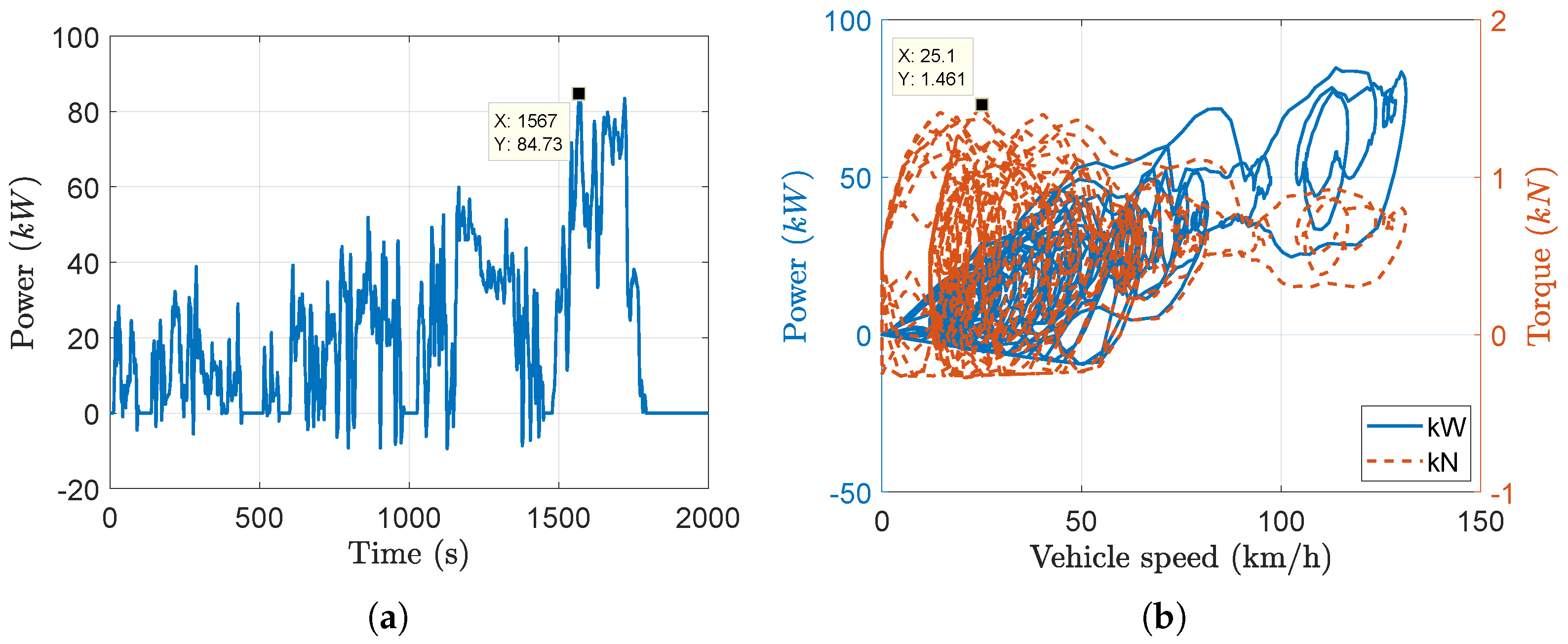
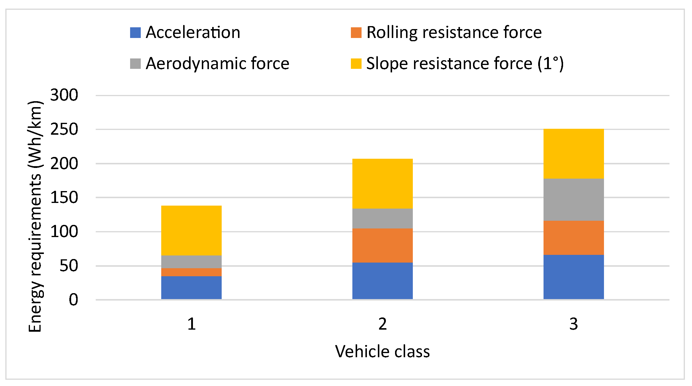
2.1.2. Numerical Study Results
- Aerodynamic force: ;
- Rolling resistance force: ;
- Slope resistance force: .
- Vehicle mass reduction: the objective in automotive industry is to reduce weight by with a cost limit of 500 € per 100 kg.
- Aerodynamics improvement:
- −
- No significant improvement of (minimum of ).
- −
- Vehicle frontal area reduction.
- Total road load power reduction by improving tire technology.
- Evolution of road infrastructure: traffic management and pavement improvement.
- Eco-driving: driving as safely and smoothly as possible to reduce energy consumption and limit pollutant emissions.
2.2. Vehicles Technologies
2.2.1. Internal Combustion Engine Vehicles
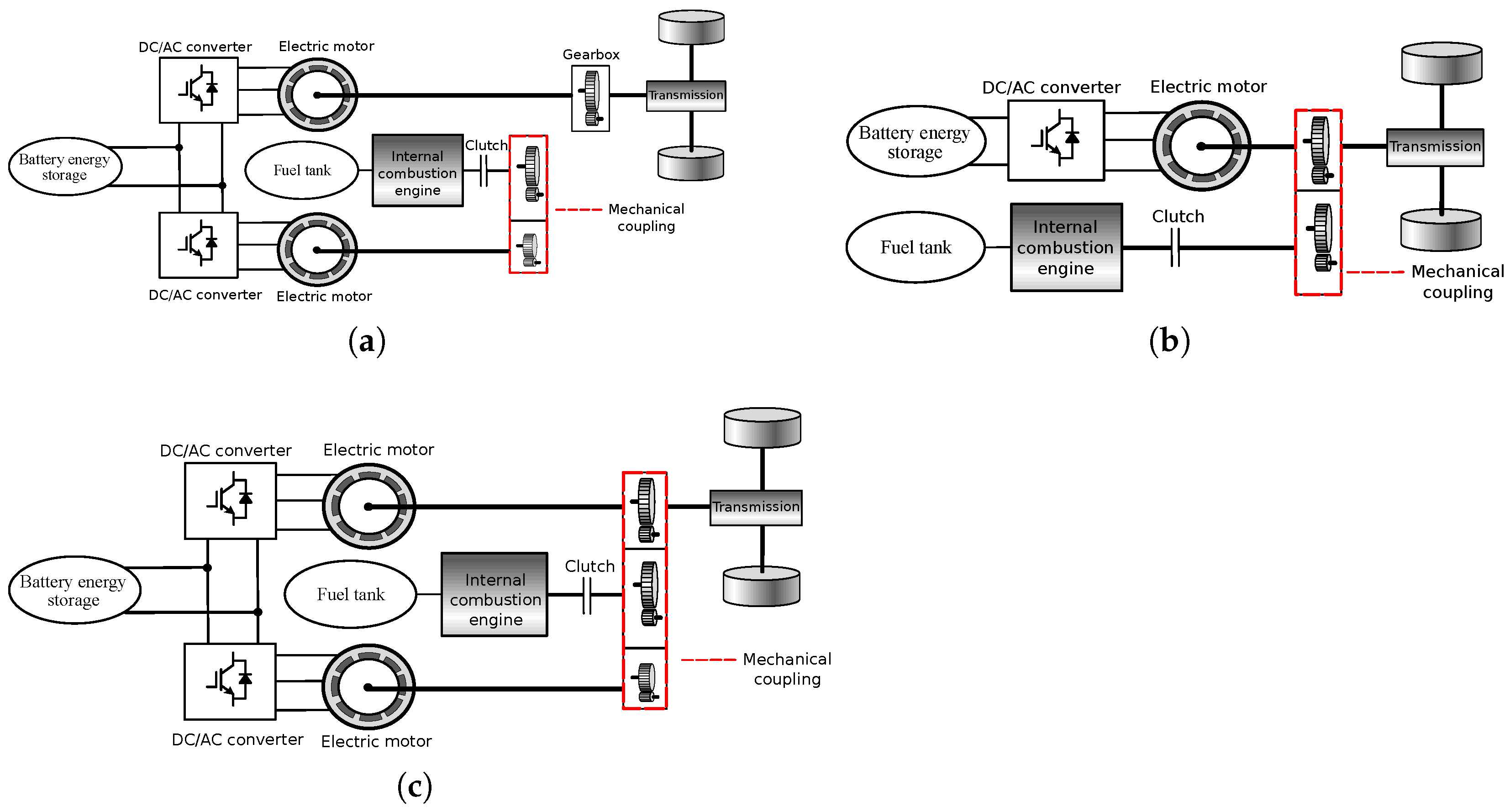
2.2.2. Hybrid and Plug-In Hybrid Vehicles
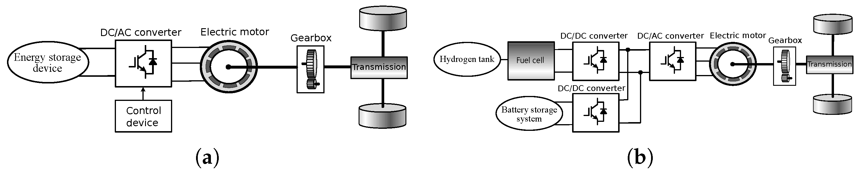
2.2.3. Battery Electric Vehicles
2.2.4. Fuel Cell Electric Vehicles
2.3. Charging Stations
2.3.1. Electric Vehicle Supply Equipment
2.3.2. EV Charging Modes and Charging Stations Level
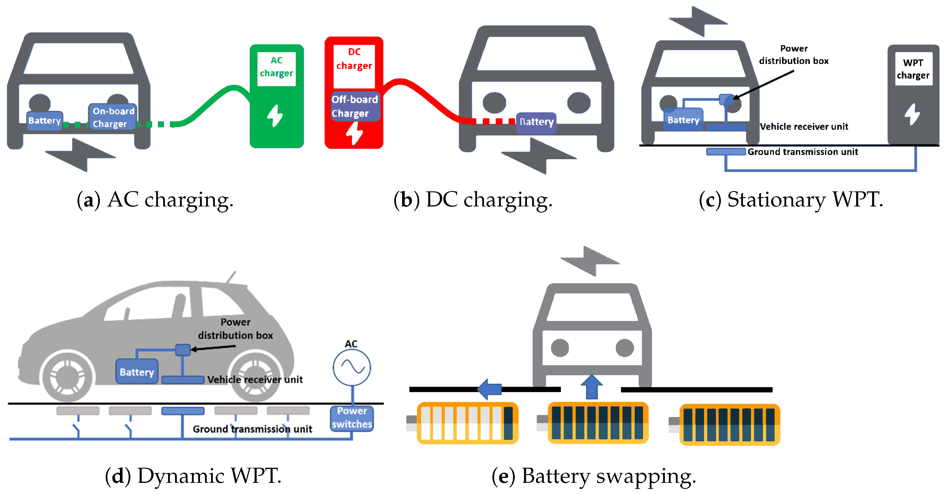
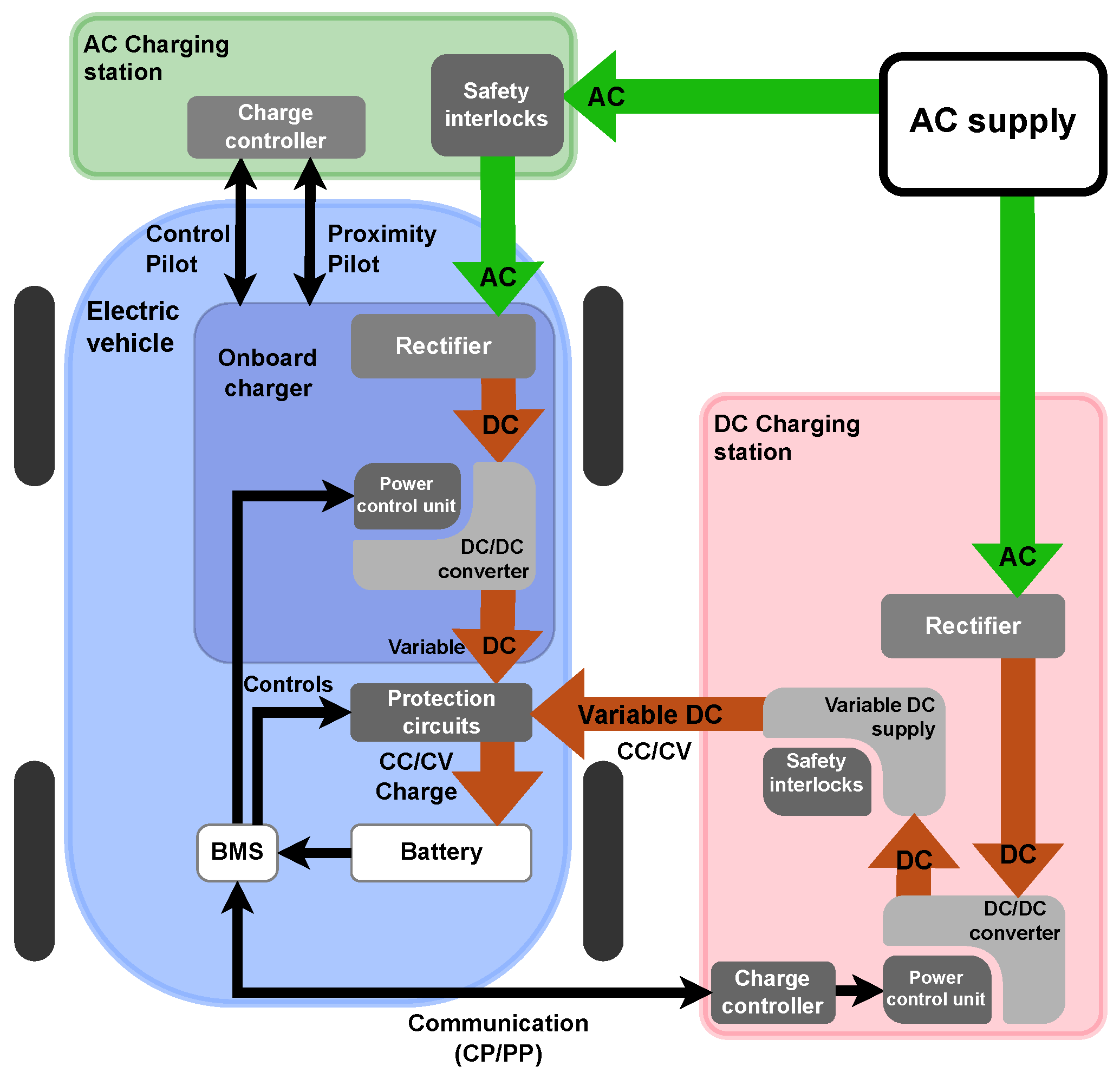
- Conductive chargers:Conductive chargers can be either on-board or off-board. On-board chargers are AC chargers that are limited in terms of size and nominal power. The AC/DC conversion is performed within the vehicle, which may offer the possibility to use the traction energy conversion system for battery charging. Off-board chargers are DC chargers characterized by higher output power. Moreover, this configuration offers more flexibility in terms of the power that can be supplied. Conductive charging stations can be classified into three distinct levels. EVSEs are classified as Level 1, Level 2, and DC Fast Charger, which differs in terms of output power type and level. All vehicles can be connected to a Level 1 or Level 2 chargers [16,121]. However, some vehicles can not be charged at a level 3 charger because they exceed the limits set by the manufacturers, such as the limits related to the batteries charging rate.
- −
- Level 1 charger: Level 1 charging is via an on-board low power EV charger (do not exceed 2 kW). These chargers plug into a standard 220 V outlet (120 V in north America) and can recharge an EV for a range of 200 km in 20 h. Standard electrical outlets are available everywhere; level 1 charging is usually performed at homes and in the parking bays of residential buildings.
- −
- Level 2 charger: Level 2 chargers are generally AC chargers that are concerned with the following standards: type 1 (j1772), type 2 (mennekes), and AC Tesla charger. This level is based on the use of the EV’s on-board AC/DC charger designed for higher power ratings. Level 2 charging requires a fixed charging station powered by a separate 208 V or 240 V branch circuit. It requires specific equipment and installation for their deployment at domestic and commercial level.
- −
- Level 3 charger: Generally, DC chargers that are based on the use of the off-board EVSE offering a much higher power than level 1 and 2 and can charge an electric vehicle much faster (less than 1 h). These chargers are generally installed along highways. Level 3 should comply with the requirement of the following standards: type 2 DC (mennekes), CHAdeMO (JEV G105-1993), DC Tesla chargers, CCS combo, and GB/T.
- Inductive chargers:The inductive charger is a contactless power transfer (WPT) system allowing battery charging based on electromagnetic waves [122,123,124]. This type of charging is available in two configurations:
- −
- Stationary charging [124]: performed at a standstill in a parking space. This would eliminate the required terminals with charging triggering and payment being controlled via the electric vehicle multimedia system.
- −
- Dynamic charging [125]: EV charging performed while driving thanks to a device integrated along the road.
Wireless charging will effectively solve the problem of the multitude of charging ports that vary in shape, size, and pins configuration depending on EV brand and country. In fact, with the use of this charging method, all the electric vehicles will be charged with the same infrastructure and will be exempted from the use of conventional cables. Additionally, thanks to the system ground integration, it avoids any risk of vandalism or ripping off by a distracted driver and also eliminates any risk of electrocution as there is no electrical contact.Moreover, with dynamic inductive charging, it is possible to downsize the battery capacity, which will contribute to a considerable reduction in the EV cost. However, this charging method has some drawbacks. Indeed, the inductive charging method has a lower overall efficiency than the conductive charging method, as the power conversion process using an air gap is less efficient than the direct power transfer using cables. Furthermore, inductive charging efficiency decreases due to the misalignment between the transmitter and the receiver coils. - Battery swapping works on the basis of changing the depleted battery and replacing it with an identical battery with a charge. The process involves driving into a battery switch bay, and an automated process will position the vehicle, disconnect the current battery, and replace it with a fully charged battery. Depleted batteries are charged in the station for later use. The system operates under the business model that the EV user owns the vehicle, not the battery. The battery swapping remains the fastest method (equivalent to refueling time). However, this method is very difficult to implement as batteries must be standardized between several EV manufacturers. Additionally, users are more likely to reject the idea changing their batteries with others that may have poor health conditions. There are also significant cost and logistical issues, as enough extra batteries in switch bay are required to supply customers quickly.
3. Power Electronics for EV Charging Stations
3.1. Specifications
- Implement a power factor correction: absorb a sinusoidal current free of harmonics with a power factor equal to 1.
- Bidirectional power electronics topology that allow participating to the energy storage on the grid in order to implement a vehicle-to-grid or vehicle-to-home concept.
- Bidirectional power electronics topology that allow participating to the energy storage on the grid in order to implement a vehicle-to-grid or vehicle-to home-concept.
- Using the traction inverter in the EV charging power electronics.
- No additional filtering inductance by using traction motor windings.
- Possibility of balancing battery elementary cells by implementing a part of battery management system functions.
- Contactless power transfer.
3.2. Power Electronics Solutions
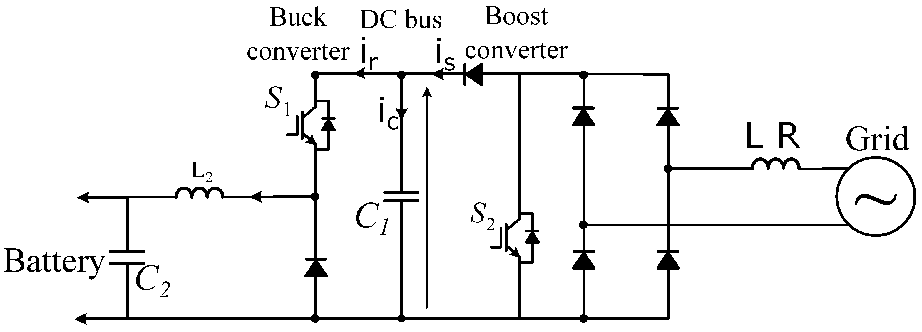
3.2.1. Unidirectional Battery Charger
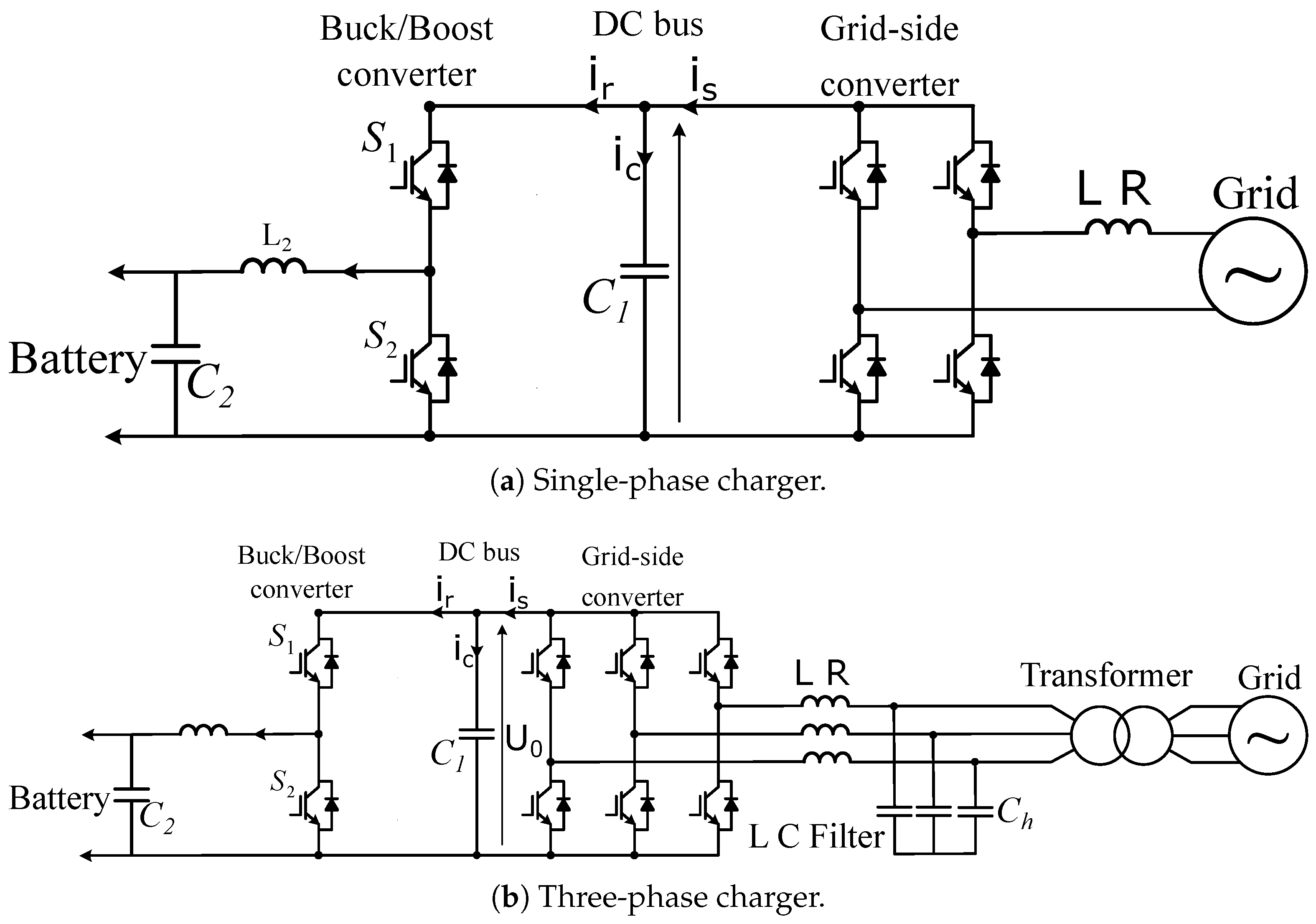
3.2.2. Bidirectional Battery Charger
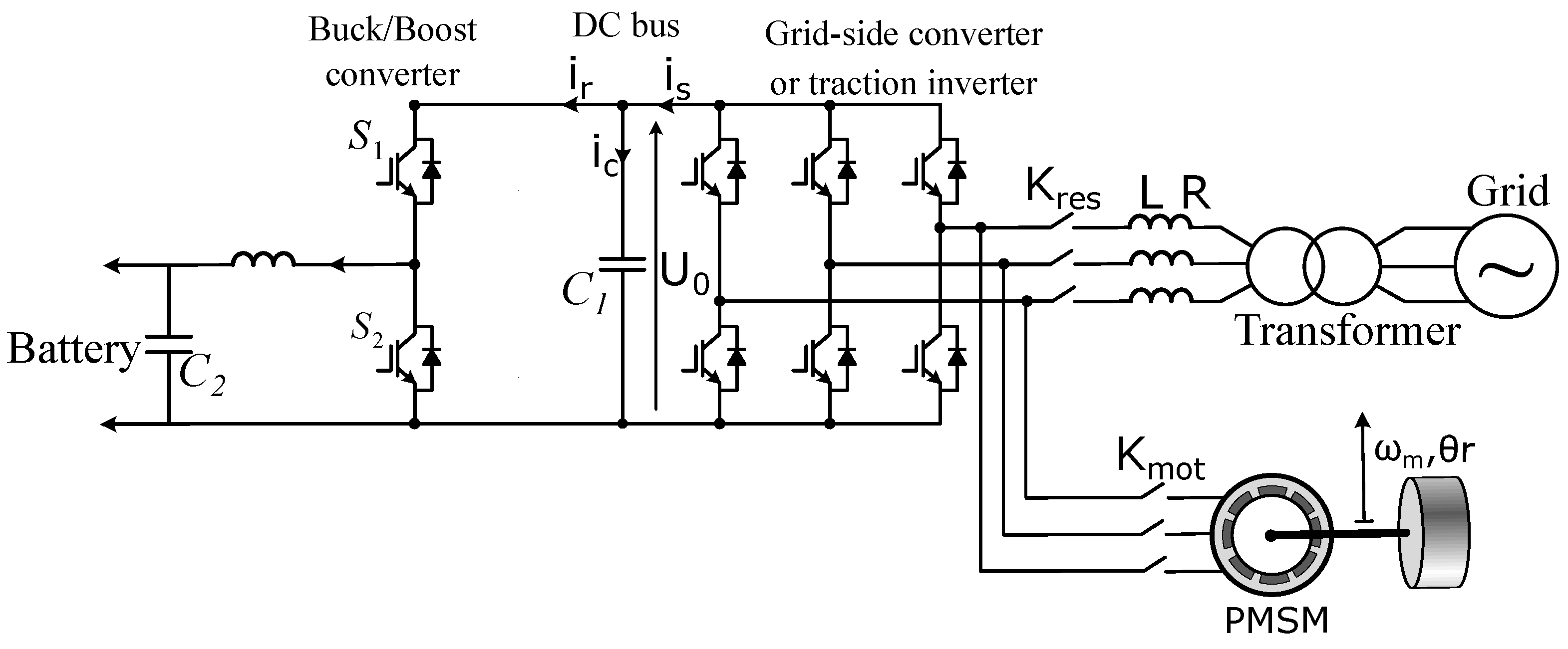
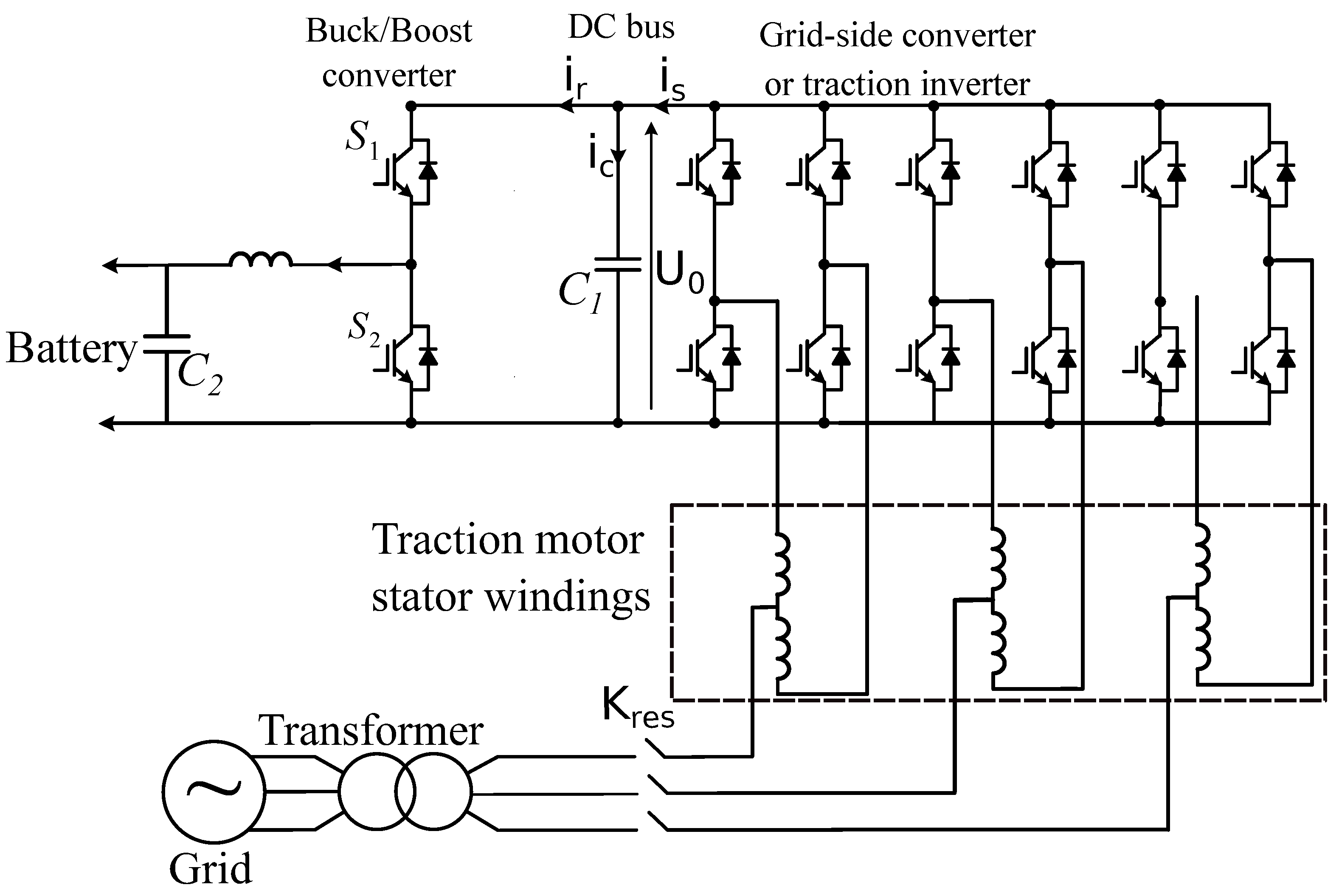
3.2.3. Integrated On-Board EV Charger
- Need for a specially designed electrical machine;
- Difficulty in accessing the neutral point of motor windings;
- Reduced reliability due to the use of mechanical contactors.
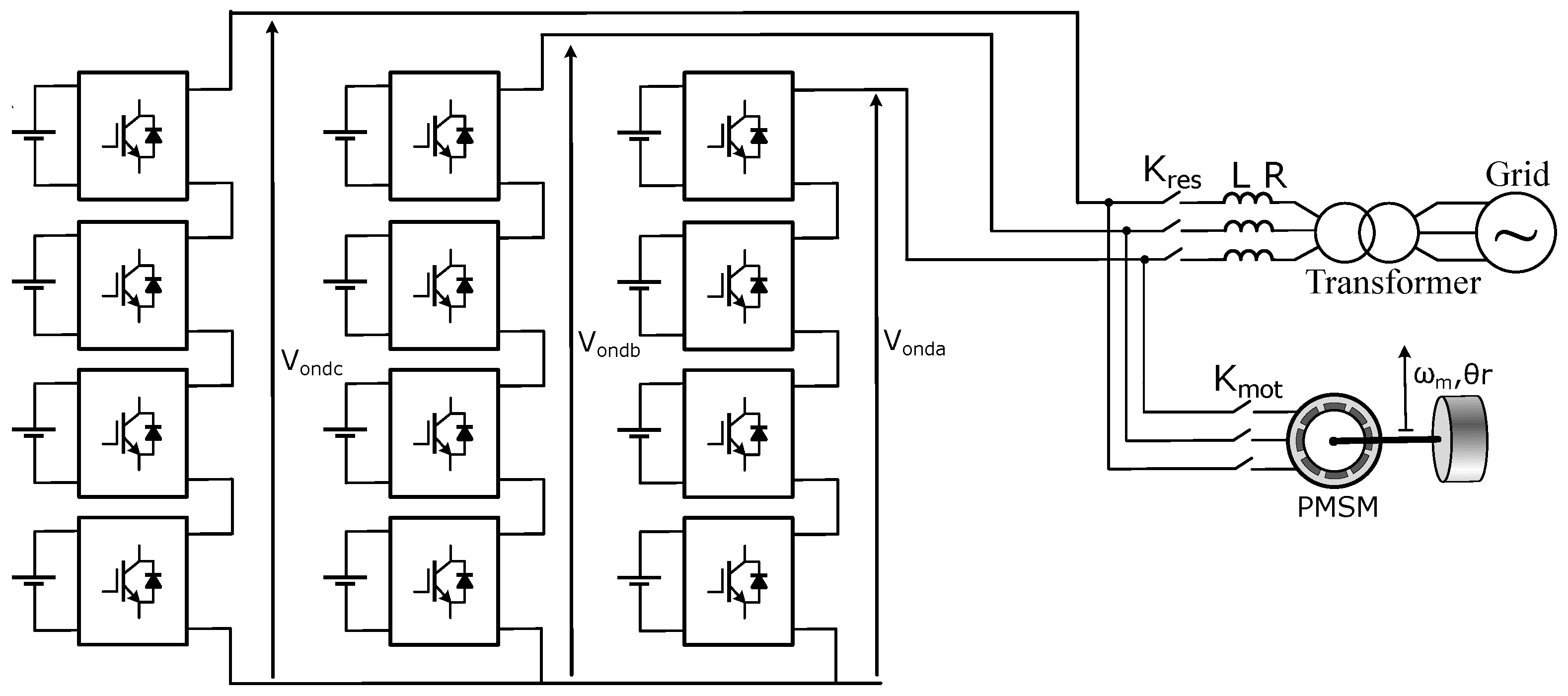
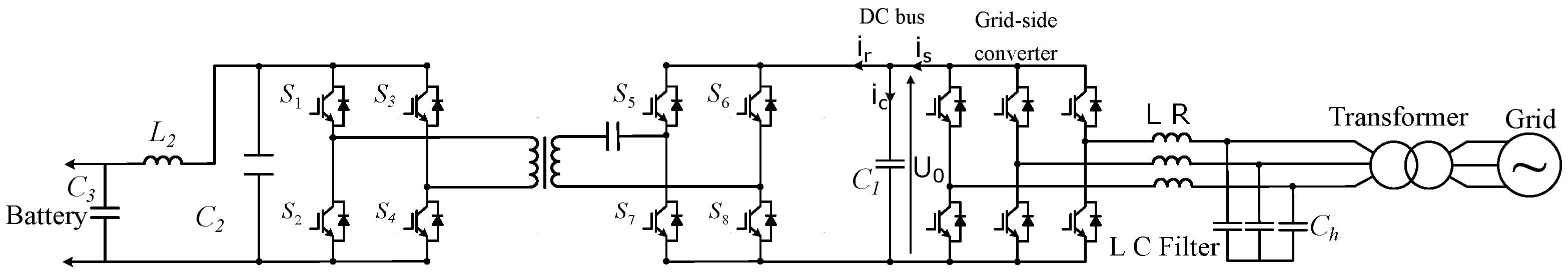
3.2.4. Bidirectional Battery Charger Using Modular Multilevel Converters
3.2.5. Contactless Power Transfer-Based EV Charger
3.3. Summary on EV Charging Stations Technical Requirements
4. Smart Charging and Grid Impact Mitigation
4.1. Charging Strategies
4.1.1. Dumb and Dual Pricing EV Charging
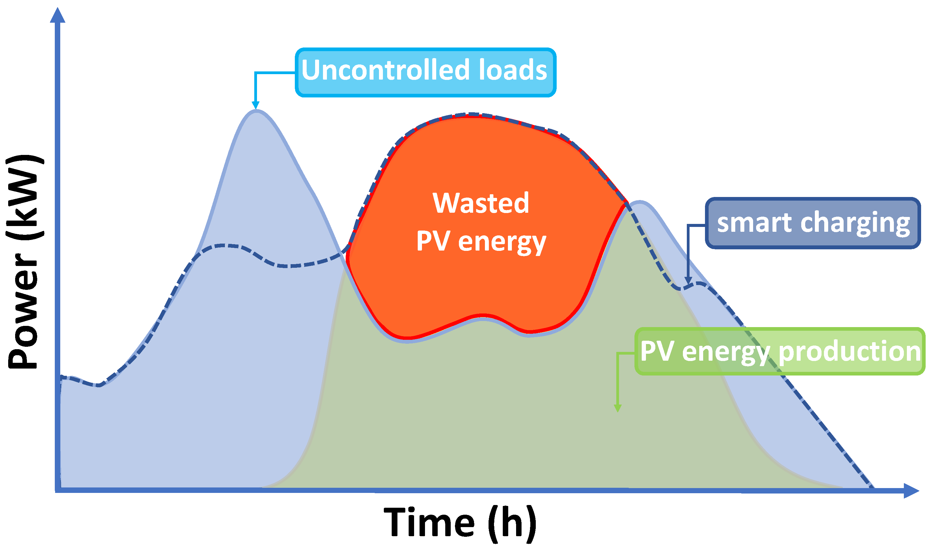
4.1.2. Smart Charging Stations
- Charging infrastructure high cost, including the information and communication technologies.
- Smart charging requires electric vehicles to be parked for long periods of time so that the system can control and schedule the power flow efficiently. This type of condition is relevant in specific locations such as workplace stations and commercial charging stations and is not suited for highways where customers are not expected to stay for long periods of time.
4.2. EV Chargers Impact on Power System and Mitigation Methods
- Development of high-voltage (up to 1000 V DC) off-board chargers to decrease charging time and reduce line currents and, consequently, to reduce thermal stress on distribution system components.
- Optimal and coordinated EV charging to relief the utility grid and the implementation of V2G and V2V concepts, which may allow reducing grid congestion and lower EV owners EV charging bill.
- Development of high efficiency WPT chargers.
- Use of wide-bandgap semiconductors, which are characterized by higher power density, higher efficiency and lower thermal stress.
5. Conclusions
Funding
Institutional Review Board Statement
Informed Consent Statement
Data Availability Statement
Conflicts of Interest
Abbreviations
| EV | Electric vehicle |
| FC | Fuel cell |
| ICE | Internal combustion engine |
| SOC | State of charge |
| WLTP | Worldwide harmonized Light vehicles Test Procedures |
| WLTC | Worldwide harmonized Light vehicles Test Cycles |
| BEV | Battery electric vehicle |
| FCEV | Fuel cell electric vehicle |
| WPT | Wireless power transfer |
| PHEV | Plug-in hybrid vehicle |
| BESS | Battery energy storage system |
| IPMSynRM | Internal permanent magnet synchronous reluctance motor |
| EVSE | Electric vehicle supply equipment |
| BMS | Battery management system |
| PQ | Power quality |
| AFE | Active font end |
| DBR | Diode bridge rectifier |
| V2G | Vehicle-to-grid |
| V2V | Vehicle-to-vehicle |
| PEI | Power electronic interface |
| THD | Total harmonic distortion |
| MMC | Modular multilevel converters |
| WBG | Wide-band-gap semiconductors |
| SiC | Silicon Carbide |
| GaN | Gallium Nitride |
| PFC | Power factor correction |
| IMN | Impedance matching network |
| DER | Distributed energy resources |
| ESS | Energy storage systems |
| RMS | Root mean square |
| PWM | Pulse width modulation |
| RES | Renewable energy resources |
| PV | Photovoltaic |
| IPT | Inductive power transfer |
| SOC | State of charge |
| TOU | Time-of-use |
| LTO | Lithium-Titanium-Oxide |
| NMC | Lithium-Nickel-Manganese-Cobalt-Oxide |
References
- Piasecki, S.; Zaleski, J.; Jasinski, M.; Bachman, S.; Turzyński, M. Analysis of AC/DC/DC Converter Modules for Direct Current Fast-Charging Applications. Energies 2021, 14, 6369. [Google Scholar] [CrossRef]
- Maroti, P.K.; Padmanaban, S.; Bhaskar, M.S.; Ramachandaramurthy, V.K.; Blaabjerg, F. The State-of-The-Art of Power Electronics Converters Configurations in Electric Vehicle Technologies. Power Electron. Devices Components 2021, 1, 100001. [Google Scholar] [CrossRef]
- Tahir, Y.; Khan, I.; Rahman, S.; Nadeem, M.F.; Iqbal, A.; Xu, Y.; Rafi, M. A state-of-the-art review on topologies and control techniques of solid-state transformers for electric vehicle extreme fast charging. IET Power Electron. 2021, 14, 1560–1576. [Google Scholar] [CrossRef]
- Sun, X.; Li, Z.; Wang, X.; Li, C. Technology development of electric vehicles: A review. Energies 2019, 13, 90. [Google Scholar] [CrossRef] [Green Version]
- Wahid, M.R.; Budiman, B.A.; Joelianto, E.; Aziz, M. A Review on Drive Train Technologies for Passenger Electric Vehicles. Energies 2021, 14, 6742. [Google Scholar] [CrossRef]
- Khalid, M.R.; Khan, I.A.; Hameed, S.; Asghar, M.J.; Ro, J.S. A comprehensive review on structural topologies, power levels, energy storage systems, and standards for electric vehicle charging stations and their impacts on grid. IEEE Access 2021, 9, 128069–128094. [Google Scholar] [CrossRef]
- Elbouchikhi, E.; Zia, M.F.; Benbouzid, M.; El Hani, S. Overview of Signal Processing and Machine Learning for Smart Grid Condition Monitoring. Electronics 2021, 10, 2725. [Google Scholar] [CrossRef]
- Ronanki, D.; Kelkar, A.; Williamson, S.S. Extreme fast charging technology—Prospects to enhance sustainable electric transportation. Energies 2019, 12, 3721. [Google Scholar] [CrossRef] [Green Version]
- Shin, M.; Kim, H.; Kim, H.; Jang, H. Building an interoperability test system for electric vehicle chargers based on ISO/IEC 15118 and IEC 61850 standards. Appl. Sci. 2016, 6, 165. [Google Scholar] [CrossRef] [Green Version]
- Savio Abraham, D.; Verma, R.; Kanagaraj, L.; Giri Thulasi Raman, S.R.; Rajamanickam, N.; Chokkalingam, B.; Marimuthu Sekar, K.; Mihet-Popa, L. Electric vehicles charging stations’ architectures, criteria, power converters, and control strategies in microgrids. Electronics 2021, 10, 1895. [Google Scholar] [CrossRef]
- Kumar K, J.; Kumar, S.; VS, N. Standards for electric vehicle charging stations in India: A review. Energy Storage 2022, 4, e261. [Google Scholar] [CrossRef]
- Bonsu, N.O. Towards a circular and low-carbon economy: Insights from the transitioning to electric vehicles and net zero economy. J. Clean. Prod. 2020, 256, 120659. [Google Scholar] [CrossRef]
- Cano, Z.P.; Banham, D.; Ye, S.; Hintennach, A.; Lu, J.; Fowler, M.; Chen, Z. Batteries and fuel cells for emerging electric vehicle markets. Nat. Energy 2018, 3, 279–289. [Google Scholar] [CrossRef]
- Sanguesa, J.A.; Torres-Sanz, V.; Garrido, P.; Martinez, F.J.; Marquez-Barja, J.M. A review on electric vehicles: Technologies and challenges. Smart Cities 2021, 4, 372–404. [Google Scholar] [CrossRef]
- Lai, X.; Chen, Q.; Tang, X.; Zhou, Y.; Gao, F.; Guo, Y.; Bhagat, R.; Zheng, Y. Critical review of life cycle assessment of lithium-ion batteries for electric vehicles: A lifespan perspective. eTransportation 2022, 12, 100169. [Google Scholar] [CrossRef]
- Das, H.S.; Rahman, M.M.; Li, S.; Tan, C. Electric vehicles standards, charging infrastructure, and impact on grid integration: A technological review. Renew. Sustain. Energy Rev. 2020, 120, 109618. [Google Scholar] [CrossRef]
- Wang, L.; Qin, Z.; Slangen, T.; Bauer, P.; Van Wijk, T. Grid impact of electric vehicle fast charging stations: Trends, standards, issues and mitigation measures-an overview. IEEE Open J. Power Electron. 2021, 2, 56–74. [Google Scholar] [CrossRef]
- Patil, H.; Kalkhambkar, V.N. Grid integration of electric vehicles for economic benefits: A review. J. Mod. Power Syst. Clean Energy 2020, 9, 13–26. [Google Scholar] [CrossRef]
- Mandrile, F.; Cittanti, D.; Mallemaci, V.; Bojoi, R. Electric vehicle ultra-fast battery chargers: A boost for power system stability? World Electr. Veh. J. 2021, 12, 16. [Google Scholar] [CrossRef]
- Suarez, C.; Martinez, W. Fast and ultra-fast charging for battery electric vehicles—A review. In Proceedings of the 2019 IEEE Energy Conversion Congress and Exposition (ECCE), Baltimore, MD, USA, 29 September–3 October 2019; pp. 569–575. [Google Scholar]
- Varga, B.O.; Sagoian, A.; Mariasiu, F. Prediction of electric vehicle range: A comprehensive review of current issues and challenges. Energies 2019, 12, 946. [Google Scholar] [CrossRef] [Green Version]
- Dlugosch, O.; Brandt, T.; Neumann, D. Combining analytics and simulation methods to assess the impact of shared, autonomous electric vehicles on sustainable urban mobility. Inf. Manag. 2020, 59, 103285. [Google Scholar] [CrossRef]
- Ongel, A.; Loewer, E.; Roemer, F.; Sethuraman, G.; Chang, F.; Lienkamp, M. Economic assessment of autonomous electric microtransit vehicles. Sustainability 2019, 11, 648. [Google Scholar] [CrossRef] [Green Version]
- Deng, J.; Bae, C.; Denlinger, A.; Miller, T. Electric vehicles batteries: Requirements and challenges. Joule 2020, 4, 511–515. [Google Scholar] [CrossRef]
- Temporelli, A.; Carvalho, M.L.; Girardi, P. Life cycle assessment of electric vehicle batteries: An overview of recent literature. Energies 2020, 13, 2864. [Google Scholar] [CrossRef]
- Crozier, C.; Morstyn, T.; McCulloch, M. The opportunity for smart charging to mitigate the impact of electric vehicles on transmission and distribution systems. Appl. Energy 2020, 268, 114973. [Google Scholar] [CrossRef]
- Sharma, A.; Sharma, S. Review of power electronics in vehicle-to-grid systems. J. Energy Storage 2019, 21, 337–361. [Google Scholar] [CrossRef]
- Taiebat, M.; Xu, M. Synergies of four emerging technologies for accelerated adoption of electric vehicles: Shared mobility, wireless charging, vehicle-to-grid, and vehicle automation. J. Clean. Prod. 2019, 230, 794–797. [Google Scholar] [CrossRef]
- Amamra, S.A.; Marco, J. Vehicle-to-grid aggregator to support power grid and reduce electric vehicle charging cost. IEEE Access 2019, 7, 178528–178538. [Google Scholar] [CrossRef]
- Heinisch, V.; Göransson, L.; Erlandsson, R.; Hodel, H.; Johnsson, F.; Odenberger, M. Smart electric vehicle charging strategies for sectoral coupling in a city energy system. Appl. Energy 2021, 288, 116640. [Google Scholar] [CrossRef]
- Khan, S.A.; Islam, M.R.; Guo, Y.; Zhu, J. A new isolated multi-port converter with multi-directional power flow capabilities for smart electric vehicle charging stations. IEEE Trans. Appl. Supercond. 2019, 29, 1–4. [Google Scholar] [CrossRef]
- Kouchachvili, L.; Yaïci, W.; Entchev, E. Hybrid battery/supercapacitor energy storage system for the electric vehicles. J. Power Sources 2018, 374, 237–248. [Google Scholar] [CrossRef]
- Lipman, T.E.; Elke, M.; Lidicker, J. Hydrogen fuel cell electric vehicle performance and user-response assessment: Results of an extended driver study. Int. J. Hydrogen Energy 2018, 43, 12442–12454. [Google Scholar] [CrossRef]
- Kurtz, J.M.; Sprik, S.; Saur, G.; Onorato, S. Fuel Cell Electric Vehicle Durability and Fuel Cell Performance; Technical report; National Renewable Energy Lab. (NREL): Golden, CO, USA, 2019.
- Lü, X.; Wu, Y.; Lian, J.; Zhang, Y.; Chen, C.; Wang, P.; Meng, L. Energy management of hybrid electric vehicles: A review of energy optimization of fuel cell hybrid power system based on genetic algorithm. Energy Convers. Manag. 2020, 205, 112474. [Google Scholar] [CrossRef]
- Singh, K.V.; Bansal, H.O.; Singh, D. A comprehensive review on hybrid electric vehicles: Architectures and components. J. Mod. Transp. 2019, 27, 77–107. [Google Scholar] [CrossRef] [Green Version]
- Zhuang, W.; Li, S.; Zhang, X.; Kum, D.; Song, Z.; Yin, G.; Ju, F. A survey of powertrain configuration studies on hybrid electric vehicles. Appl. Energy 2020, 262, 114553. [Google Scholar] [CrossRef]
- Chakraborty, S.; Vu, H.N.; Hasan, M.M.; Tran, D.D.; Baghdadi, M.E.; Hegazy, O. DC-DC converter topologies for electric vehicles, plug-in hybrid electric vehicles and fast charging stations: State of the art and future trends. Energies 2019, 12, 1569. [Google Scholar] [CrossRef] [Green Version]
- Albatayneh, A.; Assaf, M.N.; Alterman, D.; Jaradat, M. Comparison of the overall energy efficiency for internal combustion engine vehicles and electric vehicles. Rigas Teh. Univ. Zinat. Raksti 2020, 24, 669–680. [Google Scholar] [CrossRef]
- Zeb, M.Z.; Imran, K.; Khattak, A.; Janjua, A.K.; Pal, A.; Nadeem, M.; Zhang, J.; Khan, S. Optimal placement of electric vehicle charging stations in the active distribution network. IEEE Access 2020, 8, 68124–68134. [Google Scholar] [CrossRef]
- Zhao, Q.; Kelley, S.B.; Xiao, F.; Kuby, M.J. A multi-scale framework for fuel station location: From highways to street intersections. Transp. Res. Part D Transp. Environ. 2019, 74, 48–64. [Google Scholar] [CrossRef]
- Zhang, Y.; Zhang, Q.; Farnoosh, A.; Chen, S.; Li, Y. GIS-based multi-objective particle swarm optimization of charging stations for electric vehicles. Energy 2019, 169, 844–853. [Google Scholar] [CrossRef]
- He, Y.; Kockelman, K.M.; Perrine, K.A. Optimal locations of US fast charging stations for long-distance trip completion by battery electric vehicles. J. Clean. Prod. 2019, 214, 452–461. [Google Scholar] [CrossRef]
- Deb, S.; Tammi, K.; Kalita, K.; Mahanta, P. Review of recent trends in charging infrastructure planning for electric vehicles. Wiley Interdiscip. Rev. Energy Environ. 2018, 7, e306. [Google Scholar] [CrossRef] [Green Version]
- Rajendran, G.; Vaithilingam, C.A.; Misron, N.; Naidu, K.; Ahmed, M.R. A comprehensive review on system architecture and international standards for electric vehicle charging stations. J. Energy Storage 2021, 42, 103099. [Google Scholar] [CrossRef]
- Sovacool, B.K.; Kester, J.; Noel, L.; de Rubens, G.Z. Actors, business models, and innovation activity systems for vehicle-to-grid (V2G) technology: A comprehensive review. Renew. Sustain. Energy Rev. 2020, 131, 109963. [Google Scholar] [CrossRef]
- Ustun, T.S.; Ozansoy, C.R.; Zayegh, A. Implementing vehicle-to-grid (V2G) technology with IEC 61850-7-420. IEEE Trans. Smart Grid 2013, 4, 1180–1187. [Google Scholar] [CrossRef]
- Shirazi, Y.; Carr, E.; Knapp, L. A cost-benefit analysis of alternatively fueled buses with special considerations for V2G technology. Energy Policy 2015, 87, 591–603. [Google Scholar] [CrossRef]
- Emadi, A.; Lee, Y.J.; Rajashekara, K. Power electronics and motor drives in electric, hybrid electric, and plug-in hybrid electric vehicles. IEEE Trans. Ind. Electron. 2008, 55, 2237–2245. [Google Scholar] [CrossRef]
- Demuynck, J.; Bosteels, D.; De Paepe, M.; Favre, C.; May, J.; Verhelst, S. Recommendations for the new WLTP cycle based on an analysis of vehicle emission measurements on NEDC and CADC. Energy Policy 2012, 49, 234–242. [Google Scholar] [CrossRef] [Green Version]
- Massaguer, E.; Massaguer, A.; Pujol, T.; Comamala, M.; Montoro, L.; Gonzalez, J. Fuel economy analysis under a WLTP cycle on a mid-size vehicle equipped with a thermoelectric energy recovery system. Energy 2019, 179, 306–314. [Google Scholar] [CrossRef]
- Tutuianu, M.; Bonnel, P.; Ciuffo, B.; Haniu, T.; Ichikawa, N.; Marotta, A.; Pavlovic, J.; Steven, H. Development of the World-wide harmonized Light duty Test Cycle (WLTC) and a possible pathway for its introduction in the European legislation. Transp. Res. Part D Transp. Environ. 2015, 40, 61–75. [Google Scholar] [CrossRef]
- Tsiakmakis, S.; Fontaras, G.; Cubito, C.; Pavlovic, J.; Anagnostopoulos, K.; Ciuffo, B. From NEDC to WLTP: Effect on the Type-Approval CO2 Emissions of Light-Duty Vehicles; Publications Office of the European Union: Luxembourg, 2017; p. 50. [Google Scholar]
- Mock, P.; Kühlwein, J.; Tietge, U.; Franco, V.; Bandivadekar, A.; German, J. The WLTP: How a new test procedure for cars will affect fuel consumption values in the EU. Int. Counc. Clean Transp. 2014, 9, 1–20. [Google Scholar]
- Cubito, C.; Millo, F.; Boccardo, G.; Di Pierro, G.; Ciuffo, B.; Fontaras, G.; Serra, S.; Otura Garcia, M.; Trentadue, G. Impact of different driving cycles and operating conditions on CO2 emissions and energy management strategies of a Euro-6 hybrid electric vehicle. Energies 2017, 10, 1590. [Google Scholar] [CrossRef]
- Gauchia, L.; Bouscayrol, A.; Sanz, J.; Trigui, R.; Barrade, P. Fuel cell, battery and supercapacitor hybrid system for electric vehicle: Modeling and control via energetic macroscopic representation. In Proceedings of the 2011 IEEE Vehicle Power and Propulsion Conference, Chicago, IL, USA, 6–9 September 2011; pp. 1–6. [Google Scholar]
- Liu, W. Hybrid Electric Vehicle System Modeling and Control; John Wiley & Sons: New York, NY, USA, 2017. [Google Scholar]
- Ayyildiz, K.; Cavallaro, F.; Nocera, S.; Willenbrock, R. Reducing fuel consumption and carbon emissions through eco-drive training. Transp. Res. Part F Traffic Psychol. Behav. 2017, 46, 96–110. [Google Scholar] [CrossRef]
- Shaheen, S.A.; Lipman, T.E. Reducing greenhouse emissions and fuel consumption: Sustainable approaches for surface transportation. IATSS Res. 2007, 31, 6–20. [Google Scholar] [CrossRef] [Green Version]
- Ajanovic, A. The future of electric vehicles: Prospects and impediments. Wiley Interdiscip. Rev. Energy Environ. 2015, 4, 521–536. [Google Scholar] [CrossRef]
- Alobeidli, K.; Khadkikar, V. A new ultracapacitor state of charge control concept to enhance battery lifespan of dual storage electric vehicles. IEEE Trans. Veh. Technol. 2018, 67, 10470–10481. [Google Scholar] [CrossRef]
- Ferguson, C.R.; Kirkpatrick, A.T. Internal Combustion Engines: Applied Thermosciences; John Wiley & Sons: New York, NY, USA, 2015. [Google Scholar]
- Gupta, H.N. Fundamentals of Internal Combustion Engines; PHI Learning Pvt. Ltd.: Delhi, India, 2012. [Google Scholar]
- Ganesan, V. Internal Combustion Engines; McGraw Hill Education (India) Pvt Ltd.: Delhi, India, 2012. [Google Scholar]
- Bae, C.; Kim, J. Alternative fuels for internal combustion engines. Proc. Combust. Inst. 2017, 36, 3389–3413. [Google Scholar] [CrossRef]
- Alagumalai, A. Internal combustion engines: Progress and prospects. Renew. Sustain. Energy Rev. 2014, 38, 561–571. [Google Scholar] [CrossRef]
- Verhelst, S.; Wallner, T. Hydrogen-fueled internal combustion engines. Prog. Energy Combust. Sci. 2009, 35, 490–527. [Google Scholar] [CrossRef] [Green Version]
- Pulkrabek, W.W. Engineering Fundamentals of the Internal Combustion Engine; Pearson PLC: London, UK, 2004. [Google Scholar]
- Heywood, J.B. Combustion engine fundamentals. 1ª Edição. Estados Unidos 1988, 25, 1117–1128. [Google Scholar]
- Mi, C.; Masrur, M.A. Hybrid Electric Vehicles: Principles and Applications with Practical Perspectives; John Wiley & Sons: New York, NY, USA, 2017. [Google Scholar]
- Hannan, M.A.; Azidin, F.; Mohamed, A. Hybrid electric vehicles and their challenges: A review. Renew. Sustain. Energy Rev. 2014, 29, 135–150. [Google Scholar] [CrossRef]
- Chau, K.; Wong, Y. Overview of power management in hybrid electric vehicles. Energy Convers. Manag. 2002, 43, 1953–1968. [Google Scholar] [CrossRef]
- Onori, S.; Serrao, L.; Rizzoni, G. Hybrid Electric Vehicles: Energy Management Strategies; Springer: Berlin, Gernamy, 2016. [Google Scholar]
- Chau, K.; Chan, C.C. Emerging energy-efficient technologies for hybrid electric vehicles. Proc. IEEE 2007, 95, 821–835. [Google Scholar] [CrossRef]
- Chen, B.; Evangelou, S.A.; Lot, R. Series hybrid electric vehicle simultaneous energy management and driving speed optimization. IEEE/ASME Trans. Mechatronics 2019, 24, 2756–2767. [Google Scholar] [CrossRef] [Green Version]
- Li, S.G.; Sharkh, S.M.; Walsh, F.C.; Zhang, C.N. Energy and battery management of a plug-in series hybrid electric vehicle using fuzzy logic. IEEE Trans. Veh. Technol. 2011, 60, 3571–3585. [Google Scholar] [CrossRef]
- Sciarretta, A.; Back, M.; Guzzella, L. Optimal control of parallel hybrid electric vehicles. IEEE Trans. Control. Syst. Technol. 2004, 12, 352–363. [Google Scholar] [CrossRef]
- Boyali, A.; Demirci, M.; Acarman, T.; Guvenc, L.; Tur, O.; Uçarol, H.; Kiray, B.; Ozatay, E. Modeling and control of a four wheel drive parallel hybrid electric vehicle. In Proceedings of the 2006 IEEE Conference on Computer Aided Control System Design, 2006 IEEE International Conference on Control Applications, 2006 IEEE International Symposium on Intelligent Control, Munich, Germany, 4–6 October 2006; pp. 155–162. [Google Scholar]
- Anselma, P.G.; Belingardi, G.; Falai, A.; Maino, C.; Miretti, F.; Misul, D.; Spessa, E. Comparing parallel hybrid electric vehicle powertrains for real-world driving. In Proceedings of the 2019 AEIT International conference of electrical and electronic technologies for Automotive (AEIT AUTOMOTIVE), Turin, Italy, 2–4 July 2019; pp. 1–6. [Google Scholar]
- Han, S.; Zhang, F.; Xi, J. A real-time energy management strategy based on energy prediction for parallel hybrid electric vehicles. IEEE Access 2018, 6, 70313–70323. [Google Scholar] [CrossRef]
- Anselma, P.G.; Biswas, A.; Belingardi, G.; Emadi, A. Rapid assessment of the fuel economy capability of parallel and series-parallel hybrid electric vehicles. Appl. Energy 2020, 275, 115319. [Google Scholar] [CrossRef]
- Dong, H.; Fu, J.; Zhao, Z.; Liu, Q.; Li, Y.; Liu, J. A comparative study on the energy flow of a conventional gasoline-powered vehicle and a new dual clutch parallel-series plug-in hybrid electric vehicle under NEDC. Energy Convers. Manag. 2020, 218, 113019. [Google Scholar] [CrossRef]
- Zeng, X.; Li, M.; Abd El-Hady, D.; Alshitari, W.; Al-Bogami, A.S.; Lu, J.; Amine, K. Commercialization of lithium battery technologies for electric vehicles. Adv. Energy Mater. 2019, 9, 1900161. [Google Scholar] [CrossRef]
- Aghabali, I.; Bauman, J.; Kollmeyer, P.J.; Wang, Y.; Bilgin, B.; Emadi, A. 800-V Electric Vehicle Powertrains: Review and Analysis of Benefits, Challenges, and Future Trends. IEEE Trans. Transp. Electrif. 2020, 7, 927–948. [Google Scholar] [CrossRef]
- Allca-Pekarovic, A.; Kollmeyer, P.J.; Mahvelatishamsabadi, P.; Mirfakhrai, T.; Naghshtabrizi, P.; Emadi, A. Comparison of igbt and sic inverter loss for 400v and 800v dc bus electric vehicle drivetrains. In Proceedings of the 2020 IEEE Energy Conversion Congress and Exposition (ECCE), Detroit, MI, USA, 11–15 October 2020; pp. 6338–6344. [Google Scholar]
- Wang, Z.; Ching, T.W.; Huang, S.; Wang, H.; Xu, T. Challenges faced by electric vehicle motors and their solutions. IEEE Access 2020, 9, 5228–5249. [Google Scholar] [CrossRef]
- Gan, C.; Wu, J.; Sun, Q.; Kong, W.; Li, H.; Hu, Y. A review on machine topologies and control techniques for low-noise switched reluctance motors in electric vehicle applications. IEEE Access 2018, 6, 31430–31443. [Google Scholar] [CrossRef]
- Lan, Y.; Benomar, Y.; Deepak, K.; Aksoz, A.; Baghdadi, M.E.; Bostanci, E.; Hegazy, O. Switched reluctance motors and drive systems for electric vehicle powertrains: State of the art analysis and future trends. Energies 2021, 14, 2079. [Google Scholar] [CrossRef]
- Redelbach, M.; Özdemir, E.D.; Friedrich, H.E. Optimizing battery sizes of plug-in hybrid and extended range electric vehicles for different user types. Energy Policy 2014, 73, 158–168. [Google Scholar] [CrossRef] [Green Version]
- Zhu, T.; Lot, R.; Wills, R.G.; Yan, X. Sizing a battery-supercapacitor energy storage system with battery degradation consideration for high-performance electric vehicles. Energy 2020, 208, 118336. [Google Scholar] [CrossRef]
- Zhang, L.; Hu, X.; Wang, Z.; Sun, F.; Deng, J.; Dorrell, D.G. Multiobjective optimal sizing of hybrid energy storage system for electric vehicles. IEEE Trans. Veh. Technol. 2017, 67, 1027–1035. [Google Scholar] [CrossRef]
- Saw, L.; Ye, Y.; Tay, A. Electro-thermal analysis and integration issues of lithium ion battery for electric vehicles. Appl. Energy 2014, 131, 97–107. [Google Scholar] [CrossRef]
- Zhao, J.; Rao, Z.; Huo, Y.; Liu, X.; Li, Y. Thermal management of cylindrical power battery module for extending the life of new energy electric vehicles. Appl. Therm. Eng. 2015, 85, 33–43. [Google Scholar] [CrossRef]
- Shen, J.; Dusmez, S.; Khaligh, A. Optimization of sizing and battery cycle life in battery/ultracapacitor hybrid energy storage systems for electric vehicle applications. IEEE Trans. Ind. Inform. 2014, 10, 2112–2121. [Google Scholar] [CrossRef]
- Zhu, T.; Wills, R.G.; Lot, R.; Kong, X.; Yan, X. Optimal sizing and sensitivity analysis of a battery-supercapacitor energy storage system for electric vehicles. Energy 2021, 221, 119851. [Google Scholar] [CrossRef]
- İnci, M.; Büyük, M.; Demir, M.H.; İlbey, G. A review and research on fuel cell electric vehicles: Topologies, power electronic converters, energy management methods, technical challenges, marketing and future aspects. Renew. Sustain. Energy Rev. 2021, 137, 110648. [Google Scholar] [CrossRef]
- Gaikwad, S.D.; Ghosh, P.C. Sizing of a fuel cell electric vehicle: A pinch analysis-based approach. Int. J. Hydrogen Energy 2020, 45, 8985–8993. [Google Scholar] [CrossRef]
- Yoo, E.; Kim, M.; Song, H.H. Well-to-wheel analysis of hydrogen fuel-cell electric vehicle in Korea. Int. J. Hydrogen Energy 2018, 43, 19267–19278. [Google Scholar] [CrossRef]
- Nassif, G.G.; de Almeida, S.C. Impact of powertrain hybridization on the performance and costs of a fuel cell electric vehicle. Int. J. Hydrogen Energy 2020, 45, 21722–21737. [Google Scholar] [CrossRef]
- Carello, M.; de Carvalho Pinheiro, H.; Longega, L.; Di Napoli, L. Design and modelling of the powertrain of a hybrid fuel cell electric vehicle. SAE Int. J. Adv. Curr. Pract. Mobil. 2021, 3, 2878–2892. [Google Scholar]
- Dépature, C.; Jemei, S.; Boulon, L.; Bouscayrol, A.; Marx, N.; Morando, S.; Castaings, A. Energy management in fuel-cell/battery vehicles: Key issues identified in the IEEE vehicular technology society motor vehicle challenge 2017. IEEE Veh. Technol. Mag. 2018, 13, 144–151. [Google Scholar] [CrossRef]
- Nguyen, B.H.; German, R.; Trovão, J.P.F.; Bouscayrol, A. Real-time energy management of battery/supercapacitor electric vehicles based on an adaptation of Pontryagin’s minimum principle. IEEE Trans. Veh. Technol. 2018, 68, 203–212. [Google Scholar] [CrossRef] [Green Version]
- Ogawa, T.; Takeuchi, M.; Kajikawa, Y. Comprehensive analysis of trends and emerging technologies in all types of fuel cells based on a computational method. Sustainability 2018, 10, 458. [Google Scholar] [CrossRef] [Green Version]
- Pu, Z.; Zhang, G.; Hassanpour, A.; Zheng, D.; Wang, S.; Liao, S.; Chen, Z.; Sun, S. Regenerative fuel cells: Recent progress, challenges, perspectives and their applications for space energy system. Appl. Energy 2021, 283, 116376. [Google Scholar] [CrossRef]
- Ma, M.; Yang, X.; Qiao, J.; Sun, W.; Wang, Z.; Sun, K. Progress and challenges of carbon-fueled solid oxide fuel cells anode. J. Energy Chem. 2021, 56, 209–222. [Google Scholar] [CrossRef]
- Atilhan, S.; Park, S.; El-Halwagi, M.M.; Atilhan, M.; Moore, M.; Nielsen, R.B. Green hydrogen as an alternative fuel for the shipping industry. Curr. Opin. Chem. Eng. 2021, 31, 100668. [Google Scholar] [CrossRef]
- Dincer, I. Green methods for hydrogen production. Int. J. Hydrogen Energy 2012, 37, 1954–1971. [Google Scholar] [CrossRef]
- Barbir, F.; Gomez, T. Efficiency and economics of proton exchange membrane (PEM) fuel cells. Int. J. Hydrogen Energy 1997, 22, 1027–1037. [Google Scholar] [CrossRef]
- Hernández-Gómez, Á.; Ramirez, V.; Guilbert, D. Investigation of PEM electrolyzer modeling: Electrical domain, efficiency, and specific energy consumption. Int. J. Hydrogen Energy 2020, 45, 14625–14639. [Google Scholar] [CrossRef]
- Kurtz, J.; Sprik, S.; Bradley, T.H. Review of transportation hydrogen infrastructure performance and reliability. Int. J. Hydrogen Energy 2019, 44, 12010–12023. [Google Scholar] [CrossRef]
- Wang, B.; Dehghanian, P.; Wang, S.; Mitolo, M. Electrical safety considerations in large-scale electric vehicle charging stations. IEEE Trans. Ind. Appl. 2019, 55, 6603–6612. [Google Scholar] [CrossRef]
- Brooker, R.P.; Qin, N. Identification of potential locations of electric vehicle supply equipment. J. Power Sources 2015, 299, 76–84. [Google Scholar] [CrossRef]
- Alghamdi, T.G.; Said, D.; Mouftah, H.T. Decentralized electric vehicle supply stations (D-EVSSs): A realistic scenario for smart cities. IEEE Access 2019, 7, 63016–63026. [Google Scholar] [CrossRef]
- Han, A.; Shin, M.; Kim, I.; Jang, H.S. A study on communication controller of electric vehicle supply equipment for information exchange between electric vehicle and power grid. Trans. Korean Inst. Electr. Eng. 2014, 63, 1564–1570. [Google Scholar] [CrossRef]
- García-Martínez, E.; Muñoz-Cruzado-Alba, J.; Sanz-Osorio, J.F.; Perié, J.M. Design and Experimental Validation of Power Electric Vehicle Emulator for Testing Electric Vehicle Supply Equipment (EVSE) with Vehicle-to-Grid (V2G) Capability. Appl. Sci. 2021, 11, 11496. [Google Scholar] [CrossRef]
- Bosshard, R.; Kolar, J.W. Inductive power transfer for electric vehicle charging: Technical challenges and tradeoffs. IEEE Power Electron. Mag. 2016, 3, 22–30. [Google Scholar] [CrossRef]
- Vu, V.B.; González-González, J.M.; Pickert, V.; Dahidah, M.; Triviño, A. A hybrid charger of conductive and inductive modes for Electric Vehicles. IEEE Trans. Ind. Electron. 2020, 68, 12021–12033. [Google Scholar] [CrossRef]
- Niu, S.; Xu, H.; Sun, Z.; Shao, Z.; Jian, L. The state-of-the-arts of wireless electric vehicle charging via magnetic resonance: Principles, standards and core technologies. Renew. Sustain. Energy Rev. 2019, 114, 109302. [Google Scholar] [CrossRef]
- Wu, H. A survey of battery swapping stations for electric vehicles: Operation modes and decision scenarios. IEEE Trans. Intell. Transp. Syst. 2021, 23, 10163–10185. [Google Scholar] [CrossRef]
- Amiri, S.S.; Jadid, S.; Saboori, H. Multi-objective optimum charging management of electric vehicles through battery swapping stations. Energy 2018, 165, 549–562. [Google Scholar] [CrossRef]
- Yilmaz, M.; Krein, P.T. Review of battery charger topologies, charging power levels, and infrastructure for plug-in electric and hybrid vehicles. IEEE Trans. Power Electron. 2012, 28, 2151–2169. [Google Scholar] [CrossRef]
- Patil, D.; Mcdonough, M.K.; Miller, J.M.; Fahimi, B.; Balsara, P.T. Wireless power transfer for vehicular applications: Overview and challenges. IEEE Trans. Transp. Electrif. 2017, 4, 3–37. [Google Scholar] [CrossRef]
- Sun, L.; Ma, D.; Tang, H. A review of recent trends in wireless power transfer technology and its applications in electric vehicle wireless charging. Renew. Sustain. Energy Rev. 2018, 91, 490–503. [Google Scholar] [CrossRef]
- Bi, Z.; Kan, T.; Mi, C.C.; Zhang, Y.; Zhao, Z.; Keoleian, G.A. A review of wireless power transfer for electric vehicles: Prospects to enhance sustainable mobility. Appl. Energy 2016, 179, 413–425. [Google Scholar] [CrossRef] [Green Version]
- Lazzeroni, P.; Cirimele, V.; Canova, A. Economic and environmental sustainability of Dynamic Wireless Power Transfer for electric vehicles supporting reduction of local air pollutant emissions. Renew. Sustain. Energy Rev. 2021, 138, 110537. [Google Scholar] [CrossRef]
- Ahmad, F.; Saad Alam, M.; Saad Alsaidan, I.; Shariff, S.M. Battery swapping station for electric vehicles: Opportunities and challenges. IET Smart Grid 2020, 3, 280–286. [Google Scholar] [CrossRef]
- Li, C.; Zhou, H.; Li, J.; Dong, Z. Economic dispatching strategy of distributed energy storage for deferring substation expansion in the distribution network with distributed generation and electric vehicle. J. Clean. Prod. 2020, 253, 119862. [Google Scholar] [CrossRef]
- Ramirez Diaz, A.; Ramos-Real, F.J.; Marrero, G.A.; Perez, Y. Impact of electric vehicles as distributed energy storage in isolated systems: The case of tenerife. Sustainability 2015, 7, 15152–15178. [Google Scholar] [CrossRef] [Green Version]
- Dusmez, S.; Khaligh, A. Cost effective solutions to level 3 on-board battery chargers. In Proceedings of the 2012 Twenty-Seventh Annual IEEE Applied Power Electronics Conference and Exposition (APEC), Orlando, FL, USA, 5–9 February 2012; pp. 2121–2127. [Google Scholar]
- Lee, Y.J.; Khaligh, A.; Emadi, A. Advanced integrated bidirectional AC/DC and DC/DC converter for plug-in hybrid electric vehicles. IEEE Trans. Veh. Technol. 2009, 58, 3970–3980. [Google Scholar]
- Erb, D.C.; Onar, O.C.; Khaligh, A. An integrated bi-directional power electronic converter with multi-level AC-DC/DC-AC converter and non-inverted buck-boost converter for PHEVs with minimal grid level disruptions. In Proceedings of the 2010 IEEE Vehicle Power and Propulsion Conference, Lille, France, 1–3 September 2010; pp. 1–6. [Google Scholar]
- Chang, H.C.; Liaw, C.M. An integrated driving/charging switched reluctance motor drive using three-phase power module. IEEE Trans. Ind. Electron. 2010, 58, 1763–1775. [Google Scholar] [CrossRef]
- Marquardt, R. Modular multilevel converters: State of the art and future progress. IEEE Power Electron. Mag. 2018, 5, 24–31. [Google Scholar] [CrossRef]
- Perez, M.A.; Bernet, S.; Rodriguez, J.; Kouro, S.; Lizana, R. Circuit topologies, modeling, control schemes, and applications of modular multilevel converters. IEEE Trans. Power Electron. 2014, 30, 4–17. [Google Scholar] [CrossRef]
- Anderson, J.A.; Zulauf, G.; Papamanolis, P.; Hobi, S.; Mirić, S.; Kolar, J.W. Three levels are not enough: Scaling laws for multilevel converters in AC/DC applications. IEEE Trans. Power Electron. 2020, 36, 3967–3986. [Google Scholar] [CrossRef]
- Zhang, H.; Ge, B.; Liu, Y.; Bayhan, S.; Balog, R.S.; Abu-Rub, H. Comparison of GaN and SiC power devices in application to MW-scale quasi-Z-source cascaded multilevel inverters. In Proceedings of the 2016 IEEE Energy Conversion Congress and Exposition (ECCE), Milwaukee, WI, USA, 18–22 September 2016; pp. 1–7. [Google Scholar]
- Kacetl, J.; Fang, J.; Kacetl, T.; Tashakor, N.; Goetz, S. Design and Analysis of Modular Multilevel Reconfigurable Battery Converters for Variable Bus Voltage Powertrains. IEEE Trans. Power Electron. 2022. [Google Scholar] [CrossRef]
- Alatai, S.; Salem, M.; Ishak, D.; Das, H.S.; Alhuyi Nazari, M.; Bughneda, A.; Kamarol, M. A Review on State-of-the-Art Power Converters: Bidirectional, Resonant, Multilevel Converters and Their Derivatives. Appl. Sci. 2021, 11, 10172. [Google Scholar] [CrossRef]
- Tashakor, N.; Farjah, E.; Ghanbari, T. A bidirectional battery charger with modular integrated charge equalization circuit. IEEE Trans. Power Electron. 2016, 32, 2133–2145. [Google Scholar] [CrossRef]
- Ashourloo, M.; Zaman, M.S.; Nasr, M.; Trescases, O. Opportunities for leveraging low-voltage GaN devices in modular multi-level converters for electric-vehicle charging applications. In Proceedings of the 2018 International Power Electronics Conference (IPEC-Niigata 2018-ECCE Asia), Niigata, Japan, 20–24 May 2018; pp. 2380–2385. [Google Scholar]
- Huang, C.C.; Lin, C.L.; Wu, Y.K. Simultaneous wireless power/data transfer for electric vehicle charging. IEEE Trans. Ind. Electron. 2016, 64, 682–690. [Google Scholar] [CrossRef]
- Agbinya, J.I. Wireless Power Transfer; River Publishers: Aalborg, Denmark, 2015; Volume 45. [Google Scholar]
- Zhang, W.; Mi, C.C. Compensation topologies of high-power wireless power transfer systems. IEEE Trans. Veh. Technol. 2015, 65, 4768–4778. [Google Scholar] [CrossRef]
- Lu, F.; Zhang, H.; Mi, C. A two-plate capacitive wireless power transfer system for electric vehicle charging applications. IEEE Trans. Power Electron. 2017, 33, 964–969. [Google Scholar] [CrossRef]
- Sinha, S.; Regensburger, B.; Doubleday, K.; Kumar, A.; Pervaiz, S.; Afridi, K.K. High-power-transfer-density capacitive wireless power transfer system for electric vehicle charging. In Proceedings of the 2017 IEEE Energy Conversion Congress and Exposition (ECCE), Cincinnati, OH, USA, 1–5 October 2017; pp. 967–974. [Google Scholar]
- Sinha, S.; Kumar, A.; Regensburger, B.; Afridi, K.K. A new design approach to mitigating the effect of parasitics in capacitive wireless power transfer systems for electric vehicle charging. IEEE Trans. Transp. Electrif. 2019, 5, 1040–1059. [Google Scholar] [CrossRef]
- Mohamed, A.; Berzoy, A.; Mohammed, O. Power flow modeling of wireless power transfer for EVs charging and discharging in V2G applications. In Proceedings of the 2015 IEEE Vehicle Power and Propulsion Conference (VPPC), Montreal, QC, Canada, 19–22 October 2015; pp. 1–6. [Google Scholar]
- Thrimawithana, D.J.; Madawala, U.K.; Shi, Y. Design of a bi-directional inverter for a wireless V2G system. In Proceedings of the 2010 IEEE International Conference on Sustainable Energy Technologies (ICSET), Kandy, Sri Lanka, 6–9 December 2010; pp. 1–5. [Google Scholar]
- Ahmad, D.; Hassan, S.Z.; Zahoor, A.; Kamal, T.; Murtaza, T.; Irfan, A.; Abbas, A.; Khan, M.A. A bidirectional wireless power transfer for electric vehicle charging in V2G system. In Proceedings of the 2019 International Conference on Electrical, Communication, and Computer Engineering (ICECCE), Swat, Pakistan, 24–25 July 2019; pp. 1–6. [Google Scholar]
- Funke, S.Á.; Sprei, F.; Gnann, T.; Plötz, P. How much charging infrastructure do electric vehicles need? A review of the evidence and international comparison. Transp. Res. Part D Transp. Environ. 2019, 77, 224–242. [Google Scholar] [CrossRef]
- Sachan, S.; Deb, S.; Singh, S.N. Different charging infrastructures along with smart charging strategies for electric vehicles. Sustain. Cities Soc. 2020, 60, 102238. [Google Scholar] [CrossRef]
- Foley, A.; Tyther, B.; Calnan, P.; Gallachóir, B.Ó. Impacts of electric vehicle charging under electricity market operations. Appl. Energy 2013, 101, 93–102. [Google Scholar] [CrossRef]
- Rahman, S.; Khan, I.A.; Khan, A.A.; Mallik, A.; Nadeem, M.F. Comprehensive review & impact analysis of integrating projected electric vehicle charging load to the existing low voltage distribution system. Renew. Sustain. Energy Rev. 2022, 153, 111756. [Google Scholar]
- Lee, Z.J.; Pang, J.Z.; Low, S.H. Pricing EV charging service with demand charge. Electr. Power Syst. Res. 2020, 189, 106694. [Google Scholar] [CrossRef]
- Chamberlain, K.; Al-Majeed, S. Standardisation of UK Electric Vehicle Charging Protocol, Payment and Charge Point Connection. World Electr. Veh. J. 2021, 12, 63. [Google Scholar] [CrossRef]
- Daina, N.; Sivakumar, A.; Polak, J.W. Electric vehicle charging choices: Modelling and implications for smart charging services. Transp. Res. Part C Emerg. Technol. 2017, 81, 36–56. [Google Scholar] [CrossRef]
- Waraich, R.A.; Galus, M.D.; Dobler, C.; Balmer, M.; Andersson, G.; Axhausen, K.W. Plug-in hybrid electric vehicles and smart grids: Investigations based on a microsimulation. Transp. Res. Part C Emerg. Technol. 2013, 28, 74–86. [Google Scholar] [CrossRef] [Green Version]
- García-Villalobos, J.; Zamora, I.; San Martín, J.I.; Asensio, F.J.; Aperribay, V. Plug-in electric vehicles in electric distribution networks: A review of smart charging approaches. Renew. Sustain. Energy Rev. 2014, 38, 717–731. [Google Scholar] [CrossRef]
- Moghaddam, Z.; Ahmad, I.; Habibi, D.; Phung, Q.V. Smart charging strategy for electric vehicle charging stations. IEEE Trans. Transp. Electrif. 2017, 4, 76–88. [Google Scholar] [CrossRef]
- Wang, Q.; Liu, X.; Du, J.; Kong, F. Smart charging for electric vehicles: A survey from the algorithmic perspective. IEEE Commun. Surv. Tutor. 2016, 18, 1500–1517. [Google Scholar] [CrossRef] [Green Version]
- Sun, B. A multi-objective optimization model for fast electric vehicle charging stations with wind, PV power and energy storage. J. Clean. Prod. 2021, 288, 125564. [Google Scholar] [CrossRef]
- Dixon, J.; Bukhsh, W.; Edmunds, C.; Bell, K. Scheduling electric vehicle charging to minimise carbon emissions and wind curtailment. Renew. Energy 2020, 161, 1072–1091. [Google Scholar] [CrossRef]
- Fachrizal, R.; Shepero, M.; van der Meer, D.; Munkhammar, J.; Widén, J. Smart charging of electric vehicles considering photovoltaic power production and electricity consumption: A review. ETransportation 2020, 4, 100056. [Google Scholar] [CrossRef]
- Sbordone, D.; Bertini, I.; Di Pietra, B.; Falvo, M.C.; Genovese, A.; Martirano, L. EV fast charging stations and energy storage technologies: A real implementation in the smart micro grid paradigm. Electr. Power Syst. Res. 2015, 120, 96–108. [Google Scholar] [CrossRef]
- Sarker, M.R.; Pandžić, H.; Sun, K.; Ortega-Vazquez, M.A. Optimal operation of aggregated electric vehicle charging stations coupled with energy storage. IET Gener. Transm. Distrib. 2018, 12, 1127–1136. [Google Scholar] [CrossRef]
- Hussain, A.; Bui, V.H.; Kim, H.M. Optimal sizing of battery energy storage system in a fast EV charging station considering power outages. IEEE Trans. Transp. Electrif. 2020, 6, 453–463. [Google Scholar] [CrossRef]
- Ota, Y.; Taniguchi, H.; Nakajima, T.; Liyanage, K.M.; Baba, J.; Yokoyama, A. Autonomous distributed V2G (vehicle-to-grid) satisfying scheduled charging. IEEE Trans. Smart Grid 2011, 3, 559–564. [Google Scholar] [CrossRef]
- Li, X.; Tan, Y.; Liu, X.; Liao, Q.; Sun, B.; Cao, G.; Li, C.; Yang, X.; Wang, Z. A cost-benefit analysis of V2G electric vehicles supporting peak shaving in Shanghai. Electr. Power Syst. Res. 2020, 179, 106058. [Google Scholar] [CrossRef]
- Battistelli, C.; Baringo, L.; Conejo, A. Optimal energy management of small electric energy systems including V2G facilities and renewable energy sources. Electr. Power Syst. Res. 2012, 92, 50–59. [Google Scholar] [CrossRef]
- Sortomme, E.; El-Sharkawi, M.A. Optimal scheduling of vehicle-to-grid energy and ancillary services. IEEE Trans. Smart Grid 2011, 3, 351–359. [Google Scholar] [CrossRef]
- Sarabi, S.; Davigny, A.; Courtecuisse, V.; Riffonneau, Y.; Robyns, B. Potential of vehicle-to-grid ancillary services considering the uncertainties in plug-in electric vehicle availability and service/localization limitations in distribution grids. Appl. Energy 2016, 171, 523–540. [Google Scholar] [CrossRef]
- Zhou, C.; Qian, K.; Allan, M.; Zhou, W. Modeling of the cost of EV battery wear due to V2G application in power systems. IEEE Trans. Energy Convers. 2011, 26, 1041–1050. [Google Scholar] [CrossRef]
- Noel, L.; Zarazua de Rubens, G.; Kester, J.; Sovacool, B.K. The technical challenges to V2G. Vehicle-to-Grid 2019, 65–89. [Google Scholar]
- Dehaghani, E.S.; Williamson, S.S. On the inefficiency of vehicle-to-grid (V2G) power flow: Potential barriers and possible research directions. In Proceedings of the 2012 IEEE Transportation Electrification Conference and Expo (ITEC), Dearborn, MI, USA, 18–20 June 2012; pp. 1–5. [Google Scholar]
- Gatta, F.; Geri, A.; Lamedica, R.; Maccioni, M.; Ruvio, A. PQ and hosting capacity issues for EV charging systems penetration in real MV/LV networks. In Proceedings of the 2016 Power Systems Computation Conference (PSCC), Genoa, Italy, 20–24 June 2016; pp. 1–7. [Google Scholar]
- Kushwaha, R.; Singh, B. Design and development of modified BL Luo converter for PQ improvement in EV charger. IEEE Trans. Ind. Appl. 2020, 56, 3976–3984. [Google Scholar] [CrossRef]
- Kushwaha, R.; Singh, B.; Khadkikar, V. An improved PQ Zeta converter with reduced switch voltage stress for electric vehicle battery charger. In Proceedings of the 2020 IEEE Energy Conversion Congress and Exposition (ECCE), Detroit, MI, USA, 11–15 October 2020; pp. 858–863. [Google Scholar]
- Khalid, M.R.; Alam, M.S.; Krishnamurthy, M.; Al-Ammar, E.A.; Alrajhi, H.; Asghar, M.S.J. A Multiphase AC–DC Converter with Improved Power Quality for EV Charging Station. IEEE Trans. Transp. Electrif. 2021, 8, 909–924. [Google Scholar] [CrossRef]
- Rahman, S.; Shrestha, G. An investigation into the impact of electric vehicle load on the electric utility distribution system. IEEE Trans. Power Deliv. 1993, 8, 591–597. [Google Scholar] [CrossRef]
- Song, T.; Wang, P.; Zhang, Y.; Gao, F.; Tang, Y.; Pholboon, S. Suppression method of current harmonic for three-phase PWM rectifier in EV charging system. IEEE Trans. Veh. Technol. 2020, 69, 9634–9642. [Google Scholar] [CrossRef]
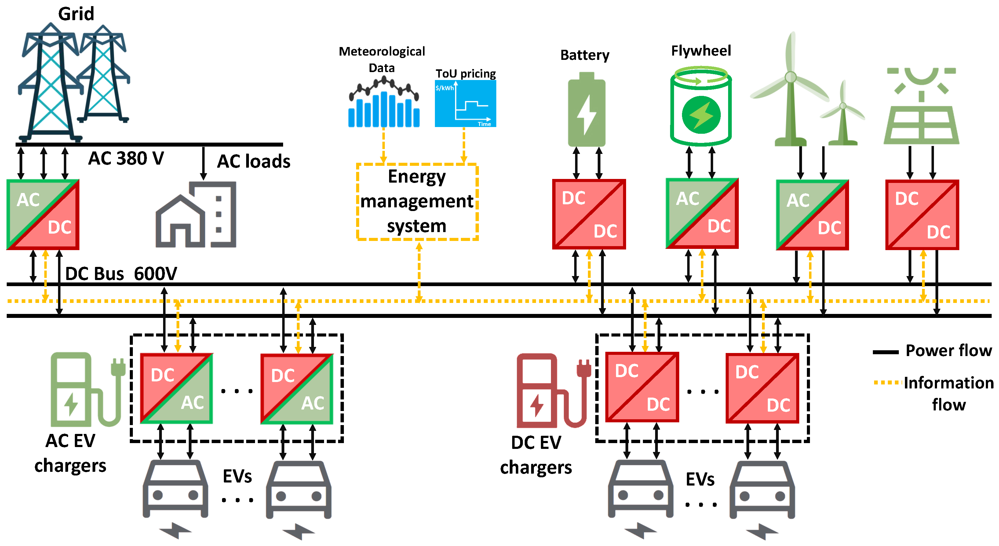
- Li, D.; Zouma, A.; Liao, J.T.; Yang, H.T. An energy management strategy with renewable energy and energy storage system for a large electric vehicle charging station. Etransportation 2020, 6, 100076. [Google Scholar] [CrossRef]
- Li, C.; Zhang, L.; Ou, Z.; Wang, Q.; Zhou, D.; Ma, J. Robust model of electric vehicle charging station location considering renewable energy and storage equipment. Energy 2022, 238, 121713. [Google Scholar] [CrossRef]
- Domínguez-Navarro, J.; Dufo-López, R.; Yusta-Loyo, J.; Artal-Sevil, J.; Bernal-Agustín, J. Design of an electric vehicle fast-charging station with integration of renewable energy and storage systems. Int. J. Electr. Power Energy Syst. 2019, 105, 46–58. [Google Scholar] [CrossRef]
- Shen, L.; Cheng, Q.; Cheng, Y.; Wei, L.; Wang, Y. Hierarchical control of DC micro-grid for photovoltaic EV charging station based on flywheel and battery energy storage system. Electr. Power Syst. Res. 2020, 179, 106079. [Google Scholar] [CrossRef]
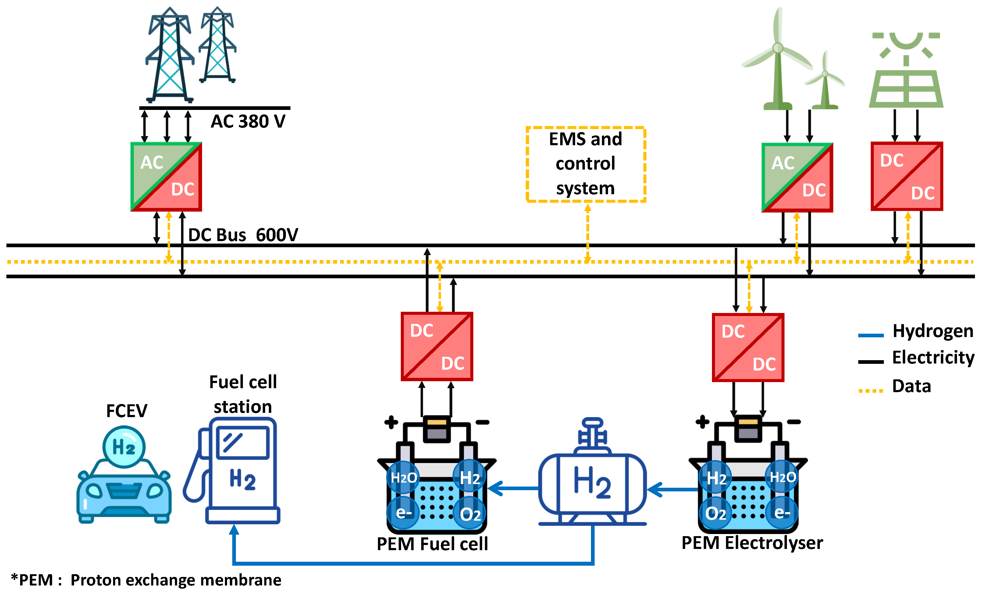
- Yue, M.; Lambert, H.; Pahon, E.; Roche, R.; Jemei, S.; Hissel, D. Hydrogen energy systems: A critical review of technologies, applications, trends and challenges. Renew. Sustain. Energy Rev. 2021, 146, 111180. [Google Scholar] [CrossRef]


| Symbol | Parameter | Value |
|---|---|---|
| Air density | 1.2 kg/cm | |
| Air penetration coefficient | 0.302 | |
| Vehicle cross-section | 2.4 m | |
| Rolling resistance coefficient | ||
| g | gravity acceleration | 10 m/s |
| Slope angle | ||
| M | Vehicle weight | 1500 kg |
| R | Radius of the drive wheel | 0.35 m |
| Wheels momentum of inertia | 4 kg·m |
| ICE Vehicles | Electric Vehicles | |
|---|---|---|
| Advantages |
|
|
| Drawbacks |
|
|
| Hybridization Level | Micro Hybrid (Stop/Start Hybrid) | Mild Hybrid | Full Hybrid/Plug-In Hybrid |
|---|---|---|---|
| Fuel consumption reduction in combined cycle | 3 to 10% | 15 to 25% | 30 to 40% |
| Installed electrical power | 2 to 6 kW | 10 to 20 kW | 20 to 60 kW |
| Battery voltage | 12 V to 42 V | 120 V to 150 V | 200 V to 300 V |
| Connectors | Charging Modes | Symbols | Country | Pins | Voltage, Current, Power | Standards |
|---|---|---|---|---|---|---|
| Type 1/j1772 | AC |  | USA Japan | 3 power pins (L, N, PE) | 120 V, ≤16 A, 1.9 kW 1 240 V, ≤80 A, 19.2 kW | SAE j1772 IEC 62196 |
| Type 2/Mennekes | AC |  | EU China | 5 power pins (L1, L2, L3, N, PE)
2 control signals–CP, PP (PWM for CP) | 1 230 V, ≤32 A, 7.4 kW 3 400 V, 63 A, 43 kW | IEC 62196 GB/T 20234.2-2015 |
| DC |  | Tesla (EU) | 3 power pins (DC+, DC−, PE)
7 control signals (comm. CAN) | 400 V, ≤140 A, 56 kW | IEC 62196 | |
| CHAdeMO (JEV G105-1993) | AC |  | Japan | 3 power pins (DC+, DC−, PE)
7 control signals (comm. CAN) | 200–500 V, ≤400 A, 200 kW CHAdeMO : 1000 V, ≤400 A, 400 kW | IEC 61851-23, -24 IEC 62196-3 IEEE TM-2015 |
| CSS/Combo | DC |  | USA | 3 AC pins
2 DC pins 2 control signals CP (PLC), PP | 200–1000 V DC, ≤350 A, 350 kW | IEC 62196-1/2/3 IEC 61851-1/22 IEC 61851-1/23 ISO/IEC 15118 DIN SPEC 70121 SAE |
 | EU | 5 AC pins
2 DC pins 2 control signals CP (PLC), PP | ||||
| GB/T | DC |  | China | 5 power pins (DC+,DC−,PE, 2 Aux. power pins BT
4 control pins: PP, CAN | 750/1000 V, ≤250 A, 237.5 kW | GB/T 20234 |
| Tesla | AC |  | Tesla (Except EU) | 3 power pins (DC+, DC−, E)
2 control signals CP, PP | 1 240 V, ≤72 A, 17.2 kW | IEC 62196 |
| DC |  | 3 power pins (L1, N, E)
2 control signals CP, PP | 400 V, ≤650 A, 250 kW |
| Specifications | 1 | 2 | 3 | 4 | 5 | 6 |
|---|---|---|---|---|---|---|
| Unidirectional battery charger | ✓ | |||||
| Bidirectional battery charger | ✓ | ✓ | ||||
| Bidirectional battery charger using the motor drive inverter | ✓ | ✓ | ✓ | |||
| Bidirectional battery charger using the motor drive inverter and electric machine winding | ✓ | ✓ | ✓ | ✓ | ||
| Bidirectional battery charger using multilevel modular converters | ✓ | ✓ | ✓ | ✓ | ✓ | |
| Contactless power transfer-based battery charger | ✓ | ✓ | ✓ |
Publisher’s Note: MDPI stays neutral with regard to jurisdictional claims in published maps and institutional affiliations. |
© 2022 by the authors. Licensee MDPI, Basel, Switzerland. This article is an open access article distributed under the terms and conditions of the Creative Commons Attribution (CC BY) license (https://creativecommons.org/licenses/by/4.0/).
Share and Cite
Amry, Y.; Elbouchikhi, E.; Le Gall, F.; Ghogho, M.; El Hani, S. Electric Vehicle Traction Drives and Charging Station Power Electronics: Current Status and Challenges. Energies 2022, 15, 6037. https://doi.org/10.3390/en15166037
Amry Y, Elbouchikhi E, Le Gall F, Ghogho M, El Hani S. Electric Vehicle Traction Drives and Charging Station Power Electronics: Current Status and Challenges. Energies. 2022; 15(16):6037. https://doi.org/10.3390/en15166037
Chicago/Turabian StyleAmry, Youssef, Elhoussin Elbouchikhi, Franck Le Gall, Mounir Ghogho, and Soumia El Hani. 2022. "Electric Vehicle Traction Drives and Charging Station Power Electronics: Current Status and Challenges" Energies 15, no. 16: 6037. https://doi.org/10.3390/en15166037
APA StyleAmry, Y., Elbouchikhi, E., Le Gall, F., Ghogho, M., & El Hani, S. (2022). Electric Vehicle Traction Drives and Charging Station Power Electronics: Current Status and Challenges. Energies, 15(16), 6037. https://doi.org/10.3390/en15166037