Review

Improvement of the Mechanical Characteristics, Hydrogen Crack Resistance and Durability of Turbine Rotor Steels Welded Joints

by
Alexander I. Balitskii
1,2,*,
Vitaly V. Dmytryk
3,
Lyubomir M. Ivaskevich
1,
Olexiy A. Balitskii
4,
Alyona V. Glushko
3,
Lev B. Medovar
5,6,
Karol F. Abramek
2,
Ganna P. Stovpchenko
5,6,
Jacek J. Eliasz
2 and
Marcin A. Krolikowski
2
1
Department of Strength of the Materials and Structures in Hydrogen-Containing Environments, Karpenko Physico-Mechanical Institute, National Academy of Sciences of Ukraine, 79-601 Lviv, Ukraine
2
Department of Mechanical Engineering and Mechatronics, West Pomeranian University of Technology in Szczecin, 70-310 Szczecin, Poland
3
Welding Department, National Technical University «Kharkiv Polytechnic Institute», 61-000 Kharkiv, Ukraine
4
Adolphe Merkle Institute, University of Fribourg, Chemin Des Verdiers 4, 1700 Friborg, Switzerland
5
Department of Physical and Metallurgical Problems Electroslag Technologies, E.O. Paton Electric Welding Institute, National Academy of Sciences of Ukraine, 03-150 Kyiv, Ukraine
6
Private Engineering Company ‘ELMET-ROLL’, P.O. Box 259, 03-150 Kyiv, Ukraine
*
Author to whom correspondence should be addressed.
Energies 2022, 15(16), 6006; https://doi.org/10.3390/en15166006
Submission received: 20 July 2022 / Revised: 11 August 2022 / Accepted: 16 August 2022 / Published: 18 August 2022

Abstract

:
This article is devoted to the following issues: calculating the values of temperatures obtained by simulating welding heating and the subsequent implementation of the welding process at the given mode parameters made it possible to obtain a welded joint of the rotor with an improved initial structure and increased mechanical properties, hydrogen resistance and durability by up to 10–15%; simulating welding heating in the areas of fusion, the overheating and normalization of the HAZ and the formation of austenite grains; specified welding heating creates the conditions for the formation of new products of austenite decomposition in the form of sorbitol in the area of the incomplete recrystallization of the HAZ. In air and gaseous hydrogen, the destruction of the combined joints took place on the weld metal, as well as on the fusion areas, the overheating and the incomplete recrystallization of the HAZ of 20H3NMFA steel as the base metal. Structural materials have a relatively low strength and high fracture toughness in air. This is manifested in a significant reduction in the elongation (δ), the area (ψ) and critical stress intensity factor (KIc) of welded joints and the endurance limit of cylindrical smooth rotor steel specimens, which were cut from transverse templates. Welded joints in the whole range of load amplitudes are sensitive to the action of hydrogen.

1. Introduction

Modern requirements for the operation of the United Electric Power System (UEPS) of Ukraine and the Polish Power System (PSE S.A.) (main activity: provide the services of electricity transmission in compliance with the required criteria of the security) with a tendency to major “green” electricity are quite high. The reliability of work and the increase in the power plant turboaggregate (TA) service life are the priority tasks [1]. They are operated in harsh conditions determined by high temperatures and stresses, which lead to irreversible changes in the properties of the metal and damage to the steel weldments [2,3,4,5,6,7,8] (Figure 1 and Figure 2).
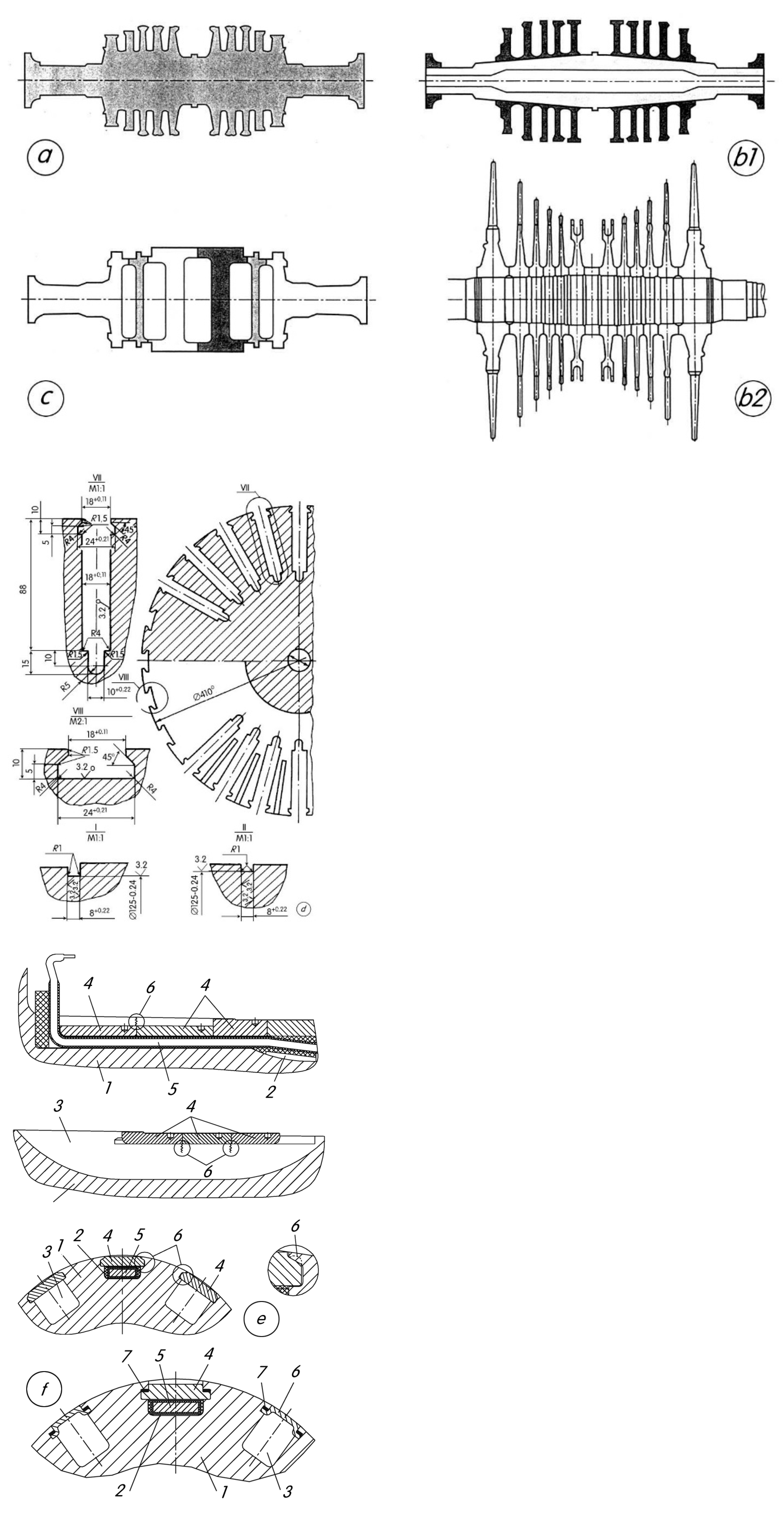
Turbogenerator (TG) rotor shafts (Figure 3d) are a complex engineering structure with numerous structural stress concentrators both on the rotor barrel and on its tail. The materials used for the manufacture of such TG assemblies must have sufficient strength and ductility during all TA operating modes [2,3]. So, investigating the heat transfer on the surface and inside TA elements, the stress-strain behavior and influence of hydrogen-containing environments and mechanical loading, the methods of enhancement of cooling media heat transfer, the manufacturing of heat exchangers and other components under mechanical and thermal loading is very useful, because the steam and hydrogen turbine rotors have limited the lifetime of TA.

2. Literature Survey: State of the Art

The steel for shaft and rotor blanks is smelted in open-hearth furnaces with acid lining or electric furnaces. Vacuuming must be used when pouring ingots weighing more than 25 t. According to [2,3,4,5], for the manufacture of shafts and rotors of steam turbines and TG in Ukraine, Poland and other countries, it is recommended to use special grades of steel with the appropriate chemical composition, depending on the strength category. The length of the rotor shafts can reach 13.4 m, and the diameter can reach 1.8 m with a total mass of about 160 t (for the mass of the output ingot over 360 t).
Only the part of the ingot that has the most homogeneous material is used to make the rotor. Magnetic and ultrasonic flaw tests, together with the study of the mechanical properties of the samples obtained by radial and axial drilling and the careful control of the structure, allow for the selection of the necessary material for the rotor. Along with the promising open-hearth method of manufacturing powerful TG rotors, there is the electroslag welding of two workpieces.
The need to develop a new method is associated with the prospect of developing TG for power plants with a capacity of up to 2000 MW. In this case, the diameter of the rotor will approach 3.0 m, and the mass of the rotor shaft can exceed 300 t (respectively, the forging for the manufacture of such a shaft will weigh more than 400 t, and the total weight of the steel ingot is about 680 t).
Therefore, the search for non-traditional methods of manufacturing shafts and rings from electroslag steel for high-speed (3000, 3600 RPM) and low-speed (1500, 1800 RPM) powerful TG and related turbines continues.
At the same time, manufacturers are improving existing technologies for the manufacture and reliable operation of rotors. The parameters that determine the operating conditions of the contact of the wedges with the shaft for TG vary widely. In particular, the nominal bending stress in the shaft varies from 16 … 19 (TVV-320-2) to 29 … 33 MPa (TVV-1200-2), and the average contact pressure varies from 85 (T3V-800-2) to 300 … 305 MPa (TVV-1200-2, current supply groove). The durations of rotor operation before the appearance of developed cracks also differ—from (2 … 3) × 107 cycle (TVV-1200-2) to (2 … 3) × 1010 cycle (TVB-320-2). For TG type TVV-220-2, the operation duration (5 … 8) × 1010 cycle [2,3,4] in gaseous hydrogen (used for cooling technology) can be the base for the materials selection for hydrogen turbine rotors.
Low-alloy steels with a typical carbon content of 0.2 … 0.3% are mainly used for steam turbine rotors in EU and the USA. The standard heat treatment of these steels includes austenitization, hardening and tempering at temperatures above 600 °C, which results in a bainite microstructure with a yield strength of 800 MPa [2,3,4,5,6,7,8,9,10,11,12,13,14,15,16,17,18,19,20,21,22,23,24,25,26,27,28,29,30,31,32,33,34].
The operating time of most of the NPP power units has already exceeded its park resource [25,26,27,28,29,30,31,32,33,34]. Thus, the priority direction of research is to increase the reliability and extend the service life of the operation of power units, including the components of power units.
The increase in operational requirements for the rotors of high-power steam turbines at nuclear power plants necessitates improving the quality characteristics of the initial metal structure of their welded joints, which is characterized by the presence of a certain heterogeneity. It is advisable, by using the optimal welding heating of the manufactured joints, to reduce the level of the initial structural heterogeneity, which increases with an increase in their operating time [25,26,27,28,29,30,31,32,33,34].
In the process of the formation of the initial structure of welded joints, structures can be formed (locally) in it, which can be conditionally referred to as rejection ones. Such rejection structures contribute to the accelerated damage of the metal of the welded joint of the rotor during its operation under fatigue conditions, which causes a decrease in its reliability and a decrease in its resource.
The goal of this work is to simulate the welding heating of the manufactured joint of the steam turbine rotor made of 25H2NMFA and 20H3NMFA steels to obtain the initial structure of the welded joint with an improved quality of mechanical characteristics and crack resistance in hydrogen-containing environments.

3. Formulation of the Problem: Materials and Methods

For the manufacture of forged billets of welded turbine rotors (for example, K-1000-60/1500 and its modifications, K-1000-60/1500-2, etc.), 25H2NMFA steel is used. Blanks for welded rotors are subject to the individual determination of mechanical properties using special quality control methods for their metal.
In the energy sector, the trend of using powerful steam [2,3] and promising hydrogen [4] turbines with a combined rotor, which is obtained by welding, is becoming relevant [1]. This rotor is operated in high- and low-temperature modes. The combined rotor is made of alloy steels that meet the special operating conditions of high-pressure (HP), medium-pressure (IP) and low-pressure (LP) cylinders. For the stages of the rotor, which operates in low temperatures at JSC “Turboatom”, the steels 25H2NMFA and 20H3NMFA were proposed [10,11,12,13,14,15].
For stages operating in the temperature range close to 500 °C, the steel 25H2NMFA was proposed. This steel has relatively high mechanical properties but is difficult to weld.
The welding of the 25H2NMFA and 20H3NMFA steels (Table 1) is an extremely difficult task [10,11,12,13,14], which is associated with the formation of defective structures in the alloying area, as well as in the area of incomplete recrystallization of the heat-affected zone (HAZ) of the 20H3NMFA steel welded joint. An urgent requirement is also to ensure the necessary resistance against the formation of cold cracks.
The SV08HN2GMYu electrode wire with a diameter of 2.0 mm and AN-43M flux was used for the experiments, which ensured the achievement of the optimal composition in the weld metal of the alloying elements and also limited the presence of harmful impurities of sulfur and phosphorus (Table 1).
The restriction of sulfur and phosphorus prevented the metal from crumbling to weld, which occurs after high tempering.
The welding of the rigid technological samples was performed on the mode: Iweld = 300 … 320 A; Uweld = 34 … 36 V; Vweld = 18 m/h. Control over the formation and growth of cracks was performed using acoustic emission signals. It was established that cold cracks are formed in the weld metal during the welding of technological samples without preheating. Their origin, as shown by acoustic emission signals, begins immediately after welding and continues with the imposition of subsequent rollers.
The resistance to failure of 20H3NMFA welds in unheated welding was relatively low, but when heated to 300 °C, such indicators become satisfactory. Thus, to ensure a high resistance to the slow destruction of welded joints of the steels 25H2NMFA and 20H3NMFA, obtained by automatic submerged arc welding, it is possible to recommend the pre-heating and concomitant heating of samples in the temperature range of 250 … 300 °C.
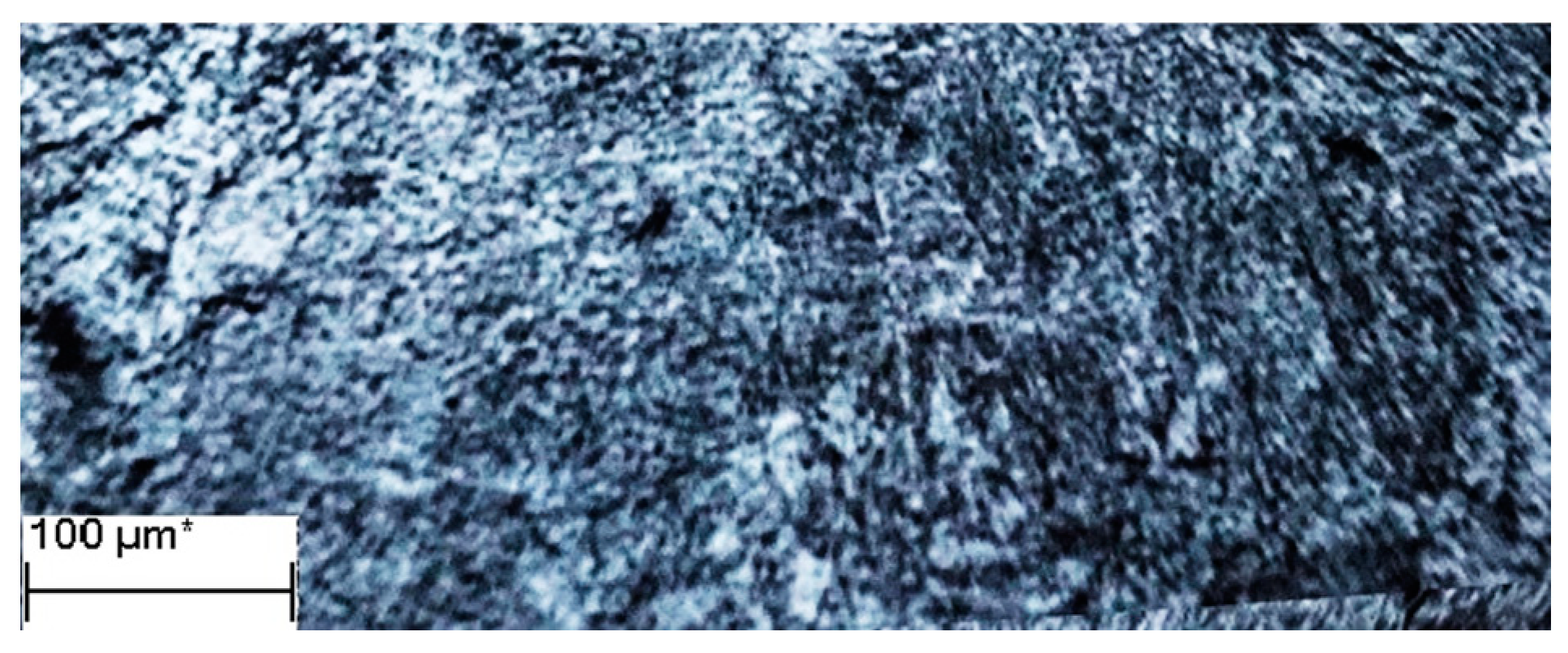
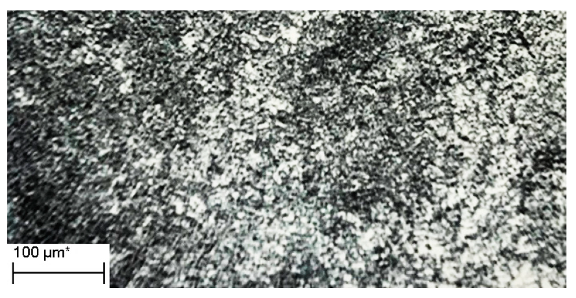
The proposed technology, as shown by metallographic studies (Figure 4), allowed for the obtention of welded joints with relatively high mechanical properties, without cracks and tears.
The use of wire, as well as the above modes of welding, provided the structure of the weld metal in the form of bainite with carbides. This structure is not prone to slow destruction, which is ensured by the absence of the local microplastic deformation of its structural components.
The determination of the mechanical properties was performed on samples cut from weld metal, as well as from combined welded joints of the steels 25H2NMFA and 20H3NMFA, the thickness of which was 80 mm. Welding was performed according to the above modes. Welded joints were subjected to high tempering at 620 °C for 30 h.
It was found that the strength and ductility of the welded joints at 20 °C and 450 °C (operating temperature) are relatively high and meet the regulatory requirements (Table 2). The toughness of the weld metal is slightly lower than that of the base metal, which was not affected by welding heat (Table 2 and Table 3). The critical temperature of fragility is in the region of low temperatures (−15 °C … −10 °C).
The metallographic analysis of the structure of combined welded joints showed that the metal of HAZ sections has a mainly sorbitol and bainitic-ferritic structure on the 25H2NMFA side, as well as a bainitic martensite structure on the 20H3NMFA side [10,11,12,13,20].
The weld metal is characterized by the presence of a bainitic-ferritic structure. Measurements of the hardness of the metal of the combined weld showed that the structures in the area of overheating on the side of the 20H3NMFA steel have a hardness of HV 350 … 360, and in the area of overheating of the 25H2NMFA steel, they have a hardness of HV 300 … 320.
The base metal, which has not undergone welding heat, has a hardness of HV 280 … 290 (steel 20H3NMFA) and HV 230 … 240 (steel 25H2NMFA). After tempering at 620 °C (20 h) the structure of the welded joints acquires alignment, and the hardness is HV 180 … 190.
In the area of the fusion of the weld metal with the steel 25H2NMFA, the hardness decreases to HV 160 … 170. In the area of the fusion of the weld metal with the steel 20H3NMFA, the hardness is slightly higher than HB 190 … 205.
The hydrogen content in the metal of the ingots should not exceed 2.23 ppm [10,11,12,13,14,15], and the decrease in its value in steel and weldments has led to the improvement of the mechanical characteristics, hydrogen resistance and durability of steam turbine rotor steels welded joints. The initial steel structure is tempered bainite (Figure 4).
The study of the structural state of welded joints made of 25H2NMFA steel, as well as of steels with a similar chemical composition [6,10,11,12,13,14], showed that rejection structures or structures close to rejection ones can form in the metal of welded joints. For example, it is still an urgent task to obtain fine austenite grains in the areas of the heat-affected zone (HAZ) of welded joints: fusion, overheating and normalization. A significant contribution to the practical and theoretical solution of the problem of obtaining a fine-grained austenitic structure was made in [6,10]. However, his work could not lead to a solution to the problem of preventing the formation of large austenite grains in thick-walled welded joints.
Welding heating (standard technology) provides a long stay of fusion, overheating and normalization of the HAZ of the studied thick-walled welded joints in the temperature range Ts-950 °C, which leads, accordingly, to the formation of large austenite grains. Long-term heating to the temperature range AC1–AC3 leads, in the area of the incomplete recrystallization of the HAZ, to the formation of new products of austenite decomposition in the form of globular pearlite [11,12,13,14]. In the samples, after welding, a significant increase in hardness was revealed, corresponding to the areas of fusion and overheating of the HAZ [11,12,13,14]; however, they did not explain the relationship between the increased hardness and the structural state of the areas.
The presence of the above structures reduces the resistance of the metal of welded joints to brittle fracture from the action of centrifugal forces, stress corrosion, hydrogen cracking and fatigue damage under the action of alternating stresses during rotation, bending and torsional vibrations.
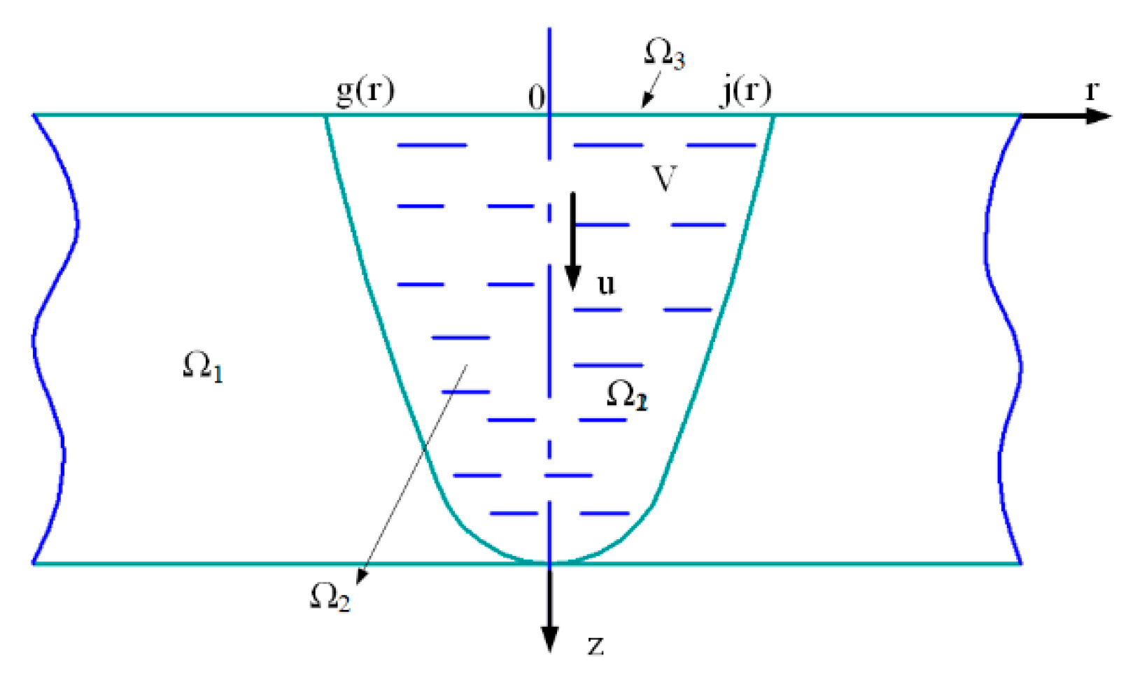
The improved thermal problem [11,12,13,14], applied to the welded joint of the rotor (Figure 5), was solved in a joint delivery under the conditions of the Navier–Stokes (molten metal of the weld pool) and Fourier (base metal, as a solid phase) laws (Figure 6).
The solution was carried out in a cylindrical coordinate system in an axisymmetric setting. It was assumed that a quasi-stationary process of heat transfer and crystallization takes place.
Let us write the Navier–Stokes Equation (1):
{ ξ t + 1 r ψ r ξ z 1 r ψ z ξ r + 1 r ψ z ξ r = = V [ 1 r r ( ξ r ) + 2 ξ z 2 ξ 2 r ] + g β T r + ( j × B ) z ( 1 r ψ z ) + r ( 1 r ψ r ) + ξ = 0 T t 1 r ψ z T r + 1 r ψ r T z z = = 1 ρ c [ 1 r r ( k r T r ) + z ( k T z ) + Q k ]
Here, υ = μ/ρ is the kinematic viscosity; g—acceleration of gravity; vector = r e z + z e r . The mixed product ( j × B ) determines the influence of electromagnetic forces on the behavior of the dynamics of flows of liquid metal in the molten bath; B is the magnetic field strength; β is the coefficient of thermal expansion; T is the temperature; ψ is the melt flow function; ξ—coordinate of the rotor of the velocity field; ρ, s, μ, k—density, heat capacity, dynamic viscosity and thermal conductivity; Qk—additional heat input into the bath melt.
Let us introduce the stream function of the molten metal ψ and the vortex ξ. The relationship with physical variables will be as follows:
ξ = ν z u r ; u = 1 r ψ r ; V = 1 r ψ z
According to the approximation, System (1) is written in the Form (3):
{ Ω [ ψ r ξ z ψ z ξ r + ψ z ξ r ] φ k d r d z + + ν Ω [ ( ξ r φ k + r φ k r + ξ φ k r + ξ z φ k r r ) ] φ k d r d z + + g B Ω T ( φ k + r φ k r ) φ k d r d z = Ω π ( j × B ) φ k d r d z Ω [ ψ z φ k z + 1 r φ k r ( φ k + r φ k r ) + ξ φ k r ] φ k d r d z = 0 Ω [ ( ψ z T r + ψ r T x ) + k ρ C p ( T r φ k r + T z φ k z ) ] φ k d r d z = = Ω Q k φ k d r d z , ( k = 1 , , n )
φk are basis functions, which were determined by the method of R-functions.
The free surface of the molten bath Ω3 (Figure 6) was taken as flat. With regard to the weld pool, a joint solution of the nonlinear system of equations of the magnetohydrodynamics of the motion of molten metal as a viscous liquid, the system of Maxwell’s equations for the distribution of the vectors of strength of the electric and magnetic components of electromagnetic fields, was performed. With regard to the base metal, as a solid phase, to determine the values of temperatures T, the nonlinear equation of thermal conductivity was solved. System (3) was formulated as a problem as applied to phase transitions with a free boundary, which corresponds to the conditions of the Stefan problem.
In the calculations of the temperature regime in welded joints, the traditional scheme (which coincides with the Ritz method) was used; in this case, the basis functions were constructed in spatial variables, and the motion in time was taken into account using the Rothe method, i.e., by sampling in time. This method made it possible to reduce the system of non-stationary Navier–Stokes equations to a system of stationary equations. The solution of the last system was carried out in an iterative way, in which the k + 1 approximation includes the k-th approximation as the initial one.
By choosing a system of basis functions {φ} in the form of splines (the classical method), we projected the resulting expansion of solutions into an n-dimensional subspace. In this case, the time for calculating all the integrals that are included in the matrix of the system of linear Navier–Stokes equations is significantly reduced. With the optimal selection of the initial basis functions (taking into account the experimental data), fairly accurate results were obtained already on the first few terms of the expansion.
The solution to the heat problem allowed:
1. For the establishment of the temperature regime of the welding process, ensuring the formation of a given structure of the welded joint;
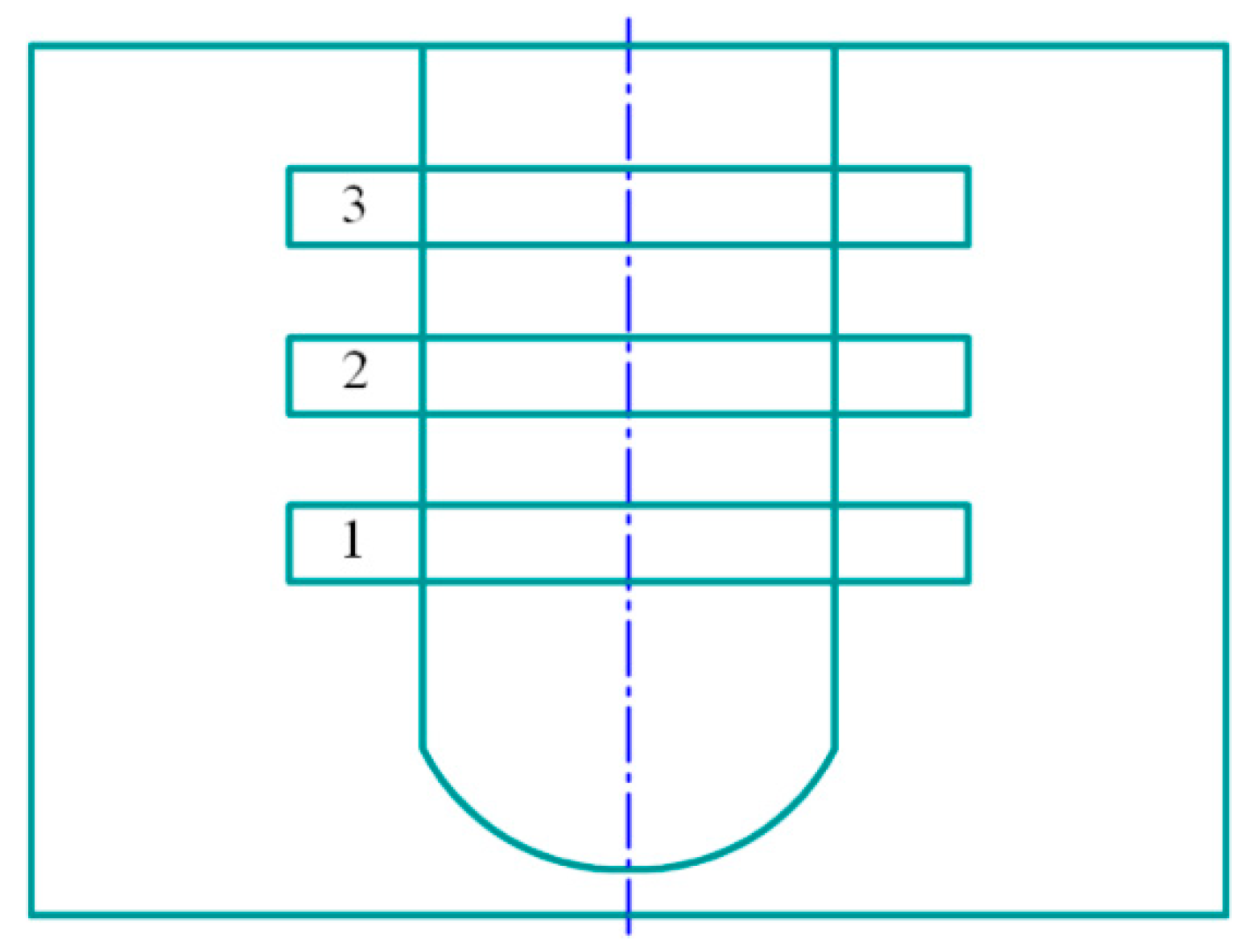
2. For the revelation, in the weld metal and in the area of HAZ fusion, of the places of local welding overheating, where structures can form as rejection ones or as structures that can be referred to as rejection ones. For example, large austenite grains in the areas of fusion, overheating and normalization of the HAZ and new products of austenite decomposition in the form of globular pearlite in the area of incomplete recrystallization. It was found that the reduced structures can form mainly in the central zone of the welded joint (see Figure 5 and Figure 7) (Samples 1–3). Note that the simulation of welding heating allows, in a practical way, for the prevention of the formation of both rejection structures and structures that can be attributed to rejection [6].
The use of numerical data characterizing the temperature regime of welded joints made it possible, taking into account the known techniques [15,16,17,18,19,20,21,22,23,24,25,26,27,28,29,30,31,32,33,34,35], to optimize the parameters of the automatic welding regime. Then, the welding process of the prototype witness was carried out on the optimized parameters: welding current 390–420 A; arc voltage 38–40 V; welding speed 20–25 m/h; electrode wire feed speed 125–130 m/h; diameter of the electrode wire 2.0–2.5 mm.
The mode parameters during the welding process were changed within the recommended values. Their change was caused by the need to obtain an optimized temperature regime that ensures the formation of a given structure.
The preliminary and concomitant heating of the prototype to be welded was 300–350 °C. Immediately after welding, the sample was subjected to high tempering T = 630–650 °C, lasting 130–150 h. Then, from the witness sample (Figure 5), templates were cut out to study the structure and properties (Figure 7).

4. Results and Discussion: Weldments Structure and their Mechanical Properties

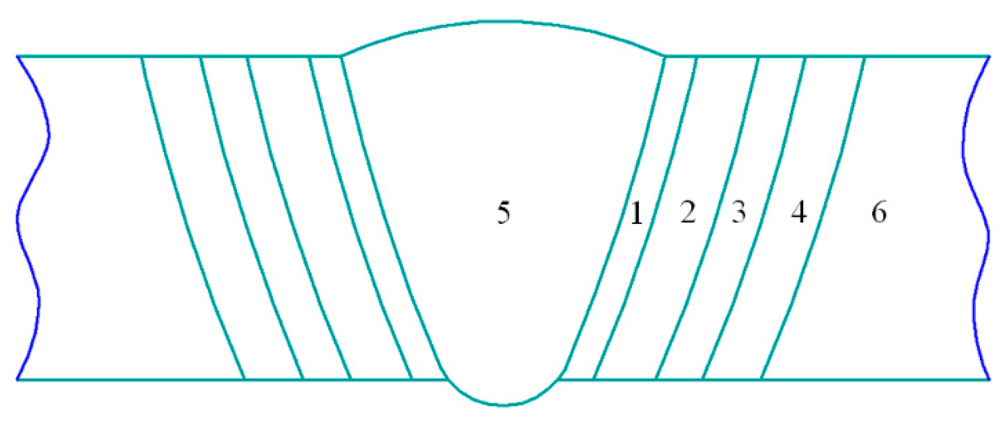
The application of the famous method, when solving the heat problem, made it possible to construct smoothly-approximated temperature isotherms (Figure 8 and Figure 9), which made it possible to restrict the HAZ sections with the same structure in the welded joint.
The calculated and experimental data characterizing the regions of the formation of the corresponding structures were compared with the data of the thermos-kinetic diagram of the steels 25H2NMFA and 20H3NMFA. The comparison, as well as taking into account the known results [22,23,24,25,26,27,28,29,30,31], made it possible to improve the mathematical model of welding heating of the manufactured rotor and to refine the numerical data characterizing the thermal cycle.
The widths of the HAZ sections on the templates (Figure 4) were determined by taking into account the presence of similar structures in the areas. The separation of differing structures in relation to the corresponding sections of the HAZ was marked with reference points. The study of the structural state of the welded joint made it possible to reveal the width of the HAZ sections (Figure 5).
Template 1: fusion area 0.1–0.12 mm; overheating area 3.0–3.1 mm; area of incomplete recrystallization 2.4–2.6 mm. Template 2: fusion area 0.11–0.13 mm; overheating area 3.2–3.3 mm; area of incomplete recrystallization 2.6–2.8 mm. Template 3: fusion area 0.1–0.11 mm; overheating area 3.1–3.2 mm; area of incomplete recrystallization 2.5–2.7 mm.
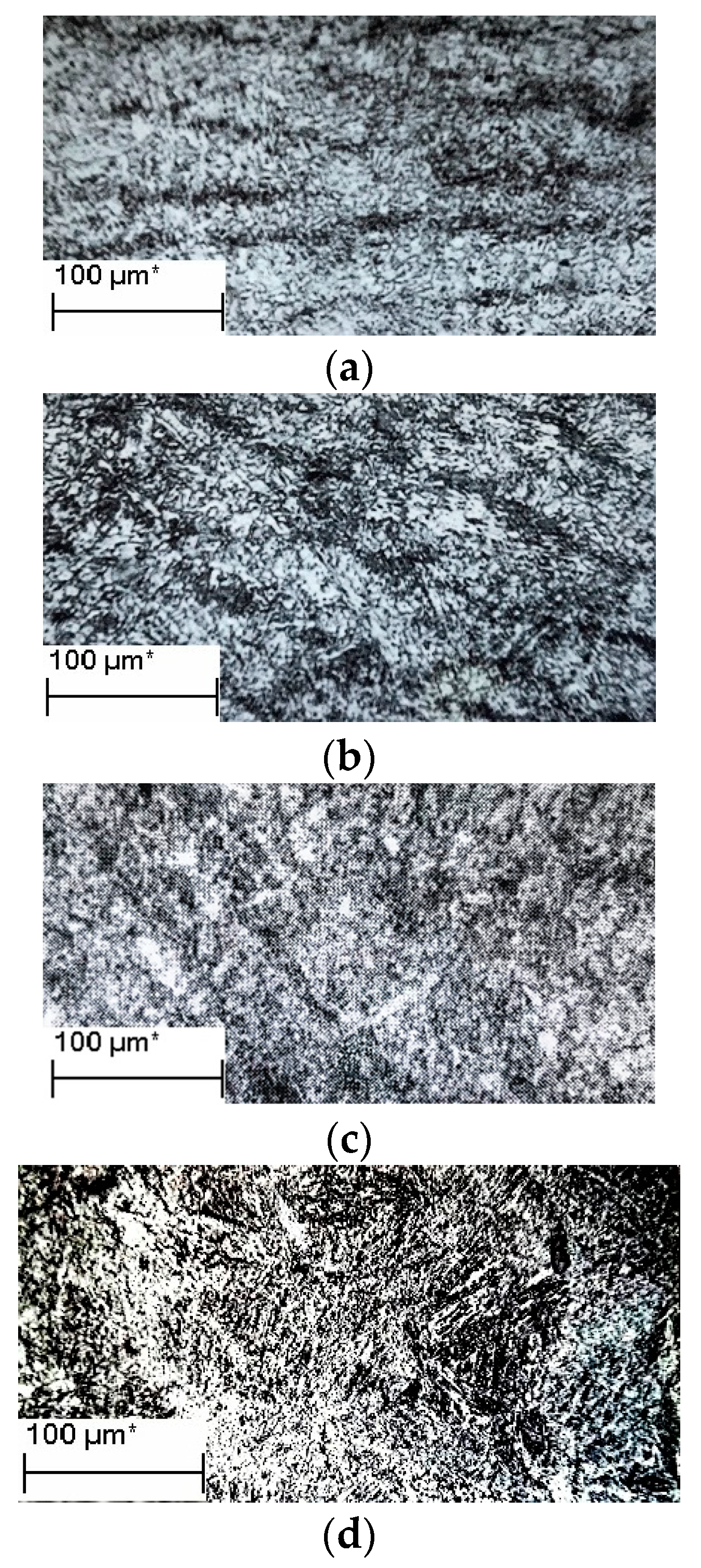
Seam metal (Figure 4 and Figure 6, Template 1) has a bainitic structure with sorbitic components oriented in accordance with the temperature regime providing their directional formation.
On template 2, the structure is presented as bainite-troostite with sorbite inclusions with a locally thickened character. On template 3, the structure is also bainite-troostite with a small amount (about 8%) of the ferrite component.
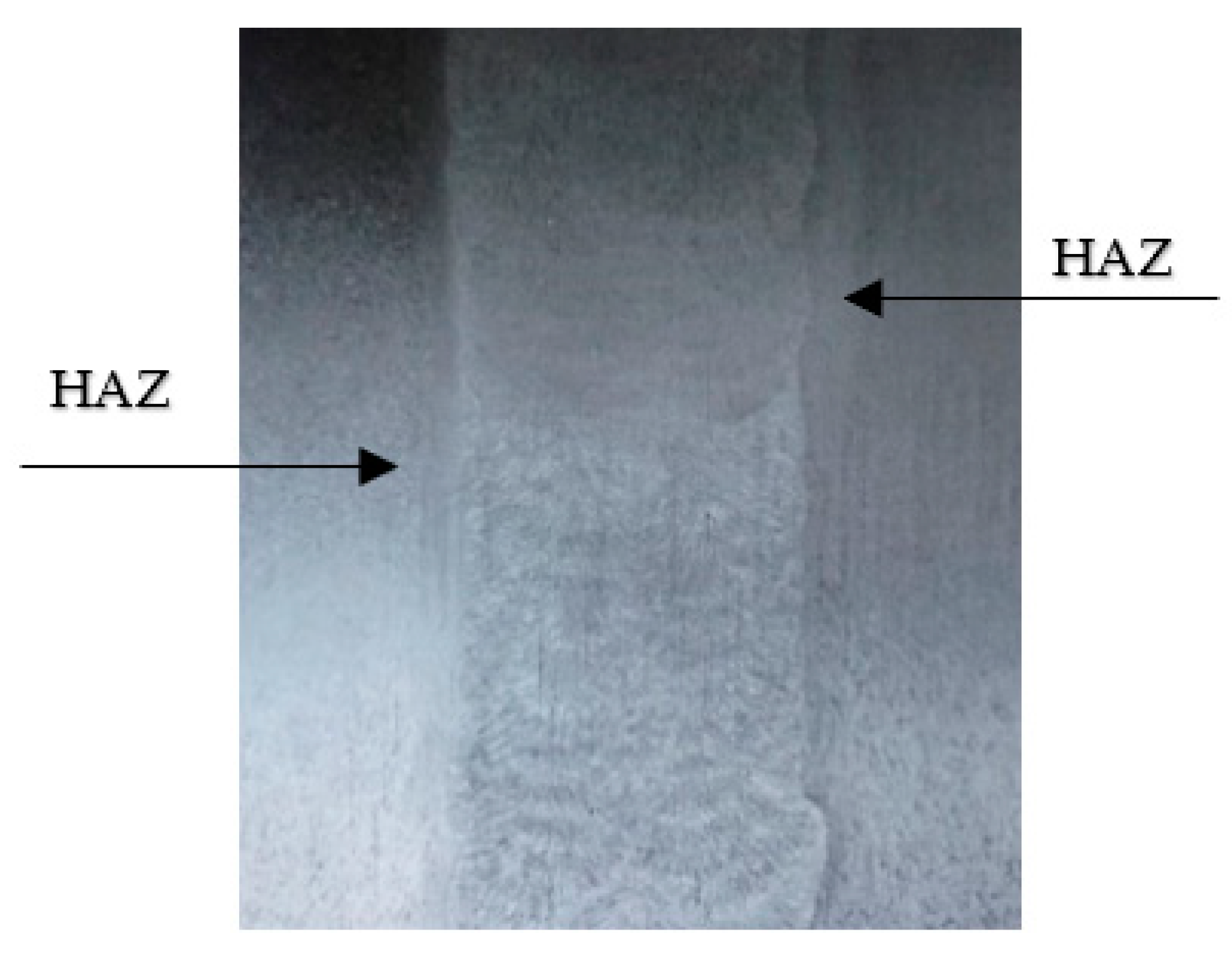
In the fusion area of HAZ (Figure 10), there is a smooth transition between the structure of the weld metal and the base metal. The structure of the fusion area is characterized by the presence of fine grains in a dark matrix. There are precipitates of the cementite type in the form of rounded, finely dispersed inclusions, the arrangement of which along the body and along the grain boundaries of the α-phase is close to uniform. The structural heterogeneity of the fusion area meets the regulatory requirements.
The overheating section (Figure 11 (template 2, Figure 7 and Figure 8)) has a predominantly sorbate-troostite structure.
Austenitic grains in the areas of fusion and overheating correspond to No. 7–No. 9. Accordingly, the largest grains are noted on template 2 (see Figure 11). Smaller ones are noted on templates 1 and 3. It was revealed that the matrix phase in the areas of fusion and overheating of the HAZ is bainite, which is close to granular in shape. The formation of bainite in the process of post-weld cooling occurs mainly by the martensitic mechanism.
The structure of the area of incomplete recrystallization of the HAZ (Figure 12) represents temper bainite with sorbitol constituents (dark grains in bainite).
Sorbitol constituents are the new decomposition products of austenite. It was found that M3C carbides in the structure of the HAZ sections and in the weld metal structure are distributed mainly evenly. The grain size of the α-phase under tempering conditions does not undergo changes. The coagulation of carbides of the first group (M7C23, M23C6) is insignificant, and in the second group, Mo2C, it is absent.
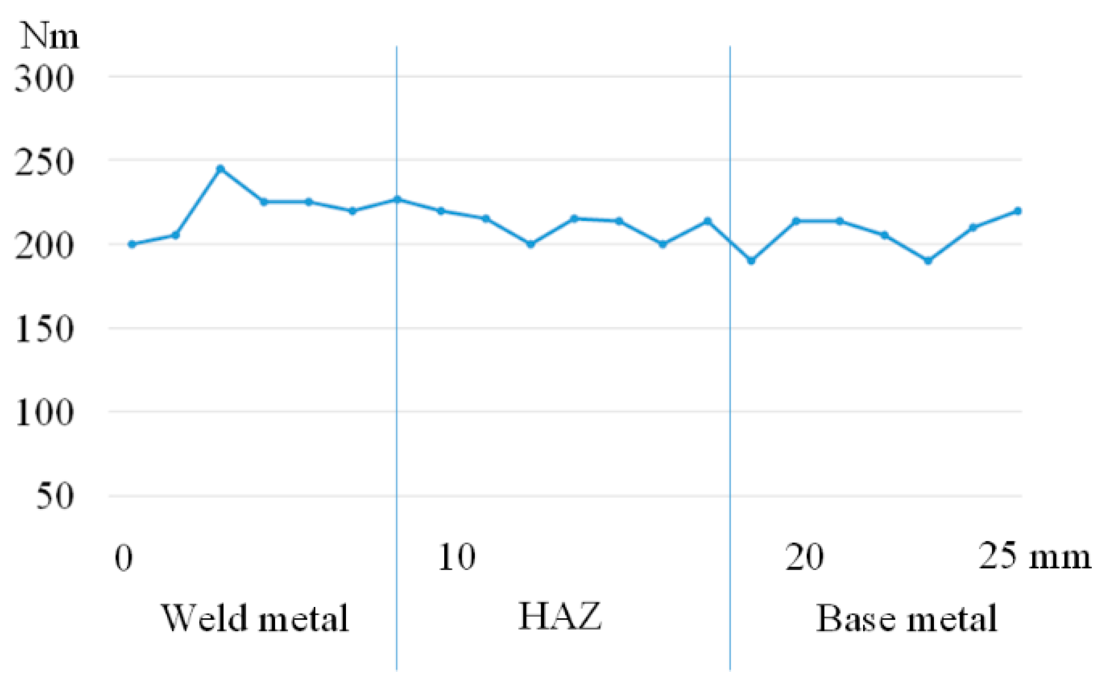
It was found that the amount of retained austenite (7–9%) in the weld metal, which turns into a ferrite-carbide mixture during tempering, does not significantly affect the mechanical properties, which is confirmed by the microhardness values (Figure 13).
The presence of the considered structures in the metal of the welded joint is also confirmed by the value of the microhardness.
It was found that the specified welding heating ensures the formation of smaller austenite grains in the HAZ sections, which is confirmed by the values of the impact toughness increasing by 10–15% in comparison with the similar values of the samples manufactured using the standard technology.
It was found that the average short-term mechanical properties of welded joints (see Figure 7) exceed the regulatory requirements by 5–10%: σB 680 N/mm2; σ0.2 520 N/mm2; δ 25%; ψ 63%; KCV 187 J/cm2; HB 197.
The study of the welded joints’ structure has shown that high tempering in the weld metal provides a transition from α-phase crystals to chromium and molybdenum carbides, as well as the formation of new carbides: M7C23, M23C6 and Mo2C. The value of the critical point AC1 decreases by 32–35 °C in comparison with the base metal that does not undergo welding heating. The value of the temperature of the AC3 point of the base metal, in comparison with similar values, does not change noticeably. The density of dislocations in the crystals of the α-phase after tempering decreases by about 10–15% and amounts to 2.15 × 109 cm2 in the fusion area, 1.9 × 109 cm2 in the overheating area and 1.7 × 109 cm2 in the base metal.

5. Weldments’ Static Crack Resistance in Hydrogen

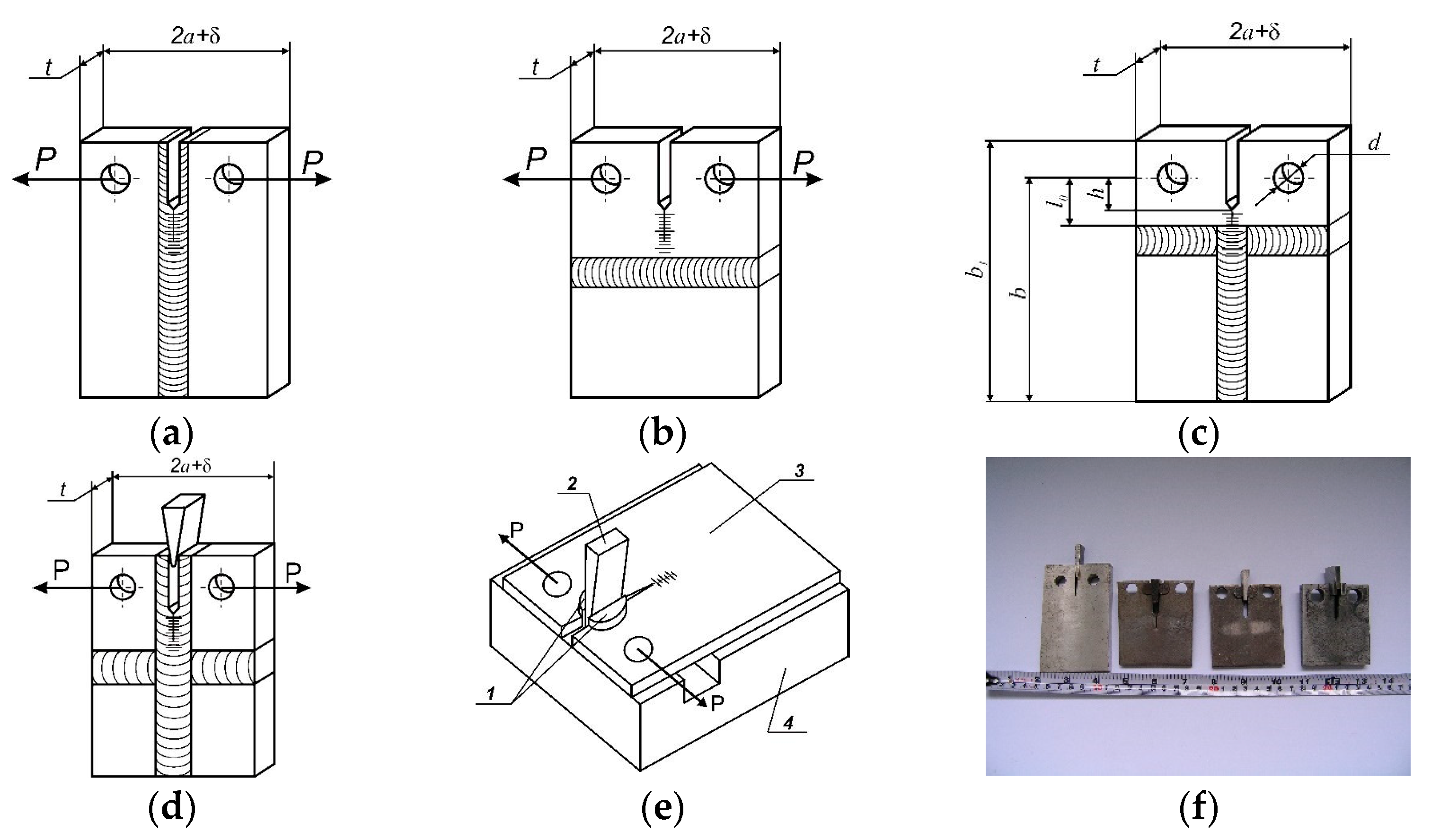
Compact specimens with welds, which provide controlled propagation of the main crack on the metal of different zones of the weld (Figure 14 and Figure 15) [35,36,37,38,39,40], effectively contribute to the optimization of welding modes.
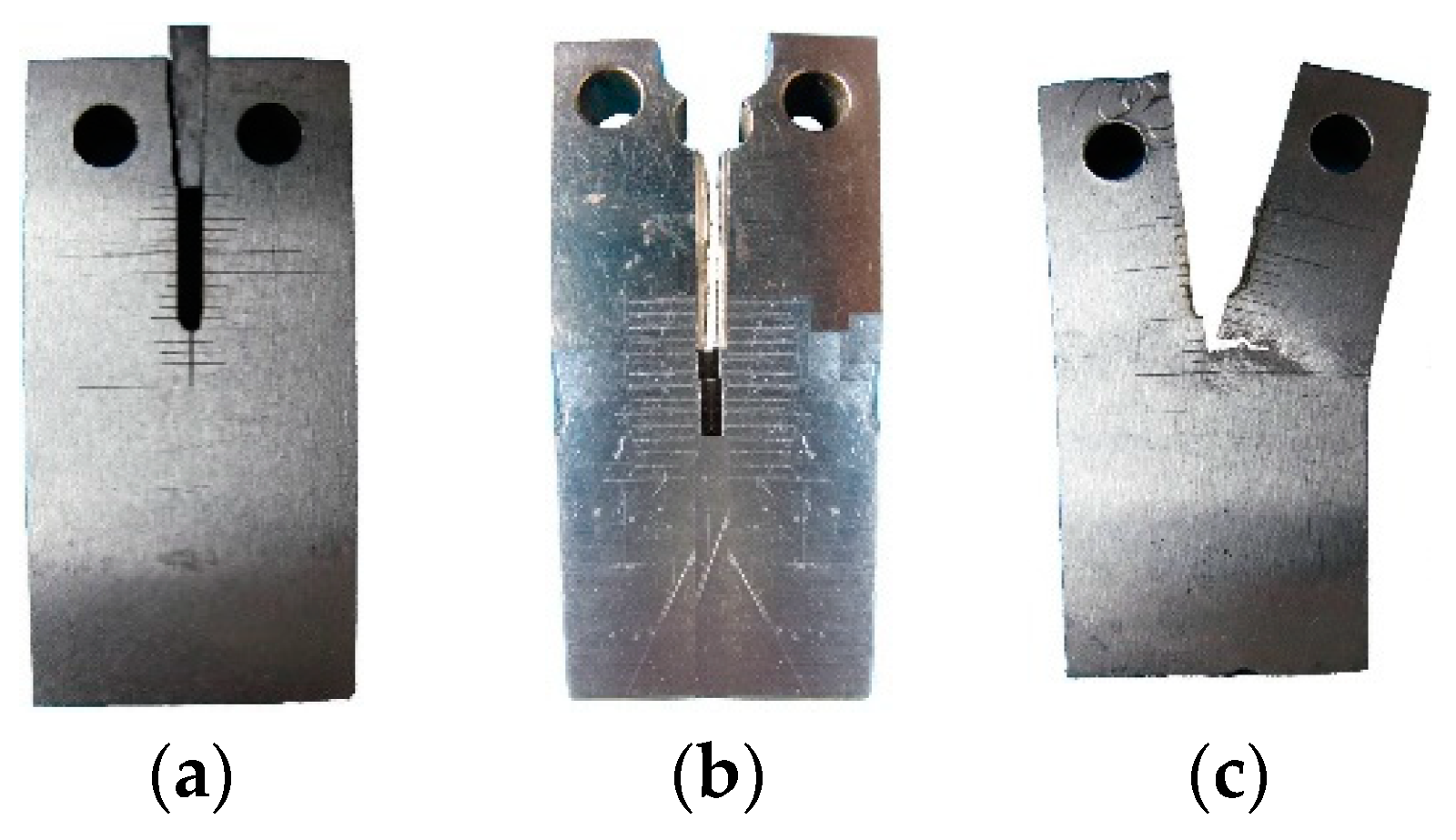
The disadvantage of the model in the case of welded joints of different configurations is that, in the process of spreading cracks along the entire length of the part, welds can serve as traps for cracks, and this changes their trajectory (Figure 16), sometimes at an angle up to 90° (Figure 16). This phenomenon is due to the occurrence of stress concentrators in the remelting areas, which negatively affect the performance characteristics, particularly crack resistance. During welding, microcracks appear near the fusion line, which cause a decrease in compressive residual macro stresses. All of this also negatively affects the performance of machine parts under cyclic and static loads during long-term operation.
Uneven grain sizes, the sizes and distribution of reinforcing phases, local thermal stresses and other defects cause the significant sensitivity of various structural elements of welded joints to the action of hydrogen [41,42,43,44,45,46]. Even the simulation of the soldering regime with the short-term (15 min) heating of KhN43MBTYu and 05Cr19Ni55 alloys to 1473 K leads to an increase in grain size and the concentration of large grain boundary intermetallic precipitates, which significantly enhances the hydrogen embrittlement of materials [47,48]. In the presence of hydrogen, the mechanical characteristics of welded joints deteriorate—short-term strength and ductility [43,44] and low-cycle durability [44,45].
Important characteristics of critical structures, including steam and hydrogen turbine rotors, are the parameters of crack resistance [49,50,51,52,53,54,55,56,57,58,59,60,61,62,63,64,65,66,67,68,69,70,71,72,73,74,75,76,77,78,79,80,81,82,83,84,85,86,87,88,89,90,91,92,93,94,95,96,97,98,99,100,101,102,103,104,105,106,107,108,109,110,111,112,113,114,115,116,117,118], which are also significantly reduced by hydrogen [41,42,46,47,48,53,54,55,56] with a pressure up to 10 MPa. Given the variety of factors that determine the properties of welded elements in hydrogen-containing environments, to assess their performance requires the experimental determination of a set of physical and mechanical properties of a particular joint [119,120,121,122,123,124,125], especially for the structural elements of the hydrogen energy buffer (electrolizers, fuel cells, hydrogen storage and grid distribution), with the intention of utilizing hydrogen and the accompanied phenomenon of their hydrogen degradation during long-term service.
Four types of samples were tested: smooth five-fold cylindrical with a working part diameter of 5 mm to determine the short-term strength and ductility and the fatigue life; flat with a rectangular cross-section of 3 × 6 mm and a length of the working part of 20 mm for the study of low-cycle fatigue; 25 mm-thick rectangular compact specimens with an off-center tensile speed of 0.1 mm/min to assess fracture toughness. The critical values of SIF in air were determined by the J-integral method [55], because the plastic characteristics of the alloy in an inert medium are high (Table 4), and at a specimen thickness of 20 mm, the plane strain state (PSS) is not realized.
The fracture toughness under elastic-plastic fracture was estimated by the J-integral method using the dependence K2Ic(J) = JIcE/(1 − μ2), where E is the modulus of elasticity (Young’s modulus) and μ is the Poisson’s ratio [51]. All roofs and fatigue cracks are located in the middle of the weld metal (Figure 8, Section 5). In the initial state after heat treatment, the structure of the steels 25H2NMFA and 20H3NMFA consists mainly of bainite tempering and a small amount of ferrite-carbide mixture.
Such materials have a relatively low strength and high viscosity of fracture in air (Table 4). Under the hydrogen action, the strength characteristics of hydrogen do not change. At short-term stretching at room temperature, its effect is manifested in a significant reduction in the relative elongation δ, the relative transverse narrowing ψ and the critical stress intensity factor (KIc) of steels and, especially, welded joints. The viscosity of the fracture, which is characteristic of many welds, deteriorates significantly (by 40–50%) [41,42].
For example, the reduction in the fracture toughness in the base metal X80 steel increased with increasing current density; the difference in the effects of hydrogen on the fracture toughness of the base metal and the weld was attributed to the specific microstructural features of both materials [41,42,43,44,45,46,47,48,49,50,51,52,53,54,55,56,57,58,59,60,61,62,63,64,65,66,67,68,69,70,71,72,73,74,75,76,77,78,79,80,81,82,83,84,85,86,87,88,89,90]. Compared with the weld, the base metal exhibited a more refined microstructure. The higher fraction and the larger grain boundary density were conducive to crack arrest performance in gaseous hydrogen-containing environments [41,42,43,44,45,46,47,48,49,50,51,52,53,54,55,56,57,58,59,60,61,62,63,64,65,66,67,68,69,70,71,72,73,74,75,76,77,78,79,80,81,82,83,84,85,86,87,88,89,90].
In comparison to similar H-free samples, the H-charged samples presented lower fracture toughness. For samples, with notches located at the base metal, stir zone and heat-affected zone metal, the average Critical Crack Tip Opening Displacement decreased from 0.96 to 0.25 mm, from 0.48 to 0.43 mm and from 0.22 to 0.08 mm, respectively [42]. At the working temperature (450 °C), the effect of hydrogen is negligible (Table 4).
Experiments have shown that, in air and hydrogen, the destruction of the combined joints took place on the weld metal, as well as on the fusion areas, the overheating and the incomplete recrystallization of the HAZ of 20H3NMFA steel as the base metal.

6. Hydrogen Influence on the Welded Joint Durability under Cyclic Loadings

The operation of many structures—particularly, steam and hydrogen turbine rotors, cooling infrastructures of powerful semiconductor devices and industrial single-crystal growth applications [3,4,5,6,7,8,9,25,26,27,28,29,30,31,32,33,34,45,55,56,57,58,59,79,80,81,82,83,84,85,86,87,88,89,90,91,110]—is accompanied by their cyclic loads, which often exceed the yield strength of the material [52,54,55,56], based on understanding the hydrogen embrittlement of materials from the atomistic level to the continuum [100,101,102,103,123,124,125,126,127,128]. In such cases, low-cycle fatigue tests most fully reflect the operating conditions of the products. Rigid low-cycle bending is also used to assess the water resistance of steels and alloys due to the simplicity of the practical implementation and combination in the near-surface layers of samples of maximum stresses and concentrations of hydrogen [57,58,59].
Low-cycle endurance was investigated by the rigid zero-zero pure bending of flat samples with the dimensions of the working part (3 × 6 × 20 mm) in the range of deformation amplitudes of 0.3 … 1.25%. From such amplitudes, the load frequency of 0.83 Hz ensured the absence of heating of the samples and the short duration of the experiments and allowed for the detection of the effect of hydrogen on the number of cycles before failure [57,58,59].
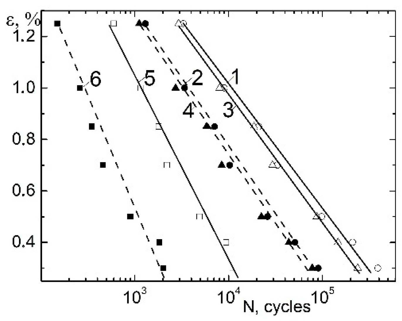
It was found that, in the studied range of amplitudes in the logarithmic coordinates of the load amplitude, the number of cycles to failure is represented by straight lines in both air and hydrogen, as described by the Coffin–Manson equations (Figure 17). It is known [57,58,59] that, under low-cycle loading, the magnitude of the deformation amplitude ε determines the time to crack formation, the stress-strain state at the crack tip and, when tested in the presence of hydrogen, the amount and nature of the distribution in the sample.
In steels with a high viscosity and a low yield strength, the level of local micro stresses for crack germination requires a high concentration of hydrogen [119,120,121,122,123,124,125], which decreases with the increasing frequency and amplitude of the load, which probably causes the weakening of the hydrogen embrittlement steels 25H2NMFA and 20H3NMFA (Figure 18, curves 1, 2).
The opposite pattern was found in tests of 17G1SU steel [54]—for large amplitudes of cyclic tensile, the effect of the corrosive environment on the number of cycles to the destruction of the parent metal and the weld is greater.
20H3NMFA steel with a higher strength and lower ductility has a lower durability and is stronger in hydrogen than 25H2NMFA steel. In the whole range of amplitudes, the influence of hydrogen on welded joints is very strong (Figure 18) and is illustrated by βN—the coefficient of hydrogen influence on the number of cycles to failure of samples made of 25H2NMFA and 20H3NMFA steels and their welded joint during low-cycle bending (βN = NH/NHe).
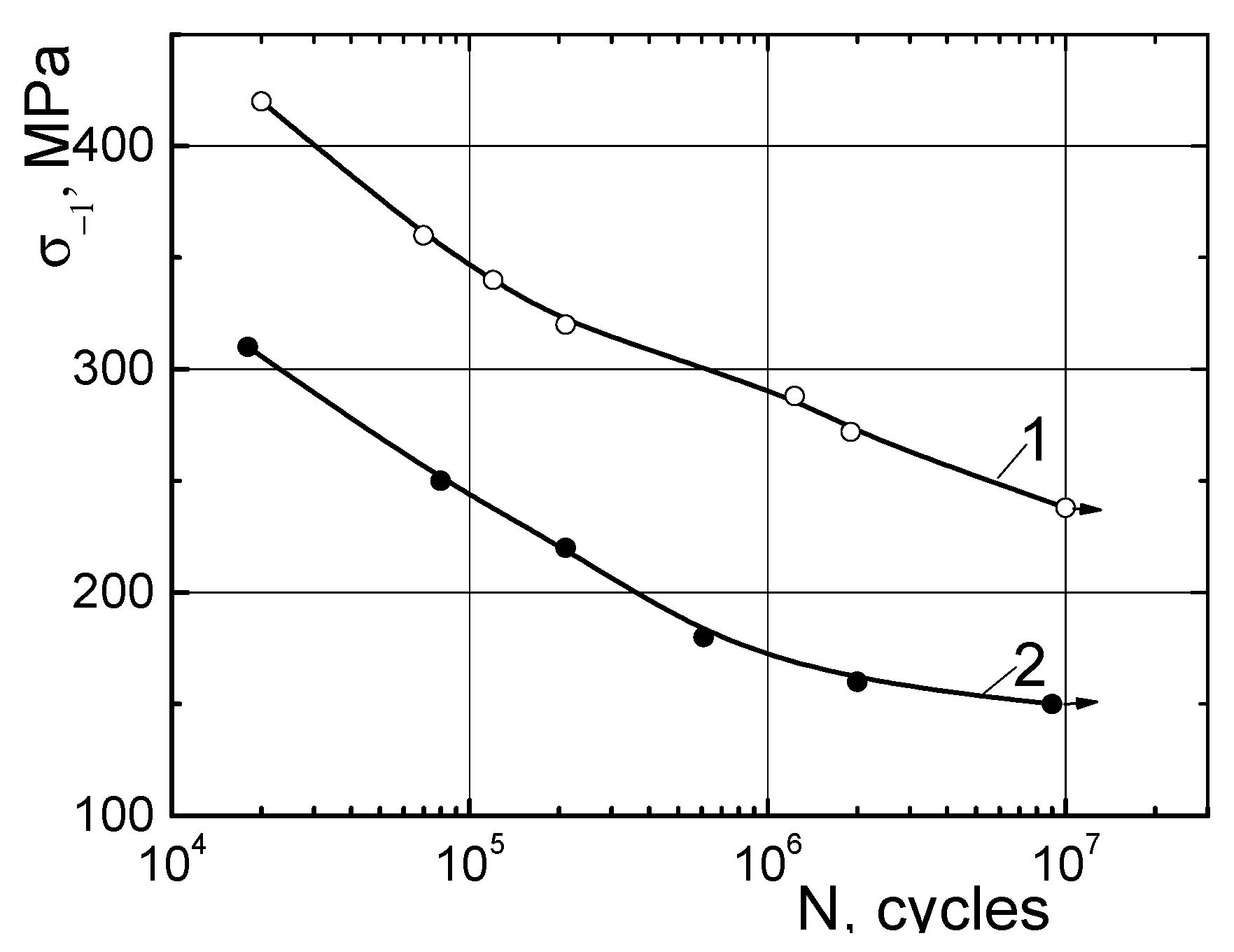
The endurance limit of cylindrical smooth specimens that rotate was determined by their bending. Cylindrical specimens for fatigue tests were cut from transverse templates of butt-welded joints. In the whole range of load amplitudes, the number of cycles before the destruction of combined welded joints is very sensitive to the action of hydrogen (Figure 19) and is significantly less than that of the rotor steel 38KhN3MFA [5].
An analysis of the improvement of up to 10–15% of the mechanical characteristics, hydrogen crack resistance and durability of rotor steels welded joint is possible in order to obtain an initial structure by the overheating and normalization of the HAZ and the formation of austenite grains reduced in size. This revealed that the specified welding heating creates conditions for the formation of new products of austenite decomposition in the form of sorbitol in the area of incomplete recrystallization.

7. Conclusions

It was established that the calculated values of temperatures obtained by simulating welding heating and the subsequent implementation of the welding process at the given mode parameters made it possible to obtain a welded joint of the rotor with an improved initial structure and increased the mechanical properties, hydrogen resistance and durability by 10–15%.
By simulating welding heating in the areas of the fusion, overheating and normalization of the HAZ, the formation of austenite grains reduced in size was provided.
It was revealed that the specified welding heating creates conditions for the formation of new products of austenite decomposition in the form of sorbitol in the area of the incomplete recrystallization of the HAZ.
It was shown that, in air and hydrogen, the destruction of the combined joints took place on the weld metal, as well as on the fusion areas, the overheating and the incomplete recrystallization of the HAZ of 20H3NMFA steel as the base metal. Structural materials have a relatively low strength and high viscosity of fracture in air.
At short-term stretching at room temperature, its effect is manifested in a significant reduction in the relative elongation δ, the relative transverse narrowing ψ and the critical stress intensity factor (KIc) of steels and, especially, welded joints. The fracture toughness, which is characteristic of many welds, deteriorates significantly (by 40–50%).
The endurance limit of cylindrical smooth specimens of rotor steel which were cut from transverse templates of butt-welded joints in the whole range of load amplitudes and the number of cycles before the destruction of combined welded joints are very sensitive to the action of hydrogen.

Author Contributions

The scope of the work of the individual authors during the performance of this project was the same. The authors performed the study together and then analyzed its findings. The paper was written together. The authors equally contributed to the paper assembly. Partially: conceptualization, A.I.B., V.V.D. and K.F.A.; data curation, O.A.B., V.V.D., M.A.K., J.J.E., G.P.S., L.B.M. and L.M.I.; formal analysis, J.J.E., L.M.I., A.V.G., V.V.D. and L.M.I.; investigation, L.M.I., A.V.G., G.P.S., L.B.M., V.V.D., J.J.E. and K.F.A.; methodology, A.I.B., O.A.B., M.A.K., K.F.A. and J.J.E.; writing—original draft, A.I.B.; writing—review and editing, A.I.B. and K.F.A.; software, O.A.B., A.V.G. and M.A.K.; validation, A.I.B., O.A.B. and A.V.G.; resources, L.B.M.; A.I.B. and A.V.G.; visualization, M.A.K.; supervision, A.I.B.; project administration, O.A.B.; funding acquisition, A.I.B. All authors have read and agreed to the published version of the manuscript.

Funding

This research received no external funding.

Institutional Review Board Statement

Not applicable.

Informed Consent Statement

Not applicable.

Data Availability Statement

Not applicable.

Acknowledgments

A.B. acknowledges the NCBR (Poland) for their partial support in the framework of project POIR.04.01.04-00-0040/20 “Development of an intelligent and maintenance-free system for stabilizing the operation of electricity distribution networks based on modular installations of a hydrogen energy buffer with the intention of utilizing hydrogen”.

Conflicts of Interest

The authors declare no conflict of interest.

Nomenclature and Abbreviations

σBultimate tensile strength (UTS)
σ0.2yield strength (YS)
σ−1fatigue limit
Nnumber of cycles
δelongation
ψreduction of area
εstrain
CHhydrogen concentration
wppmweight parts per millions
SIFstress-intensity factor
GTEgas turbine engine
GETenvironmentally ‘greener’ hydrogen energetic turbine
HCFhigh-cycle fatigue
LCFlow-cycle fatigue
RPMrotation per minute
HCEhydrogen-containing environment
HEhydrogen embrittlement phenomena
UEPSUnited Electric Power System
PSES.A.Polish Power System
FPPfossil power plant
NPPnuclear power plant
TAturboaggregate (turbine + turbogenerator)
TGturbogenerator
HPhigh-pressure turbine
IPintermediate-pressure turbine
LPlow-pressure turbine
HAZheat-affected zone
WJwelded joint
WMweld metal
BMbase metal

References

  1. National Commission for State Regulation of Energy and Utilities (NCRECP) National Energy and Utilities Regulatory Commission. The Report on Conformity Assessment (Sufficiency) of Generating Capacities—2019 Has Been Approved; National Commission for State Regulation of Energy and Utilities (NCRECP) National Energy and Utilities Regulatory Commission: Kyiv, Ukraine, 2020. Available online: http://www.nerc.gov.ua/?news=10017 (accessed on 20 July 2022).
  2. McCloskey, T.H.; Dooley, R.B.; McNaughton, W.P. Turbine Steam Path Damage: Theory and Practice; V. 1: Turbine Fundamentals; EPRI Cornice Engineering Inc.: Pleasant Hill, CA, USA, 1999; 614p, Available online: https://www.epri.com/research/products/TR-108943-V1 (accessed on 20 July 2022).
  3. McCloskey, T.H.; Dooley, R.B.; McNaughton, W.P. Turbine Steam Path Damage: Theory and Practice; V. 2: Damage Mechanisms; EPRI Cornice Engineering Inc.: Pleasant Hill, CA, USA, 1999; 676p, Available online: https://www.epri.com/research/products/TR-108943-V2 (accessed on 20 July 2022).
  4. Bancalari, E.; Chan, P.; Diakunchak, I.S. Advanced Hydrogen Turbine Development. In Proceedings of the ASME Turbo Expo 2007: Power for Land, Sea, and Air, Montreal, QC, Canada, 14–17 May 2007; pp. 977–987, Paper No: GT2007-27869. [Google Scholar] [CrossRef]
  5. Balitskii, A.I.; Ivaskevich, L.M.; Balitskii, O.A. Rotor steels crack resistance and fracture behavior for hydrogen targeted materials ever-widening database. Eng. Fract. Mech. 2022, 260, 108168. [Google Scholar] [CrossRef]
  6. Balitskii, A.I.; Makhnenko, O.V.; Balitskii, O.A.; Grabovskii, V.A.; Zaverbnyi, D.M.; Timofeev, B.T. Strength of materials and durability of structural elements of nuclear power plants. In Fracture Mechanics and Strength of Materials: Reference Book; Panasyuk, V.V., Ed.; Akademperiodyka: Kyiv, Ukraine, 2005; Volume 8, 544p, ISBN 966-360-035-7. Available online: http://catalog.loc.gov (accessed on 20 July 2022).
  7. Balitskii, A.I.; Boichenko, Y.A.; Sosnin, A.V.; Shokov, N.A. Cyclic crack resistance of rotor steel as a function of loading conditions. Met. Sci. Heat Treat. 1987, 29, 266–269. [Google Scholar] [CrossRef]
  8. Balitskii, A.; Krohmalny, O.; Ripey, I. Hydrogen cooling of turbogenerators and the problem of rotor retaining ring materials degradation. Int. J. Hydrogen Energy 2000, 25, 167–171. [Google Scholar] [CrossRef]
  9. Balyts’kyi, O.I.; Krokhmal’nyi, O.O. Pitting corrosion of 12Kh18AG18Sh steel in chloride solutions. Mater. Sci. 1999, 35, 389–394. [Google Scholar] [CrossRef]
  10. Tsaruk, A.K.; Muravetskii, S.I.; Skulskii, V.Y.; Grishin, N.N.; Vavilov, A.V.; Kantor, A.G. A forge-welded combined medium pressure rotor for 325 MW steam turbine. Paton Weld. J. 2012, 8, 39–44. Available online: https://patonpublishinghouse.com/as/pdf/2012/pdfarticles/08/8.pdf (accessed on 20 July 2022).
  11. Bojko, A.V.; Govoruschenko, Y.N.; Usatyj, A.P.; Rudenko, A.S. Optimization of flowing parts of gas turbines taking into account modes of operation within the limits of system of automated designing turbine unit. East.-Eur. J. Enterp. Technol. 2018, 45, 74–77. [Google Scholar] [CrossRef]
  12. Borisov, I.A. Effect of overheating on the texture and grain size of rotor steel. Met. Sci. Heat Treat. 2010, 52, 294–299. [Google Scholar] [CrossRef]
  13. Borisov, I.A.; Dub, A.V. Effect of duration of high-temperature tempering on the texture and grains of superheated rotor steel. Met. Sci. Heat Treat. 2013, 55, 117–123. [Google Scholar] [CrossRef]
  14. German, S.I.; Levenberg, N.E.; Netesa, E.M.; Fomina, O.P. Structure of the heat-affected zone in weldments of steel 24Kh2NMFA. Met. Sci. Heat Treat. 1977, 19, 1051–1054. [Google Scholar] [CrossRef]
  15. Balyts’kyi, O.I. The International Conference “Welded Structures”. Mater. Sci. 2000, 36, 941–942. [Google Scholar] [CrossRef]
  16. Smetankina, H.V. An oncanonically-shape laminated plate subjected to inpact loading. Trans. ASME J. Appl. Mech. 2008, 5, 051004. [Google Scholar] [CrossRef]
  17. Bolobov, V.I.; Latipov, I.U.; Popov, G.G.; Buslaev, G.V.; Martynenko, Y.V. Estimation of the influence of compressed hydrogen on the mechanical properties of pipeline steels. Energies 2021, 14, 6085. [Google Scholar] [CrossRef]
  18. Kawiak, M.; Balitskii, A. Embrittlement of welded joints of tram rails in city environments. Eng. Fail. Anal. 2018, 85, 97–103. [Google Scholar] [CrossRef]
  19. Balyts’kyi, O.I.; Kostyuk, I.F. Strength of welded joints of Cr-Mn steels with elevated content of nitrogen in hydrogen-containing media. Mater. Sci. 2009, 45, 97–107. [Google Scholar] [CrossRef]
  20. Magdowski, R.M.; Speidel, M.O. Clean steels for steam turbine rotors—Their stress corrosion cracking resistance. Metall. Trans. A 1988, 19, 1583–1596. [Google Scholar] [CrossRef]
  21. Viswanathan, R.; Bakker, W. Materials for ultrasupercritical coal power plants—Turbine materials: Part 2. J. Mater. Eng. Perform. 2001, 10, 96–101. [Google Scholar] [CrossRef]
  22. Foulds, J.; Viswanathan, R. Small punch testing for determining the material toughness of low alloy steel components in ervice. J. Eng. Mater. Technol. 1994, 116, 457–464. [Google Scholar] [CrossRef]
  23. Jaske, C.E.; Viswanathan, R. Use of miniature specimens for creep–crack–growth testing. J. Eng. Mater. Technol. 2000, 122, 327–332. [Google Scholar] [CrossRef]
  24. Balytskyi, O.I.; Mascalzi, G. Materials selection for high–speed motor rotor. Mater. Sci. 2002, 38, 293–303. [Google Scholar] [CrossRef]
  25. Eckardt, D.; Rufli, P. Advanced gas turbine technology: ABB/BCC historical first. Trans. ASME 2002, 124, 542–549. [Google Scholar] [CrossRef]
  26. Krasovskii, A.Y.; Vainshtok, V.A. Use of fracture mechanics to evaluate the bearing capacity and remaining life of rotors in turbomachinery. Strength Mater. 1982, 14, 997–1005. [Google Scholar] [CrossRef]
  27. Viswanathan, R.; Stringer, J. Failure mechanisms of high temperature components in power plants. J. Eng. Mater. Technol. 2000, 122, 246–255. [Google Scholar] [CrossRef]
  28. Olmi, G.; Freddi, A. Low cycle fatigue behavior and anisotropy of two steels for turbogenerator coil retaining ring and rotors. In Proceedings of the 9th Youth Symposium on Experimental Solid Mechanics, Trieste, Italy, 7–10 July 2010; pp. 188–192, ISBN 978-88-95940-30-4. Available online: https://www.semanticscholar.org/paper/Low-cycle-fatigue-behaviour-and-anisotropy-of-two-Olmi-Freddi/6a7b4c86f579967fa26aa7062db32c01119a2743 (accessed on 20 July 2022).
  29. Olmi, G. An efficient method for the determination of the probability of failure on the basis of LCF data: Application to turbogenerator design. Struct. Durab. Health Monit. 2012, 8, 61–89. [Google Scholar]
  30. Balyts’kyi, O.I.; Ripei, I.V.; Protsakh, K.A. Degradation of the cast elements of steam turbines of thermal power plants made of 20KhMFL steel in the course of long-term operation. Mater. Sci. 2005, 41, 423–426. [Google Scholar] [CrossRef]
  31. Balyts’kyi, O.I.; Ripey, I.V.; Protsakh, K.A. Reliability of steam pipelines of thermal power plants in the course of long-term operation. Mater. Sci. 2006, 42, 421–424. [Google Scholar] [CrossRef]
  32. Balyts’kyi, O.I.; Ripey, I.V.; Onyshak, J.D. Variations of impact toughness of 12Kh1MF steel in operating steam pipelines of thermal power plants. Mater. Sci. 2009, 45, 826–830. [Google Scholar] [CrossRef]
  33. Ma, H.; Sun, L.; Luo, H.; Li, X. Hydrogen embrittlement of high-strength marine steel as a weld joint in artificial seawater under cathodic polarization. Eng. Fail. Anal. 2022, 134, 106044. [Google Scholar] [CrossRef]
  34. Balitskii, A.I.; Medovar, L.B. Some problems of the production of materials for power engineering. In Advances in Electrometallurgy; Cambridge International Scientific Publication: Cambridge, UK, 2011; Volume 9, pp. 7–11. ISSN 1810-0384. Available online: http://pwi-scientists.com/pdf/journals/aiem201101.pdf (accessed on 20 July 2022). [CrossRef]
  35. Balitsky, A.I.; Kostyuk, I.F.; Krokhmalny, O.A. Physical-mechanical non-homogeneity of welded joints of high-nitrogen Cr-Mn steels and their corrosion resistance. Paton Weld. J. 2003, 2, 26–29. [Google Scholar]
  36. National Aeronautics and Space Administration; US Department of Commerce; National Institute of Standards and Technology. Plane Strain Crack Toughness Testing of High Strength Metallic Materials. ASTM Special Technical Publication No 410. 1996. Available online: https://www.amazon.com/toughness-strength-materials-technical-publication/dp/B0006BOYJQ (accessed on 20 July 2022).
  37. BS 6980; Corrosion of Metals and Alloys—Stress Corrosion Testing. Part 6: Method for the Preparation and Use of Pre-Cracked. BSI: London, UK, 1990; 32p. Available online: https://www.corrosionclinic.com/corrosion_resources/british_corrosion_standards.htm (accessed on 20 July 2022).
  38. ISO/DIS 7539-7; Corrosion of Metals and Alloys—Stress Corrosion Testing. Part 7: Slow Strain Rate Stress Corrosion Tests. International Organization for Standardization: Geneva, Switzerland, 1988; 6p. Available online: https://webstore.ansi.org/Standards/DIN/dineniso75392018?gclid=CjwKCAjwq5-WBhB7EiwAl-HEkugoPIGCTnUOzB1cJC32NcM_OFfyBxarw9GClSX_y1capBOw3eCXsBoC69EQAvD_BwE (accessed on 20 July 2022).
  39. Recommendation for Stress Corrosion Testing Using Pre-Cracked Specimens. ESIS Procedures 1992, 4-92 D. Available online: https://www.structuralintegrity.eu/site/events/esis-procedures (accessed on 20 July 2022).
  40. ASTM Special Technical Publication No E 561; National Aeronautics and Space administration; US Department of Commerce; National Institute of Standards and Technology. Middle-Cracked Tension Panel Test Setup. 2022. Available online: https://webstore.ansi.org/sdo/astm?gclid=CjwKCAjwq5-WBhB7EiwAl-HEknLYmGapAbqS13gK1Qv6Zo4iENkSzzoNt3gen_DPH0BP2lj9kZxF_BoC4OEQAvD_BwE (accessed on 20 July 2022).
  41. Vaßen, R.; Emine Bakan, E.; Mack, D.E.; Guillon, O. A Perspective on thermally sprayed thermal barrier coatings: Current status and trends. Journal of Thermal Spray Technology 2022 31, 685–698. [CrossRef]
  42. Wang, X.; Wang, D.; Deng, C.; Li, C. Effect of H2S corrosion on the fracture toughness of the X80 pipeline steel welded joint. Materials 2022, 15, 4458. [Google Scholar] [CrossRef]
  43. Ivas’kevych, L.M.; Tkachov, V.I. Mechanical properties of welded joints of heat-resistant KhN55MBYu alloy in hydrogen. Mater. Sci. 2000, 36, 925–927. [Google Scholar] [CrossRef]
  44. Tkachov, V.I.; Ivas’kevych, L.M.; Voznychak, O.M. Effect of hydrogen on the mechanical properties of welded joints of 03Kh12N10MT Steel and KhN55MBYu Alloy. Mater. Sci. 2004, 40, 772–780. [Google Scholar] [CrossRef]
  45. Khoma, M.S.; Chuchman, M.R.; Ivashkiv, V.R.; Sysyn, H.M. Influence of cyclic loads on the fracture resistance of pipe steels and their welded joints in hydrogen-sulfide media. Mater. Sci. 2013, 49, 334–340. [Google Scholar] [CrossRef]
  46. Dmytrakh, I.M.; Leshchak, R.L.; Syrotyuk, A.M.; Lutyts’kyi, O.L. Influence of the bulk concentration of hydrogen in the metal on the specific features of deformation of low-alloy pipe steel. Mater. Sci. 2014, 50, 170–178. [Google Scholar] [CrossRef]
  47. Balyts’kyi, O.I.; Ivas’kevych, L.M.; Eliasz, J.J. Static crack resistance of heat-resistant KhN43MBTYu nickel-chromium alloy in gaseous hydrogen. Strength Mater. 2020, 52, 386–397. [Google Scholar] [CrossRef]
  48. Balitskii, A.; Ivaskevich, L. Hydrogen effect on cumulation of failure, mechanical properties, and fracture toughness of Ni-Cr alloys. Adv. Mater. Sci. Eng. 2019, 3680253, 8. [Google Scholar] [CrossRef]
  49. Markashova, L.; Berdnikova, O.; Bernatskyi, A.; Sydorets, V.; Bushma, O. Crack resistance of 14KhGN2MDAFB high-strength steel joints manufactured by laser welding. IOP Conf. Ser. Earth Environ. Sci. 2019, 224, 012013. [Google Scholar] [CrossRef]
  50. Wang, W.; Guo, Y.; Li, Y.; Li, Z. Fracture toughness of different region materials from a dissimilar metal welded joint in steam turbine rotor. Coatings 2022, 12, 174. [Google Scholar] [CrossRef]
  51. Berdnikova, O.; Pozniakov, V.; Bernatskyi, A.; Alekseienko, T.; Sydorets, V. Effect of the structure on the mechanical properties and cracking resistance of welded joints of low-alloyed high-strength steels. Procedia Struct. Integr. 2019, 16, 89–96. [Google Scholar] [CrossRef]
  52. Panasyuk, V.V.; Dmytrakh, I.M.; Toth, L.; Bilyi, O.L.; Syrotyuk, A.M. A method for the assessment of the serviceability and fracture hazard for structural elements with cracklike defects. Mater. Sci. 2014, 49, 565–576. [Google Scholar] [CrossRef]
  53. Balitskii, A.I.; Diener, M.; Magdowski, R.M.; Pokhmurskii, V.I.; Speidel., M.O. Anisotropy of fracture toughness of austenitic high nitrogen chromium—Manganese steel. In Materials Science Forum; Trans Tech Publications Ltd.: Freienbach, Switzerland, 1999; Volume 318–320, pp. 401–406. [Google Scholar] [CrossRef]
  54. Benghalia, M.A.; Faces, C.; Khadrauui, A.; Meliani, M.H.; Obot, I.B.; Sorrour, A.; Dmytrakh, M.; Azari, Z. Performance evaluation of a natural and synthetic compound as corrosion inhibitors of API 5l X52 steel in hydrochloric acid media. Moroc. J. Chem. 2018, 6, 51–61. [Google Scholar] [CrossRef]
  55. Akid, R.; Dmytrakh, I.M.; Gonzalez-Sanchez, J. Fatigue damage accumulation: The role of corrosion on the early stages of crack development. Corros. Eng. Sci. Technol. 2006, 41, 328–335. [Google Scholar] [CrossRef]
  56. Georgiev, M.N.; Nikiforchin, G.M.; Mezhova, N.Y.; Strok, L.P.; Kozak, L.Y. Mechanism of the effect of hydrogen on fatigue crack propagation in structural steels. Sov. Mater. Sci. 1988, 24, 244–246. [Google Scholar] [CrossRef]
  57. Aksimentyeva, O.I.; Demchenko, P.Y.; Savchyn, V.P.; Balitskii, O.A. The chemical exfoliation phenomena in layered GaSe-polyaniline composite. Nanoscale Res. Lett. 2013, 8, 29. [Google Scholar] [CrossRef] [PubMed]
  58. Tkachov, V.I.; Ivas’kevych, L.M.; Vytvyts’kyi, V.I. Methodological aspects of determination of hydrogen resistance of steels. Mater. Sci. 2002, 38, 484–493. [Google Scholar] [CrossRef]
  59. Balyts’kyi, O.I.; Ivas’kevych, L.M. Load rate-related mechanical properties of steels and alloys under static and cyclic loading in gaseous hydrogen. Strength Mater. 2021, 53, 430–439. [Google Scholar] [CrossRef]
  60. Li, H.L.; Gao, K.W.; Qiao, L.J.; Wang, Y.B.; Chu, W.Y. Strength effect in stress corrosion cracking of high-strength steel in aqueous solution. Corrosion 2001, 57, 295–299. [Google Scholar] [CrossRef]
  61. Zhang, T.; Chu, W.Y.; Gao, K.W.; Qiao, L.J. Study of correlation between hydrogen-induced stress and hydrogen embrittlement. Mater. Sci. Eng. A 2003, 347, 291–299. [Google Scholar] [CrossRef]
  62. Jun, H.K.; Seo, J.W.; Jeon, I.S.; Lee, S.H.; Chang, Y.S. Fracture and fatigue crack growth analyses on a weld-repaired railway rail. Eng. Fail. Anal. 2016, 59, 478–492. [Google Scholar] [CrossRef]
  63. Weijun, H.; Zhibao, X.; Yongjian, Z.; Xiaoli, Z.; Chengwei, S.; Yuqing, W. Hydrogen embrittlement behavior of high strength rail steels: A comparison between pearlitic and bainitic microstructure. Mater. Sci. Eng. A 2017, 704, 199–206. [Google Scholar]
  64. Wasim, M.; Djukic, M.; Ngo, T.D. Influence of hydrogen-enhanced plasticity and decohesion mechanisms of hydrogen embrittlement on the fracture resistance of steel. Eng. Fail. Anal. 2021, 123, 105312. [Google Scholar] [CrossRef]
  65. Djukic, M.; Curtin, W.A.; Zhang, Z.; Sedmak, A. Recent advances on hydrogen embrittlement understanding and future research framework. Eng. Fract. Mech. 2021, 241, 107439. [Google Scholar] [CrossRef]
  66. Wasim, M.; Djukic, M. Hydrogen embrittlement of low carbon structural steel at macro-, micro- and nano-levels. Int. J. Hydrogen Energy 2020, 45, 2145–2156. [Google Scholar] [CrossRef]
  67. Rozumek, D.; Macha, E. Elastic-plastic fatigue crack growth in 18G2A steel under proportional bending with torsion loading. Fatigue Fract. Eng. Mater. Struct. 2006, 29, 135–145. [Google Scholar] [CrossRef]
  68. Djukic, M.B.; Bakic, G.M.; Sijacki Zeravcic, V.; Sedmak, A.; Rajicic, B. The synergistic action and interplay of hydrogen embrittlement mechanisms in steels and iron: Localized plasticity and decohesion. Eng. Fract. Mech. 2019, 216, 106528. [Google Scholar] [CrossRef]
  69. Michler, T.; Naumann, J.; Wiebesiek, J.; Sattler, E. Influence of frequency and wave form on S-N fatigue of commercial austenitic stainless steels with different nickel contents in inert gas and in high pressure gaseous hydrogen. Int. J. Fatigue 2017, 96, 67–77. [Google Scholar] [CrossRef]
  70. Michler, T.; Naumann, J.; Sattler, E. Influence of high pressure gaseous hydrogen on S-N fatigue in two austenitic stainless steels. Int. J. Fatigue 2013, 51, 1–7. [Google Scholar] [CrossRef]
  71. Khoma, M.S.; Vasyliv, K.B.; Chuchman, M.R. Influence of the hydrogen sulfide concentration on the corrosion and hydrogenation of pipe steels (A Survey). Mater Sci 2021, 57, 308–318. [Google Scholar] [CrossRef]
  72. Rozumek, D.; Marciniak, Z. Fatigue properties of notched specimens made of FeP04 Steel. Mater. Sci. 2012, 47, 462–469. [Google Scholar] [CrossRef]
  73. Moustabchir, H.; Azari, Z.; Hairi, S.; Dmytrakh, I. Experimental and computed stress distribution ahead of notch in pressure vessel: Application of T-stress conception. Comput. Mater. Sci. 2012, 58, 59–66. [Google Scholar] [CrossRef]
  74. Balitskii, A.I.; Ivaskevich, L.M. Assessment of hydrogen embrittlement in high-alloy chromium-nickel steels and alloys in hydrogen at high pressures and temperatures. Strength Mater. 2018, 50, 880–887. [Google Scholar] [CrossRef]
  75. Karpenko, G.V.; Litvin, A.K.; Tkachev, V.I.; Soshko, A.I. Mechanism of hydrogen embrittlement. Sov. Mater. Sci. 1975, 9, 367–371. [Google Scholar] [CrossRef]
  76. Qu, J.; Feng, M.; An, T.; Bi, Z.; Du, J.; Yang, F.; Zheng, S. Hydrogen-assisted crack growth in the heat-affected zone of X80 steels during in situ hydrogen charging. Materials 2019, 12, 2575. [Google Scholar] [CrossRef]
  77. Kozak, L.Y. Discrete models of plastic deformation of solids under the action of high hydrostatic pressure. Mater. Sci. 2016, 52, 108–112. [Google Scholar] [CrossRef]
  78. Chu, S.; Zhang, C.; Yang, Z.; Wang, C. Hydrogen’s influence on reduced activation ferritic/martensitic steels’ elastic properties: Density functional theory combined with experiment. Nuclear Eng. Technol. 2017, 49, 1748–1751. [Google Scholar] [CrossRef]
  79. Romaniv, O.N.; Nikiforchin, G.N.; Kozak, L.Y. Structural sensitivity of the cyclic crack resistance of rotor steel in gaseous hydrogen. Sov. Mater. Sci. 1984, 20, 424–429. [Google Scholar] [CrossRef]
  80. Romaniv, O.N.; Nikiforchin, G.N.; Kozak, L.Y. Cyclic rack resistance of constructional steel in gaseous hydrogen. Sov. Mater. Sci. 1987, 23, 439–450. [Google Scholar] [CrossRef]
  81. Balitskii, O.A.; Savchyn, V.P.; Savchyn, P.V. Thermal oxidation of indium and gallium sulphides. Phys. B Condens. Matter 2005, 355, 365–369. [Google Scholar] [CrossRef]
  82. Syrotyuk, A.M.; Dmytrakh, I.M. Methods for the evaluation of fracture and strength of pipeline steels and structures under the action of working media. Part II: Influence of hydrogen-containing media. Mater. Sci. 2015, 50, 475–487. [Google Scholar] [CrossRef]
  83. Dmytrakh, I.M.; Leshchak, R.L.; Syrotyuk, A.M.; Barna, R.A. Effect of hydrogen concentration on fatigue crack growth behaviour in pipeline steel. Int. J. Hydrogen Energy 2017, 42, 6401–6408. [Google Scholar] [CrossRef]
  84. Zima, Y.V.; Kozak, L.Y. Fractographic aspects of the cyclic crack resistance of 35KhN3MFA steel in vacuum, air, and hydrogen. Mater. Sci. 1986, 22, 268–275. [Google Scholar] [CrossRef]
  85. Sandia National Laboratories. Technical Database for Hydrogen Compatibility of Materials; Sandia National Laboratories: Livermore, CA, USA, 2022; Available online: https://h2tools.org/technical-database-hydrogencompatibility-materials (accessed on 20 July 2022).
  86. Inés, M.N.; Asmus, C.A.; Mansilla, G.A. Influence of total strain amplitude on hydrogen embrittlement of high strength steel. Procedia Mater. Sci. 2013, 8, 1039–1046. [Google Scholar] [CrossRef]
  87. Mansilla, G.; Herenú, S.; Brandaleze, E. Hydrogen effects on low cycle fatigue of high strength steels. Mater. Sci. Technol. 2014, 30, 501–505. [Google Scholar] [CrossRef]
  88. Renshaw, C.E.; Schulson, E.M. Universal behavior in compressive failure of brittle materials. Nature 2001, 412, 897–926. [Google Scholar] [CrossRef] [PubMed]
  89. Balyts’kyi, O.O. Elastic characteristics of laminated gallium and indium chalcogenides. Mater. Sci. 2004, 40, 706–709. [Google Scholar] [CrossRef]
  90. Frankowska, M.; Błoński, K.; Mańkowska, M.; Rzeczycki, A. Research on the concept of hydrogen supply chains and power grids powered by renewable energy sources: A scoping review with the use of text mining. Energies 2022, 15, 866. [Google Scholar] [CrossRef]
  91. Frankowska, M.; Mańkowska, M.; Rabe, M.; Rzeczycki, A.; Szaruga, E. Structural model of power grid stabilization in the green hydrogen supply chain system—Conceptual assumptions. Energies 2022, 15, 664. [Google Scholar] [CrossRef]
  92. Drożdż, W.; Elżanowski, F.; Dowejko, J.; Brożyński, B. Hydrogen technology on the polish electromobility market. Legal, economic, and social aspects. Energies 2021, 14, 2357. [Google Scholar] [CrossRef]
  93. Wróblewski, P.; Drożdż, W.; Lewicki, W.; Dowejko, J. Total cost of ownership and its potential consequences for the development of the hydrogen fuel cell powered vehicle market in Poland. Energies 2021, 14, 2131. [Google Scholar] [CrossRef]
  94. Smolenski, R.; Lezynski, P.; Bojarski, J.; Drozdz, W.; Long, L.C. Electromagnetic compatibility assessment in multiconverter power systems—Conducted interference issues. Measurement 2020, 165, 108119. [Google Scholar] [CrossRef]
  95. Lezynski, P.; Szczesniak, P.; Waskowicz, B.; Smolenski, R.; Drozdz, W. Design and implementation of a fully controllable cyber-physical system for testing energy storage systems. IEEE Access 2019, 7, 47259–47272. [Google Scholar] [CrossRef]
  96. IIW Guidance on Assessment of the Fitness for Purpose of Welded Structures. IIW/118–SST–1157–90. 1990. Available online: https://www.worldcat.org/title/iiw-guidance-on-assessment-of-fitness-for-purpose-of-welded-structures-draft-for-development-iisiiw-sst-1157-90/oclc/438482115 (accessed on 20 July 2022).
  97. Wen, X.; Wang, P.; Dong, Z.; Fang, H. A Fracture mechanics-based optimal fatigue design method of under-matched HSLA steel butt-welded joints with imperfections. Appl. Sci. 2019, 9, 3609. [Google Scholar] [CrossRef]
  98. Leicher, J.; Schaffert, J.; Cigarida, H.; Tali, E.; Burmeister, F.; Giese, A.; Albus, R.; Görner, K.; Carpentier, S.; Milin, P.; et al. The impact of hydrogen admixture into natural gas on residential and commercial gas appliances. Energies 2022, 15, 777. [Google Scholar] [CrossRef]
  99. Horn, R.M.; Kass, J.N.; Rangantath, K. Evaluation of the growth and stability of stress corrosion cracking in sensitired austenitic pipings. J. Press. Vessel Technol. 1984, 106, 201–208. [Google Scholar] [CrossRef]
  100. Xing, Y.; Yang, Z.; Yao, X.; Wang, X.; Lu, M.; Zhang, L.; Qiao, L. Effects of hydrogen on the fracture toughness of X80 steel base metal and girth weld under strong cathodic current with in-situ hydrogen charging. Eng. Fail. Anal. 2022, 135, 106143. [Google Scholar] [CrossRef]
  101. Hoyos, J.J.; Masoumi, M.; Pereira, V.F.; Tschiptschin, A.P.; Paes, M.T.P.; Avila, J.A. Influence of hydrogen on the microstructure and fracture toughness of friction stir welded plates of API 5L X80 pipeline steel. Int. J. Hydrogen Energy 2019, 44, 23458–23471. [Google Scholar] [CrossRef]
  102. Bihun, R.I.; Stasyuk, Z.V.; Balitskii, O.A. Crossover from quantum to classical electron transport in ultrathin metal films. Phys. B Condens. Matter 2016, 487, 73–77. [Google Scholar] [CrossRef]
  103. Zhang, C.; Ran, M.; Wang, Y.; Zheng, W. Microstructural effects in the development of near-neutral pH stress corrosion cracks in pipelines. Materials 2022, 15, 4372. [Google Scholar] [CrossRef]
  104. Li, H.; Dong, F.; Zhou, Q.; Shi, Z.; Venezuela, J.; Yan, M.; Knibbe, R.; Zhang, M.; Atrens, A. Influence of hydrogen on the S–N fatigue of DP1180 advanced high-strength steel. Corros. Sci. 2022, 205, 110465. [Google Scholar] [CrossRef]
  105. Qazi, U.Y. Future of hydrogen as an alternative fuel for next-generation industrial applications; Challenges and expected opportunities. Energies 2022, 15, 4741. [Google Scholar] [CrossRef]
  106. Costa, J.V.; Silva, D.F.F.D.; Branco, P.J.C. Large-power transformers: Time now for addressing their monitoring and failure investigation techniques. Energies 2022, 15, 4697. [Google Scholar] [CrossRef]
  107. Pacheco, J.; Pimenta, F.; Pereira, S.; Cunha, Á.; Magalhães, F. Fatigue assessment of wind turbine towers: Review of processing strategies with illustrative case study. Energies 2022, 15, 4782. [Google Scholar] [CrossRef]
  108. Barisano, D.; Canneto, G.; Nanna, F.; Villone, A.; Fanelli, E.; Freda, C.; Grieco, M.; Lotierzo, A.; Cornacchia, G.; Braccio, G.; et al. Investigation of an intensified thermo-chemical experimental set-up for hydrogen production from biomass: Gasification process integrated to a portable purification system—Part II. Energies 2022, 15, 4580. [Google Scholar] [CrossRef]
  109. Galloni, E.; Lanni, D.; Fontana, G.; D’Antuono, G.; Stabile, S. Performance estimation of a downsized SI engine running with hydrogen. Energies 2022, 15, 4744. [Google Scholar] [CrossRef]
  110. Górecki, K.; Posobkiewicz, K. Cooling systems of power semiconductor devices—A Review. Energies 2022, 15, 4566. [Google Scholar] [CrossRef]
  111. Guo, X.; Xia, L.; Zhao, G.; Wei, G.; Wang, Y.; Yin, Y.; Guo, J.; Ren, X. Steam temperature characteristics in boiler water wall tubes based on furnace CFD and hydrodynamic coupling model. Energies 2022, 15, 4745. [Google Scholar] [CrossRef]
  112. Mukundakumar, N.; Bastiaans, R. DNS study of spherically expanding premixed turbulent ammonia-hydrogen flame kernels, Effect of equivalence ratio and hydrogen content. Energies 2022, 15, 4749. [Google Scholar] [CrossRef]
  113. Lu, L.; Zhu, M.; Wu, H.; Wu, J. A review and case analysis on biaxial synchronous loading technology and fast moment-matching methods for fatigue tests of wind turbine blades. Energies 2022, 15, 4881. [Google Scholar] [CrossRef]
  114. Wang, Y.; Wang, C.; Liu, G.; Zhang, C.; Li, J. An assessment method of sealing performance and stress intensity factors at crack tip of subsea connector metal sealing rings. Energies 2022, 15, 4680. [Google Scholar] [CrossRef]
  115. Jiao, A.; Tian, S.; Lin, H. Study on crack penetration induced by fatigue damage of low permeability coal seam under cyclic loading. Energies 2022, 15, 4761. [Google Scholar] [CrossRef]
  116. Feng, H.; Chen, L.; Tang, W.; Ge, Y. Optimal design of a dual-pressure steam turbine for rankine cycle based on constructal theory. Energies 2022, 15, 4854. [Google Scholar] [CrossRef]
  117. Allen, T.; Busby, J.; Meyer, M.; Petti, D. Materials challenges for nuclear systems. Mater. Today 2010, 13, 14–23. [Google Scholar] [CrossRef]
  118. Zafra, A.; Álvarez, G.; Benoit, G.; Hénaff, G.; Rodríguez, C.; Belzunce, J. Influence of hydrogen on the fatigue crack growth rate of 42CrMo4 steel welds: A comparison between pre-charge and in-situ testing. Procedia Struct. Integr. 2022, 39, 128–138. [Google Scholar] [CrossRef]
  119. Bailey, N.; Coe, F.R.; Gooch, T.G.; Hart, M.N.; Jenkins, P.H.; Pargeter, R.J. Welding Steels without Hydrogen Cracking; View Series: Woodhead Publishing Series in Welding and Other Joining Technologies; Elsevier: Amsterdam, The Netherlands, 1993; 150p, ISBN 9781855730144. eBook ISBN: 9780857093097. [Google Scholar]
  120. Karcı, F.; Kacar, R.; Gündüz, S. The effect of process parameter on the properties of spot welded cold deformed AISI304 grade austenitic stainless steel. J. Mater. Process. Technol. 2009, 209, 4011–4019. [Google Scholar] [CrossRef]
  121. BS EN 288-3:1992; Specification and Approval of Welding Procedures for Metallic Materials. Welding Procedure Tests for the Arc Welding of Steels. 1992; 30p. Available online: https://flot.com/law/standards/en288.pdf (accessed on 20 July 2022).
  122. Harzenmoser, M. Welding of high nitrogen steels. Mater. Manuf. Processes 2004, 19, 75–86. [Google Scholar] [CrossRef]
  123. Benoit, G.; Bertheau, D.; Hénaff, G.; Alvarez, L. Crack growth resistance of actual pipe weldments exposed to a high pressure mixture of hydrogen and natural gas. In Proceedings of the ASME Pressure Vessels and Piping Conference, Online, 13–15 July 2021; The American Society of Mechanical Engineers: Washington, DC, USA, 2021. [Google Scholar] [CrossRef]
  124. Barrera, O.; Bombac, D.; Chen, Y. Understanding and mitigating hydrogen embrittlement of steels: A review of experimental, modelling and design progress from atomistic to continuum. J. Mater. Sci. 2018, 53, 6251–6290. [Google Scholar] [CrossRef] [PubMed]
  125. Dadfarnia, M.; Nagao, A.; Wang, S.; Martin, M.L. Recent advances on hydrogen embrittlement of structural materials. Int. J. Fract. 2015, 196, 223–243. [Google Scholar] [CrossRef]
  126. Dmytrakh, I.M.; Syrotyuk, A.M.; Leschak, R.L. Fracture and Strength of Pipeline Steels in Hydrogen-Containing Environments; Publishing House “Prostir-M”: Lviv, Ukraine, 2020; 222p, ISBN 987-617-7746-67-5. [Google Scholar]
  127. Decelis, B.; Argon, A.S.; Yip, S. Molecular dynamics simulation of crack tip processes in alpha-iron and copper. J. Appl. Phys. 1983, 54, 4864. [Google Scholar] [CrossRef]
  128. Capelle, J.; Dmytrakh, I.; Gilgert, J.; Jodin, P.; Pluvinage, G. A comparison of experimental results and computations for ctacked tubes subjected to internal pressure. Mater. Technol. 2006, 40, 233–237. [Google Scholar]
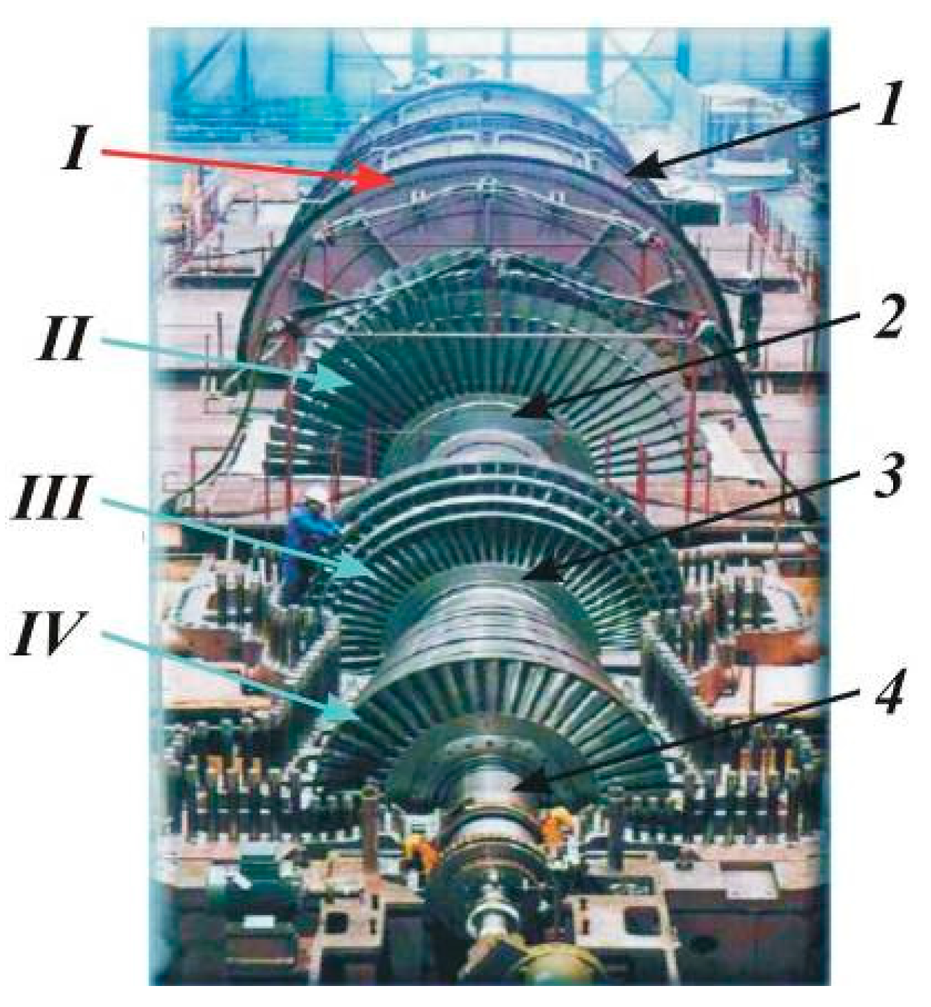
Figure 1. Hydrogen-cooled TA and possible rotor damage in the working environments: I—gaseous hydrogen (0.5 MPa MPa, 80 °C), II, III, IV—steam (0.25 … 5 MPa, 190 … 540 °C), rotors of TG (1), low (2), intermediate (3), high (4) steam turbine pressure [2,6].
Energies 15 06006 g001
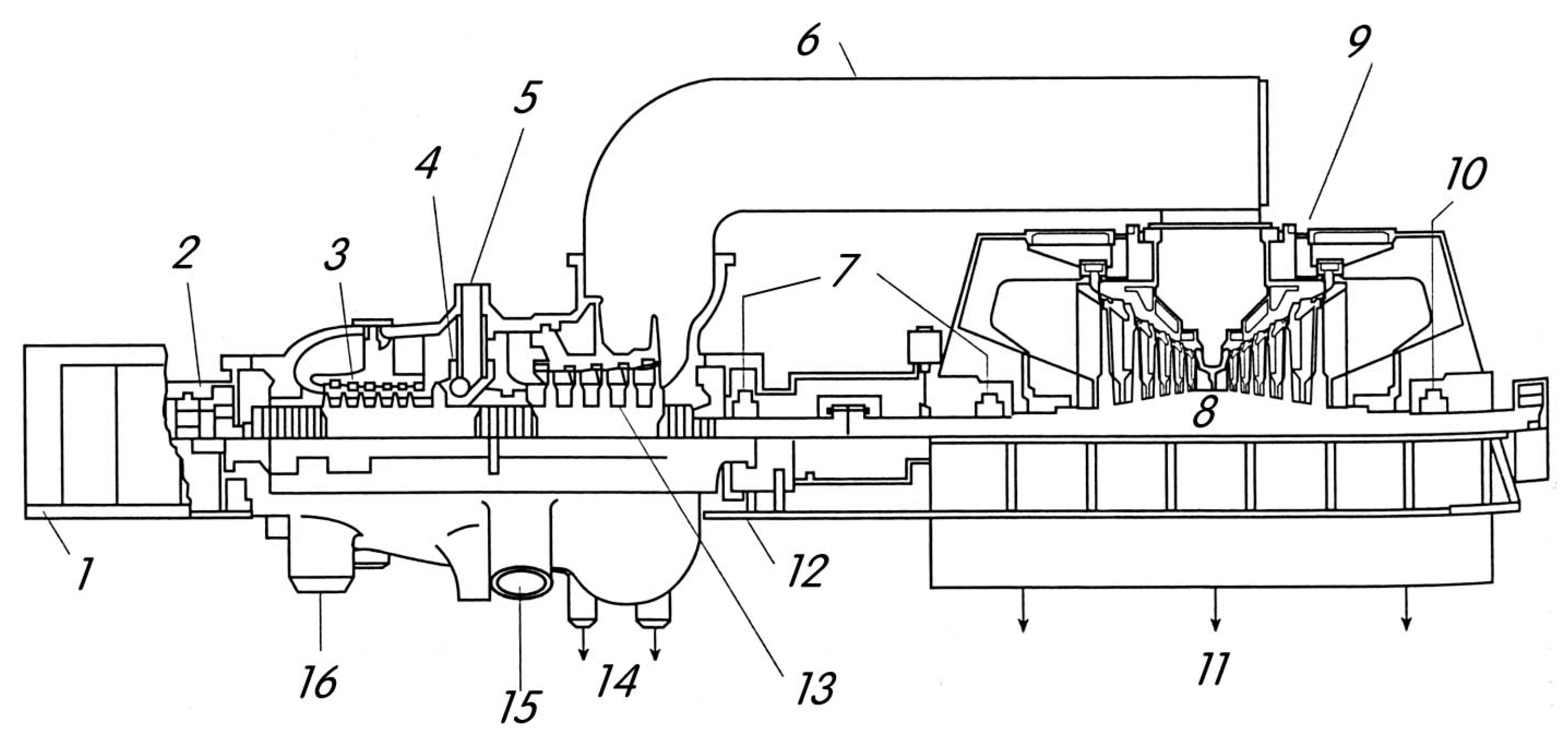
Figure 2. Typical tandem compound, single reheat, condensing turbine: 1—front pedestal; 2—thrust and journal bearing; 3—high pressure stages; 4—nozzle box; 5—HP turbine inlet; 6—crossover piping; 7—journal bearings; 8—rotor; 9—low pressure stages; 10—journal bearing; 11—to condenser; 12—pedestal; 13—intermediate pressure stages; 14—extractions; 15—IP turbine inlet; 16—to reheater [2].
Energies 15 06006 g002
Figure 3. Types of turbine rotor construction: (a)—schematic of a monoblock stream turbine rotor, (b1,b2)—schematic of a built-up stream turbine rotor with shrunk-on discs; (c)—schematic of a welded stream turbine rotor. The welds connect the discs (ABB Power Generation, Baden, Switzerland) [2,9,10,11,12,13,14,15,16,17,18,19,20,21,22,23]. Rotor body with detailed drawing of gaps for wedges and winding (d) [5]. Linear slots of the hydrogen cooled turbogenerator rotor shaft tail (original design). 1—rotor shaft; 2—current supply slot; 3—ventilation slot; 4—slot wedges; 5—current supply tire; 6—shaft fracture areas due to fretting (wedge joining areas) (e). Design slot wedges rotor tail after application of the antifretting measures system: 1—rotor shaft; 2—current supply slot; 3—ventilation slot; 4—current supply wedge; 5—current supply tire; 6—ventilation slot wedge; 7—easy shifting seal (f) [2,6,23,24,25,26,27,28,29,30,31,32,33,34].
Energies 15 06006 g003
Figure 4. The structure of the base metal of the welded joint from the steel 25H2NMFA. ×400. *—mkm.
Energies 15 06006 g004
Figure 5. Macrostructure of the welded joint of the prototype rotor.
Energies 15 06006 g005
Figure 6. Scheme of approximation of a fragment of a welded joint (see Figure 4). Ω1—base metal area; Ω2—area of the molten metal of the bath; Ω3—free surface of the bath melt.
Energies 15 06006 g006
Figure 7. Scheme of cutting templates from a welded joint for studying the structure, mechanical and crack resistance properties and determining the microhardness (1–3 template numbers).
Energies 15 06006 g007
Figure 8. Scheme of HAZ Sections: 1—fusion section, 2—overheating section, 3—normalization section, 4—incomplete recrystallization section, 5—weld metal, 6—base metal.
Energies 15 06006 g008
Figure 9. The structure of the weld metal of the welded joint made of the steel 25H2NMFA (Figure 7): (a)—template 1, (b)—template 2, (c)—template 3, (d)—original metal. ×400. *—mkm.
Energies 15 06006 g009
Figure 10. The fusion area (indicated by the arrow) of the HAZ of the welded joint, Template 3 (see Figure 11). ×400. *—mkm.
Energies 15 06006 g010
Figure 11. Structure of the overheating section, template 2 (Figure 7). ×400. *—mkm.
Energies 15 06006 g011
Figure 12. The structure of the area of incomplete recrystallization, template 2 (see Figure 7). ×400. *—mkm.
Energies 15 06006 g012
Figure 13. Distribution of microhardness over the cross section of template 2 (see Figure 7).
Energies 15 06006 g013
Figure 14. Scheme of cutting out samples that guarantees the spread of main fractures along the material of the welded joint (a,e), heat-affected zone (b,f) and core material (c,d); I, II, III—number of zones of a welded joint; s—distance from the axis of the seam to the notch [35,36,37,38,39,40].
Energies 15 06006 g014
Figure 15. Samples for studying the parameters of the static crack resistance of welded joints of different configurations. Guide (longitude) (a), perpendicular (b), T-shaped (c), cruciform (d) (for investigation of cross-like WJ, which simulates real structures’ shell-bottom vessels under hydrogen pressure), wedge loading schemes (d,e) of prismatic-type compact specimens (P-force, t, 2a + δ, b1—specimen thickness, width and length, d—hole diameter, h, l0, b—the distance from the hole center to the concentrator tip, the end of the initiated fatigue crack and the finish of the crack path) [36,37,38,39,40]: 1—guide plates, 2—wedge, 3—specimen, 4—guide plate (loaded with a wedge of two types of fixation) after specimens’ long-term exposure in gaseous hydrogen with high pressures and temperatures (f) [35,36,37,38,39,40].
Energies 15 06006 g015
Figure 16. Cracked specimens over the cross-section of the WJ template with a roof and different configurations (a,b), which, during crack propagation, can serve as traps for cracks and change their trajectory. Example of uncontrolled deviation of the crack propagation direction at the angle up to 90° (c).
Energies 15 06006 g016
Figure 17. Curves of low-cycle fatigue (number of cycles before failure—load amplitude) of samples of the steels 25H2NMFA (1,2) and 20H3NMFA (3,4) and their welded joint (5,6) in air (1,3,5) and hydrogen at a pressure of 10 MPa (2,4,6).
Energies 15 06006 g017
Figure 18. Dependencies of the coefficient of influence of hydrogen under a pressure of 10 MPa on the number of cycles to failure of samples made of 25H2NMFA (1) and 20H3NMFA (2) steels and their welded joint (3) on the amplitude of low-cycle bending.
Energies 15 06006 g018
Figure 19. Endurance curves of the combined compounds of the steel 20H3NMFA with the steel 25H2NMFA in air (1) and hydrogen at a pressure of 10 MPa (2).
Energies 15 06006 g019
Table 1. Chemical composition of the base metal, electrode wire and weld metal of the combined weld [2,3,4,5,10,34].
Investigated ObjectChemical Composition, Mas %
CSiMnCrNiMoVWSP
20H3NMFA0.20
(0.16–0.24)
0.30
(0.17–0.40)
0.34
(0.25–0.60)
3.0
(2.40–3.30)
0.20
(0.20–0.50)
0.65
(035–0.65)
0.70
(0.60–0.85)
0.46
(0.30–0.50)
≤0.012≤0.032
25H2NMFA0.240.340.461.02.550.460.02-≤0.014≤0.024
Wire
SV08HN2
GMYu
0.080.531.050.752.00.450.016-≤0.012≤0.018
Weld metal0.0560.250.980.731.80.450.003-≤0.012≤0.018
The content of Co (rotor of the primary circuit of the steam turbine) should not exceed 0.025%, Cu ≤ 0.25.
Table 2. The toughness of the weld metal of the combined welds after tempering at 630 °C for 30 h.
Investigated ObjectImpact Toughness KCV, J/cm2
20 °C−20 °C−40 °C
20H3NMFA105 … 78
91.5
60 … 45
55
40 … 30
35
25H2NMFA136 … 120
128
81 … 40
60.5
60 … 30
45
Weld metal
(wire SV08HN2GMYu)
100 … 72
86
50 … 35
42.5
39 … 31
35
Table 3. Impact toughness of samples with a V-notch along the HAZ (fusion and overheating areas) (Figure 4).
Investigated ObjectImpact Toughness KCV, J/cm2
Suggested Welding ProcessStandard Welding Process
Sample 1 (fusion area)7464
Sample 2 (fusion area)5957
Sample 3 (fusion area)6960
Sample 1 (overheating area)187176
Sample 2 (overheating area)171168
Sample 3 (overheating area)88178
Table 4. Mechanical properties of welded joints in air (upper value) and in hydrogen at a pressure of 10 MPa (down value).
Investigated ObjectT, °Cσ0.2, MPaσB, MPaδ, %ψ, %KIc, MPa∙m 1/2
Steel 20H3NMFA20620
610
730
710
11
8
32
21
112
61
450510
510
600
610
8
7
27
25
92
83
Steel 25H2NMFA20520
530
687
680
14
10
40
26
118
72
450460
430
570
580
12
12
40
36
101
91
Welded joint20530
510
690
690
24
11
67
31
39
21
450450
460
570
560
16
15
63
52
42
38
Publisher’s Note: MDPI stays neutral with regard to jurisdictional claims in published maps and institutional affiliations.