
Possibility of a Portable Power Generator Using Dielectric Elastomers and a Charging System for Secondary Batteries


Abstract
1. Introduction
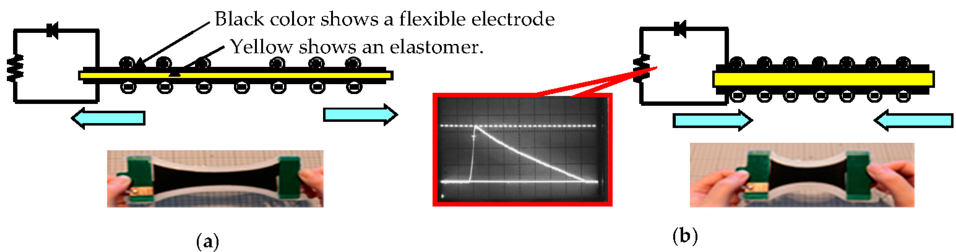
2. Background of the DEG System
3. Experimental Procedure
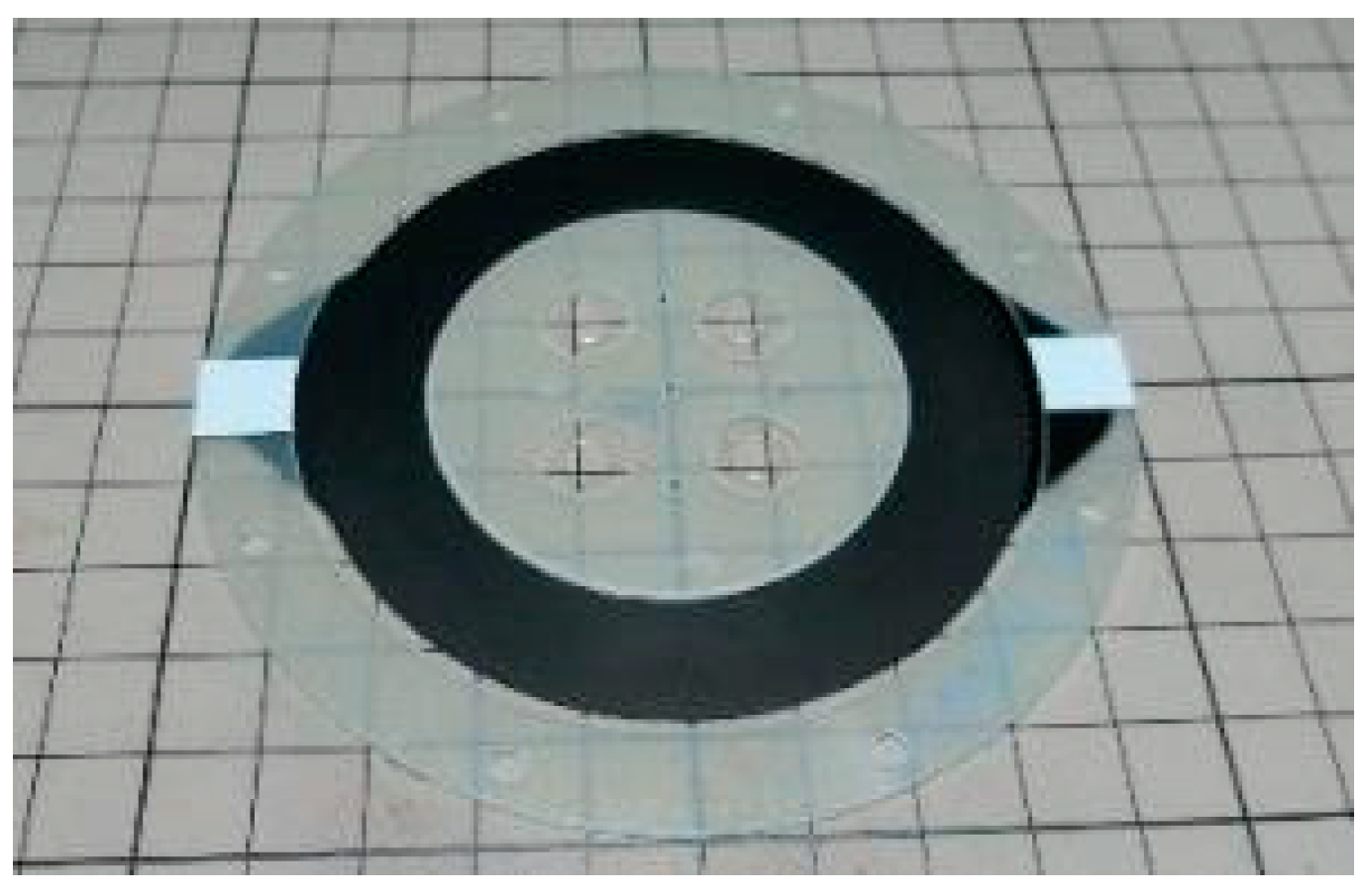
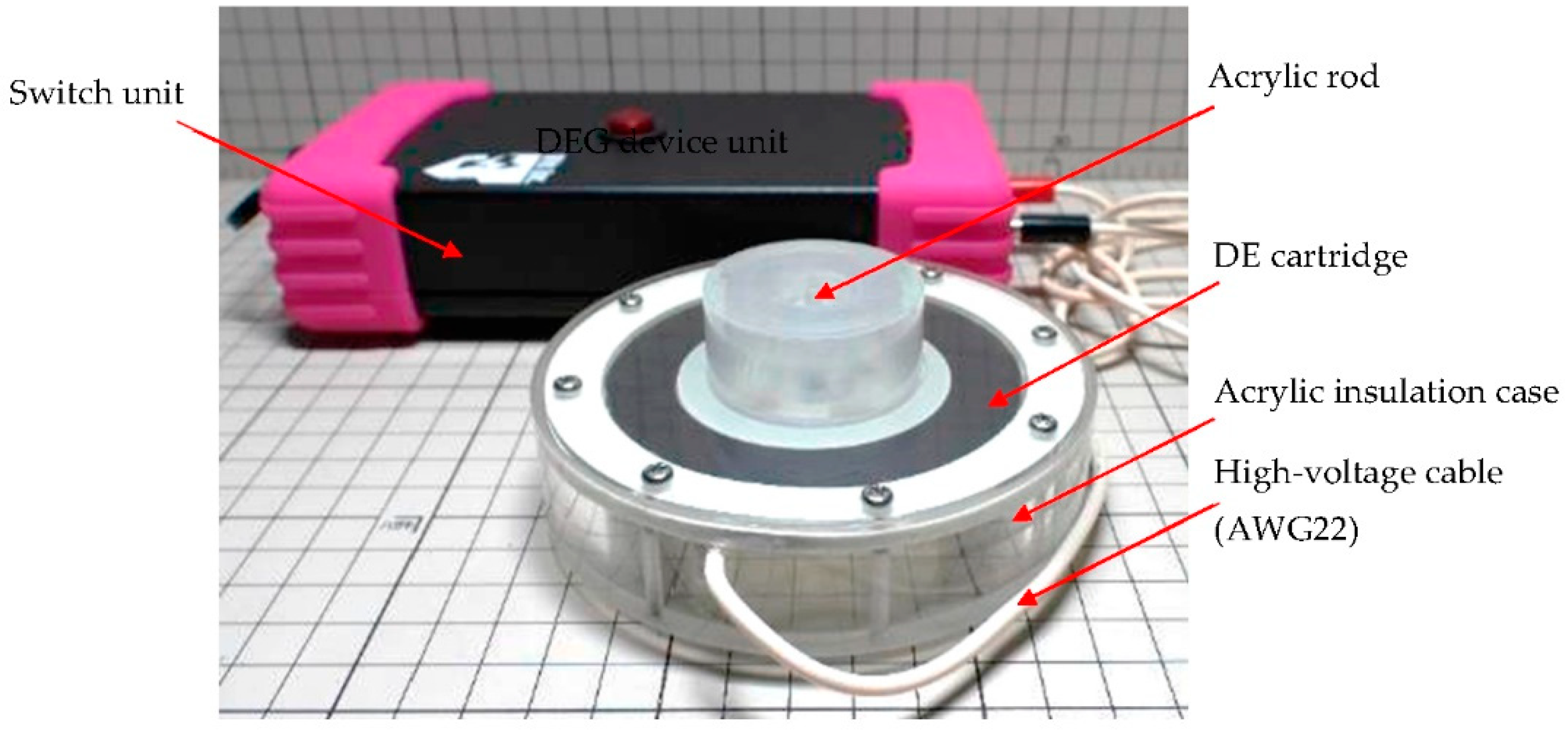
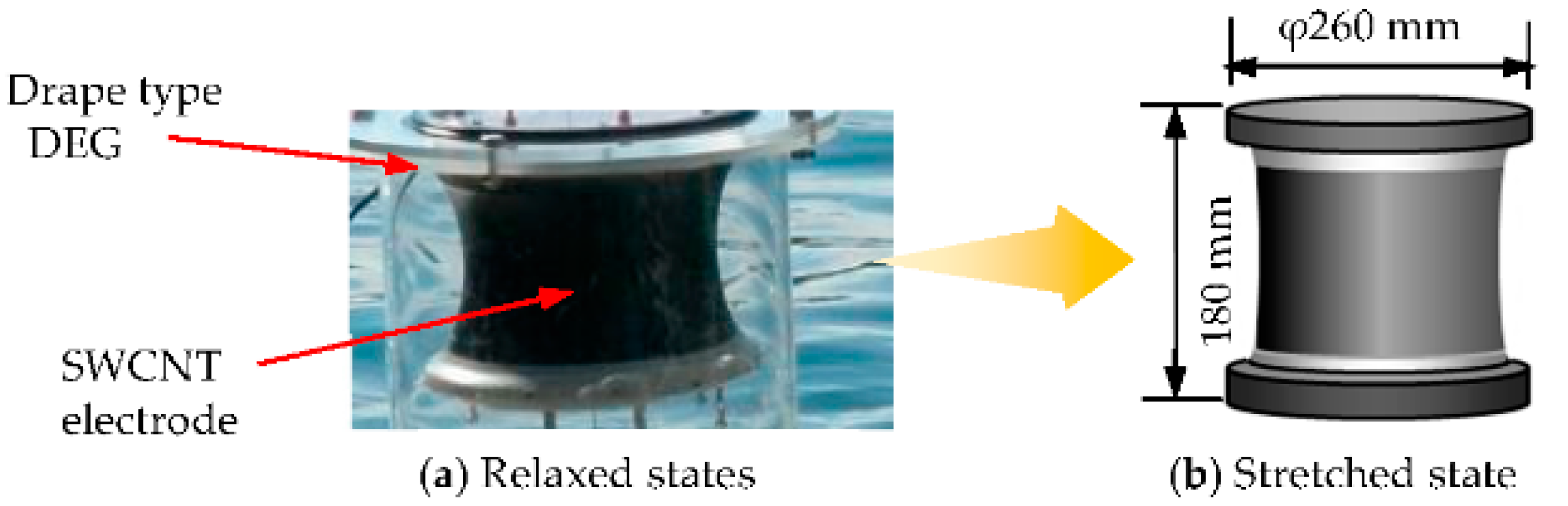
3.1. Manufacture of DE Cartridges and DEGs
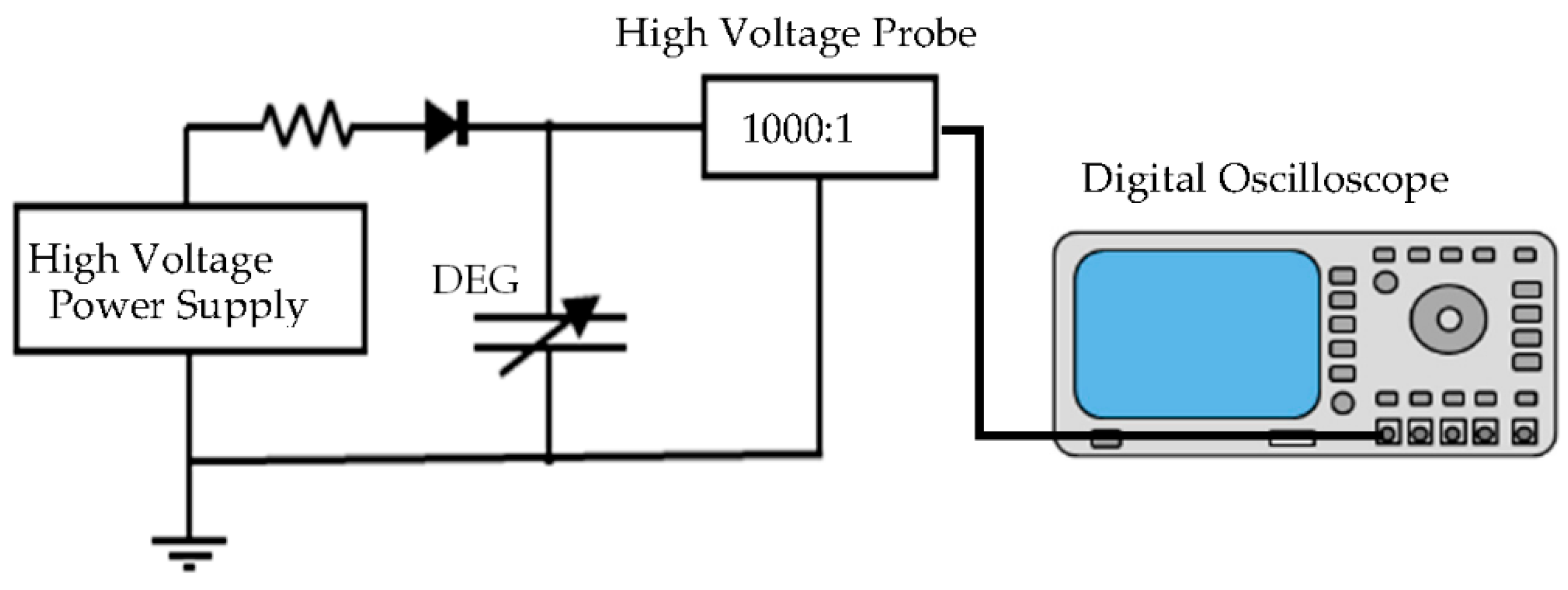
3.2. Measurement of the Amount of Power Generated by the Small DEG Device
- (1)
- The voltage (V2) between the upper and lower electrodes of the DEG in the contracted state can be measured for each wave frequency using a digital oscilloscope (see Figure 4).
- (2)
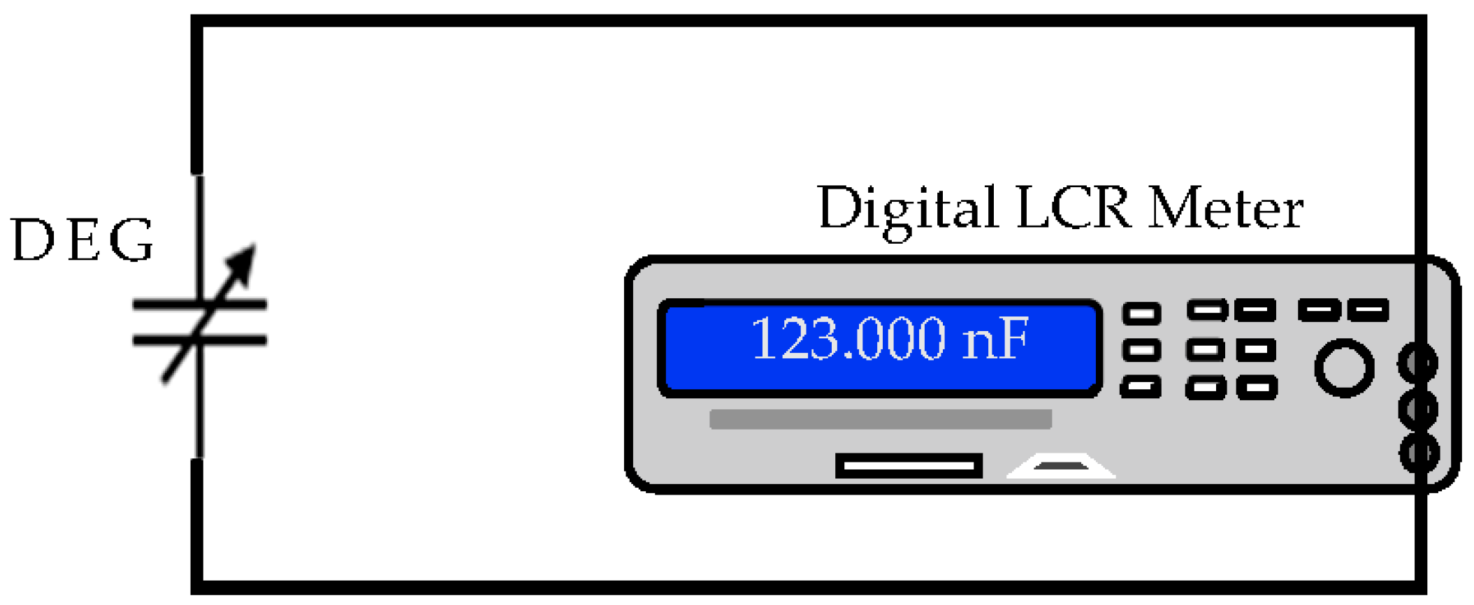
- The capacitance (C2) of the DEG in the contracted state is measured with a digital LCR meter (see Figure 5).
- (3)
- Using Equations (1) and (2) and the values of C2 and V2, the amount of energy generation can be calculated as follows:
- I.
- The relationship C1 = V2C2/Vb is derived from Equation (1).
- II.
- Next, by introducing C1 into the Equation (2), the generated electric energy can be obtained.E = 0.5VbV2C2 [(V2/Vb) − 1]
- III.
- Using Equation (4) and the values of C2 and V2, the energy generated at the frequency of each wave of the DEG can be calculated.
3.3. Examination/Improvement of a Step-Down Circuit for Small Power Generation Devices
- (1)
- MORNSUN 1DC/DC converterThe following two types of MORNSUN converters were examined.
- 1.
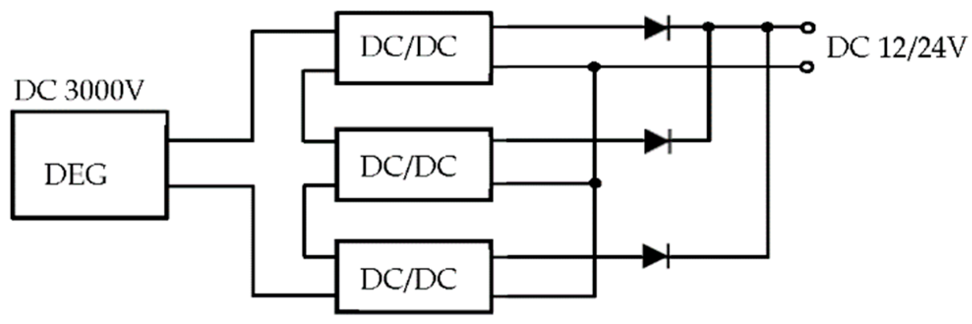
- 1000 V DC/DC converter (see Figure 6).
- Input voltage: 100 to 1000 V.
- Output voltage: 12 V, 24 V.
- Three DC/DC converters were connected in series and the maximum input voltage was set to 3000 V.
- The circuit method of the DC/DC converter is unknown due to non-disclosure.
- 2.
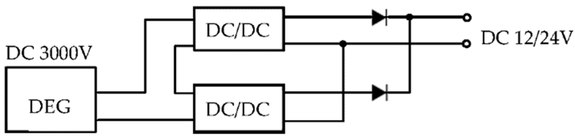
- 1500 V DC/DC converter (see Figure 7)
- Input voltage: 200 to 1500 V.
- Output voltage: 12 V, 24 V.
- Two DC/DC converters were connected in series and the maximum input voltage was set 3000 V.
- The circuit method of the DC/DC converter is unknown due to non-disclosure.
- (2)
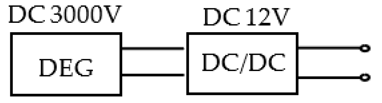
- Fairchild DC/DC converter (12 V output)A step-down circuit was created using a direct conversion IC for this converter (see Figure 8).
- (3)
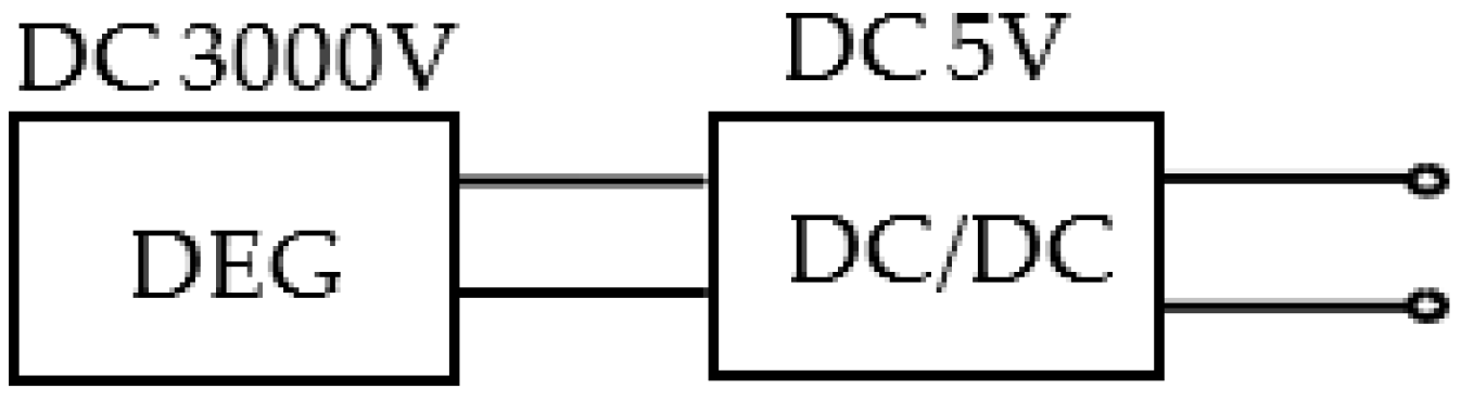
- Circuit using HOLTEK DC/DC converter IC (5 V output)The output from the small DEG device was stepped down to the rated input voltage of the DC/DC converter by a circuit using a capacitor, and then the voltage was made constant by using the DC/DC converter (see Figure 9).
- The efficiency of the DC/DC converter used is 85% or less (catalog value).
- (4)
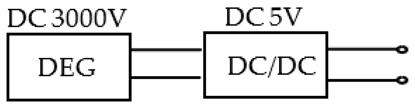
- TOREX DC/DC converterThe output from the small DEG device was stepped down to the rated input voltage of the DC/DC converter by a circuit using a capacitor, and then the voltage was made a constant by using a DC/DC converter (see Figure 10).
- The efficiency of the DC/DC converter used is 92% or less (catalog value).
- (5)
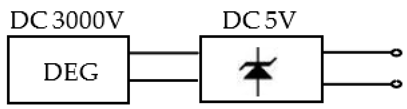
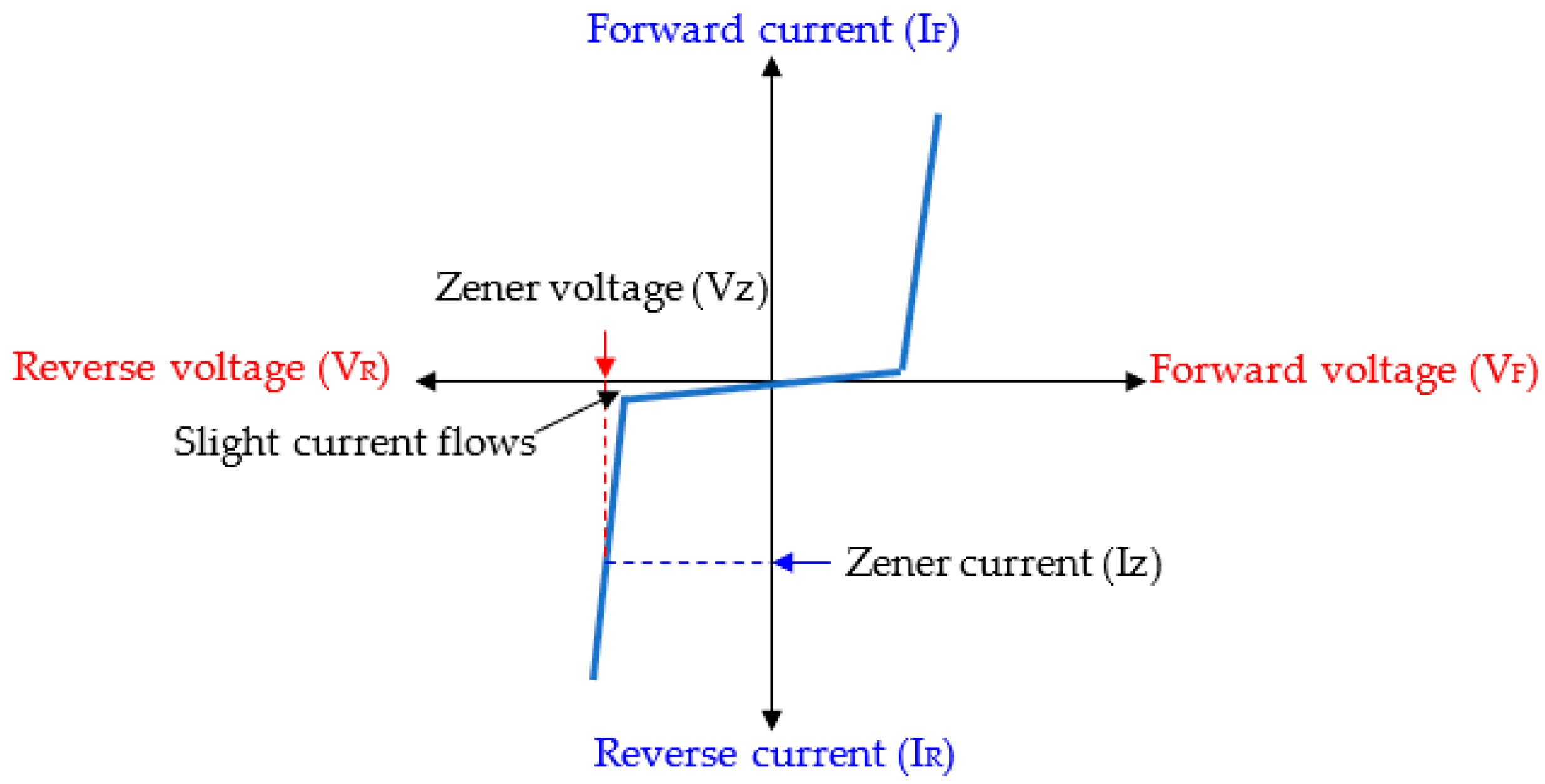
- Circuit using Zener diode (5 V output)The output from the small DEG device was stepped down to a few volts by a circuit using a capacitor, and then converted to a constant voltage using a Zener diode (see Figure 11).
- (6)
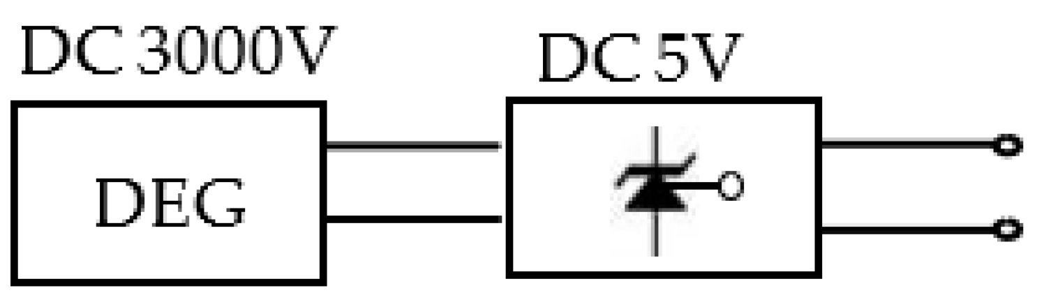
- Shunt regulator circuit with TI reference voltage IC (5 V output)The output from the small DEG device was stepped down to a few volts in a circuit using capacitors.After that, a constant voltage was set using a shunt regulator circuit using a reference voltage IC (see Figure 12).
- Uses TI reference voltage IC.
- Uses NEC reference voltage IC.
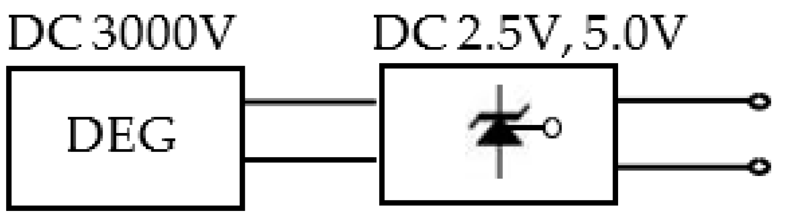
- (7)
- Shunt regulator circuit with TI reference voltage IC (2.5 V, 5 V output)The output from the small DEG device was stepped down by a few volts in a circuit using a capacitor, and then converted to a constant voltage using a reference voltage IC (see Figure 13).
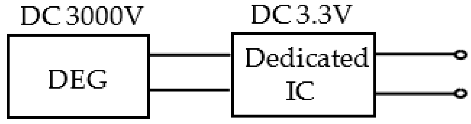
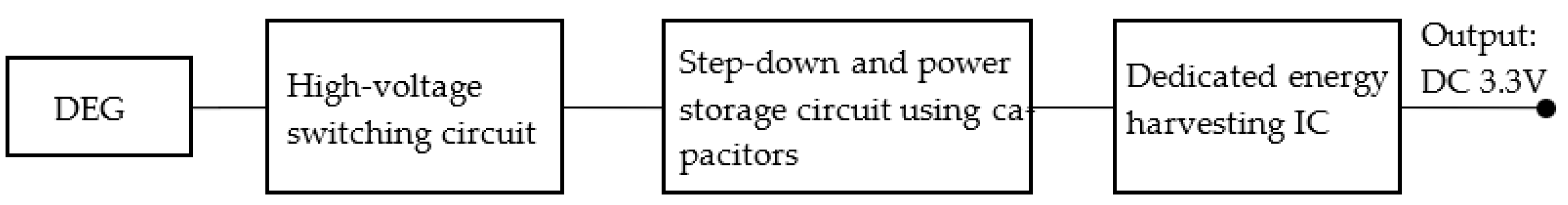
- (8)
- Circuit using a dedicated energy harvesting IC manufactured by Analog Devices (DC3.3 V)After stepping down the rated input voltage of the energy harvesting-dedicated IC in a circuit using a capacitor, the output from the small DEG device was stored and converted to a constant voltage using the energy harvesting-dedicated IC (see Figure 14).
3.4. Development of a Circuit That Can Charge a Secondary Battery
4. Results
4.1. Power Generation Performance of DEG
4.2. Examination of Step-Down Circuits for Small Power Generation Devices
4.2.1. MORNSUN DC/DC Converter
4.2.2. Fairchild DC/DC Converter
4.2.3. Circuit Using HOLTEK DC/DC Converter IC (5 V Output)
4.2.4. Circuit Using TOREX DC/DC Converter IC (5 V Output)
4.2.5. Circuit Using Zener Diode (5 V Output)
4.2.6. Shunt Regulator Circuit with TI Reference Voltage IC (5 V Output)
4.2.7. Shunt Regulator Circuit with TI Reference Voltage IC (2.5 V, 5 V Output)
4.2.8. Circuit Using an Energy Harvesting IC Manufactured by Analog Devices, Inc. (DC3.3 V)
4.3. A Circuit That Can Charge a Secondary Battery
- (1)
- To obtain an output of a stable voltage of 3.3 V by driving a small DEG about 20–30 times.
- (2)
- To optimize the voltage and current applied to the DE module, step-down circuit, regulator circuit, and power storage circuit.
5. Discussion
6. Conclusions
- A small DEG device using two circular DE cartridges with a diameter of 8 cm was able to generate 33.6 mJ of energy.
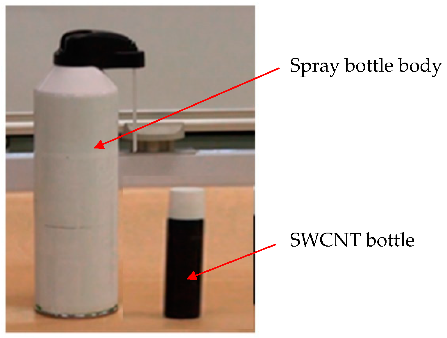
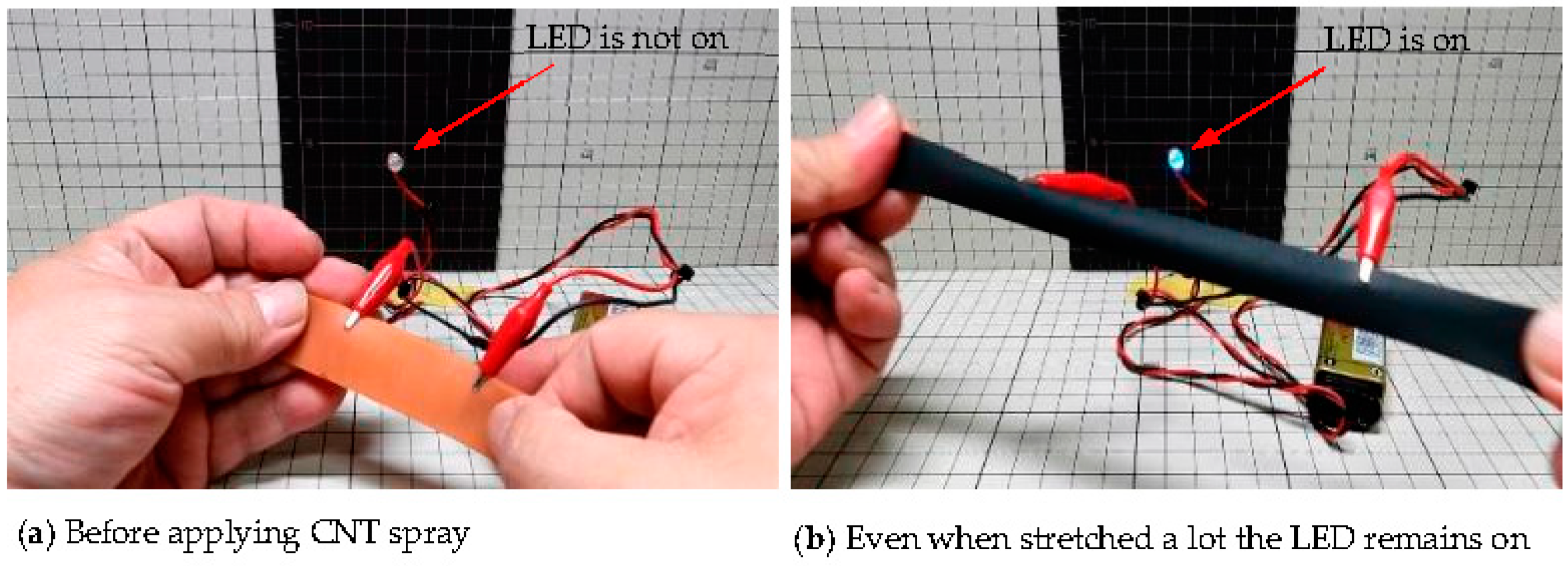
- At present, SWCNTs are the best electrode to be used for DE cartridges. However, they need to be well dispersed.
- Using SWCNT spray, it is possible to make electrodes more easily.
- Since the amount of energy generation is small and the output is intermittent in a small DEG, it is necessary to keep the energy consumption of each component low, such as the regulator circuit or the energy storage circuit. Therefore, it is important to use a circuit that can be driven with as few parts as possible.
- In this experiment, a film capacitor was used as the capacitor for a step-down circuit and a power storage circuit, but it seems that a more efficient power storage circuit could be realized by using a capacitor with lower internal resistance and less self-discharge.
Author Contributions
Funding
Acknowledgments
Conflicts of Interest
References
- Oguro, K.; Fujiwara, N.; Asaka, K.; Onishi, K.; Sewa, S. Polymer electrolyte actuator with gold electrodes. In Proceedings of the SPIE’s 6th Annual International Symposium on Smart Structures and Materials, Newport Beach, CA, USA, 1 March 1999; Volume 3669, pp. 64–71. [Google Scholar]
- Otero, T.F.; Sansiñena, J.M. Soft and wet conducting polymers for artificial muscles. Adv. Mater. 1998, 10, 491–494. [Google Scholar] [CrossRef]
- Osada, Y.; Okuzaki, H.; Hori, H. A polymer gel with electrically driven motility. Nature 1992, 355, 242–244. [Google Scholar] [CrossRef]
- Suzumori, K.; Nabae, H.; Asaka, K.; Horiuchi, T. Applying IPMC to soft robots. In Proceedings of the SPIE 11375, Electroactive Polymer Actuators and Devices (EAPAD) XXII, Online, 22 April 2020; p. 113750. [Google Scholar] [CrossRef]
- Pelrine, R.; Kornbluh, R.; Joseph, J.; Hetdit, R.; Chiba, S. High-field defomation of elasomeric dielectrics for actuators. In Proceedings of the 6th SPIE Symposium on Smart Structure and Materials, Newport Beach, CA, USA, 1 March 1999; Volume 3669, pp. 149–161. [Google Scholar]
- Pelrine, R.; Chiba, S. Review of artificial muscle approaches. In Proceedings of the Third International Symposium on Mi-cromachine and Human Science, Nagoya, Japan, 15–18 May 1992; pp. 1–9. [Google Scholar]
- Chiba, S.; Waki, M. The Challenge of Controlling a Small Mars Planes. Solar Planets and Exoplanets; InTech: London, UK, 2022. [Google Scholar]
- Li, W.; Zhu, S.; Ohyama, K.; Chiba, S.; Waki, M. Mechanical properties and viscoelasticity of dielectric elastomers. In Proceedings of the Materials and Mechanics Conference, Japan Society of Mechanical Engineers, Sapporo, Japan, 7–9 October 2017. [Google Scholar] [CrossRef]
- Chiba, S.; Kobayashi, M.; Qu, T.; Zhu, S.; Waki, M.; Takeshita, M.; Ohyama, K. Examination of factors to improve the elongation and output of dielectric elastomers. In Proceedings of the SPIE 12042, Electroactive Polymer Actuators and Devices (EAPAD)XXIV, Online, 20 April 2022; Volume 1204211. [Google Scholar] [CrossRef]
- Chiba, S.; Waki, M. Application to dielectric elastomer materials, power assist products, artificial muscle drive system. In Next-Generation Polymer/Polymer Development, New Application Development and Future Prospects; Technical Information Association: Tokyo, Japan, 2019; Section 3, Chapter 4, ISBN-10: 4861047757; ISBN-13: 978-4861047756. [Google Scholar]
- Chiba, S.; Waki, M.; Takeshita, M.; Uejima, M.; Arakawa, K. Dielectric elastomer using CNT as an electrode. In Proceedings of the SPIE Electroactive Polymer Actuators and Devices (EAPAD) XXII, Online, 22 April 2020. [Google Scholar] [CrossRef]
- Hajiesmaili, E.; Clarke, D. Dielectric elastomer actuators. J. Appl. Phys. 2021, 129, 151102. [Google Scholar] [CrossRef]
- Hu, P.; Madsen, J.; Skov, A.L.L. Super-stretchable silicone elastomer applied in low voltage actuators. In Proceedings of the SPIE 11587, Electroactive Polymer Actuators and Devices (EAPAD) XXIII, Online, 22 March 2021; Volume 1158715. [Google Scholar] [CrossRef]
- Hu, P.; Huang, Q.; Madsen, J.; Skov, A.L. Soft silicone elastomers with no chemical cross-linking and unprecedented softness and stability. In Proceedings of the SPIE 11375, Electroactive Polymer Actuators and Devices (EAPAD) XXII, Online, 24 April 2020; Volume 1137517. [Google Scholar] [CrossRef]
- Majidi, C. Enhancing the permittivity of dielectric elastomers with liquid metal. In Proceedings of the SPIE 11375-15, Electroactive Polymer Actuators and Devices (EAPAD) XXII, Online, 22–26 April 2020; Volume 113750Q. [Google Scholar] [CrossRef]
- Liebscher, H.; Tahir, M.; Wiessner, S.; Gerlach, G. Effect of barium titanate particle filler on the performance of polyurethane-based dielectric elastomer actuators. In Proceedings of the Electroactive Polymer Actuators and Devices (EAPAD) XXIV, Long Beach, CA, USA, 6 March–11 April 2022; Volume 1204210. [Google Scholar] [CrossRef]
- Romasanta, L.; López-Manchado, M.; Verdejo, R.I. Increasing the performance of dielectric elastomer actuators: A review from the materials perspective. Prog. Polym. Sci. 2015, 51, 188–221. [Google Scholar] [CrossRef]
- Kumamoto, H.; Hayashi, T.; Yonehara, Y.; Okui, M.; Nakamura, T. Development of a locomotion robot using deformable dielectric elastomer actuator without pre-stretch. In Proceedings of the SPIE 11375, Electroactive Polymer Actuators and Devices (EAPAD) XXII, Oline, 22 April 2020; Volume 1137509. [Google Scholar] [CrossRef]
- Hayat, S.; Ahmed, S.; Zeb, M.; Khan, Q.M.; Khan, S.M.; Usama, M.; Najam, Z. Design of efficient power supply for the proper operation of bio-mimetic soft lens. Int. J. Adv. Comput. Sci. Appl. 2020, 11, 7. [Google Scholar] [CrossRef]
- Chiba, S.; Waki, M.; Takeshita, M.; Yoshizawa, T. Improvement measures for components of dielectric elastomers for heavy duty uses such as robots and power assist devices. Adv. Theor. Comput. Phys. 2021, 4, 241–249. [Google Scholar] [CrossRef]
- Albuquerque, F.B.; Shea, H.R. Effect of humidity, temperature, and elastomer material on the lifetime of silicone-based dielectric elastomer actuators under a constant DC electric field. In Proceedings of the SPIE 11375, Electroactive Polymer Actuators and Devices (EAPAD) XXII, Online, 22–26 April 2020; Volume 113751E. [Google Scholar] [CrossRef]
- Kornbluh, R.D.; Pelrine, R.; Prahlad, H.; Wong-Foy, A.; McCoy, B.; Kim, S.; Eckerle, J.; Low, T. From boots to buoys: Promises and challenges of dielectric elastomer energy harvesting. In Proceedings of the SPIE Electroactive Polymer Actuators and Devices (EAPAD), San Diego, CA, USA, 7–10 March 2011; Volume 7976, p. 79605. [Google Scholar] [CrossRef]
- Chiba, S.; Waki, M.; Ono, K.; Hatano, R.; Taniyama, Y.; Tanaka, S.; Okada, E.; Ohyama, K. Challenge of creating high performance dielectric elastomers. In Proceedings of the SPIE2021 (Smart Structures and Materials Symposium and its 23rd Electroactive Polymer Actuators and Devices (EAPAD) XXIII, Online, 22 March 2021; Volume 115871T, pp. 1157–1162. [Google Scholar] [CrossRef]
- Chiba, S.; Waki, M.; Jiang, C.; Takeshita, M.; Uejima, M.; Arakawa, K.; Ohyama, K. The possibility of a high-efficiency wave power generation system using dielectric elastomers. Energies 2021, 14, 3414. [Google Scholar] [CrossRef]
- Xu, L.; Gu, G. Bioinspired venus flytrap : A dielectric elastomer actuated soft gripper. In Proceedings of the 24th International Conference on Mechanical and Machine Vision in Practices (M2VIP), Auckland, New Zealand, 18 December 2017. [Google Scholar] [CrossRef]
- Youn, J.-H.; Jeong, S.M.; Hwang, G.; Kim, H.; Hyeon, K.; Park, J.; Kyung, K.-U. Dielectric elastomer actuator for soft robotics applications and challenges. Appl. Sci. 2020, 10, 640. [Google Scholar] [CrossRef]
- Thongking, W.; Wiranata, A.; Minaminosono, A.; Mao, Z.; Maeda, S. Soft robotic gripper based on multi-layers of dielectric elastomer actuators. J. Robot. Mechatron. 2021, 33, 968–974. [Google Scholar] [CrossRef]
- Ashby, J.; Rosset, S.; Henke, E.-F.M.; Anderson, I.A. One soft step: Bio-inspired artificial muscle mechanisms for space applications. Front. Robot. AI 2022, 8, 792831. [Google Scholar] [CrossRef]
- Rosset, S.; Anderson, I.A. Squeezing more juice out of dielectric elastomer generators. Front. Robot. AI 2022, 9, 825148. [Google Scholar] [CrossRef] [PubMed]
- Chiba, S.; Waki, M.; Wada, T.; Hirakawa, Y.; Masuda, K.; Ikoma, T. Consistent ocean wave energy harvesting using electroactive polymer (dielectric elastomer) artificial muscle generators. Appl. Energy 2012, 104, 497–502. [Google Scholar] [CrossRef]
- Chiba, S.; Hasegawa, K.; Waki, M.; Kurita, S. An experimental study on the motion of floating bodies arranged in series for wave power generation. J. Mater. Sci. Eng. A7 2017, 11–12, 281–289. [Google Scholar] [CrossRef][Green Version]
- Koh, S.J.A.; Zhao, X.; Suo, Z. Maximal energy that can be converted by a dielectric elastomer generator. Appl. Phys. Lett. 2009, 94, 262902. [Google Scholar] [CrossRef]
- Huang, J.; Shian, S.; Suo, Z.; Clarke, D.R. Maximizing the energy density of dielectric elastomer generators using equi-biaxial loading. Adv. Funct. Mater. 2013, 23, 5056–5061. [Google Scholar] [CrossRef]
- Vertechy, R.; Papini, G.P.; Rosati, P.; Fontana, M. Reduced model and application of inflating circular diaphragm dielectric elastomer generators for wave energy harvesting. J. Vib. Acoust. Trans. ASME 2015, 137, 11–16. [Google Scholar] [CrossRef]
- Bortot, E.; Gei, M. Harvesting energy with load-driven dielectric elastomer annular membranes deforming out-of-plane. Extreme Mech. Lett. 2015, 5, 62–73. [Google Scholar] [CrossRef]
- Moretti, G.; Fontana, M.; Vertechy, R. Parallelogram-shaped Dielectric Elastomer Generators: Analytical model and Experimental Validation. J. Intell. Mater. Syst. Struct. 2015, 26, 740–751. [Google Scholar] [CrossRef]
- Brochu, P.; Yuan, W.; Zhang, H.; Pei, Q. Dielectric elastomers for direct wind-to-electricity2009, power generation. In Proceedings of the ASME Conference on Smart Materials, Adaptive Structures and Intelligent System, Oxnard, CA, USA, 21–23 September 2009. [Google Scholar]
- McKay, T.G.; O’Brien, B.M.; Calius, E.; Anderson, I.A. Soft generators using dielectric elastomers. Appl. Phys. Lett. 2011, 98, 1–3. [Google Scholar] [CrossRef]
- Anderson, I.; Gisby, T.; McKay O’Brienl, B.; Calius, E. Multi-functional dielectric elastomer artificial muscles for soft and smart machines. J. Appl. Phys. 2012, 112, 041101. [Google Scholar] [CrossRef]
- Kessel, V.; Wattez, R.; Bauer, P. Analyses and comparison of an energy harvesting system for dielectric elastomer generators using a passive harvesting concept: The voltage-clamped multi-phase system. In Proceedings of the SPIE Smart Structures and Materials + Nondestructive Evaluation and Health Monitoring, International Society for Optics and Photonics, Sandiego, CA, USA, 8–12 March 2015; p. 943006. [Google Scholar]
- Chiba, S.; Waki., M. Innovative power generator using dielectric elastomers (creating the foundations of an environmentally sustainable society). Sustain. Chem. Pharm. 2020, 15, 100205. [Google Scholar] [CrossRef]
- Chiba, S.; Hasegawa, K.; Waki, M.; Fujita, K.; Ohyama, K.; Zhu, S. Innovative elastomer transducer driven by karman vortices in water flow. J. Mater. Sci. Eng. A7 2017, 5–6, 121–135. [Google Scholar] [CrossRef][Green Version]
- Di, K.; Bao, K.; Chen, H.; Xie, X.; Tan, J.; Shao, Y.; Li, Y.; Xia, W.; Xu, Z.; Shiju, E. Dielectric elastomer generator for electromechanical energy conversion: A mini review. Sustainability 2021, 13, 9881. [Google Scholar] [CrossRef]
- Mitsumasa, I.; Miyazaki, T.; Iida, M. Estimation of cumulative output energy of oscillating water colum wave energy converter considering power take off damping. In Proceedings of the ASME 2020 39th International Conference on Ocean, Offshore and Arctic En-Gineers, Online, 3 August 2020. OMAE-19172. [Google Scholar]
- Arena, F.; Daniele, L.; Fiamma, V.; Fontana, M.; Malara, G.; Moretti, G.; Romolo, A.; Papini, G.P.R.; Scialò, A.; Vertechy, R. Field experiments on dielectric elastomer generators integrated on a U-OWC wave energy converter. In Proceedings of the ASME 2018 37th International Conference on Ocean, Offshore and Arctic Engineering, Madrid, Spain, 17–22 June 2018; Volume 51319. [Google Scholar] [CrossRef]
- Moretti, G.; Papini, G.P.R.; Daniele, L.; Forehand, D.; Ingram, D.; Vertechy, R.; Fontana, M. Modelling and testing of a wave energy converter based on dielectric elastomer generators. Proc. R. Soc. A Math. Phys. Eng. Sci. 2019, 475, 20180566. [Google Scholar] [CrossRef]
- Zhou, J.; Jiang, L.; Khayat, R. Dynamic analysis of a tunable viscoelastic dielectric elastomer oscillator under external excitation. Smart Mater. Struct. 2016, 25, 025005. [Google Scholar] [CrossRef]
- Jean-Mistral, C.; Basrour, S.; Chaillout, J.-J. Dielectric polymer: Scavenging energy from human motion. In Proceedings of the Electroactive Polymer Actuators and Devices (EAPAD), San Diego, CA, USA, 10–13 March 2008; Volume 6927, pp. 369–378. [Google Scholar]
- Yurchenko, D.; Lai, Z.; Thomson, G.; Val, D.V.; Bobryk, R. Parametric study of a novel vibro-impact energy harvesting system with dielectric elastomer. Appl. Energy 2017, 208, 456–470. [Google Scholar] [CrossRef]
- Chiba, S.; Waki, M.; Fujita, K.; Song, Z.; Ohyama, K.; Zhu, S. Recent progress on soft transducers for sensor networks. In technologies and eco-innovation towards sustainability II. Spring Nat. 2019, 1, 285–298. [Google Scholar] [CrossRef]
- Jiang, C.; Chiba, S.; Waki, M.; Fujita, K.; Moctar, O. Investigation of a Novel Wave Energy Generator Using Dielectric Elastomer. In Proceedings of the ASME 2020 39th International Conference on Ocean, Offshore and Arctic Engineers, Online, 3–7 August 2020. OMAE-18106. [Google Scholar] [CrossRef]
- Chiba, S.; Waki, M.; Jiang, C.; Fujita, K. Possibilities for a Novel Wave Power Generator Using Dielectric Elastomers. In Proceedings of the ASME 2020 39th International Conference on Ocean, Offshore and Arctic Engineers, Online, 3–7 August 2020. OMAE-18464. [Google Scholar] [CrossRef]
- Hata, K.; Futaba, D.N.; Mizuno, K.; Namai, T.; Yumura, M.; Iijima, S. Water-Assisted Highly Efficient Synthesis of Impurity-Free Single-Walled Carbon Nanotubes. Science 2004, 306, 1362–1364. [Google Scholar] [CrossRef] [PubMed]


| Type of Electrode | Energy Obtained (mJ) |
|---|---|
| Carbon black | 274 |
| Multi-walled carbon nanotube (MWCNT) | 445 |
| Single-walled carbon nanotube (SWCNT) | 630 |
| High crystalline SWCNT | 819 |
Publisher’s Note: MDPI stays neutral with regard to jurisdictional claims in published maps and institutional affiliations. |
© 2022 by the authors. Licensee MDPI, Basel, Switzerland. This article is an open access article distributed under the terms and conditions of the Creative Commons Attribution (CC BY) license (https://creativecommons.org/licenses/by/4.0/).
Share and Cite
Chiba, S.; Waki, M. Possibility of a Portable Power Generator Using Dielectric Elastomers and a Charging System for Secondary Batteries. Energies 2022, 15, 5854. https://doi.org/10.3390/en15165854
Chiba S, Waki M. Possibility of a Portable Power Generator Using Dielectric Elastomers and a Charging System for Secondary Batteries. Energies. 2022; 15(16):5854. https://doi.org/10.3390/en15165854
Chicago/Turabian StyleChiba, Seiki, and Mikio Waki. 2022. "Possibility of a Portable Power Generator Using Dielectric Elastomers and a Charging System for Secondary Batteries" Energies 15, no. 16: 5854. https://doi.org/10.3390/en15165854
APA StyleChiba, S., & Waki, M. (2022). Possibility of a Portable Power Generator Using Dielectric Elastomers and a Charging System for Secondary Batteries. Energies, 15(16), 5854. https://doi.org/10.3390/en15165854