Article

Numerical Investigations of a Non-Uniform Stator Dihedral Design Strategy for a Boundary Layer Ingestion (BLI) Fan

1
National Key Laboratory of Science and Technology on Aero-Engine Aero-Thermodynamics, Beihang University, Beijing 100191, China
2
Research Institute of Aero-Engine, Beihang University, Beijing 100191, China
3
School of Energy and Power Engineering, Beihang University, Beijing 100191, China
*
Author to whom correspondence should be addressed.
Energies 2022, 15(16), 5791; https://doi.org/10.3390/en15165791
Submission received: 6 June 2022 / Revised: 15 July 2022 / Accepted: 17 July 2022 / Published: 10 August 2022
(This article belongs to the Special Issue Flow and Heat Transfer in Turbomachinery)

Abstract

:
A distributed propulsion system has the advantage of saving 5–15% fuel burn through ingesting the fuselage boundary layer of an aircraft by fan or compressor. However, due to boundary layer ingestion (BLI), the fan stage will continuously operate under serious inlet distortion. This will lead to a circumferentially non-uniform flow separation distribution on the stator blade suction surface along the annulus, which significantly decreases the fan’s adiabatic efficiency. To solve this problem, a non-uniform stator dihedral design strategy has been developed to explore its potential of improving BLI fan performance. First, the stator full-annulus blade passages were divided into blade dihedral design regions and baseline design regions on the basis of the additional aerodynamic loss distributions caused by BLI inlet distortion. Then, to find the appropriate dihedral design parameters, the full-annulus BLI fan was discretized into several portions according to the rotor blade number and the dihedral design parameter investigations for dihedral depth and dihedral angle were conducted at the portion with the largest inflow distortion through a single-blade-passage computational model. The optimal combinational dihedral design parameter (dihedral depth 0.3, dihedral angle 6 deg) was applied to the blade passages with notable flow loss which were mainly located in the annulus positions from −120 to 60 degrees suffering from inlet distortion, while the blades in the low-loss annulus locations were unchanged. In this way, a non-uniform stator dihedral design scheme was achieved. In the end, the effectiveness of the non-uniform stator dihedral design was validated by analyzing the internal flow fields of the BLI fan. The results show that the stator dihedral design in distorted regions can increase the inlet axial velocity and reduce the aerodynamic load near the blade trailing edge, which are beneficial for suppressing the flow separations and reducing aerodynamic loss. Specifically, compared with the baseline design, the non-uniform stator dihedral design has achieved a reduction of aerodynamic loss of about 7.7%. The fan stage has presented an improvement of adiabatic efficiency of about 0.48% at the redesigned point without sacrificing the total pressure ratio. In the entire operating range, the redesigned fan has also shown a higher adiabatic efficiency than the baseline design with no reduction of the total pressure ratio, which provides a probable guideline for future BLI distortion-tolerant fan design.

1. Introduction

In recent years, the concept of distributed propulsion configuration has attracted considerable attention to meet the growing environmental goals of commercial aircraft with reduced fuel burn, noise, and emissions [1,2]. The distributed propulsion configuration generally utilizes fans to ingest the boundary layers on the aircraft fuselage [3,4], which has the advantage of saving between 5–15% in fuel consumption [5,6,7,8,9]. However, the boundary layer ingestion (BLI) would cause inlet distortions for the fans. The non-uniform inflow working condition usually generates additional losses in BLI fans and brings new problems for the design of fan blades.
The additional losses caused by BLI inlet distortion have been evaluated on different conceptual aircraft. Uranga et al. [10] assessed the aerodynamic benefit of conceptual commercial aircraft D8 and pointed out that under cruise conditions with a lift coefficient of 0.64, the efficiency of the BLI fans would be reduced by 1.5%. Kim et al. [11] simulated the flows in propulsor fans on NASA N3-X conceptual aircraft. The results showed that compared with the fan adiabatic efficiency under clean inflow conditions, the BLI inlet distortion will lead the fan efficiency to drop by more than 4%. Additionally, a more serious efficiency decrease of about 6% resulting from BLI inlet distortion, appeared in the fans of the Boeing N + 2 Blended Wing Body (BWB) aircraft [12]. The above results suggest that the additional losses in BLI fans are significant and large.
The reasons and distributions of large additional losses in BLI fans have been investigated in previous studies. Due to additional loss generation, Mennicken et al. [13] conducted a predesigned-methodology study on an ultra-high-bypass-ratio fan with BLI inlet distortion and demonstrated that under the influence of BLI inflow distortion, the axial velocity in the distorted region of the inlet was reduced by up to 15% compared with that in the undistorted region. Cousins et al. [14] made attempts to obtain a distortion-tolerant fan design. The results indicated that at the design point, the attack angle at the rotor inlet fluctuated seriously along circumferential and radial directions, and the rotor blade performances in the distorted region deteriorated as a result of suffering from the high blade load. It can be inferred from the above research that the BLI inflow distortion condition will inevitably raise the blade load, which will aggravate the local aerodynamic losses and decrease the rotor aerodynamic performance. For the downstream stator, Giuliani et al. [15] studied the interaction between the inlet and fan rotor and noted that when the distortion propagated through the rotor, it showed a large impact on the stator aerodynamic performance. Florea et al. [16] carried out an aerodynamic analysis on the integration of embedded engine inlet and fan stage. The results showed that after the distorted inflow passed through the rotor, the distortion intensity was almost not weakened. The research results on the BLI fan stator mean that the stator blades will also continuously operate under the distorted-inflow condition and the losses in the stator will inevitably increase.
On the other hand, for the additional loss distributions in rotor and stator blade passages, Li et al. [17] found that both tip-leakage loss and hub-separation loss were distributed non-uniformly along the circumferential direction in the BLI fan rotor. Gunn et al. [18] investigated the influence of BLI inlet distortion on the flow fields and aerodynamic losses in the fan. They noted that there were non-uniform swirls and radial angle distributions at the inlet of the stator, which led to a non-uniform distribution of corner separation loss in the stator. It can be deduced that the BLI distorted inflows have resulted in spatially non-uniform flow structures and additional loss distributions in the rotor and stator blade passages, which significantly decreases the fan aerodynamic performance.
In order to reduce the adverse impact of BLI distorted inflow on the fan aerodynamic performance, an effective fan blade design strategy that aims to reduce the additional loss in the BLI fan is necessary. The research work conducted on blade design has demonstrated that reducing the flow separation loss in the BLI fan stator is probably a good way to improve the fan efficiency effectively [19]. In this situation, it is essential to find a good way to suppress the flow separations in the stator to reduce the additional loss and further improve the aerodynamic performance of the BLI fan.
Previous research has shown the blade dihedral design to be effective with regard to the reduction of separation loss [20,21,22]. Specifically, the investigations on the dihedral blade can be mainly divided into two parts: mechanism and application research. Regarding the explanation of loss reduction mechanisms of the dihedral blade, Wang et al. [23] studied the influences of positive and negative dihedral blades on the flow fields in a cascade. They found that when using positive dihedral blades, the static pressure at the upper and lower endwalls increased and the static pressure at the midspan decreased. Then, with the effect of such a pressure gradient, the low-momentum fluids in the corner region migrated toward midspan and the flow separations near the endwalls were eliminated. Weingold et al. [24] described the mechanism of the dihedral blade using the lift line model. For positive dihedral blades, the endwall streamtubes near the blade suction surface expanded near the leading edge and shrank near the trailing edge, which reduced the peak Mach number and diffusion rate near the endwall. In this situation, the boundary layer separations were delayed. With respect to the applications of the dihedral blade in fans and compressors, Breugelmans et al. [25] studied the effects of lean or dihedral blades on the internal flow fields and found that the appropriate dihedral or lean angle could control the accumulations of secondary flows near the endwall and reduce the associated losses. Takahashi et al. [26] carried out experimental and numerical investigations on the endwall flows in a dihedral cascade passage. They noted that the blade load near the endwall was reduced and the intensity of separation flow attenuated compared with that of a straight-stacking blade. Gümmer et al. [27] applied the positive dihedral and positive sweep to the design of a highly loaded transonic compressor stator blade. The result indicated that the serious separation flows near the stator hub were suppressed, and the separation loss was reduced significantly. Gallimore et al. [28,29] also explored the effectiveness of dihedral and sweep in a low-speed and high-speed multistage compressor blade design. They concluded that the dihedral could improve the through flow capacity and increase the compressor efficiency. Based on the above investigations, the results indicate that the dihedral blade can effectively suppress the secondary flow accumulation near the endwall, delay the boundary layer separation and reduce the aerodynamic loss.
In view of the superior performance of the blade dihedral design in suppressing flow separations and the non-uniform distributions of additional separation loss in the BLI fan stator, a spatially non-uniform stator dihedral design strategy is developed in this work to better control the stator aerodynamic loss and enhance the BLI fan performance. The motivation is to explore the potential for performance improvement of the non-uniform stator dihedral design and provide some probable guidelines for a future high-performing BLI fan design.

2. Study Case and Numerical Method
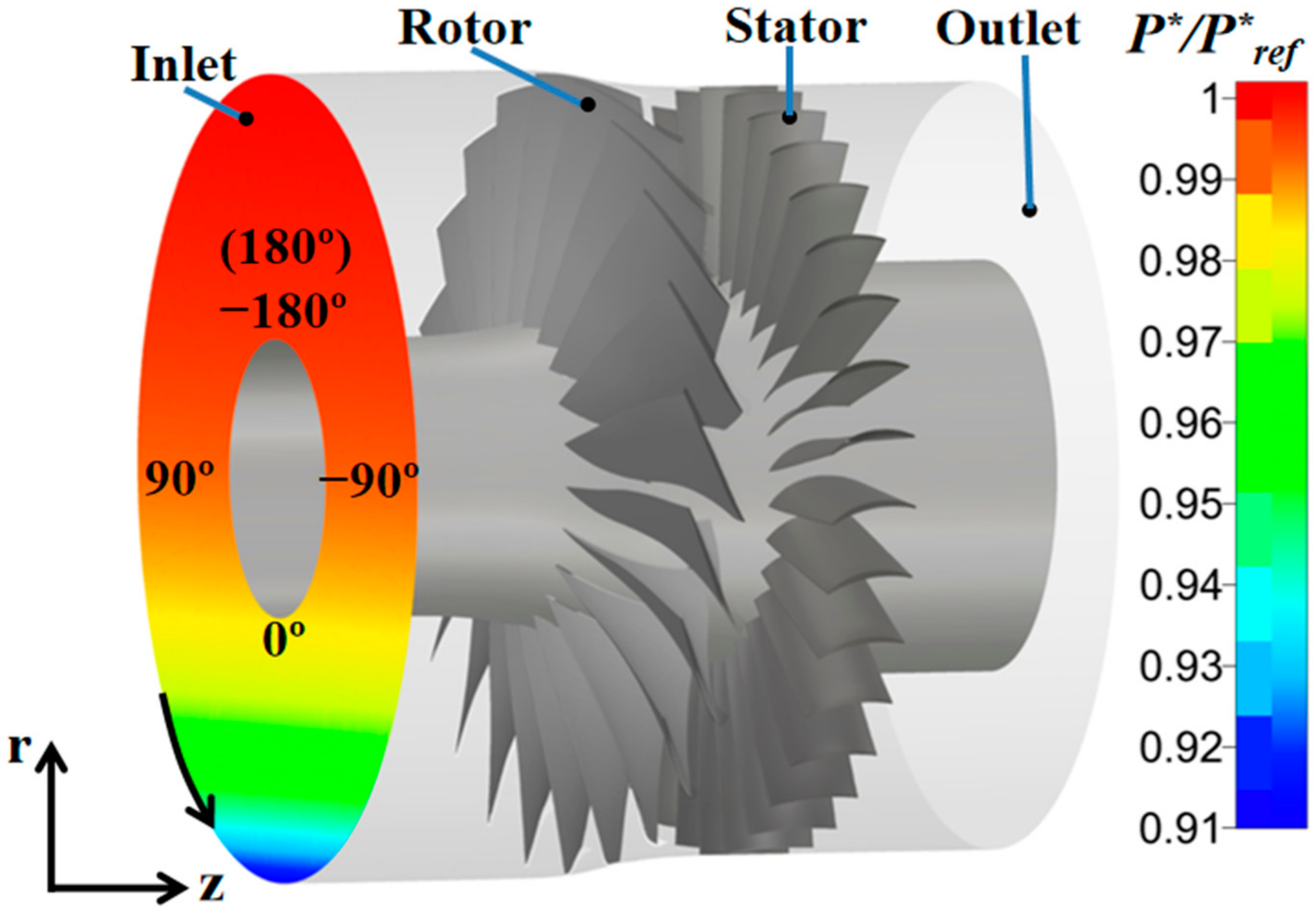
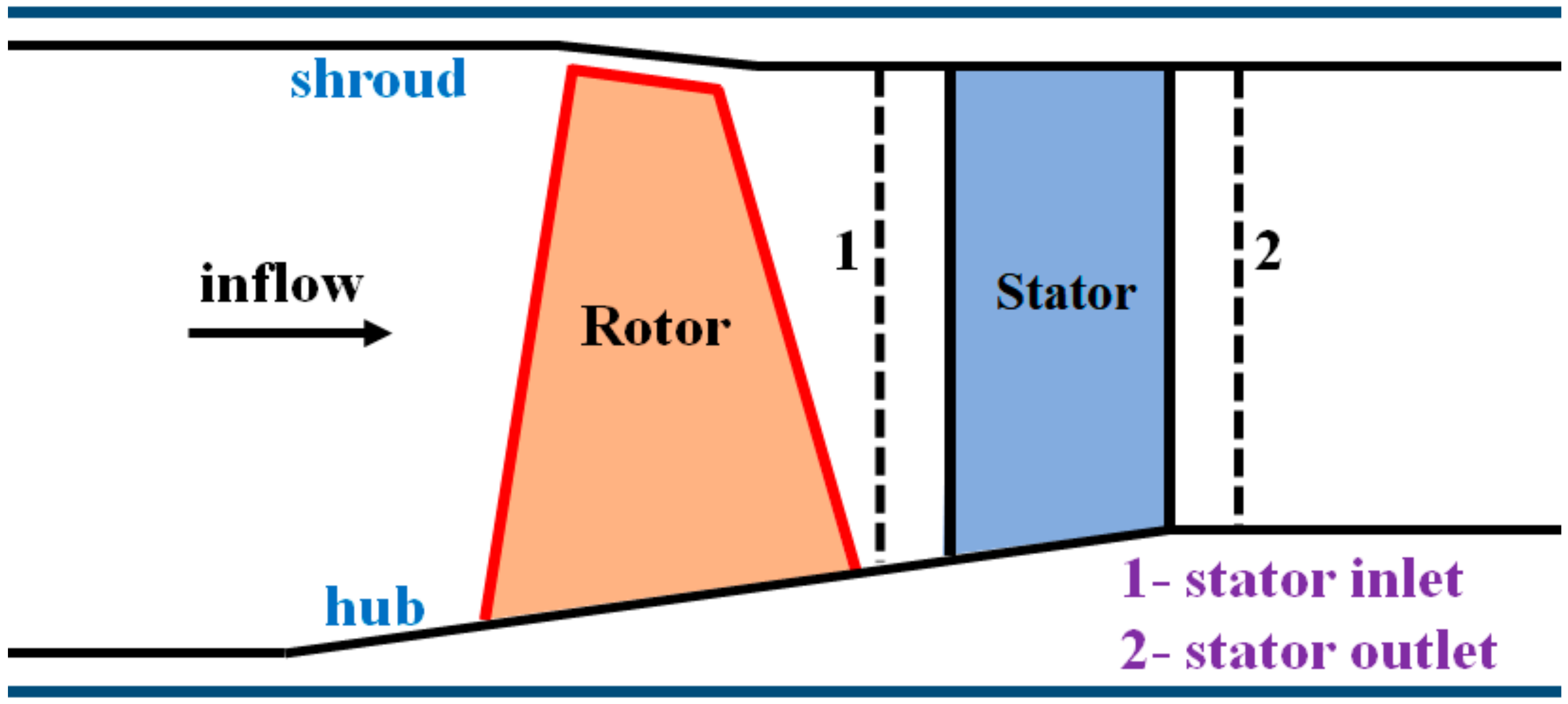
2.1. Study Case

The research object of this study is the transonic axial-flow fan NASA Stage 67. Along the annulus, it is composed of 22 multiple-circular-arc rotor blades and 34 controlled-diffusion stator blades. The rotor speed is 16,043 rpm and the tip inlet relative Mach number is 1.38. The running tip clearance of the fan rotor is 0.5 mm. Additionally, the mass flow is 33.25 kg/s and the stage total pressure ratio is close to 1.63. Other main design parameters are listed in Table 1, and more information is provided in reference [30].
A meridional geometry of NASA Stage 67 is presented in Figure 1. The computational domain extends approximately 3 times the axial chord length of the rotor midspan upstream of the rotor leading edge and 2.5 times the axial chord length of the stator midspan downstream of the stator trailing edge. Dashed lines 1 and 2 represent stator inlet and outlet respectively, which are located at about 30% axial chord length of the midspan from the stator leading and trailing edges.

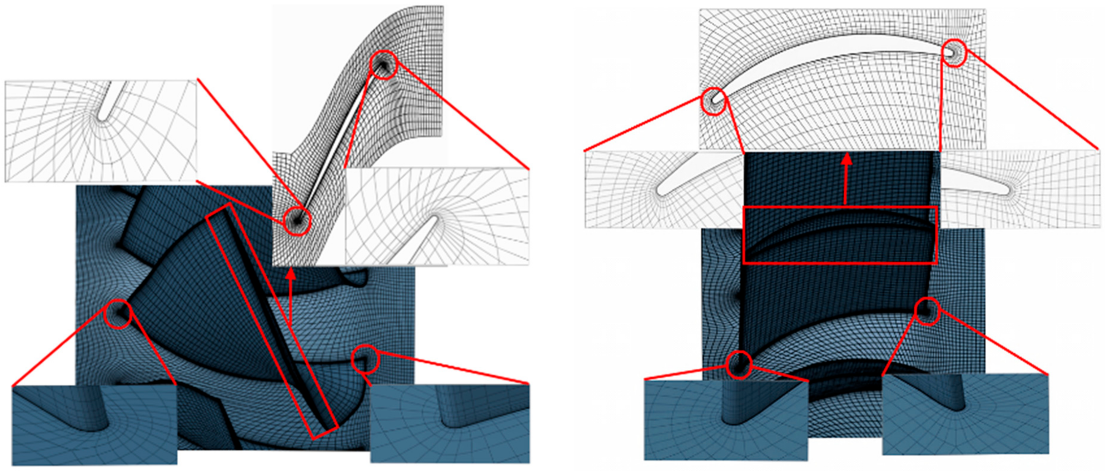
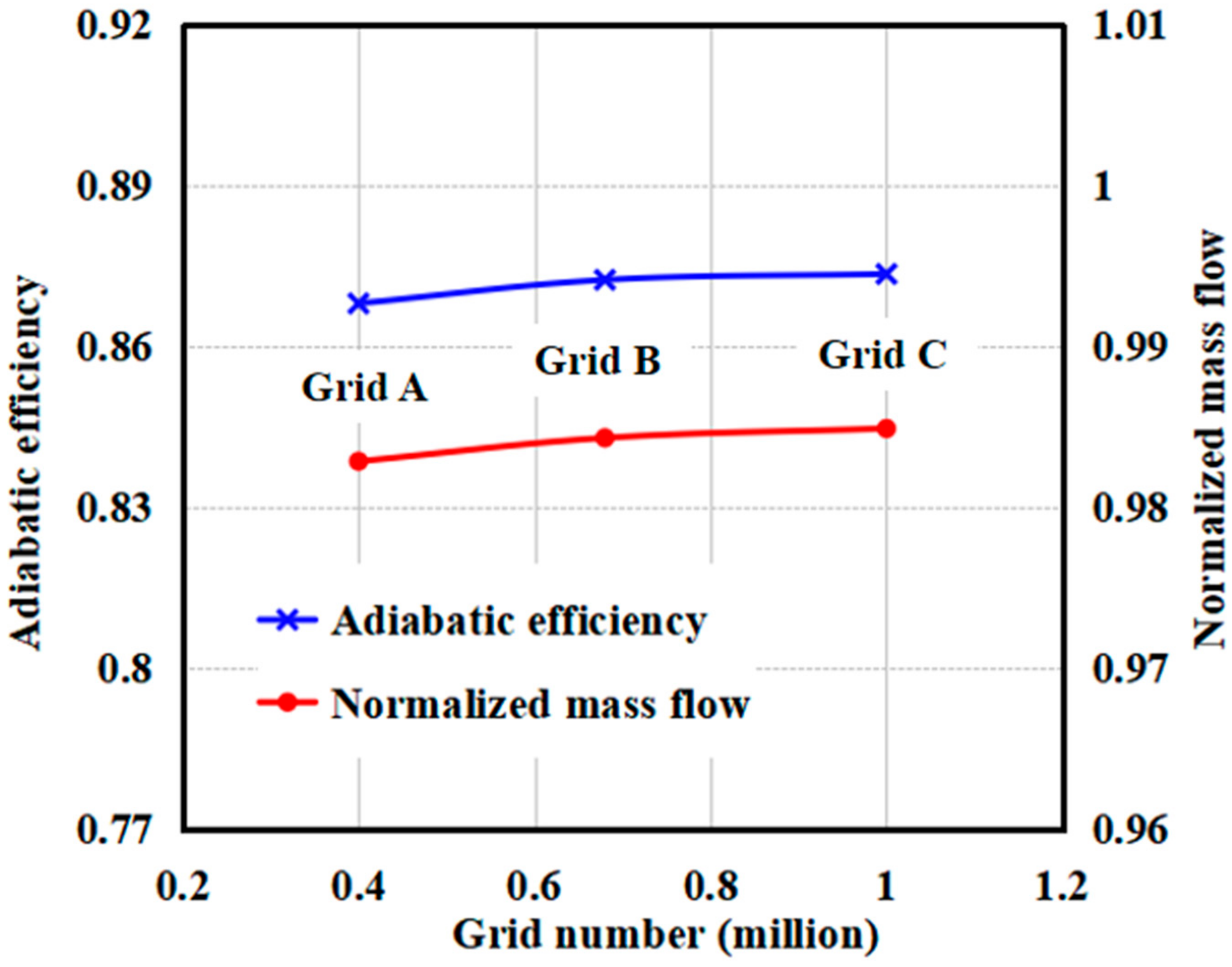
2.2. Computational Methods
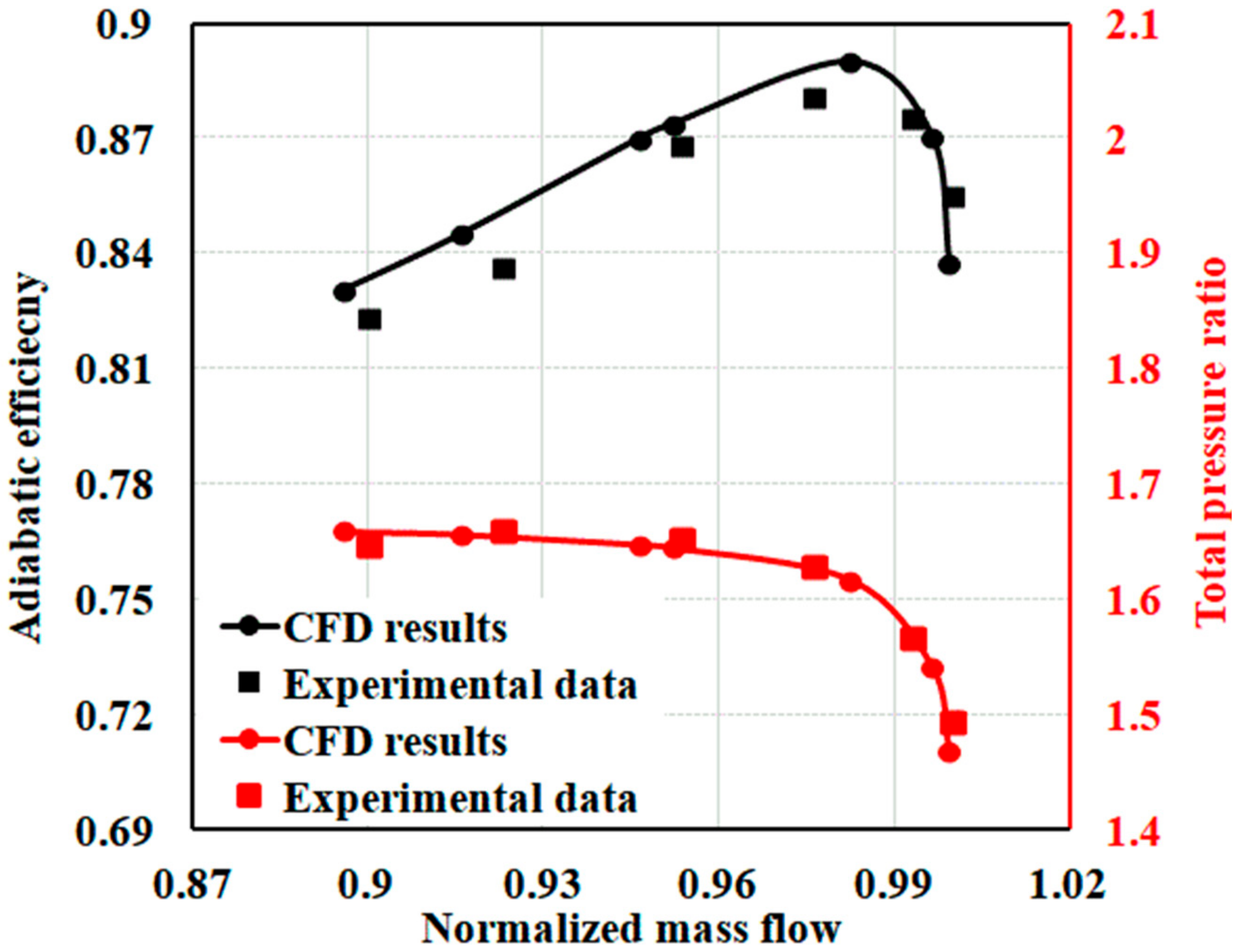
The commercial flow solver NUMECA FINE-Turbo EURANUS is selected in this work to solve the three-dimensional compressible Reynolds-averaged Navier–Stokes (RANS) equations using a finite volume method. The spatial discretization of the equations is based on the second-order precision center difference scheme. The time term is discretized using the fourth-order Runge–Kutta method. In addition, some accelerating techniques, such as the multigrid approach, local time stepping, and the implicit residual smoothing method are also employed to obtain the flow-field solutions. The one-equation Spalart–Allmaras (SA) turbulence model [31] is selected in this study to resolve the eddy viscosity, which has been widely used to predict the internal flows in turbomachines [32,33].
To capture the influences of BLI inlet distortion, three-dimensional full-annulus unsteady numerical simulations have been performed, and the entire computational domain is shown in Figure 2. At the inlet of computational domain, total pressure and total temperature are given, and the flow direction is assumed to be axial. At the domain outlet, averaged static pressure is imposed. In the computational domain, the working fluid is chosen as a perfect gas, and all solid walls are set as adiabatic and no-slip.
A total pressure distortion is imposed at the inlet as shown in Figure 2. Specifically, the distribution of the total pressure can be expressed as:
P i n * ( r ) P r e f * = 1 5 π arctan [ 7 ( r + 0.5 D ) D ] + 0.911 r D [ 0.5 , 0.5 ] ,
where D denotes the diameter of the inlet, r represents the vertical position of the inlet, and P r e f * references the total pressure, which is the atmospheric pressure.
The total pressure distribution at the inlet due to BLI inflow distortion selected in this study has key features which are reported in the open literature [12,18]. There is a smooth velocity variation in the radial direction and a low-momentum fluid region is located at the bottom of the fan inlet. In addition, the distortion intensity is defined as:
D A = ( P m a x * P m i n * ) / P a v e * ,
where P m a x * and P m i n * denote the maximum and minimum total pressure on the inlet plane, respectively. P a v e * is the averaged total pressure. The distortion intensity in this work is 0.092.
For the time setting of unsteady simulations, the implicit dual time stepping method is used to solve the equations, in which the pseudo-time derivation is included for the time integration scheme. Specifically, the angular position number is set as 30, which means that one rotor blade takes 30 time steps passing through a pitch with a physical time step of 5.7 × 10⁻⁶ s. In addition, within a physical time step, there are 20 pseudo-time iterations with a CFL (Courant Friedrichs Lewy) number of 3 which can provide a stable convergence. For a full-annulus simulation, there are 660 physical time steps (22 rotor blades) and 13,200 pseudo-time iterations.
For the computational grid, an O4H-type structured mesh system is selected to discretize the blade passage. O-type grids are distributed around the blade surface. H-type grids are applied in other regions, except that the butterfly grids are utilized in the blade tip clearance region. Additionally, the locally normalized wall distance y+ is less than 5 for all the simulations. The meshes for the fan rotor and stator blades are described in Figure 3.
A grid independence study has been conducted by using a single-blade-passage computational model at near peak efficiency conditions. Three different mesh sizes which are 0.4, 0.68, and 1 million grid points named Grid A, Grid B, and Grid C, respectively, are considered. The results for adiabatic efficiency and normalized mass flow of the fan with a variety of grid numbers are shown in Figure 4. Specifically, as the grid number changes from Grid A to Grid B, the computed adiabatic efficiency is increased by about 0.5%, while as the grid number changes from Grid B to Grid C, the computed adiabatic efficiency is only increased by 0.13% which is lower than 0.5%. Meanwhile, for the normalized mass flow rate, when the mesh changes from Grid A to Grid B, the computed mass flow has an increment of 0.14%. As the mesh changes from Grid B to Grid C, the computed mass flow increment decreases to 0.06% which is much lower than 0.14%. To balance the numerical accuracy and computational time, Grid B is selected in this study, and the grid number for a full-annulus simulation is about 18.7 million.

2.3. CFD Validation

In order to check the reliability of the numerical method in this work, the single-blade-passage steady numerical simulations are carried out based on the measured operating tip clearance (0.5 mm) of the rotor. The numerical results have been compared with the available experimental data [30] at clean inflow conditions as shown in Figure 5. The adiabatic efficiency predicted by the CFD tool is in agreement with the experimental results, except that the computed adiabatic efficiency is slightly higher than the experimental data. Furthermore, the total pressure ratio predicted by the numerical simulation also agrees well with the experimental results.
Further, to check the ability of the numerical tool to capture the flow-field details, Figure 6 gives a comparison of absolute velocity contours on the blade-to-blade plane in the stator passage at a 50% span between the numerical results and experimental data. The velocity isolines of the numerical and experimental results have similar variational trends from the stator leading edge to the trailing edge, although the velocity isolines of the numerical results near the trailing edge change slightly faster than those of the measured results. Moreover, compared with the experimental data, the flow separation regions near the trailing edge are predicted well, except that the separation area is slightly larger. Through the comparisons of numerical and experimental results, it can be suggested that the CFD tool is capable of providing reliable predictions on aerodynamic performance and flow-field details for a transonic fan.

3. Problem Descriptions

Because of the features of the BLI distortion profile, the low-momentum fluids will exist at the bottom of the rotor inlet, which has lower axial velocity and static pressure compared with the fluids at other annulus positions. The low axial velocity of the fluids at the bottom of the inlet will increase the local blade incidence angle. Moreover, since the low-momentum fluids have lower static pressure, a swirl and radial flow will form at the rotor inlet, which will affect the incidence angle distribution. In such a situation, a circumferentially and radially non-uniform incidence distribution will present at the rotor inlet, leading to the associated rotor blades operating under deteriorated working conditions. In the meantime, the circumferentially and radially non-uniform flow structures will not vanish after they pass through the rotor blade and will result in non-uniform inflows for the downstream stator blade. The distribution of incidence angle at the stator inlet is given in Figure 7. It can be observed that the BLI inflow distortion has resulted in a large high-incidence area at the stator inlet, which will cause some of the stator blades to operate in critical off-design conditions and make the intensity of corner separation vary at different annulus positions.
Figure 8 describes the comparisons of total pressure loss distributions at 10%, 50%, and 90% span under BLI inlet distortion and clean inflow conditions at near peak efficiency points. The definition of stator total pressure loss is shown below:
P t l o s s = P i n * P o u t * P i n * P i n ,
where P i n * and P o u t * denote the total pressures at the inlet and outlet separately, and Pin represents the inlet static pressure. It can be observed that compared with clean inflow conditions, the BLI inlet distortion has resulted in a severe total pressure loss near the blade tip, while the negative effects of inflow distortion are weakened at the hub and mid-span regions. The results indicate that compared with clean inflow conditions, the additional losses due to BLI inlet distortion mainly exist in the stator blade tip region. Moreover, it is also noted that from −120 to 60 deg annulus locations, the total pressure loss near the tip under the BLI inlet distortion condition is much higher than that under the clean inflow condition. Therefore, the dihedral design is only implemented in the spanwise fractions higher than 50% blade height, covering from −120 to 60 deg annulus positions where the rotor blade is moving from the distorted region to the undistorted region. For other annulus positions, the stator blades are not changed.

4. Non-Uniform Stator Dihedral Design

There are two parts to this section. First, the dihedral design method is introduced which mainly includes the baseline stator blade parameterization and manipulation of dihedral modification. Second, the key design parameters of the non-uniform dihedral stator blade are discussed.

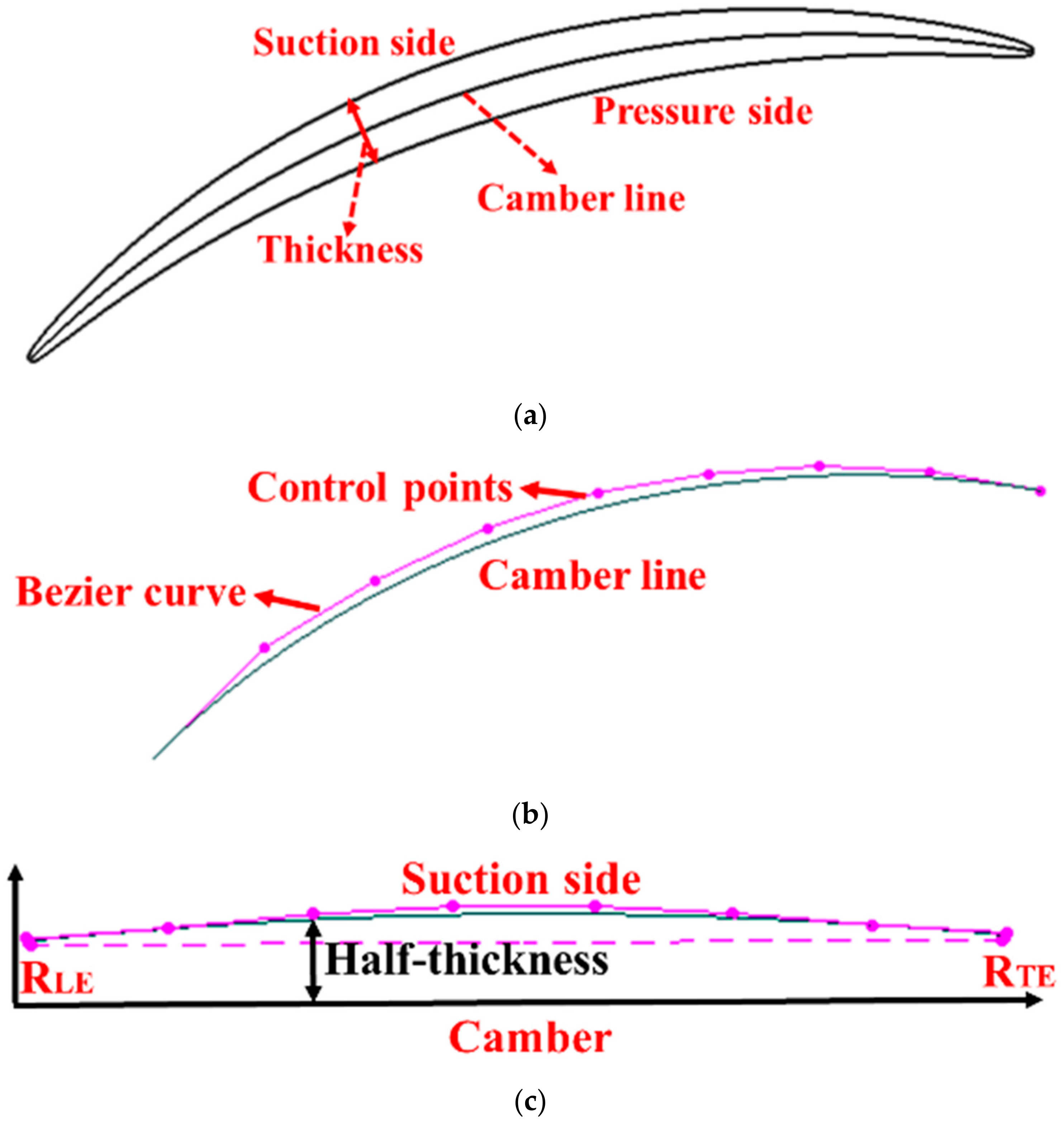
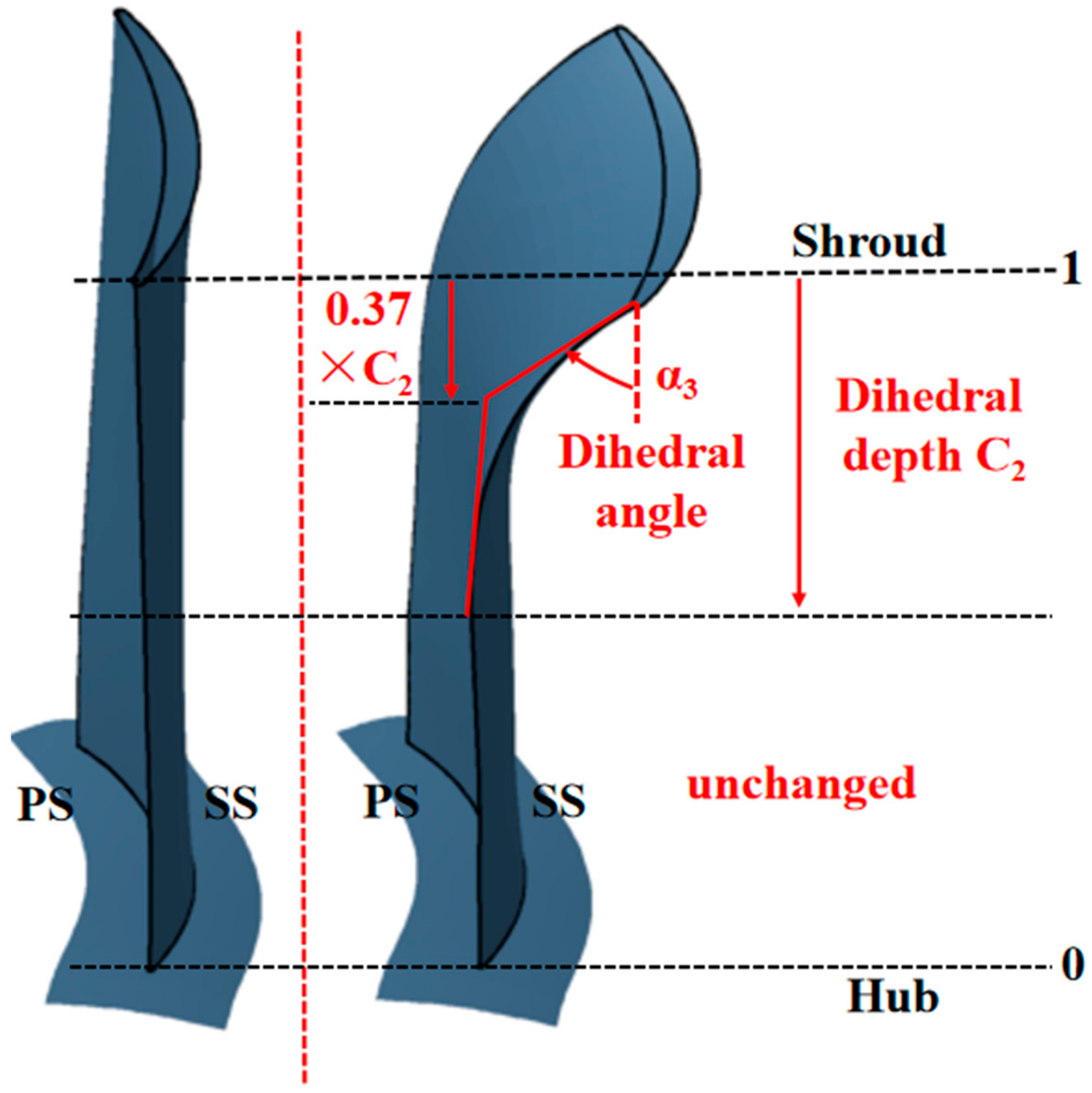
4.1. Stator Blade Parameterization

The parameterization of the stator blade was performed through the n-parameter Bezier curve, and the definition of the Bezier function is shown below:
P ( t ) = i = 0 n P i B i , n ( t ) t [ 0 , 1 ] ,
where Pi is the coordinate of the control point in the Cartesian coordinate system. Bi,n(t) is the Bernstein function and is defined as follows:
P i = ( x i , y i ) ,
B i , n ( t ) = n ! i ! n i ! t i ( 1 t ) n i , i = 0 , 1 , 2 , , n .
The stator blade was divided into 21 blade airfoils from hub to shroud equally, and every blade airfoil could be presented through a camber line, suction surface, and pressure surface. The blade airfoil parameterization adopted the way of imposing the blade airfoil thickness distribution on the camber as shown in Figure 9. The parameterization of the camber line of the blade airfoil was finished through an eight-parameter Bezier curve. There are eight control points on the Bezier curve which were distributed evenly from the leading edge to the trailing edge. Based on the airfoil thickness distribution, the parameterization of suction and pressure surfaces were also performed through an eight-parameter Bezier curve. In addition, both the leading and trailing edges of blade airfoils were rounded. After blade airfoil parameterization, the 21 blade airfoils from hub to shroud established a three-dimensional blade by stacking the gravity center of each airfoil.
To define the blade dihedral design, Figure 10 is the schematic graph of tangential variation of the stacking line which is composed of upper and lower Bezier curves and a straight line in the middle. For each Bezier curve, there are three control points to manipulate its shape. In the figure, α1 and α3 represent dihedral angles on the lower and upper endwalls, respectively. C1 and C2 represent dihedral depths from lower and upper endwalls separately. The shape of the stacking line is mainly controlled based on values of dihedral depths and dihedral angles. In addition, α2 is the inclination angle of the middle straight line. P1 and P2 are the fractional factors defining the locations of the second control point of lower and upper Bezier curves. With the control of the stacking line, the blade airfoils move along the normal direction of the chord. If the angle between the blade pressure surface and the endwall is acute, it is called the positive dihedral blade. In this paper, all the dihedral angles of redesigned blades are positive.
To clearly describe the dihedral blade, Figure 11 compares the differences between the baseline design and the dihedral design. For the dihedral design, the blade was modified by changing the values of the dihedral depth C2 and the dihedral angle α3. The other control parameters are consistent with the baseline stator blade. Note that the baseline stator blade is not a straight blade, and has a dihedral depth C2 of 0.78 and a dihedral angle α3 of 1.6 deg.

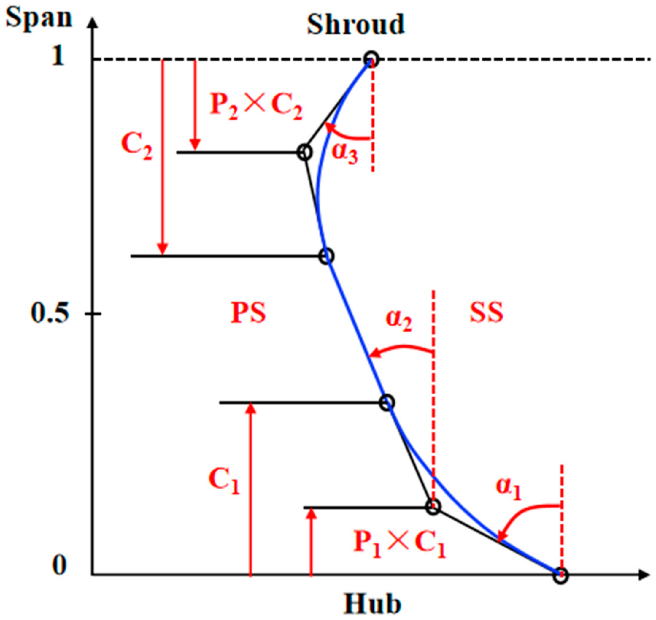
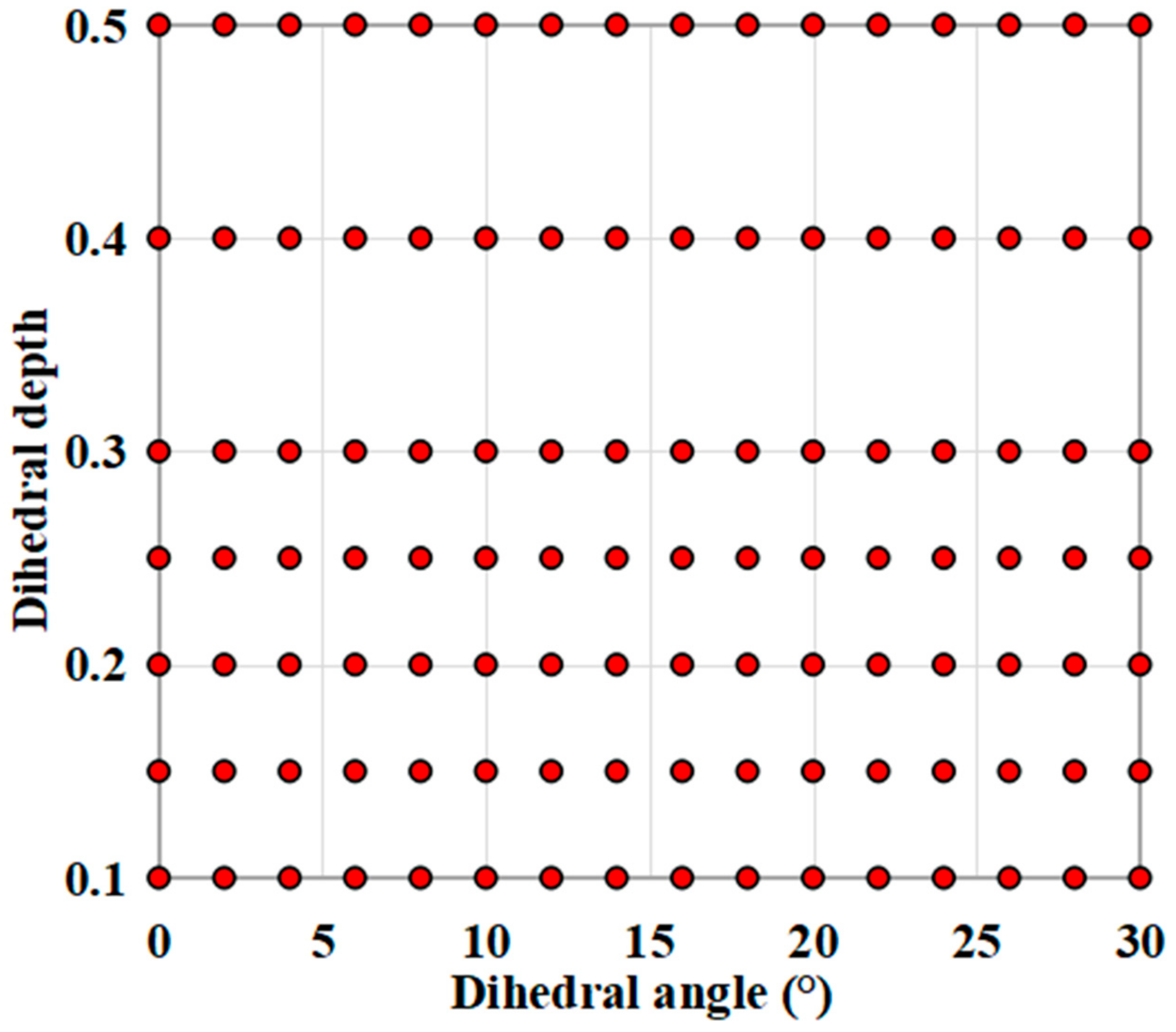
4.2. Dihedral Design Scheme

Since the inflow distortion was not notably eliminated after passing through the rotor blade, the stators still suffered from a circumferentially and radially non-uniform inflow. In this situation, for the stator blades at different annulus positions, the corresponding dihedral design parameters may also be different. Specifically, the full-annulus stator blade passages were divided into dihedral design regions and baseline design regions. Subsequently, to explore the appropriate dihedral design parameters and reduce computational time consumption, the full-annulus BLI fan was discretized into several portions according to the rotor blade number. The dihedral design parameter investigations were conducted at the portion with the largest inflow distortion (P1, marked by the red line in Figure 12) through a single-blade-passage computational model. The blade passage P1 was selected because it suffered from the most serious inflow distortion, and the additional aerodynamic loss in the stator was notable. Specifically, the effects of dihedral depths and dihedral angles on stator loss and fan stage performance were studied. The optimal dihedral depth and angle were used to implement non-uniform dihedral designs for the BLI fan stator.
Figure 13 presents the numerical simulation scheme of stator dihedral design. A total number of seven dihedral depths were selected, which were 0.1, 0.15, 0.2, 0.25, 0.3, 0.4, and 0.5. For each dihedral depth, there were 16 dihedral angles ranging from 0 to 30 deg with an interval of 2 deg. Finally, there were 112 research samples in total.
The influences of dihedral depth and dihedral angle on stator loss at near-peak efficiency points are reported in Figure 14. First, for different dihedral depths, the same total pressure loss could be achieved through varying the dihedral angles, as shown by isolines in the plot. Then, with the same dihedral depth, as the dihedral angle increased from 0 deg, the total pressure loss decreased initially and increased afterward. Therefore, there was a minimum loss for each dihedral depth due to the combined effects of separation loss and the loss generated in the process of the boundary layer migrating towards the midspan [23]. Specifically, as the dihedral angle increased, the separation loss reduced, but the loss caused by the boundary layer migration increased.
Since the influences of dihedral depth and dihedral angle on the stator loss have been discussed, the effects of dihedral depth and dihedral angle on fan stage efficiency at near peak efficiency point are further described as shown in Figure 15. The legend (Δη) represents the efficiency variation of the dihedral design relative to the maximum efficiency of the baseline design. It can be seen from Figure 15a that with the same dihedral depth, as the dihedral angle increases, the efficiency increases first and then decreases. Therefore, there is an optimal dihedral angle with each dihedral depth. The optimal combinational dihedral design parameters (dihedral depth/dihedral angle) are marked with a black line in Figure 15a.They are 0.1/16 deg, 0.15/12 deg, 0.2/8 deg, 0.25/8 deg, 0.3/6 deg, 0.4/6 deg, and 0.5/4 deg. These combinational dihedral design parameters can achieve approximately the same adiabatic efficiency improvement. In this situation, the combinational dihedral design parameter 0.3/6 deg is selected and used for stator dihedral design under inflow conditions such as P1 blade passage.
Further, as the dihedral depth is fixed at 0.3, the effect of different dihedral angles on the fan efficiency was investigated and the results are given in Figure 15b. The dihedral angle varied from 6 deg to 12 deg and the fan efficiency only shows a slight decrease of about 0.03%, which means that the fan efficiency was not sensitive to the variation of the dihedral angle when the dihedral depth was 0.3. Since the distortion intensities at other annulus locations of the full-annulus BLI fan were all lower than the distortion intensity of the P1 blade passage, the required dihedral angle for the blades in these annulus locations would be lower than that for the P1 blade with the largest inflow distortion. In view of the insensitivity of fan efficiency on the dihedral angle, it can be deduced that the combinational dihedral design parameters of 0.3/6 deg would be not only suitable for the largest inflow distortion located at the P1 blade inlet, but also be effective for the blades in the annulus locations where the distortion intensity is weaker.
Figure 16 presents the efficiency variation (relative to the maximum efficiency of baseline design) with a dihedral angle for different inflow portions under the same outlet pressure condition. Here, P1, P3, and P6 inflow portions as shown in Figure 12 were selected to represent the high, moderate, and weak distorted inflows. For the P3 inflow portion, it can be observed that the aerodynamic performance improvement at the dihedral angle 6 deg (marked with a black square) only suffered a very slight decrease compared with that at the optimal dihedral angle (red square), and a similar trend can also be noted for P6 inflow portion. The results suggest that the combinational dihedral design parameter 0.3/6 deg is also suitable for other portions suffering from distorted inflows.
Furthermore, when the BLI fan is operating at a near peak efficiency point, the stator blade will deviate from the respective low-loss operating point because of suffering from non-uniform inflows. Therefore, it is necessary to validate the effectiveness of the combinational dihedral design parameter 0.3/6 deg on fan efficiency at different operating points. The results of the efficiency variation with the dihedral angle at different mass flow operating conditions for the P1 blade passage are presented in Figure 17. The operating points (C1, C2, and C3) were chosen around the peak efficiency point. The black circle represents the optimal dihedral angle at each mass flow operating condition, and the red square is the result of the combinational dihedral design 0.3/6 deg scheme. The aerodynamic performance improvement of the combinational dihedral design 0.3/6 deg scheme was almost the same as that of the optimal dihedral angle design (dihedral depth = 0.3) at each mass flow operating condition, which indicated that the combinational dihedral design parameter 0.3/6 deg was also effective at different mass flow operating conditions. Therefore, the stator blade with a dihedral design parameter of 0.3/6 deg could achieve a good performance improvement at different distorted portions and mass flow operating conditions.
Figure 18 depicts the scheme of stator non-uniform dihedral design. The stator blades located from −120 deg to 60 deg annulus positions were replaced by the redesigned dihedral blades with a dihedral depth of 0.3 and a dihedral angle of 6 deg. For these redesigned stator blades, the dihedral depth and dihedral angle were kept the same because the dihedral blades with the optimal combinational dihedral design parameter (0.3/6 deg) showed almost the same performance improvement at different distorted portions and mass flow operating conditions.

5. Results and Discussion

This section is mainly composed of two parts. First, the flow-field results in the BLI fan stator are analyzed based on the three-dimensional full-annulus unsteady numerical simulations. Second, the overall performance improvements of non-uniform dihedral design over the baseline design are provided to give a quantitative evaluation of the potential of performance enhancement for the BLI fan stator non-uniform dihedral design strategy.

5.1. Flow Field Analysis in Stator

Since the dihedral design can generate blade force in the radial direction near the endwall, it will have a notable effect on the viscous flows on the blade suction surface and endwall flow separations [23]. In this section, the influences of blade dihedral design on the stator internal flow fields are discussed.
For the BLI fan stator, the blade airfoils at different radial and circumferential positions feel different inflow conditions, and some of the blade airfoils even operate at severely deteriorated inflow conditions. In such a situation, flow separations of different intensities occur in the endwall regions near the blade tip along the annulus. The dihedral design would drive the low-momentum fluids near the blade tip moving toward midspan, thus redistributing the mass flow at the stator inlet. To analyze the dihedral effect on the stator internal flows, the radial distributions of pitch-averaged axial and tangential velocities at the stator inlet were compared between the baseline and dihedral designs as shown in Figure 19. At −180 deg and 90 deg annulus positions, the axial velocities in the tip region of the dihedral stator were almost the same as those of the baseline stator because the dihedral design was conducted from −120 deg to 60 deg annulus positions. As a comparison, at 0 deg and −90 deg annulus positions, the axial velocities of the dihedral stator were higher than those of the baseline stator over 80% blade height, while the axial velocities below 60% span were reduced by almost the same amount due to mass flow compensation caused by the dihedral design. For the tangential velocity, it can be seen that the non-uniform stator dihedral design hardly affected the tangential flows at the stator inlet.
Since the axial velocities with over 80% blade height in the distorted regions were increased, the load of the corresponding blade airfoils also demonstrated a change. To measure the blade load distributions along the chordwise direction, the static pressure coefficient (Cp) was used and defined as:
C p = ( P s P i n ) / ( P i n * P i n ) ,
where Ps denotes the static pressure on the blade surface, and P i n * and Pin represent mass averaged total pressure and static pressure at the stator inlet.
Figure 20 compares the static pressure distributions along the chordwise direction at different annulus positions at a 90% span for the baseline stator and dihedral stator. As shown in Figure 20a,b, at −180 deg and 90 deg annulus positions, the static pressure distributions presented very slight differences between the baseline stator and the dihedral stator, indicating that the flow fields change slightly. After the stator blade dihedral design, the static pressure distributions on the blade surface at 0 deg and −90 deg annulus positions demonstrated notable changes, which suggests that the blade load distributions also changed. As described in Figure 20c,d, at both the 0 deg and −90 deg annulus positions, the blade load near the trailing edge decreased which was beneficial for weakening the flow separation intensity. Meanwhile, the locations of separation regions also change. At 0 deg annulus position, for the baseline stator, the separation region on the suction surface was evident from 60% of the axial chord to the trailing edge, while for the dihedral stator, the separation region shrunk covering from 70% of the axial chord to the trailing edge. At the −90 deg annulus position, for the baseline stator, the separation region covered from 65% of the axial chord to the trailing edge. After the dihedral design, the separation region shrunk covering from 80% of the axial chord to the trailing edge.
Furthermore, Figure 21 gives comparisons of flow separations in stator blade passages between baseline design and dihedral design at different annulus positions through the limited streamlines on the suction surfaces and axial velocity contours. The sizes and intensities of separation regions near the tip for the baseline stator and dihedral stator are almost unchanged because the stator blades were not modified at the −180 deg and 90 deg annulus positions. After the dihedral design, at the 0 deg and −90 deg annulus positions, the intensity of flow separations in the stator blade tip region made notable changes. Specifically, for the baseline stator at 0 deg annulus position, the separation region at the leading edge covered about 10% blade height from the tip towards the midspan. Then, the separation region expanded radially from the blade leading edge to the trailing edge and covered approximately 30% blade height near the trailing edge. For the dihedral stator, the separation size and intensity near the tip were significantly reduced with the separation line moving towards the tip. As for the baseline stator at the −90 deg annulus position, the separation intensity in the tip region was still serious, although it was weaker than that of baseline stator at 0 deg annulus position. For the dihedral stator, the separation intensity at a −90 deg annulus position was attenuated effectively compared with that of the baseline stator. Specifically, the separation line also moved upward towards the tip, and the separation size was reduced to almost the same magnitude as those of the baseline stator at −180 and 90 deg annulus positions. It is suggested that the severely separated flows caused by BLI inlet distortion have been successfully inhibited with the non-uniform stator dihedral design.

5.2. Aerodynamic Loss Analysis in Stator

Based on the above analysis of flow fields, it is known that with a dihedral design, the blade load and mass flow are redistributed, which changes the flow structures in the stator. In such a situation, the aerodynamic loss in the stator is also changed. In this section, the distributions and values of stator aerodynamic loss for both the baseline and dihedral designs are analyzed.
Figure 22 depicts the comparisons of radial distributions of stator loss between baseline design and dihedral design at different annulus positions. For the baseline design, it can be noted that the stator loss was most serious in the tip region compared with other radial locations. Moreover, the tip aerodynamic losses at 0 deg and −90 deg annulus positions were much higher than those at −180 deg and 90 deg annulus positions. After dihedral design, the stator blade tip aerodynamic losses at 0 deg and −90 deg annulus positions were notably decreased mainly from the 70% spanwise location to the casing. At −180 deg and 90 deg annulus positions, the values and distributions of aerodynamic loss were almost unchanged because the non-uniform stator dihedral design was conducted from −120 deg to 60 deg annulus positions.
Furthermore, the comparison of entropy contours on the blade-to-blade surface at a 90% spanwise location between the baseline stator and the dihedral stator is given, which is presented in Figure 23. For the baseline stator, the entropy is distributed non-uniformly along the circumferential direction due to the influence of distorted inflow. Comparing the high entropy regions (marked by black square), it can be noted that after the non-uniform stator dihedral design, the entropy loss on the blade suction surface near the trailing edge was notably reduced, because flow separations in the tip region were suppressed.
To provide quantitative comparisons of aerodynamic loss between baseline stator and dihedral stator, the circumferential distributions of total pressure loss at a 90% span are shown in Figure 24. For the baseline design, the stator loss showed a notable change along the circumferential direction, with very large loss values distributing from −120 deg to 60 deg annulus positions. The maximum loss was located at −10 deg annulus position and was nearly twice as large as the minimum loss at −180 deg annulus position. After the non-uniform dihedral design, the stator loss from −120 deg to 60 deg annulus positions was significantly reduced. Moreover, the circumferential distribution of the redesigned stator loss was also more uniform. The above analysis shows that the non-uniform stator dihedral design had notably decreased flow separation loss in the blade tip regions and was beneficial for enhancing stator aerodynamic performance.

5.3. Performance Comparison

To quantify the effect of non-uniform stator dihedral design on the BLI fan aerodynamic performance improvement, a performance comparison between the baseline design and the non-uniform stator dihedral design is made in this section.
The comparisons of aerodynamic performances between the baseline design and non-uniform stator dihedral design are listed in Table 2. Compared with the baseline design, the stator loss of the dihedral design was reduced by about 7.7%, and the redesigned fan stage adiabatic efficiency was improved by 0.48%. The above results indicate that the non-uniform stator dihedral design can effectively reduce the stator loss and also has a positive effect on enhancing the fan adiabatic efficiency.
Figure 25 compares the stator loss over the entire operating range between the baseline design and the dihedral design. In the whole operating range, the redesigned stator has achieved lower aerodynamic loss than the baseline one. Moreover, with the mass flow rate decreasing, the aerodynamic performance improvement of the redesigned stator was more notable.
The comparisons of overall performance maps between the baseline design and the non-uniform stator dihedral design are shown in Figure 26. Compared with the baseline design, the non-uniform stator dihedral design had higher adiabatic efficiency over the whole operating range, while the total pressure ratio and stable operating range are not reduced. The results suggest that the non-uniform stator dihedral design is highly beneficial for improving the aerodynamic performance of the BLI fan.

6. Summary and Conclusions

Due to ingesting the low-momentum boundary layer fluids, a circumferential non-uniform flow separation loss distribution is presented in the BLI fan stator. In view of the positive effect of the blade dihedral design on suppressing the flow separations, this paper develops a non-uniform stator dihedral-design strategy to reduce the aerodynamic loss in the stator and enhance the overall aerodynamic performance of the BLI fan. The main conclusions are summarized as follows:
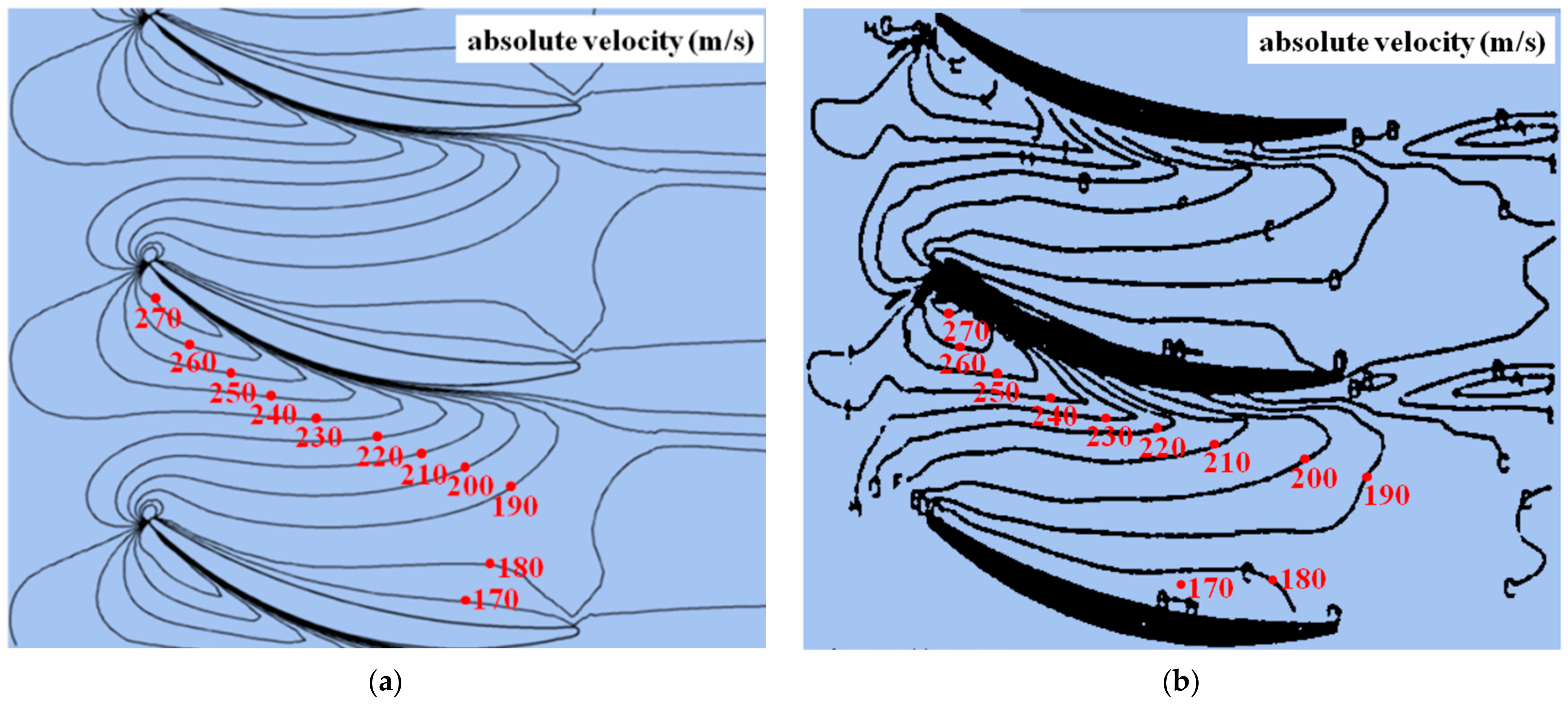
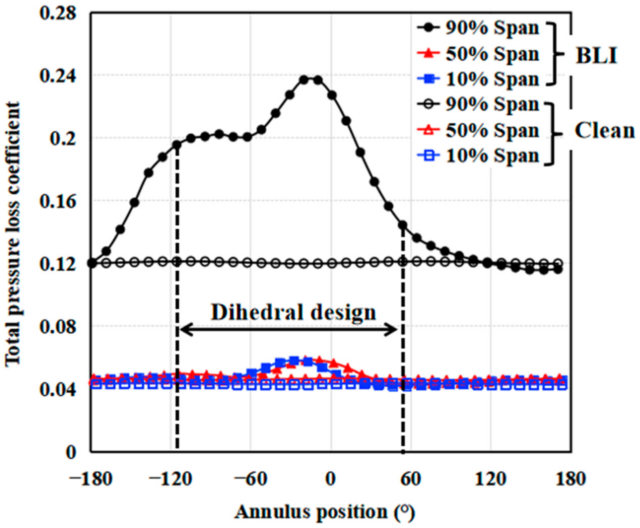
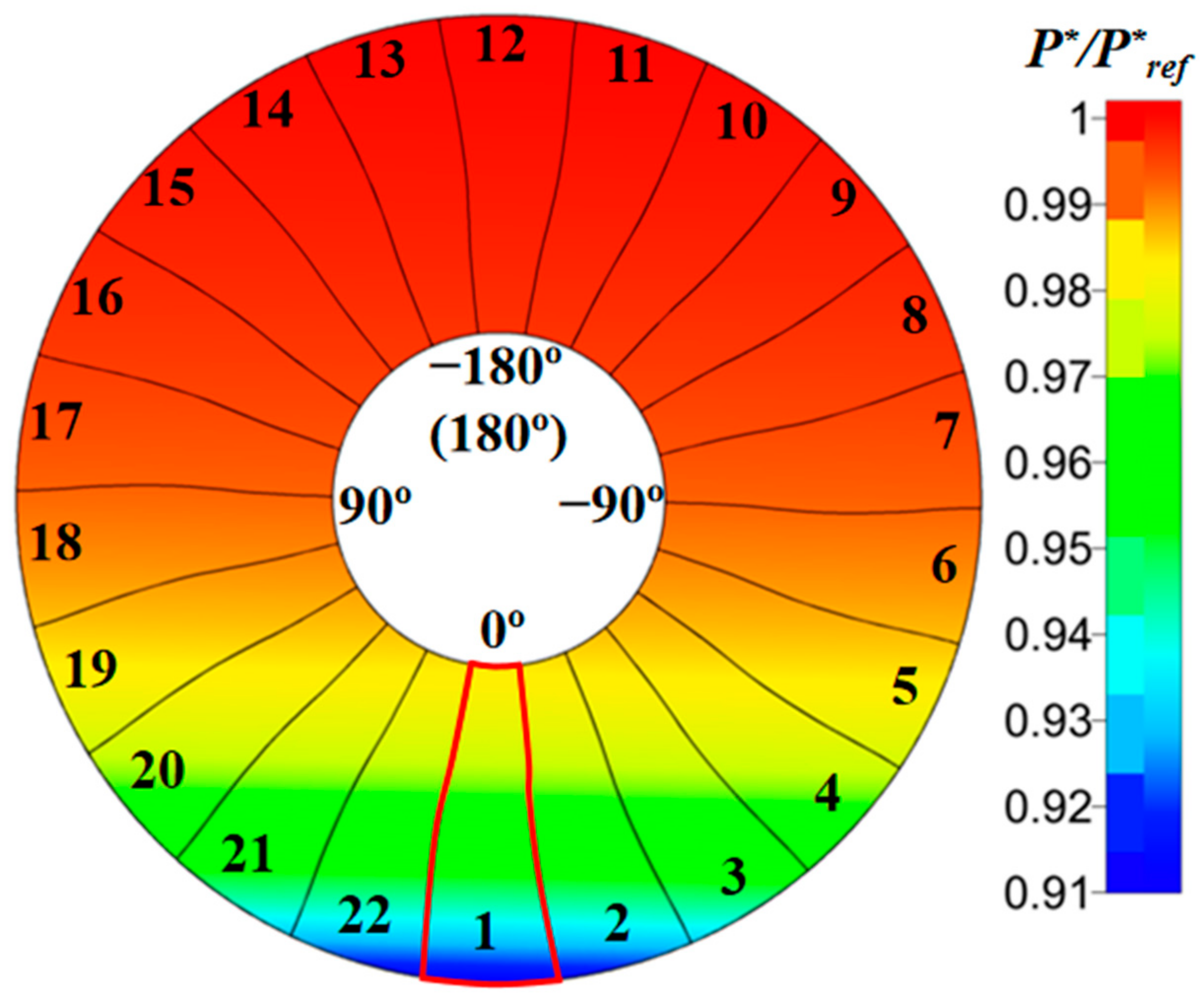
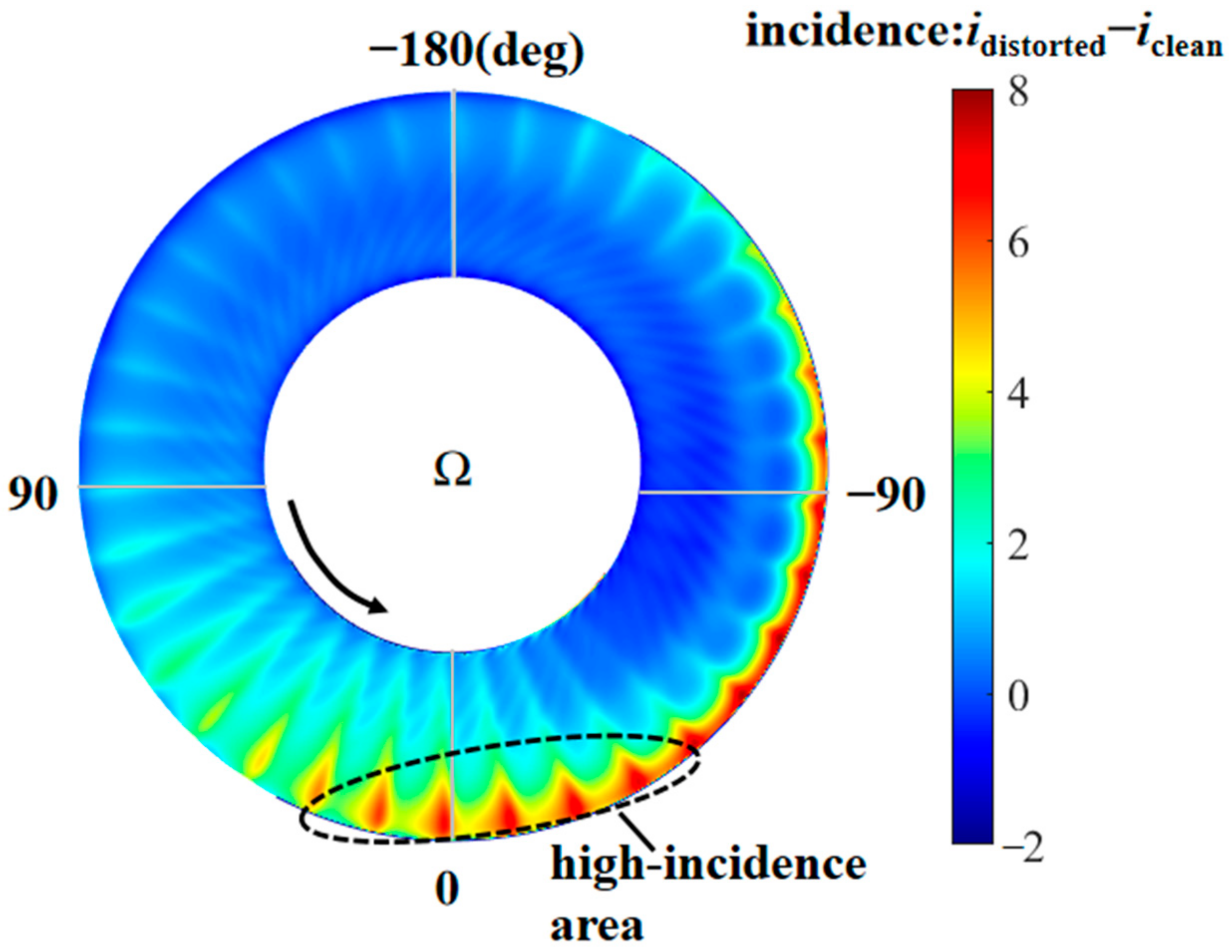
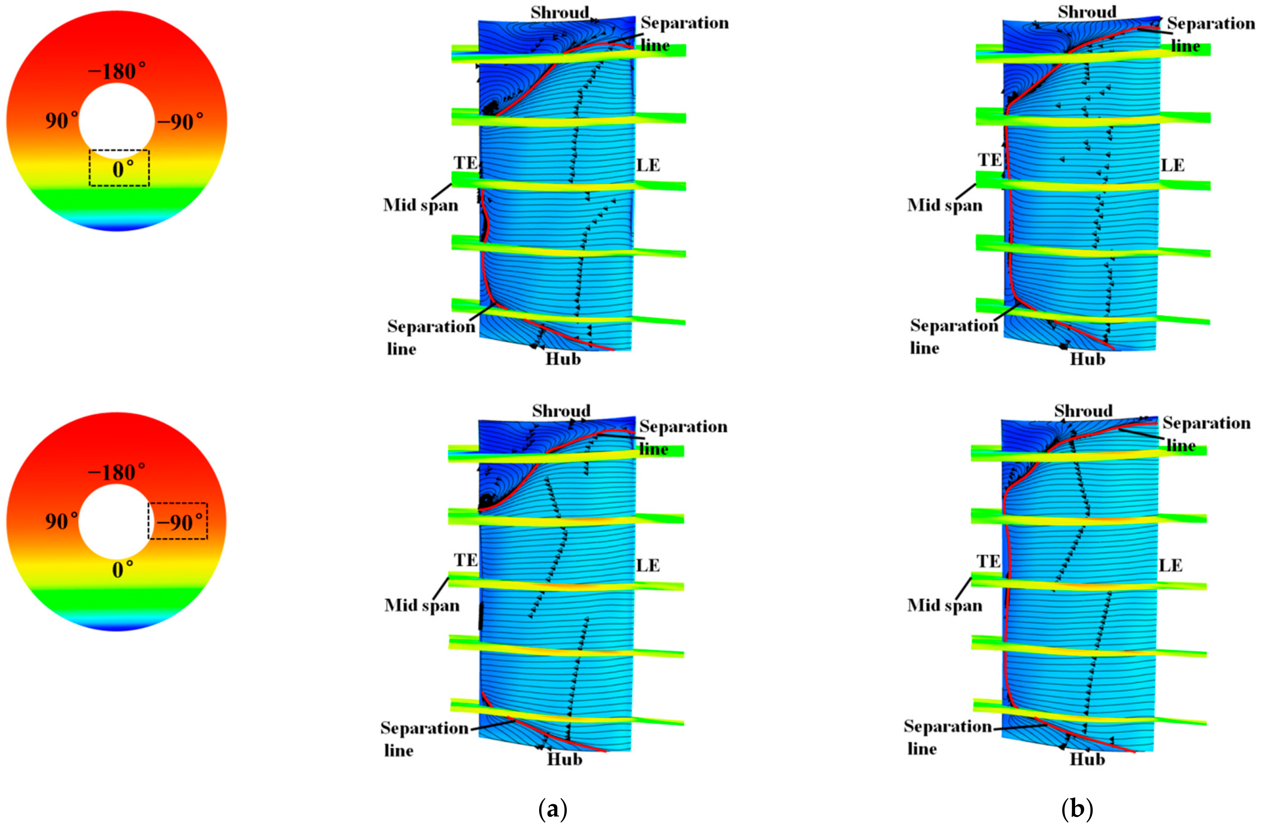
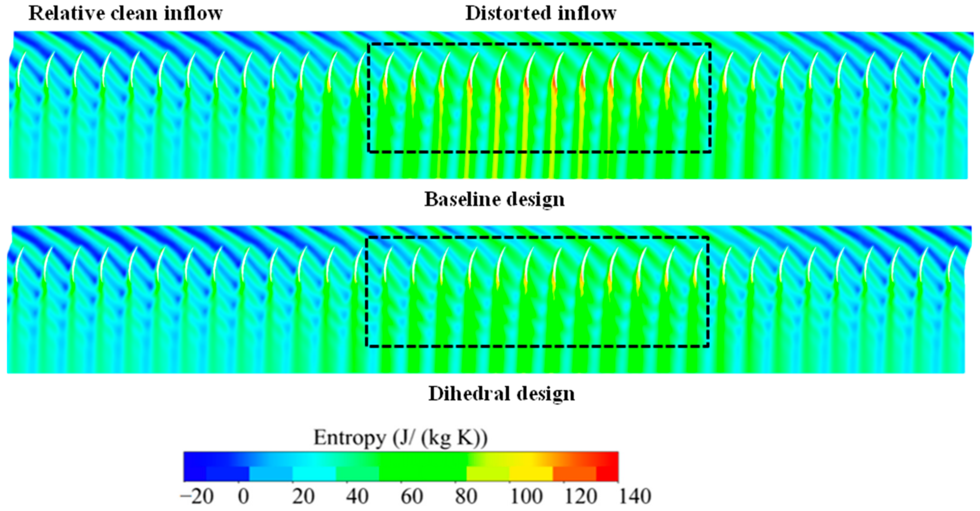
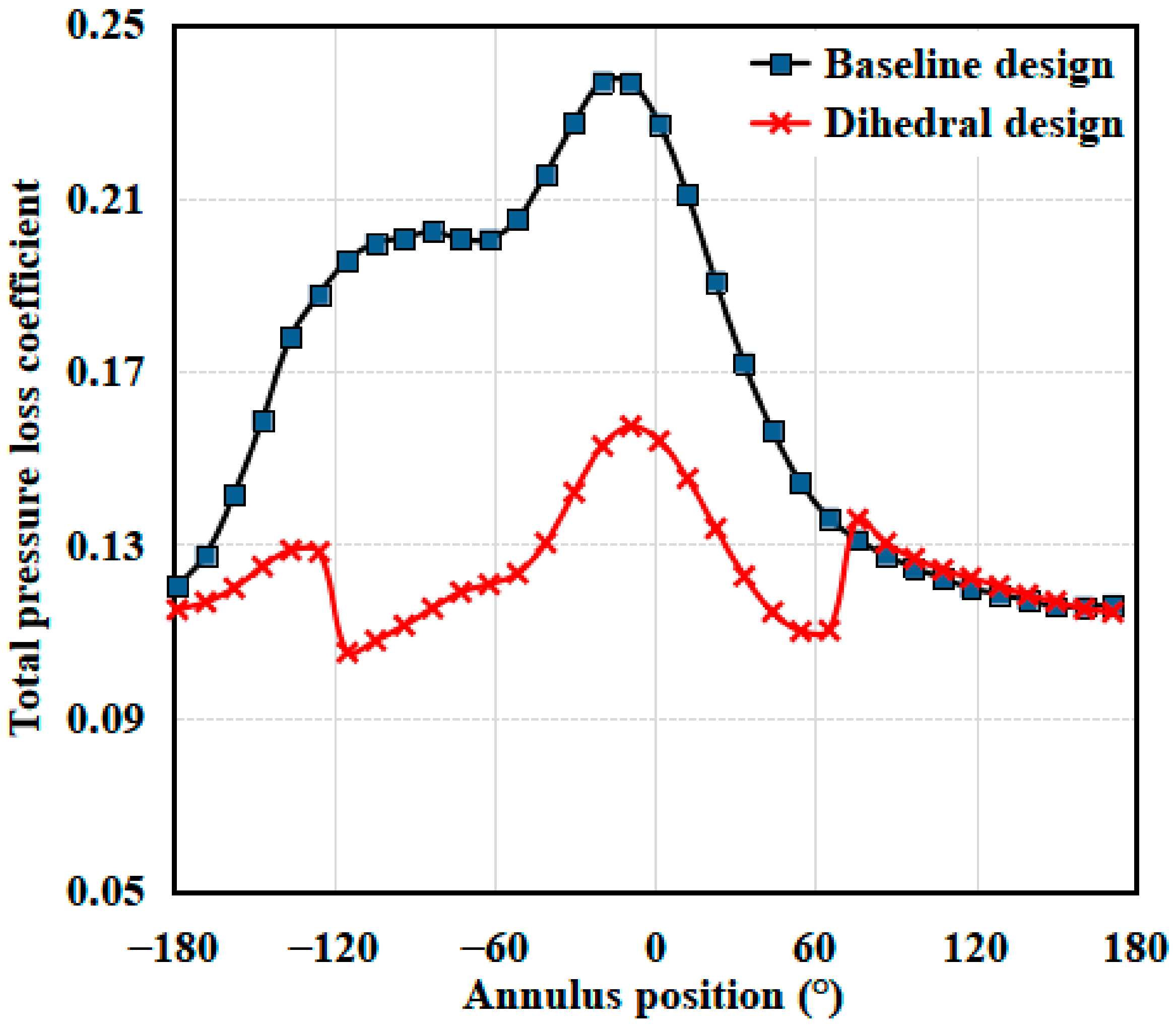
  • A circumferentially non-uniform additional loss distribution has been induced in the stator blade passage due to the BLI inflow distortion. In the radial direction, the additional loss is mainly located in the span fractions above 70% blade height. In the circumferential direction, the BLI inflow distortion has caused a large aerodynamic loss in the annulus locations covering from −120 deg to 60 deg where the rotor blade is in the process of moving from the distorted region to the undistorted region.
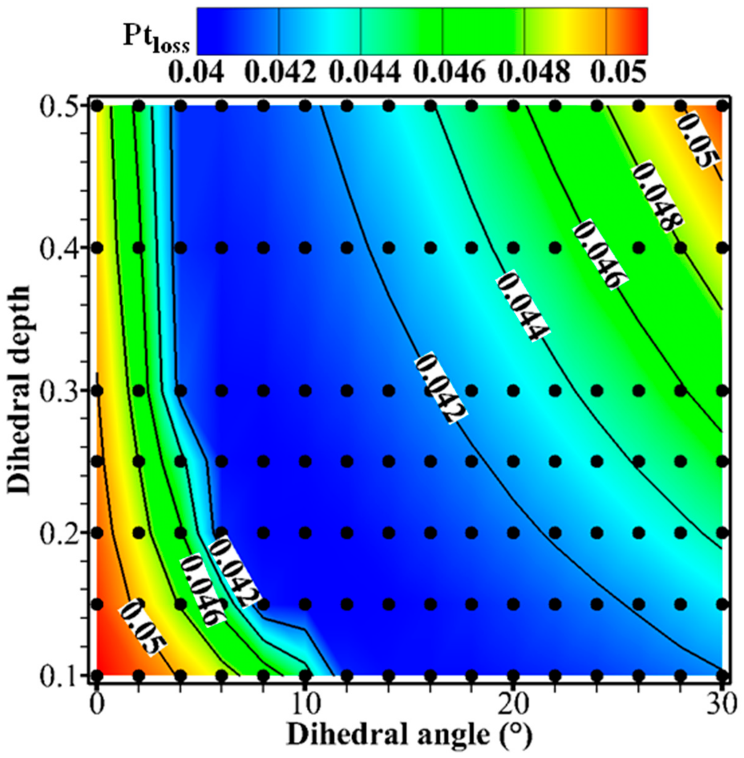
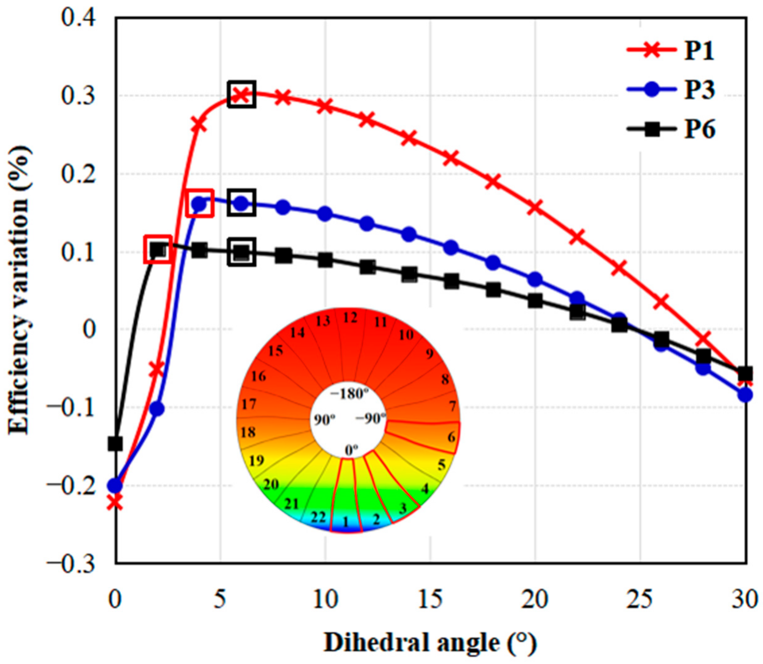
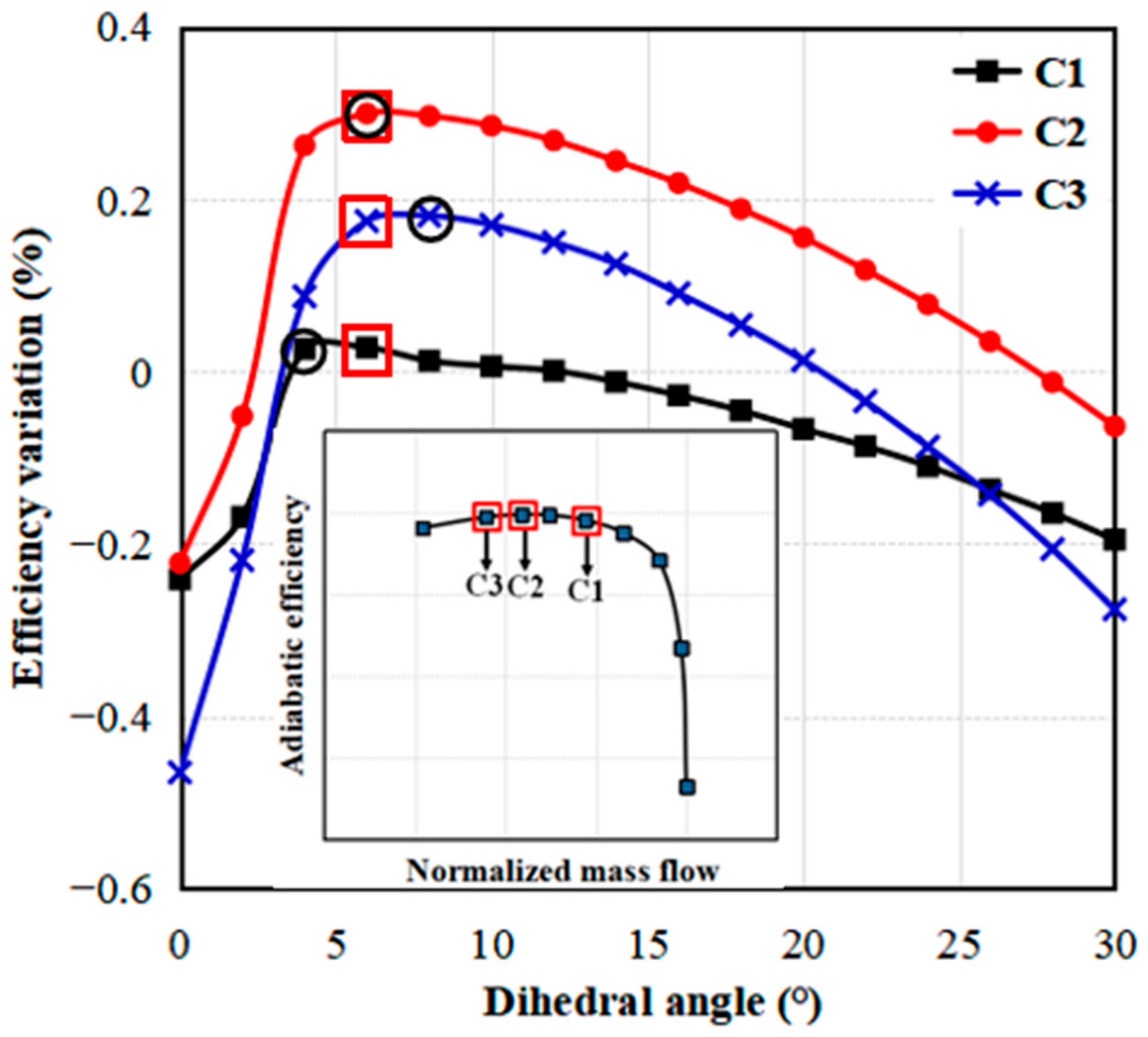
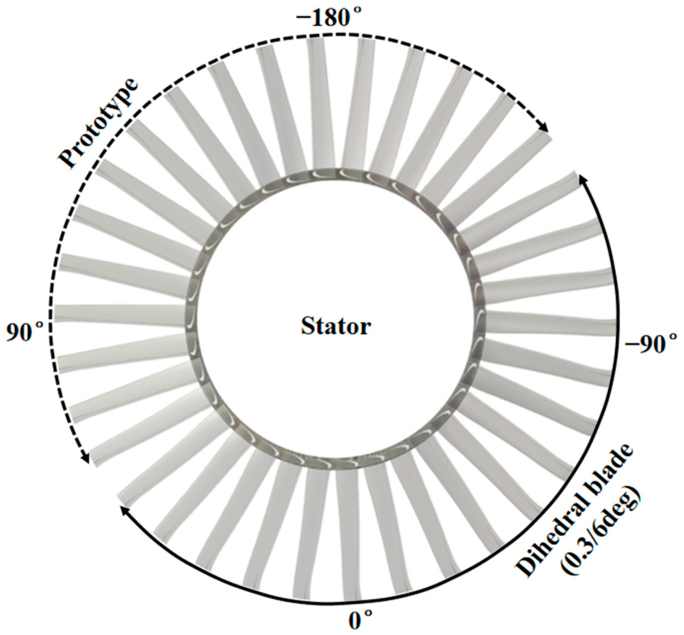
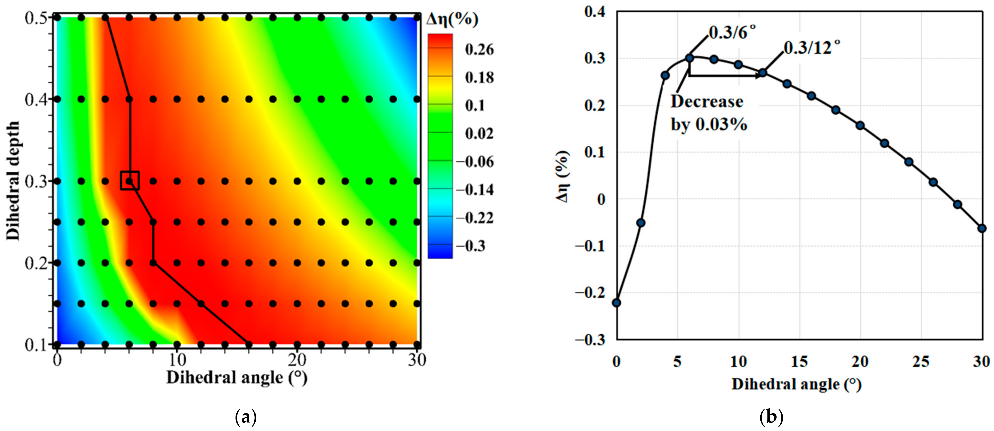
  • The full-annulus BLI fan was discretized into different portions along the annulus according to the rotor blade number, and the dihedral parameter (dihedral angle and depth) investigations were conducted at the portion with the largest inflow distortion through steady single-blade-passage simulations. There were three main results: (1) For the same dihedral depth, there was an optimal dihedral angle. (2) The optimal dihedral angle under each dihedral depth could achieve approximately the same adiabatic efficiency improvement. (3) The optimal dihedral design parameters for the largest inflow distortion were also applicable for other weaker inflow distortions. Based on these results, a non-uniform stator dihedral design strategy was developed. The optimal combinational dihedral design parameter (dihedral depth 0.3/dihedral angle 6 deg) was applied to the stator blades located from −120 deg to 60 deg annulus positions, while the stator blades in other annulus locations were unchanged.
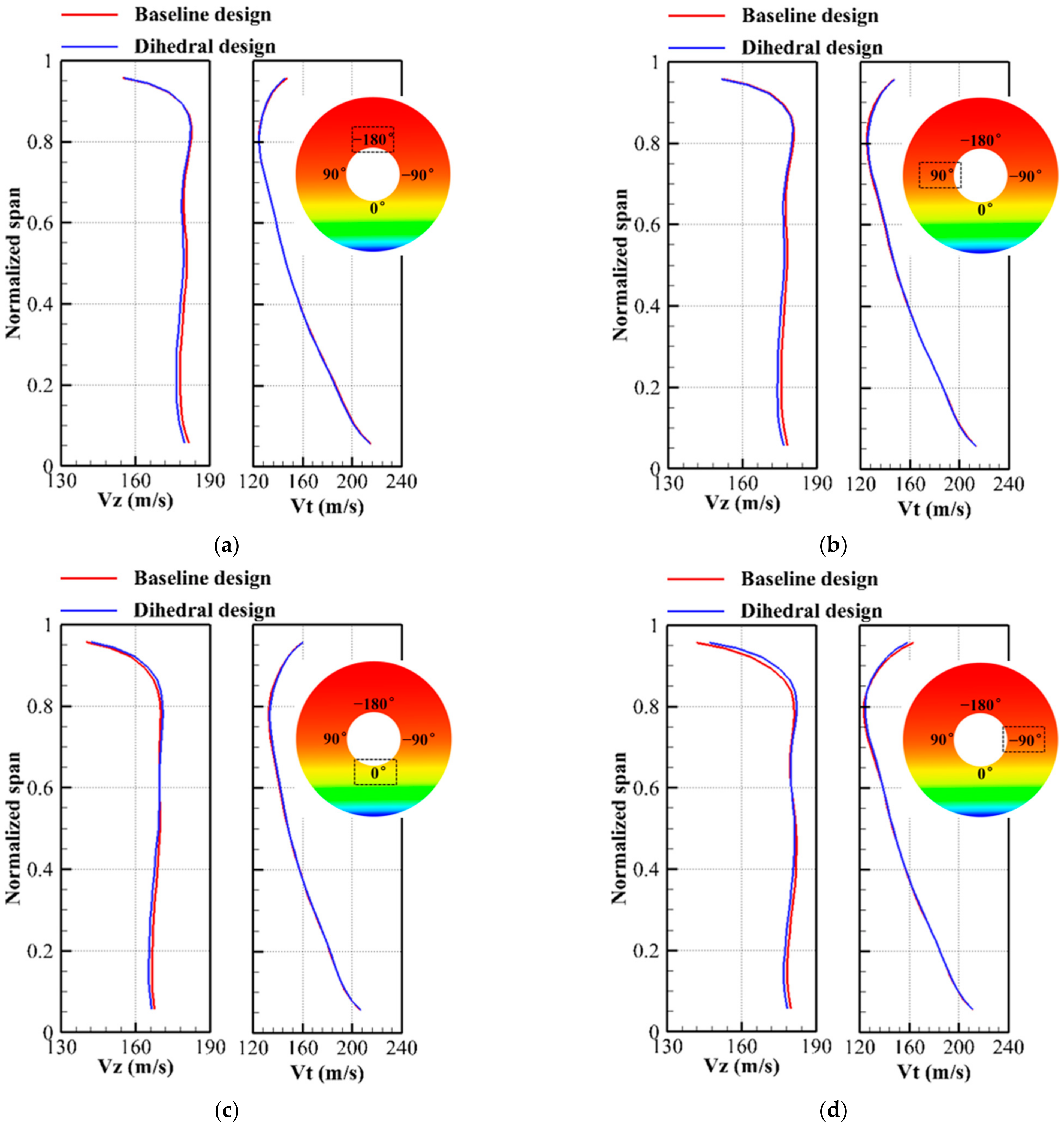
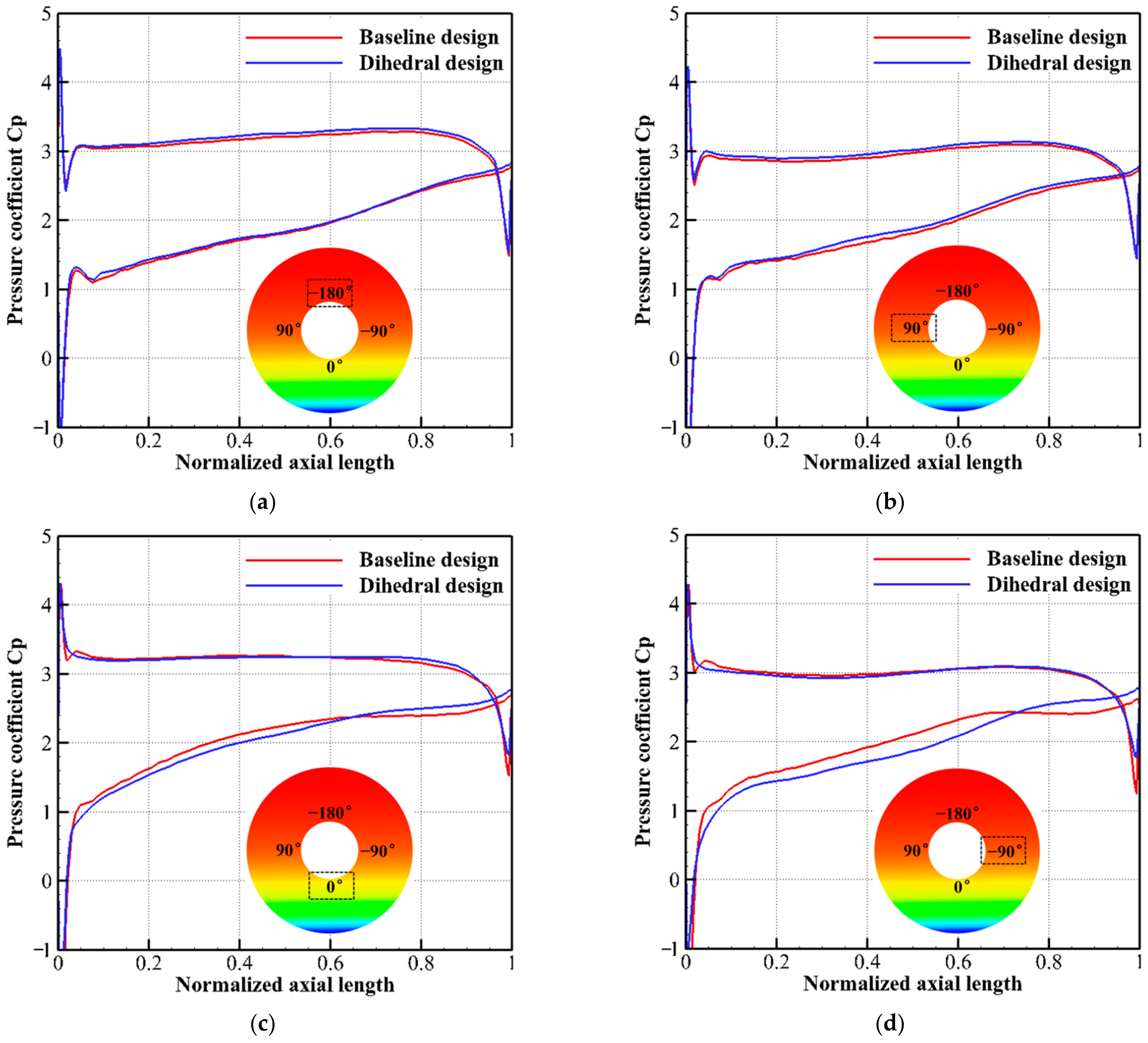
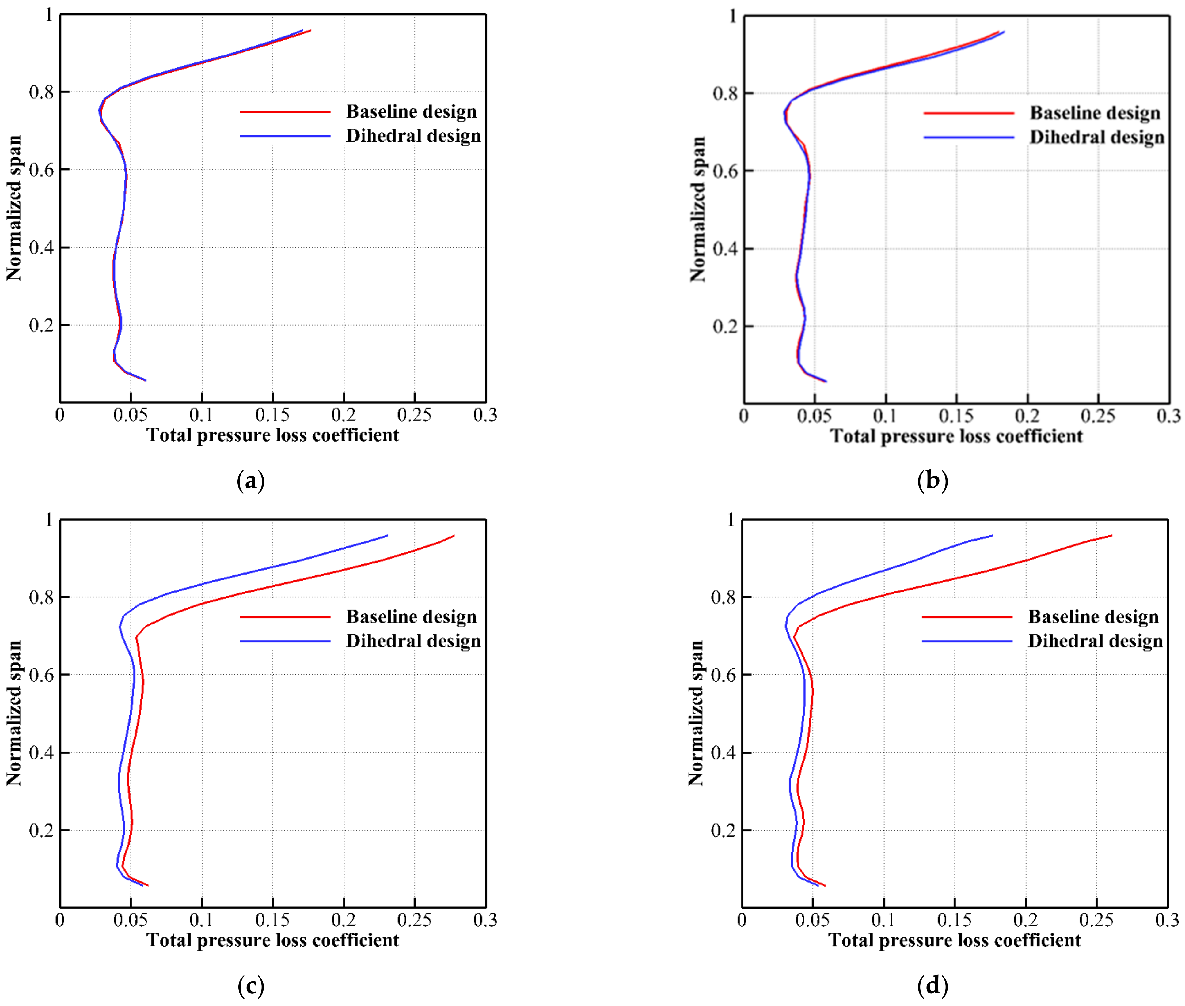
  • With the non-uniform stator dihedral design, the blade load near the trailing edge became lower than that of the baseline design in the tip region. The reduced blade load near the trailing edge had a positive effect on suppressing the flow separations. Specifically, the separation loss in the annulus locations from −120 deg to 60 deg was notably reduced and the stator aerodynamic loss decreased by about 7.7%. Meanwhile, the fan stage improved in adiabatic efficiency by about 0.48% without sacrificing the total pressure ratio.
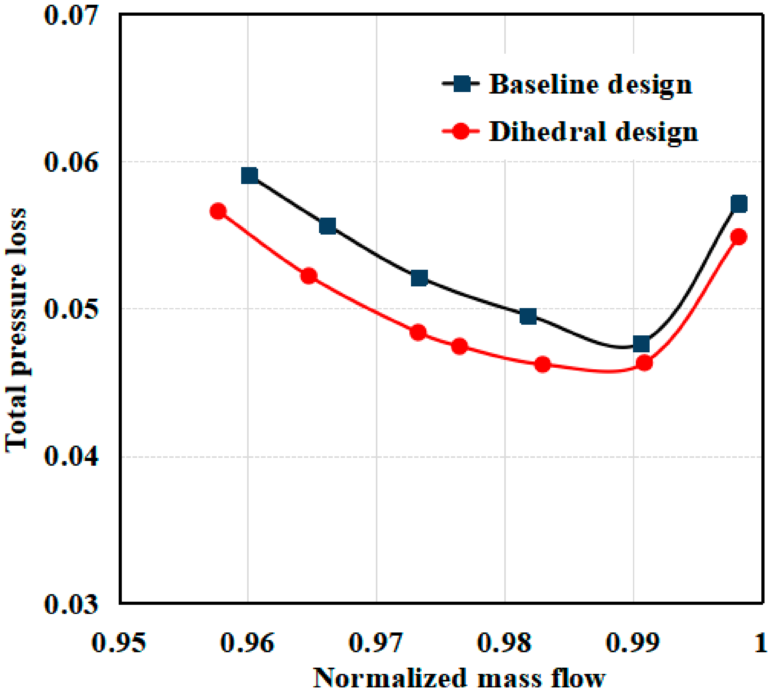
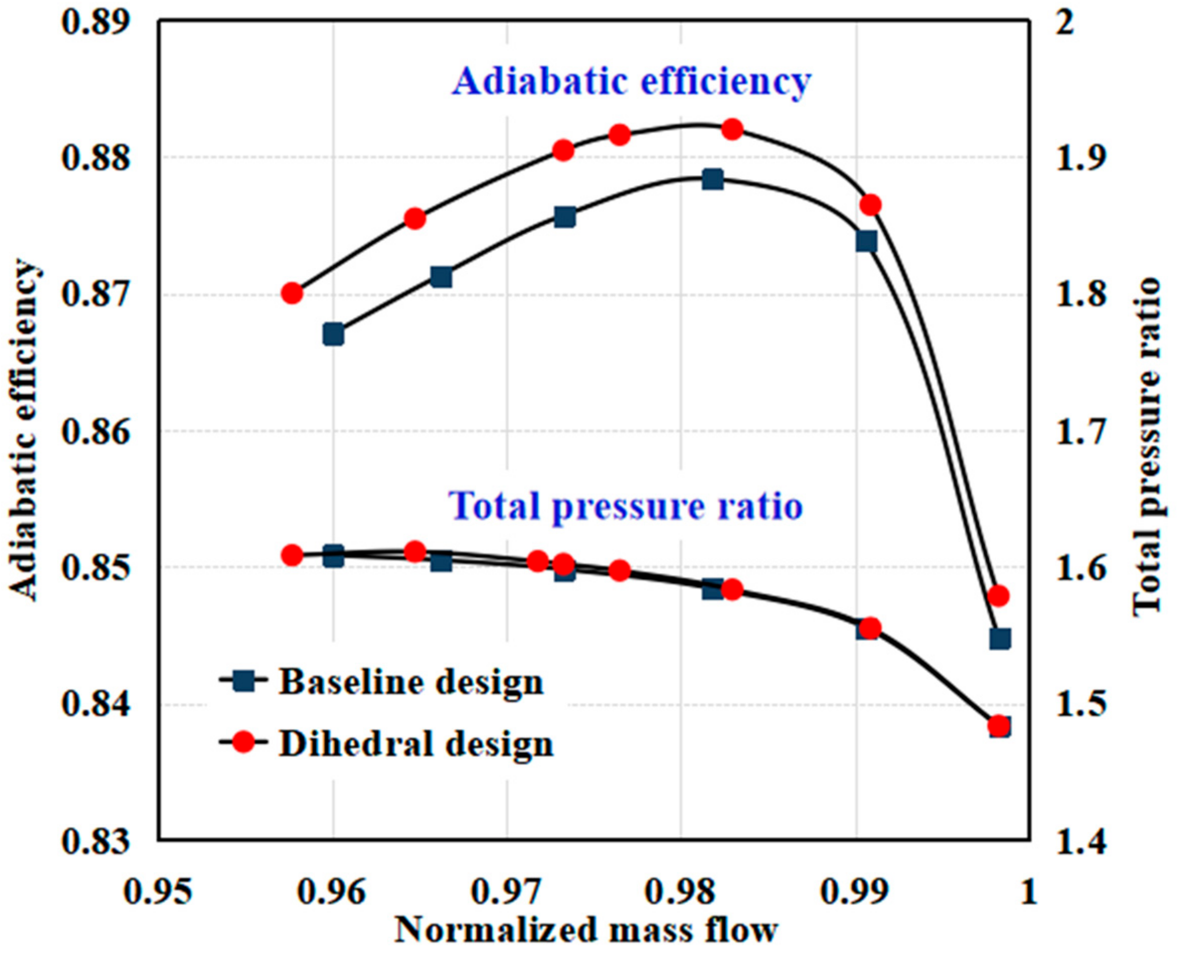
  • After the application of a non-uniform stator dihedral design, a notable performance improvement was achieved over the whole operating range. In one aspect, the aerodynamic loss of the dihedral-designed stator was lower than that of the baseline stator. Moreover, the reduction of loss was more notable as the operating mass flow decreased. In another aspect, over the whole operating range, the redesigned BLI fan showed higher adiabatic efficiency than the baseline fan while the total pressure ratio was maintained. The results suggest that the non-uniform stator dihedral design is capable of reducing the separation loss in the stator and enhancing the aerodynamic performances of the BLI fan.

Author Contributions

Conceptualization, H.L. and T.P.; methodology, H.L.; software, K.S.; validation, K.S.; formal analysis, K.S. and H.L.; investigation, K.S.; resources, H.L. and T.P.; data curation, K.S.; writing—original draft preparation, K.S., H.L. and Z.L.; writing—review and editing, K.S. and H.L.; visualization, K.S.; supervision, T.P., H.L. and J.Z.; project administration, H.L. and T.P.; funding acquisition, H.L. and T.P. All authors have read and agreed to the published version of the manuscript.

Funding

This research was funded by [National Natural Science Foundation of China] grant number [51906005 and 51976005], [Advanced Jet Propulsion Creativity Center] grant number [HKCX2020-02-013], [Fundamental Research Fund from Beihang University] grant number [YWF-22-L-1209], and [National Science and Technology Major Project] grant number [2017-II-0005-0018].

Institutional Review Board Statement

Not applicable.

Informed Consent Statement

Not applicable.

Data Availability Statement

Not applicable.

Conflicts of Interest

The authors declare no conflict of interest.

References

  1. Hileman, J.I.; Spakovszky, Z.S.; Drela, M. Airframe Design for Silent Aircraft. In Proceedings of the 45th AIAA Aerospace Sciences Meeting and Exhibit, Reno, NV, USA, 8–11 January 2007. [Google Scholar]
  2. Felder, J.; Kim, H.; Brown, G. Turboelectric Distributed Propulsion Engine Cycle Analysis for Hybrid-Wing-Body Aircraft. In Proceedings of the 47th AIAA Aerospace Sciences Meeting including the New Horizons Forum and Aerospace Exposition, Orlando, FL, USA, 5–8 January 2009. [Google Scholar]
  3. Ko, A.; Leifsson, L.T.; Mason, W.H.; Schetz, J.A.; Grossman, B. MDO of a Blended-Wing-Body Transport Aircraft with Distributed Propulsion. In Proceedings of the AIAA’s 3rd Annual Aviation Technology, Integration, and Operations (ATIO) Tech, Denver, CO, USA, 17–19 November 2003. [Google Scholar]
  4. Kim, H.; Liou, M.S. Flow Simulation of N2B Hybrid Wing Body Configuration. In Proceedings of the 50th AIAA Aerospace Sciences Meeting including the New Horizons Forum and Aerospace Exposition, Nashville, TN, USA, 9–12 January 2012. [Google Scholar]
  5. Felder, J.L.; Brown, G.V.; Kim, H.D.; Chu, J. Turboelectric Distributed Propulsion in a Hybrid Wing Body Aircraft. In Proceedings of the 20th International Society for Airbreathing Engines, Gothenburg, Sweden, 12–16 September 2011. [Google Scholar]
  6. Plas, A.P.; Sargeant, M.A.; Madani, V.; Crichton, D.; Greitzer, E.M.; Hynes, T.P.; Hall, C.A. Performance of a Boundary Layer Ingesting (BLI) Propulsion System. In Proceedings of the 45th AIAA Aerospace Sciences Meeting and Exhibit, Reno, NV, USA, 8–11 January 2007. [Google Scholar]
  7. Hall, C.A.; Schwartz, E.; Hileman, J.I. Assessment of Technologies for the Silent Aircraft Initiative. AIAA J. Propuls. Power 2009, 25, 1153–1162. [Google Scholar] [CrossRef] [Green Version]
  8. Kirner, R.; Raffaelli, L.; Rolt, A.; Laskaridis, P.; Doulgeris, G.; Singh, R. An Assessment of Distributed Propulsion: Part B-Advanced Propulsion System Architectures for Blended Wing Body Aircraft Configurations. Aerosp. Sci. Technol. 2006, 50, 212–219. [Google Scholar] [CrossRef]
  9. Uranga, A.; Drela, M.; Greitzer, E.M.; Titchener, N.A.; Lieu, M.K.; Siu, N.M.; Huang, A.C.; Gatlin, G.M.; Hannon, J.A. Preliminary Experimental Assessment of the Boundary Layer Ingestion Benefit for the D8 Aircraft. In Proceedings of the 52nd Aerospace Sciences Meeting, National Harbor, MD, USA, 13–17 January 2014. [Google Scholar]
  10. Uranga, A.; Drela, M.; Greitzer, E.M.; Hall, D.K.; Titchener, N.A.; Lieu, M.K.; Siu, N.M.; Casses, C.; Huang, A.C.; Gatlin, G.M.; et al. Boundary Layer Ingestion Benefit of the D8 Transport Aircraft. AIAA J. 2017, 55, 3693–3708. [Google Scholar] [CrossRef] [Green Version]
  11. Kim, H.; Liou, M.S. Flow Simulation and Optimal Shape Design of N3-X Hybrid Wing Body Configuration Using a Body Force Method. Aerosp. Sci. Technol. 2017, 71, 661–674. [Google Scholar] [CrossRef]
  12. Florea, R.V.; Matalanis, C.; Hardin, L.W.; Stucky, M.; Shabbir, A. Parametric Analysis and Design for Embedded Engine Inlets. AIAA J. Propuls. Power 2015, 31, 843–850. [Google Scholar] [CrossRef]
  13. Mennicken, M.; Schoenweitz, D.; Schnoes, M.; Schnell, R. Conceptual Fan Design for Boundary Layer Ingestion. In Proceedings of the ASME Turbo Expo: Turbomachinery Technical Conference and Exposition, Phoenix, AZ, USA, 17–21 June 2019. [Google Scholar]
  14. Cousins, W.T.; Voytovych, D.; Tillman, G. Design of a Distortion-Tolerant Fan for a Boundary-Layer Ingesting Embedded Engine Application. In Proceedings of the 53rd AIAA/SAE/ASEE Joint Propulsion Conference, Atlanta, GA, USA, 10–12 July 2017. [Google Scholar]
  15. Giuliani, J.; Chen, J.P. Numerical Simulation of Boundary Layer Ingesting (BLI) Inlet/Fan Interaction. In Proceedings of the 50th AIAA/ASME/SAE/ASEE Joint Propulsion Conference, Cleveland, OH, USA, 28–30 July 2014. [Google Scholar]
  16. Florea, R.V.; Voytovych, D.; Tillman, G.; Stucky, M.; Shabbir, A.; Sharma, O.; Arend, D.J. Aerodynamic Analysis of a Boundary-Layer-Ingesting Distortion-Tolerant Fan. In Proceedings of the ASME Turbo Expo: Turbine Technical Conference and Exposition, San Antonio, TX, USA, 3–7 June 2013. [Google Scholar]
  17. Li, D.; Lu, H.; Yang, Z.; Pan, T.; Du, H.; Li, Q. Optimization of a Transonic Axial-Flow Compressor under Inlet Total Pressure Distortion to Enhance Aerodynamic Performance. Eng. Appl. Comput. Fluid Mech. 2020, 14, 1002–1020. [Google Scholar] [CrossRef]
  18. Gunn, E.J.; Hall, C.A. Aerodynamics of Boundary Layer Ingesting Fans. In Proceedings of the ASME Turbo Expo: Turbine Technical Conference and Exposition, Düsseldorf, Germany, 16–20 June 2014. [Google Scholar]
  19. Gunn, E.J.; Hall, C.A. Non-Axisymmetric Stator Design for Boundary Layer Ingesting Fans. ASME J. Turbomach. 2019, 141, 071010. [Google Scholar] [CrossRef] [Green Version]
  20. Shang, E.; Wang, Z.Q.; Su, J.X. The Experimental Investigations on the Compressor Cascades with Leaned and Curved Blades. In Proceedings of the ASME Turbo Expo: Power for Land, Sea, and Air, Cincinnati, OH, USA, 24–27 May 1993. [Google Scholar]
  21. Fischer, A.; Riess, W.; Seume, J.R. Performance of Strongly Bowed Stators in a 4-Stage High Speed Compressor. In Proceedings of the ASME Turbo Expo: Power for Land, Sea, and Air, Atlanta, GA, USA, 16–19 June 2003. [Google Scholar]
  22. Wellborn, S.R.; Delaney, R.A. Redesign of a 12-Stage Axial-Flow Compressor Using Multistage CFD. In Proceedings of the ASME Turbo Expo: Power for Land, Sea, and Air, New Orleans, LA, USA, 4–7 June 2001. [Google Scholar]
  23. Wang, Z.; Su, J.; Zhong, J. The Effect of the Distribution in a Three-Dimensional Flow Field of a Cascade on the Type of Curved Blade. In Proceedings of the ASME Turbo Expo: Power for Land, Sea, and Air, The Hague, The Netherlands, 13–16 June 1994. [Google Scholar]
  24. Weingold, H.D.; Neubert, R.J.; Behlke, R.F.; Potter, G.E. Bowed Stator: An Example of CFD Applied to Improve Multistage Compressor Efficiency. ASME J. Turbomach. 1997, 119, 161–168. [Google Scholar] [CrossRef]
  25. Breugelmans, F.A.E. Influence of Incidence Angle on the Secondary Flow in Compressor Cascade with Different Dihedral Distribution. In Proceedings of the 7th International Symposium on Air-breathing Engines, Beijing, China, 2–6 September 1985. [Google Scholar]
  26. Takahashi, Y.; Hamatake, H.; Katoh, Y.; Toda, M.; Kashiwabara, Y. Experimental and Numerical Investigations of Endwall Flow in a Bowed Compressor Cascade. In Proceedings of the 41st AIAA/ASME/SAE/ASEE Joint Propulsion Conference & Exhibit, Tucson, AZ, USA, 10–13 July 2005. [Google Scholar]
  27. Gümmer, V.; Wenger, U.; Kau, H.P. Using Sweep and Dihedral to Control Three Dimensional Flow in Transonic Stators of Axial Compressor. ASME J. Turbomach. 2001, 123, 40–48. [Google Scholar] [CrossRef]
  28. Gallimore, S.J.; Bolger, J.J.; Compsty, N.A.; Taylor, M.J.; Wright, P.I.; Place, J.M. The Use of Sweep and Dihedral in Multistage Axial Flow Compressor Blading: Part I-University Research and Methods Development. ASME J. Turbomach. 2002, 124, 521–532. [Google Scholar] [CrossRef]
  29. Gallimore, S.J.; Bolger, J.J.; Compsty, N.A.; Taylor, M.J.; Wright, P.I.; Place, J.M. The Use of Sweep and Dihedral in Multistage Axial Flow Compressor Blading: Part II-Low and High Speed Designs and Test Verification. ASME J. Turbomach. 2002, 124, 533–541. [Google Scholar] [CrossRef]
  30. Hathaway, M.D. Unsteady Flows in a Single-Stage Transonic Axial-Flow Fan Stator Row. Ph.D. Thesis, Iowa State University, Ames, IA, USA, 1986. [Google Scholar]
  31. Spalart, P.; Allmaras, S.R. A One Equation Turbulence Model for Aerodynamic Flows. In Proceedings of the 30th Aerospace Sciences Meeting and Exhibit, Reno, NV, USA, 6–9 January 1992. [Google Scholar]
  32. Mohsen, M.; Owis, F.M.; Hashim, A.A. The Impact of Tandem Rotor Blades on the Performance of Transonic Axial Compressors. Aerosp. Sci. Technol. 2017, 67, 237–248. [Google Scholar] [CrossRef]
  33. Sun, S.; Chen, S.; Liu, W.; Gong, Y.; Wang, S. Effect of Axisymmetric Endwall Contouring on the High-Load Low-Reaction Transonic Compressor Rotor with a Substantial Meridian Contraction. Aerosp. Sci. Technol. 2018, 81, 78–87. [Google Scholar] [CrossRef]
Figure 1. Meridional geometry of the investigated fan stage.
Energies 15 05791 g001
Figure 2. Computational domain and inlet total pressure distribution.
Energies 15 05791 g002
Figure 3. Computational grid in the transonic fan stage. (a) Rotor mesh; (b) Stator mesh.
Energies 15 05791 g003
Figure 4. The results of the grid independence study.
Energies 15 05791 g004
Figure 5. Comparison of performance maps between CFD results and experimental data.
Energies 15 05791 g005
Figure 6. Absolute velocity contours on the blade-to-blade plane in the stator passage at the design point at 50% span. (a) CFD results; (b) Experimental data.
Energies 15 05791 g006
Figure 7. Distribution of incidence angle at the stator inlet.
Energies 15 05791 g007
Figure 8. Comparisons of total pressure loss distributions at 10%, 50%, and 90% span under BLI inlet distortion and clean inflow conditions.
Energies 15 05791 g008
Figure 9. Parameterization of a blade airfoil section. (a) Blade airfoil; (b) Camber line; (c) Suction surface.
Energies 15 05791 g009
Figure 10. Schematic graph of tangential stacking line for the dihedral blade.
Energies 15 05791 g010
Figure 11. Comparison of the baseline stator blade (left) and the dihedral-designed stator blade (right).
Energies 15 05791 g011
Figure 12. Scheme of dividing the full-annulus BLI fan.
Energies 15 05791 g012
Figure 13. Numerical simulation scheme of stator blade dihedral design.
Energies 15 05791 g013
Figure 14. Effects of dihedral depth and dihedral angle on stator loss.
Energies 15 05791 g014
Figure 15. The effects of dihedral angle and dihedral depth on fan stage efficiency. (a) Dihedral angle and depth on fan efficiency; (b) Dihedral angle on fan efficiency with dihedral depth 0.3.
Energies 15 05791 g015
Figure 16. The efficiency variation with the dihedral angle at different inflow portions (dihedral depth = 0.3).
Energies 15 05791 g016
Figure 17. The efficiency variation with the dihedral angle at different mass flow operating conditions (dihedral depth = 0.3).
Energies 15 05791 g017
Figure 18. Scheme of non-uniform stator dihedral design.
Energies 15 05791 g018
Figure 19. Radial distributions of pitch-averaged axial and tangential velocities at the inlet of baseline and dihedral stators for different annulus positions. (a) −180 deg; (b) 90 deg; (c) 0 deg; (d) −90 deg.
Energies 15 05791 g019
Figure 20. Static pressure distributions along the chordwise direction at different annulus positions at a 90% span for the baseline stator and dihedral stator. (a) −180 deg; (b) 90 deg; (c) 0 deg; (d) −90 deg.
Energies 15 05791 g020
Figure 21. Comparisons of flow separations in stator blade passages between the baseline design and dihedral design at different annulus positions. (a) Baseline design, (b) Dihedral design.
Energies 15 05791 g021aEnergies 15 05791 g021b
Figure 22. Comparisons of radial distributions of stator loss between the baseline design and the dihedral design at different annulus positions. (a) −180 deg; (b) 90 deg; (c) 0 deg; (d) −90 deg.
Energies 15 05791 g022
Figure 23. Comparison of entropy contours on the blade-to-blade surface at 90% span in stator blade passage between the baseline design and the dihedral design.
Energies 15 05791 g023
Figure 24. Circumferential distributions of stator loss at 90% span for the baseline and dihedral designs.
Energies 15 05791 g024
Figure 25. Comparison of the stator loss between the baseline design and the non-uniform dihedral design over the whole operating range.
Energies 15 05791 g025
Figure 26. Comparisons of overall performance maps between the baseline design and the non-uniform stator dihedral design.
Energies 15 05791 g026
Table 1. Stage 67 design parameters.
ParametersValues
Rotor aspect ratio1.56
Rotor solidity at tip and hub1.29/3.114
Rotor tip speed (m/s)429
Rotor hub-to-tip ratio at inlet0.375
Stator solidity at tip and hub1.271/2.485
Stator hub-to-tip ratio at inlet0.5
Table 2. Comparisons of aerodynamic performances between the baseline design and non-uniform stator dihedral design under BLI inflow distortion conditions.
Stage EfficiencyStator Loss
Baseline design87.57%0.052
Dihedral design88.05%0.048
Relative change0.48%7.7%
Publisher’s Note: MDPI stays neutral with regard to jurisdictional claims in published maps and institutional affiliations.

