Article

Double Impedance-Substitution Control of DFIG Based Wind Energy Conversion System

1
School of Electrical and Electronic Engineering, Harbin University of Science and Technology, Harbin 150080, China
2
School of Electrical Engineering and Automation, Harbin Institute of Technology, Harbin 150001, China
3
Harbin Electrical Machinery Company Limited, Harbin 150040, China
*
Author to whom correspondence should be addressed.
Energies 2022, 15(15), 5739; https://doi.org/10.3390/en15155739
Submission received: 11 July 2022 / Revised: 1 August 2022 / Accepted: 2 August 2022 / Published: 8 August 2022
(This article belongs to the Section F3: Power Electronics)

Abstract

:
In a doubly-fed induction generator (DFIG)-based wind energy conversion system (WECS), when the grid voltage sags severely, the rotor side converter (RSC) suffers from overvoltage and overcurrent owing to the large electromotive force (EMF). To ensure that the converter operates within a safe range when grid faults occur, this paper proposes a double impedance-substitution control (DISC) strategy to improve the system’s low-voltage ride through (LVRT) capability. When the grid voltage sag is detected, the grid side converter (GSC) and RSC are connected in parallel to the rotor circuit by changing the topology of the system. In the new topology, GSC and RSC are equivalent to inductive impedance by controlling, which can not only suppress the overvoltage and overcurrent at the rotor side, but also effectively reduce the torque ripple. Additionally, the DISC strategy can provide reactive power support to the grid during LVRT. Finally, the simulation results show that the DISC strategy can maintain the current flowing through the RSC within ±1 p.u., and compared with the existing control strategy, the effectiveness of the proposed method was further demonstrated.

1. Introduction

In the past decades, with the increasingly prominent energy and environmental problems, the wind power industry and technology have made significant developments, and the widespread installation in the grid has had an increasing impact on the power system [1]. Many countries have formulated standards for wind power grid connections and have clearly defined that the WECS should be provided with the capability of low-voltage ride through (LVRT). For example, Figure 1 shows China’s requirements for wind-farm LVRT. When the grid-connected voltage drop is above 0.2 p.u., the wind turbine can still operate continuously as well as provide a reactive current according to the standard in Figure 1b.
Among all types of wind turbines, the doubly-fed induction generator (DFIG) occupies a large market share of the WECS owing to its low cost, small converter capacity, and flexible control [2]. However, the DFIG is very vulnerable to non-ideal grid characteristics as a result of their direct connection to the grid at the stator side. If a severe fault occurs, the DFIG induces a large rotor electromotive force (EMF). If no effective protective measures are taken, the current and voltage of rotor side converter (RSC) and DC-bus will exceed its threshold, resulting in unit loss of control or device damage [3,4].
Many methods have been investigated for the LVRT issue. These methods are mainly divided into two categories: (1) those based on additional hardware devices; and (2) those based on design-specific control strategies. The most effective additional device to deal with grid voltage sag is the dynamic voltage restorer (DVR) device [5], which can inject compensation voltage into the grid through a series transformer to eliminate the impact of voltage sag, resolving the fault crisis fundamentally. However, the DVR usually requires a converter of large size capacity as well as energy storage to quickly inject sufficient power to boost the grid voltage, which is economically unacceptable. Thanks to the advantages of simple operation and low cost, the crowbar is a widely used LVRT auxiliary device [6]. However, when the crowbar receives the trigger pulse, the RSC must block the pulse. This loses system controllability, nor can it inject reactive current for the grid. In this scenario, the DFIG is equivalent to a squirrel-cage asynchronous motor, which must uptake reactive power from the grid [7]. References [8,9,10] realize LVRT by configuring a fault current limiter (FCL), when the stator current exceeds the set value, the adaptive FCL impedance increases instantaneously, limiting the grid fault current by inducing a large voltage drop. However, during fault current limiting, the high impedance leads to increased energy losses and a poor current limiting effect on the RSC. In addition, stator-side series dynamic resistance [11] and RSC in parallel with an additional rectifier and energy storage device is effective [12], but it requires additional cost and increases the control complexity. Reference [13] changed the three-winding transformer in the traditional DFIG-based WECS into two single-winding transformers, changing the traditional topology, so that GSC can adjust the stator voltage of DFIG. But the author’s default traditional structure is based on systems equipped with crowbar and battery energy storage devices. It is hard to use a conventional solution for the DFIG to cope with grid-voltage sags.
In addition to the utilization of various auxiliary devices, there are methods to design specific control strategies to meet the grid code requirements. Reference [14] considered the transient process of the grid voltage sag and proposed an improved calculation method for the feedforward terms. Reference [15] used a fuzzy controller, reference [16] used a hysteresis controller, and reference [17] used a sliding mode controller to replace the traditional PI controller. These methods enhanced the anti-interference performance of the current loop. However, it can only improve the control ability of the system but cannot accelerate the attenuation of the flux linkage transient component. Therefore, during a long transient process, the RSC must output a sufficient voltage to cancel the EMF. Once a severe fault occurs, the EMF is likely to exceed the maximum voltage permitted by the RSC, resulting in RSC saturation and a loss of control of the system. Simultaneously, the dynamic stator flux causes a large ripple in the electromagnetic torque and endangers the transmission system. Reference [18] set the detected stator current directly to RSC current reference value, which achieved the effect of suppressing the RSC current. Nevertheless, the RSC must output a large voltage. In [19], the concept of virtual damping flux was proposed and used in the analysis and research for a LVRT scheme. A control strategy in which the rotor current tracks the reverse stator current proportionally was proposed. However, the value range of the proportional coefficient is not sufficiently precise. In some cases, the RSC may not meet the voltage constraint, leading to saturation and affecting the regulation of current, which weakened the effect of the control strategy. To end the transient process caused by a voltage sag as soon as possible, demagnetization control technology was proposed in [20,21]. during a voltage dip, the negative and zero sequences of the stator flux are obtained by using flux linkage observation and phase sequence separation technology, and the rotor reference current required to offset them is calculated. Since the output voltage of the RSC is primarily used to offset the positive-sequence component of EMF, the voltage requirement on the rotor side is low. However, RSC is bound to withstand high current stress due to the large injection demagnetization current. In the event of a severe fault in the grid, it may even exceed 2   p . u . , which not only fails to inject reactive power support, but may also cause damage to the converter, resulting in huge losses. In [22], the demagnetization current reference was superposed with the normal rotor current reference, and the RSC and grid side converter (GSC) completed demagnetization and reactive power support at the same time. However, this method also has a problem in that the current is too large, which requires a larger converter of the current capacity. The above optimal control strategy scheme attempts to realize LVRT only by RSC, but owing to the limited capacity of RSC, these control strategies may not enable the unit to achieve LVRT under very serious grid faults.
In this paper, based on the condition of satisfying the converter voltage and current constraints, considering various control objectives such as reducing torque ripple, accelerating flux linkage attenuation, and providing reactive power support, a double impedance-substitution control (DISC) strategy is proposed. during the proposed strategy implementation, the GSC with a low utilization rate is connected in parallel with the RSC to the rotor side, and the GSC and RSC are equivalent to the inductive impedance by controlling. with a minimum of additional components (cost), the output currents of the two converters can be maintained within ± 1   p . u . regardless of the normal or fault conditions, such that the converter is always in a safe operating area.
This paper is organized as follows. A mathematical model of the DFIG is established, and the transient characteristics of the DFIG under a voltage sag are analyzed in Section 2. In Section 3, the principle of the DISC control scheme is described in detail and the selection of relevant parameters is discussed. In Section 4, a group of simulation results are compared to demonstrate the correctness and effectiveness of the proposed method. Finally, conclusions are summarized in Section 5.

2. Transient Characteristics of DFIG under Grid Voltage Sags
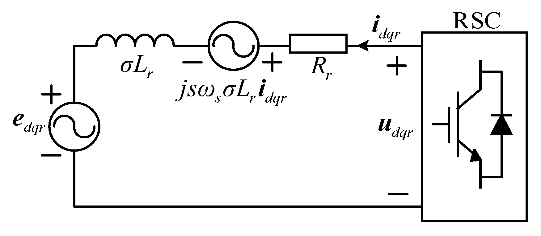
2.1. DFIG Model

In this paper, the space vector method is used to express the motor parameters. For simplicity, the stator and rotor winding currents flowing into the motor are specified as positive, and all variables on the rotor are referred to the stator according to the turn ratio. In the synchronous reference frame (dq) oriented to the stator flux linkage, the voltage and flux linkage equations are given by [23].
{ u d q s = R s i d q s + d d t ψ d q s + j ω s ψ d q s u d q r = R r i d q r + d d t ψ d q r + j ( ω s ω r ) ψ d q r
{ ψ d q s = L s i d q s + L m i d q r ψ d q r = L m i d q s + L r i d q r
where u , i , and ψ are the voltage, current, and flux-linkage vectors, respectively. R and L are the resistance and inductance, respectively. ω is the electrical angular frequency. L s = L s σ + L m and L r = L r σ + L m . L s σ and L r σ are the stator and rotor leakage inductance, respectively. L m denotes the mutual inductance. The subscripts “s” and “r” denote the stator and rotor variables, respectively.
From (1) and (2), the expression for the rotor voltage is given below:
u d q r = L m L s ( d d t + j s ω s ) ψ d q s + ( R r + σ L r d d t + j s ω s σ L r ) i d q r
In (3), σ = 1 L m 2 / ( L s L r ) denotes the leakage coefficient. σ L r is the rotor-side transient inductance and s is the slip.
According to (3), the rotor voltage consists of two components. The first term is the induced EMF e d q r related to the rate of change of the stator flux linkage, and the second term is related to the voltage drop across the rotor impedance, denoted as u R L . The equivalent circuit on the rotor side is illustrated in Figure 2.

2.2. EMF Transient Characteristics

Under normal conditions, ψ d q s is constant. The first term in (3) can be rewritten as:
e d q r = j L m L s s ω s ψ d q s = L m L s s U m
Here, U m is the stator voltage vector amplitude.
As (4) indicates, under normal conditions, the amplitude of EMF is in direct proportion to the slip s. Due to the range of slip being extensively designed between –0.3 and +0.3, the magnitude of EMF is less than 30% of U m . In case the grid sags symmetrically, the stator flux linkage cannot contain a sudden change; therefore, in addition to the steady-state component, the stator flux linkage also contains a transient component that decays with time, which can be expressed as:
ψ d q s = ( 1 h ) U m j ω s + h U m j ω s e t τ s 1 e j ω s t
where h is the depth of the grid voltage drop. τ s 1 = L s / R s is the time constant of the stator flux linkage. Under symmetrical faults, neglecting the smaller time constant 1 / τ s 1 , from (4) and (5), the EMF can be rewritten as:
e d q s = L m L s [ s ( 1 h ) U m ( 1 s ) h U m e t τ s 1 e j ω s t ]
The first and second items represent the steady-state and transient components of the EMF, respectively. According to (6), the second item of the EMF is positive correlation with the ( 1 s ) . If the grid voltage sags completely and the slip is −0.3, the initial value of EMF 1.3 U m L m / L s is the maximum value, which is 4.33 times higher than the EMF during normal operation.
According to the above analysis, when the grid has a severe fault, the EMF increases sharply, thus increasing the RSC request voltage. However, the peak voltage of RSC depends on the modulation method and DC-bus voltage, and they are engineered based on normal situations. If the RSC maintains the original control scheme during grid fault, the requested voltage of the RSC is likely to be higher than the RSC voltage threshold, which leads to overmodulation out of control. Therefore, in the design of any LVRT control strategy, the voltage constraints of the RSC should be satisfied first, followed by the current constraints of the RSC and the suppression of the DC-bus overvoltage. Thus, the DFIG-based WECS can operate safely during LVRT.

3. The Principle of DISC

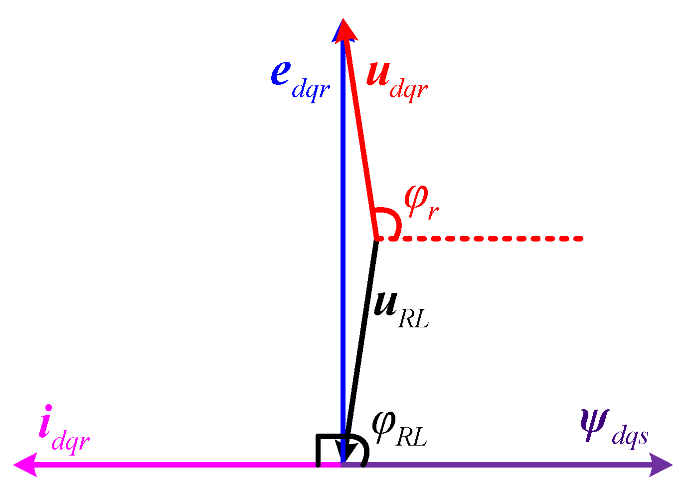
3.1. Rotor Current Request Analysis

When the voltage sags in the grid, the stator flux contains relative stator winding static term and it will be cut by rotor rotation to generate a larger EMF. The attenuation of the transient component should be accelerated to maintain the RSC away from the saturation region. According to Lenz’s law, if there is a current loop on the rotor side, when the stator flux linkage ψ d q s decays, the direction of the magnetic field generated by the rotor current i d q r is the same as that of the stator flux linkage. In other words, the magnetic field slows down the attenuation processes. Therefore, in this case, the current reverse to the stator flux linkage should be injected into the rotor side, which will not only accelerate the attenuation of the stator flux linkage but, according to (2), it will reduce the rotor flux linkage ψ d q r at the same time, and thus reduce the rotor voltage. According to (3), the rotor port vector diagram under the above conditions can be drawn as shown in Figure 3.
As shown in Figure 3, when the rotor current i d q r and stator flux ψ d q s are in opposite directions, the voltage of the rotor is ahead of the stator flux φ r ( φ r > 90 ° ), and the rotor port exhibits inductance characteristics. According to the circuit substitution theorem, RSC can be equivalent to a resistance component and an inductive component in series. In other words, during fault operations, the RSC is equivalent to the inductive impedance by controlling, which can accelerate the RSC away from the saturation region to satisfy the voltage constraint.
The references [19,20,21,22] introduced in Section 1 can make the RSC meet the voltage constraints by improving the control strategy; however, similar to most improved control strategies, these strategies are 2   p . u . for the RSC current constraint, which is the maximum current that the RSC can temporarily withstand [22]. This means that these strategies can hardly provide reactive power support. In addition, there is a hidden danger. In the long run, with an increase in the number of grid faults, if the converter withstands a large current frequently, it may damage the switch tube and increase maintenance costs. Therefore, considering practical applications, it is necessary to find a way to make an RSC withstand low current stress without adding extra cost. The main control target of the GSC under normal conditions is to maintain the DC-bus voltage stable [24]; however, when the grid voltage sags, the RSC will absorb a large amount of active power. The power transmission capacity of the GSC decreases owing to a decrease in the grid voltage. Therefore, these powers cannot be fully sent to the grid, and a large amount of power accumulates on the DC-bus, causing the voltage to increase continuously. To protect the safety of the DC-bus, it is necessary to configure the chopper [25]. Therefore, during grid voltage sag, the GSC control target is difficult to complete, resulting in a significantly reduced GSC utilization rate. However, it is possible to improve the utilization rate of GSC during grid faults by changing the topology of DFIG-based WECS. As shown in Figure 4, power electronic switches S1 and S2 controlled by fault signals are attached to the original topology. Under normal conditions, S1 is closed and S2 is opened, and both of the two converters adopt the traditional vector control strategy. When the grid voltage sags, S1 is opened and S2 is closed, both GSC and RSC are equivalent to inductive impedance through control to share the faulty rotor current. In theory, the current flowing through the GSC and RSC is at most 1   p . u . , it not only improves the utilization rate of the GSC and reduces the risk of RSC damage, but also frees up more current margin to meet the requirement for the reactive current.
According to the above analysis, when the grid voltage drops, the two converters are connected in parallel, and the same control strategy is adopted to make them equivalent to inductive impedance to suppress the faulty rotor current jointly. At this point, it is assumed that the currents flowing through the two converters are equal. Then the equivalent circuit viewed from the rotor side can be shown in Figure 5, where Z e q is the parallel equivalent impedance of the RSC and GSC. This is the basic principle of the proposed DISC strategy. Next, some specific control objectives, such as voltage constraints, current constraints, accelerated flux linkage attenuation, and torque ripple reduction, are analyzed and discussed to select substitution impedance values.

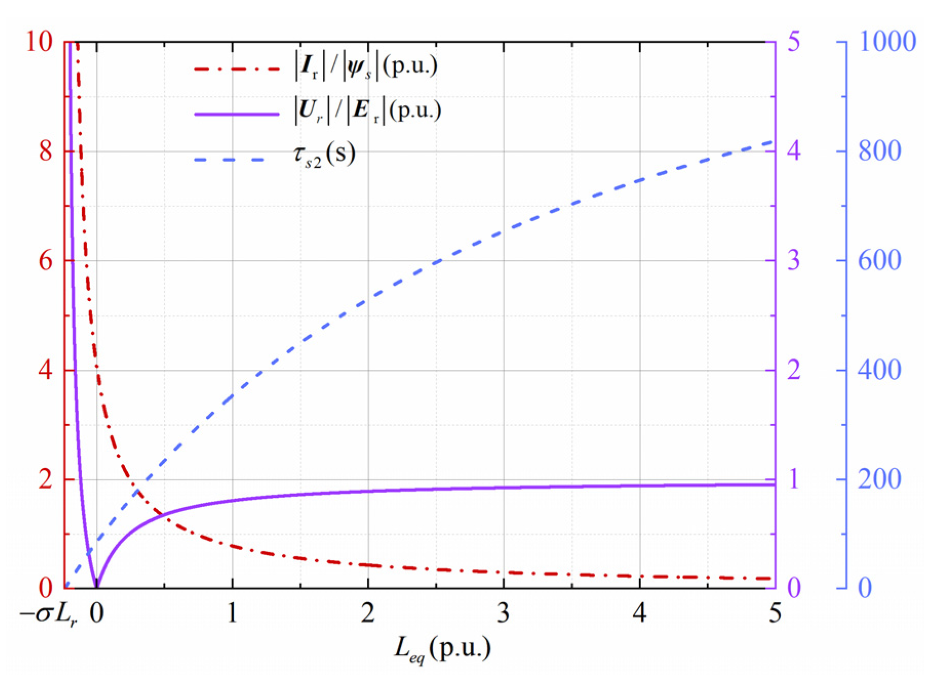
3.2. Double Substitution-Impedance Design

From Figure 3 and the circuit voltage balance theorem, R e q should be equal to R r , and the rotor loop equation can be given by:
L e q ( d d t + j s ω s ) i d q r = L m L s ( d d t + j s ω s ) ψ d q s + σ L r ( d d t + j s ω s ) i d q r
Suppose that the rotor current reference value can be tracked without error. According to (2) and (7), if the rotor port presents inductance characteristics, the rotor current reference can be designed as:
i d q r * = i d q r = L m L s L m 2 + L s ( L e q + σ L r ) i d q s
To prevent an overcurrent on the rotor side, the following equation should be established:
| i d q r | = L m L s L m 2 + L s ( L e q + σ L r ) | i d q s | I r m
where I r m is the maximum rotor current allowed to flow, which is set as 2   p . u . , “| |” is the operation that takes the amplitude. According to (9), L e q can satisfy the Equation (10):
L e q L m ( I s m I r m L m L s ) σ L r
where I s m denotes the maximum stator current during voltage dip. According to (2), the stator current is given below:
i d q s = ψ d q s L m i d q r L s
Due to the opposite direction of rotor current and stator flux vector, the maximum stator current can be further written as:
I s m = ψ s m + L m I r m L s
Here, ψ s m is the maximum value of the stator flux linkage during the grid voltage sag and it appears at the initial moment. According to Figure 5, because R e q and R r cancel each other out, the voltage drop of L e q can be written as:
u L e q = L e q L e q + σ L r e d q r
To prevent RSC and GSC from becoming saturated, there should be:
| u L e q | = L e q L e q + σ L r | e d q r | U r m 2 ( R e q I r m ) 2
where U r m is the RSC and GSC’s allowed output maximum voltage. If space vector pulse width modulation (SVPWM) is used, U r m is the voltage value of the DC-bus [26].
According to (14), L e q can satisfy (15):
L e q σ L r U r m 2 ( R e q I r m ) 2 E r m U r m 2 ( R e q I r m ) 2
where E r m is the maximum EMF value during grid voltage sag.
According to (6), this is the initial value of the sag. By combining (10) and (15), the range of L e q can be obtained as follows:
L m ( I s m I r m L m L s ) σ L r L e q σ L r U r m 2 ( R e q I r m ) 2 E r m U r m 2 ( R e q I r m ) 2
Substituting the simulation parameters in Table 1 into Equation (16), the L e q should satisfy that:
0.246   p . u . L e q 0.308   p . u .
If the grid voltage sags completely, combining (1), (7) and (8), there is the first-order linear differential equation of the stator flux linkage under the DISC strategy as follows:
d d t ψ d q s + [ R s L m 2 + L s ( L e q + σ L r ) L s 2 ( L e q + σ L r ) + j ω s ] ψ d q s = 0
The solution of stator flux linkage in (18) is:
ψ d q s = ψ s m e t τ s 2 e j ω s t
According to (19), the stator flux linkage is a vector attenuated by time constant τ s 2 and rotates with ω s , where the time constant τ s 2 of it can be calculated by (18) as:
τ s 2 = L s 2 ( L e q + σ L r ) R s [ L m 2 + L s ( L e q + σ L r ) ]
According to (9), (14) and (20), the value of L e q is related to the rotor port current, voltage, and attenuation speed of the flux. Taking the most severe fault condition of the system as an example, the grid voltage sags completely and the slip s = 0.3 , E r m and ψ s m are 1.26   p . u . and 1   p . u . , respectively. Figure 6 can be obtained by substituting the parameters in Table 1 and (17) into (9), (14) and (20). According to Figure 6, the rotor port voltage is proportional to L e q , whereas the rotor port current is inversely proportional to L e q , and the time constant τ s 2 is proportional to L e q . The faster the flux linkage attenuation, the easier it meets the requirements of reactive power support in LVRT; thus, the smaller τ s 2 is better. In summary, L e q = 0.246   p . u . is selected. Although the peak current of the rotor port reaches 2   p . u . in the initial stage, the current is evenly distributed by the two converters in series, hence, the current flowing through the RSC or GSC is at most 1   p . u . , at the same time, it not only moves away from the saturation area of the converter but also accelerates the decay of the stator flux linkage, which is the best choice.

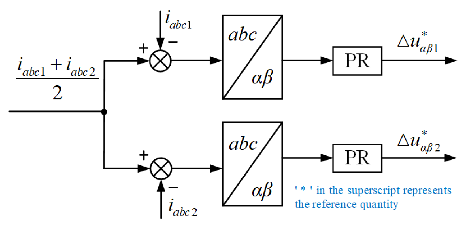
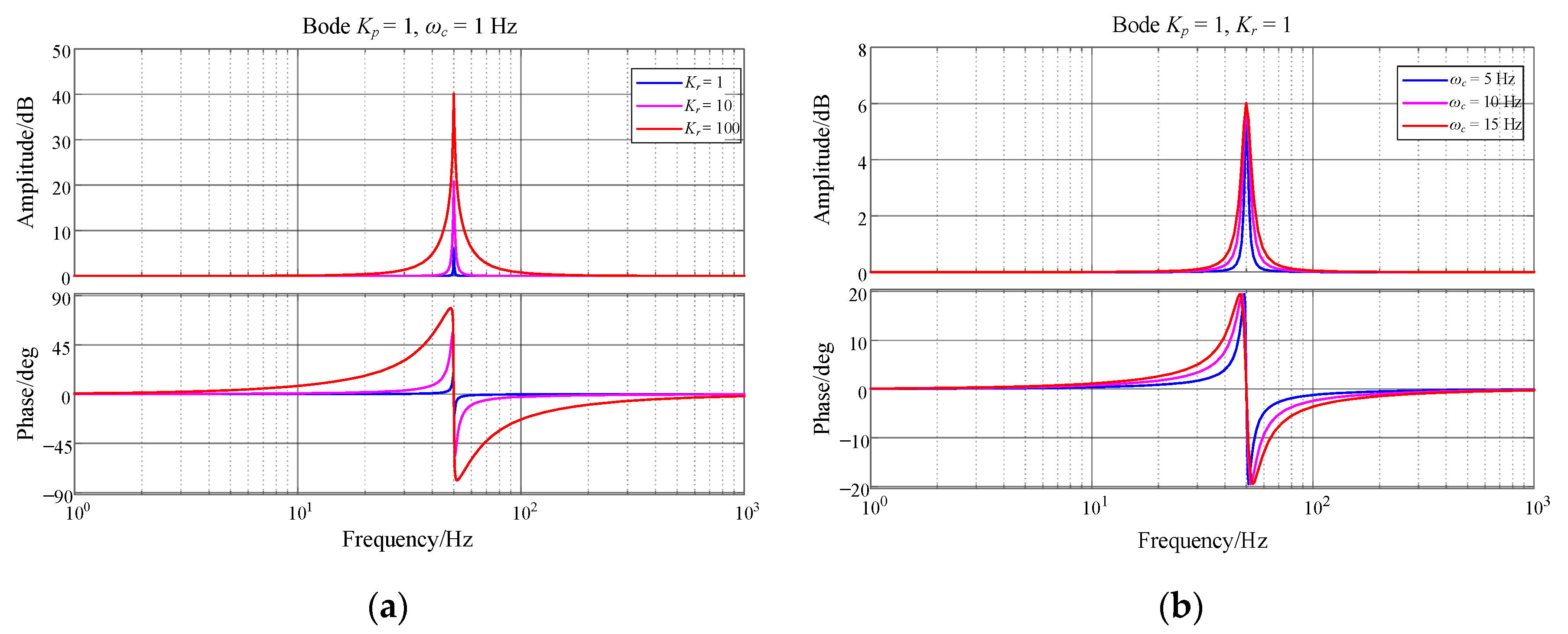
3.3. Instantaneous Current-Sharing Control Strategy

In order to make the inverters parallel perfectly realize current sharing, the amplitude, phase, and frequency of the output voltages of the two inverters should be exactly the same in theory, so that the output currents of the two inverters can be completely equal. However, in the actual operation, because the parameters of each inverter cannot be completely consistent, there are differences in line impedance, or because of the inherent characteristics of the control system, the output voltage of each inverter is not the same, so there will be a voltage difference between the inverters, thus forming a circulating current between the inverters. If the circulating current is large, it will have a destructive impact on the inverter. In this paper, the instantaneous current sharing method is adopted, and a current sharing loop is added on the basis of the traditional control strategy to compensate the unbalanced current by adjusting the output voltage of the two inverters in real-time. The control principle of the current sharing loop is shown in Figure 7.
Since the AC is directly regulated and the gain of PI controller for AC is low, the proportional-resonant (PR) controller is selected, and its transfer function expression is:
G PR ( s ) = K p + 2 K r ω c s s 2 + 2 ω c s + ω 0 2
where: K p is the proportional term coefficient; K r is the resonance term coefficient; ω c and ω 0 are the cut-off frequency and resonance frequency, respectively; cut-off frequency is related to the bandwidth of the controller.
The following Bode diagram analyzes the impact of key parameters in the PR controller on the system, the PR controller and the PI controller K p role, both to improve the open-loop gain, not too much description, set K p constant equal to 1. ω 0 is the resonant frequency, which is set to 50   Hz . As Figure 8a shows, K p and ω c are constant, the peak gain of the PR controller has a positive correlation with the K r . However, the bandwidth of the PR controller does not change, which means that adjusting K r can only adjust the peak gain of the PR controller. From Figure 8b, it can be seen that K p and K r are constant, and when ω c becomes larger, the gain and bandwidth of the PR controller become larger, it shows that the PR controller can still give a larger gain even if there is an error in the frequency when ω c increases.
To validate the credibility of the current sharing strategy, a MATLAB/Simulink platform with a parallel current sharing model is built, which contains two inverters with voltage and current double closed loops. Its rated active power, rated reactive power, rated voltage, rated current, rated frequency and DC-bus voltage are 50   kW , 30   kvar , 380   V , 89   A , 50   Hz and 800   V , respectively. The line impedance of the inverters 1 and 2 are 0.2   Ω and 0.7   Ω , respectively. The switch of the two inverters frequency is 20   kHz . The main circuit part of the system is shown in Figure 9.
The A-phase circulation is defined as:
i a b = i a 1 i a 2
As shown in Figure 10a, when the control strategy of the system does not add the current sharing loop, due to the difference in line impedance, the maximum circulating current reaches 20   A , which is 16% of the peak load current of phase A. The circulating current, if not suppressed, will cause damage to the inverter.
Figure 10b shows the simulation results of the circulating current of the A phase when joining the current sharing loop. It is observed that the circulating current has been significantly suppressed. It is only about 2   A , which only occupies 1.6% of the peak load current of the A phase. The size of the circulation is within the allow able range.
In summary, after adding the current sharing loop, the circulating current of the inverter parallel system can be greatly reduced, which shows the correctness of the current sharing strategy, and further shows that the strategy of using RSC and GSC in parallel to share the rotor overcurrent is feasible.

3.4. The Specific Implementation of the DISC Strategy

According to the foregoing analysis, a schematic of the DFIG control system including the DISC strategy can be drawn, as shown in Figure 11. The actual application is divided into the following two conditions:
(1)
Normal condition
When the grid is in a stable state, S1 is closed and S2 is opened. The control signal of the GSC is provided by switch node 1, and the GSC adopts the grid voltage-oriented control. The current reference in the RSC control strategy is provided by switch node 1, which adopts a stator flux linkage-oriented scheme to implement decoupling control of the power flow between DFIG and the grid.
(2)
Fault condition
When a voltage sag is detected, S1 is opened and S2 is closed. The current reference in the RSC control strategy and the GSC control signal are provided by switch node 2. Both the GSC and RSC adopt the DISC strategy to divide the rotor fault current equally.
At this point, the DC-bus voltage value increases. When V b u s exceeds 1.1   p . u . , the chopper is connected to release energy. It should be noted that if an asymmetrical fault occurs in the grid, the current reference will also contain AC components of 50   Hz and 100   Hz , in addition to the DC component [27]. However, the PI controller gain can hardly be achieved with a zero steady-state error at these frequencies, significantly reducing the effectiveness of the control strategy. To avoid this situation, this paper adopts the feedforward current references control method proposed in [28]. By introducing the feedforward current item, the dynamic response of the current loop can be enhanced, as shown in Figure 11.

3.5. Torque Ripple Analysis

If the torque ripple is too large, it will cause damage to the gearbox; therefore, eliminating torque ripple is an essential target of LVRT. When a constant amplitude transformation is used, the electromagnetic torque can be expressed as:
T e = 1.5 p L m ( i q s i d r i d s i q r )
where p denotes motor pole logarithm. Assuming that the rotor current can accurately track the reference, (8) can be transformed into (23) to obtain:
T e = 1.5 p L m 2 L s L m 2 + L s ( L e q + σ L r ) ( i q s i d s i d s i q s ) = 0
According to (24), the control strategy proposed in this paper can theoretically eliminate torque ripple, thereby increasing the life of the transmission system.

4. Simulation Results

By building a 2-MW DFIG-based WECS simulation platform to demonstrate the effectiveness of the DISC strategy proposed in this paper and compared with the optimized demagnetization control strategy (method-1) proposed in reference [21] and the virtual damping flux-based control strategy (method-2) proposed in reference [19]. The torque imbalance during the grid fault increases the rotor speed, but the rotational inertia of the MW-level DFIG is large, and the duration of the fault is very short, so the rate of change of the speed is very small. It is assumed that the rotor speed is constant [29].

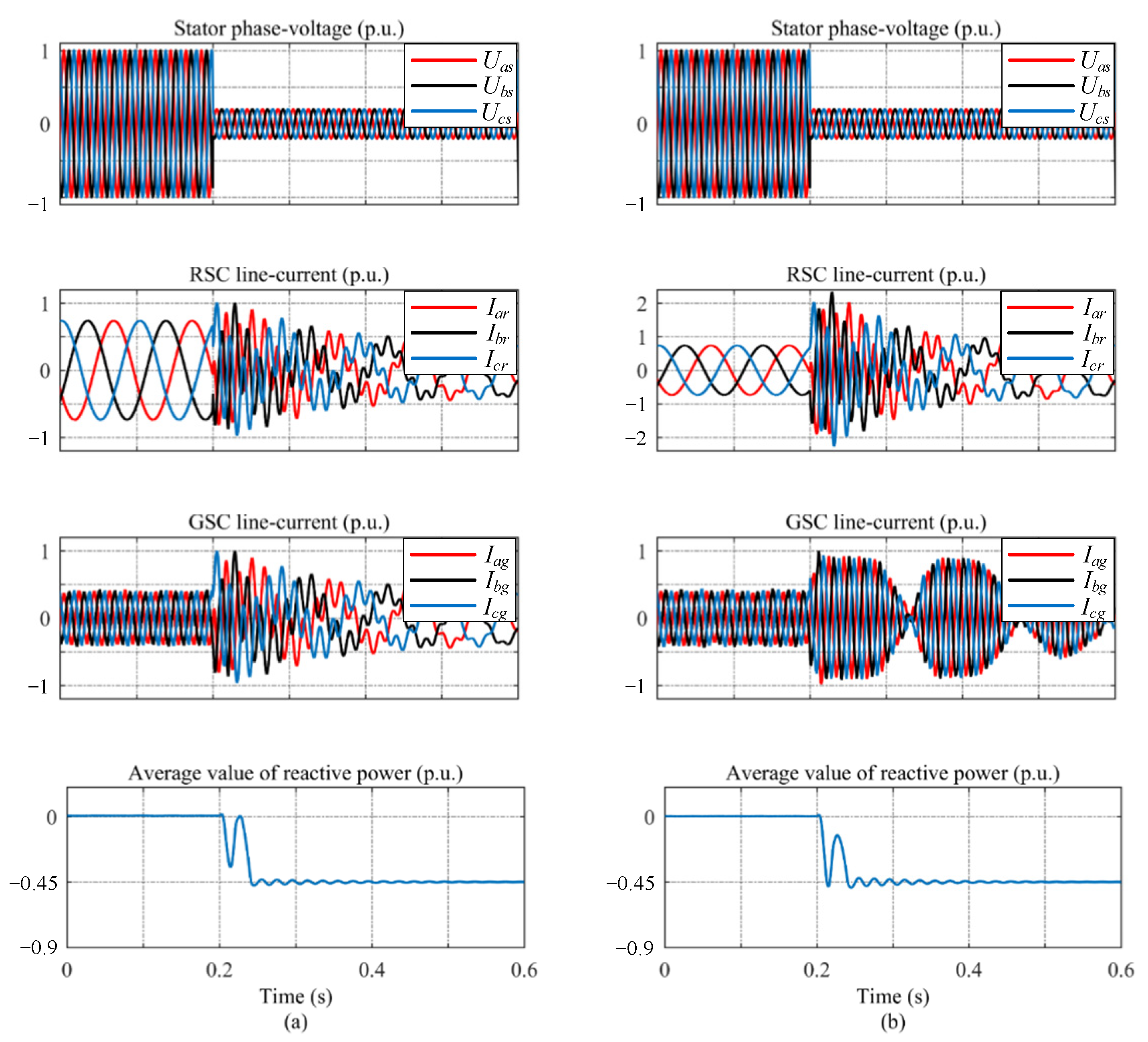
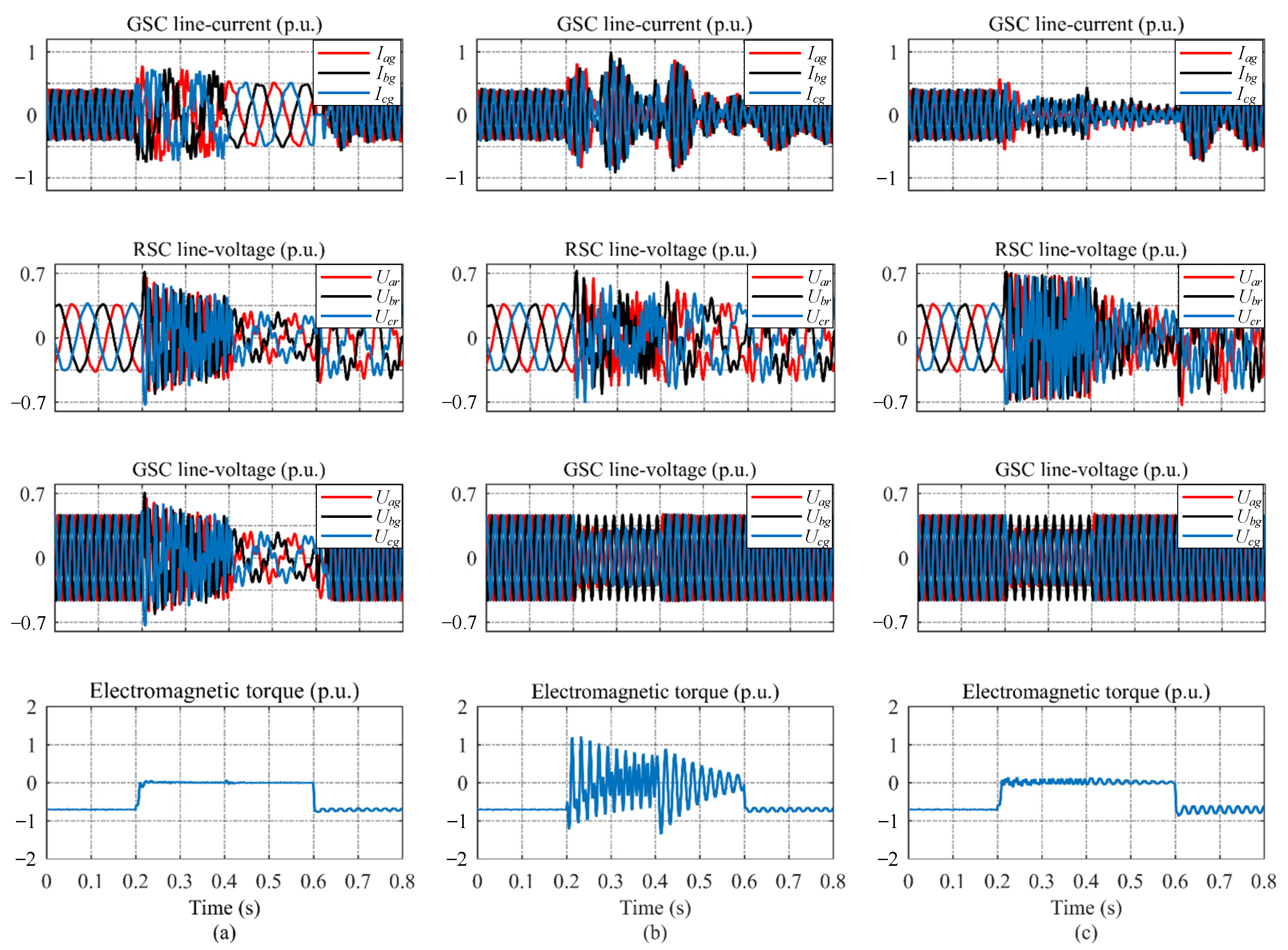
4.1. Symmetrical Faults

First, the control strategy under normal conditions is used to control the operation of the DFIG in super synchronous. The slip s is −0.2, the stator active power P s is 0.7   p . u . , and the reactive power Q s is 0   p . u . , at t = 0.2   s , the grid voltage sags symmetrically to 0.2   p . u . , and at t = 0.4   s , the grid voltage is restored completely. When the grid voltage sag is detected, it quickly switches to the LVRT control strategy to ensure the continuous operation of the DFIG without disconnection. Because the voltage sag and restore will make the flux linkage contain a transient component, these control strategies will be restored to the state before the fault during t = 0.6   s . The simulation results are shown in Figure 12.
Comparative analysis from the perspective of voltage constraints, whether the actual output voltage value of RSC and GSC exceeds its maximum allowable value U r m is the basis for judging whether the converter is saturated, because U r m depends on the DC-bus voltage value, according to Table 1, V b u s is 1200 V, then U r m is about 0.71   p . u . . According to Figure 12, the DISC, method-1 and method-2 can all meet the voltage constraint, but the three are different. during a grid fault, the RSC request voltage in method-1 is the minimum. This is because the demagnetization current is large, and a large voltage drop is generated in the rotor impedance, which offsets most of the EMF. The RSC request voltage in method-2 is the maximum, which is within the tolerable range during the fault period. However, when the grid is restored and the control strategy is switched to the normal control strategy, the RSC request voltage increases, which is very close to the critical point of the voltage constraint. The DISC’s RSC request voltage is between method-1 and method-2 and is always within a safe range. In addition, from the output voltage of the GSC in method-1 and method-2, it can be seen that the output voltage of the GSC is also reduced owing to the grid voltage sag, which results in the limitation of the active power output capacity. The utilization of the GSC is significantly reduced, which further explains the rationality of dividing the fault current equally between the GSC and RSC in parallel.
From the perspective of current constraints, according to Figure 12, the three control strategies can suppress the rotor-side current within ± 2   p . u . under symmetrical fault. However, it can be seen from Figure 12a that the DISC uses the RSC and GSC to share the overcurrent of the rotor side in parallel, so the current flowing through the RSC and GSC is within ± 1   p . u . , to avoid damage to the converter owing to high current stress, enhance the system reliability, and reduce the maintenance cost. In addition, in DISC, when the grid is restored and the control strategy is switched to the normal control strategy, the output current of the GSC can reach a steady state after 0.1   s . Method-1 is to inject the current opposite to the stator flux linkage transient component into the rotor current reference to accelerate the flux linkage attenuation. According to Figure 12b, the demagnetization current is large, which puts the RSC in a state of high current stress for a long time, and it is easy to have the risk of overcurrent. According to Figure 12c, during a grid fault, the RSC output current of method-2 is smaller than that of method-1. However, method-2 and method-1 had the same hidden dangers. The output current of the GSC cannot quickly reach a steady state after the grid is restored, and an excessive pulsating current may also damage the converter.
According to the analysis in Section 3, from the perspective of torque ripple, if the actual value of the rotor current can accurately track the reference value, DISC can eliminate the torque ripple, as shown in Figure 12a. The torque ripple is relatively smooth during the fault, which demonstrates the correctness of the previous analysis. The demagnetization current in method-1 does not contain a positive-sequence component, but the stator current contains a positive-sequence component. Therefore, according to (23), it can be known that there is a torque ripple of 50   Hz in the demagnetization control. Method-2 can theoretically eliminate torque ripple; however, in method-2, PI-R is used instead of PI as the current controller. For the control of AC components, PI-R can achieve better control effects than PI, but there is still a certain error, so a torque ripple is generated.
In conclusion, the control strategy proposed in this study considers current constraints, voltage constraints, safe operation of the converter, torque ripple suppression, and other aspects. A comparison with the existing control strategy shows that the control strategy proposed in this paper can better improve the LVRT capability of the DFIG.

4.2. Single-Phase Faults

The most common fault in a grid is single-phase sag. In contrast to a three-phase symmetrical sag, the stator flux linkage contains an additional negative-sequence component when grid voltage occurs in a single-phase sag. The negative-sequence component presents a 100   Hz AC characteristic in the dq coordinate system and generates a large EMF. If it is not properly controlled, it is likely to saturate the converter. Figure 13 shows the simulation result of an 80% single-phase sag of grid voltage, which can still restrain the current flowing through the converter within ± 1   p . u . , and the RSC and GSC are in a controllable state, which can accurately control the rotor current. The simulation results of method-1 and method-2 are similar to the simulation results under symmetrical faults. It is worth noting that under single-phase faults, owing to the existence of transient and negative-sequence components, there are 50   Hz and 100   Hz torque ripples under method-1. The output voltage of the RSC in method-2 is very close to the critical value of the voltage constraint, which may cause the converter to lose control. In conclusion, the simulation results are consistent with the simulation results of symmetrical faults, which further demonstrates the effectiveness of the proposed control strategy.

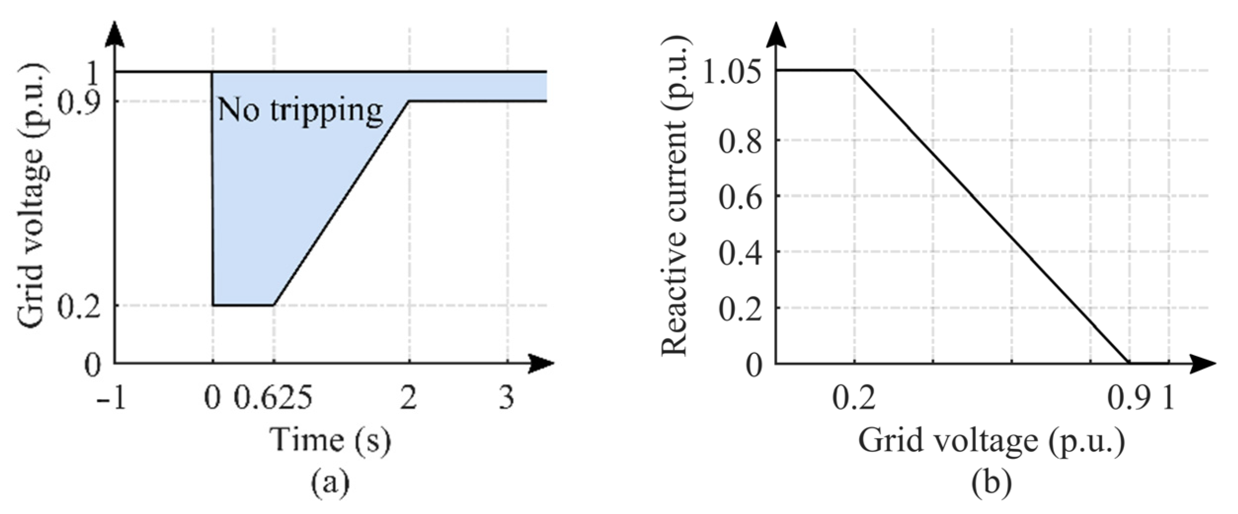
4.3. Assessment of Reactive Power Support Capacity

The magnitude of the required reactive current is shown in Figure 1b. This shows that the magnitude of the reactive current is related to the grid sag depth h . When the RSC adopts the stator flux linkage-oriented control, the expression of the stator-side reactive power Q s is [19].
Q s = 1.5 [ ( h U m ) 2 ω s L s h U m L m L s i dr ]
It is taking the symmetrical sag of the grid voltage by 80% as an example, according to Figure 1b and (25), the reactive power that should be injected into the grid is about − 0.45   p . u . In order to verify whether the control strategy proposed in this paper can meet the reactive power requirements of the wind power grid connection standard, this section adds new conditions based on the simulated conditions in Section 4.1, that is, after the grid voltage sags 20   ms , the DFIG injects into the grid 0.45   p . u . of reactive power until the grid restores to normal. A comparison of the simulation result with method-1 is shown in Figure 14.
According to Figure 14, both the DISC and method-1 can respond to reactive power commands faster, causing the DFIG to send out 0.45   p . u . of reactive power, indicating that neither control strategy has lost control of the system. However, the current flowing through the RSC in method-1 exceeds 2   p . u . The main reason is that the demagnetization current itself is already very large, and after the reactive current is superimposed, a severe overcurrent can easily occur in the RSC, which will damage the converter. In other words, in practical applications, the system will carry out overcurrent protection and must be stopped. Therefore, it is difficult to meet the reactive power support only by method-1, and an additional reactive power compensation device is required, which increases the additional costs. In contrast, the DISC proposed in this paper, in the case of meeting the reactive power required, the current flowing through RSC and GSC can still be suppressed within ± 1   p . u . , the converter is always running within a safe range, does not require additional auxiliary devices, and greatly increases the reliability of the system.

5. Conclusions

When a severe fault occurs in the grid, the RSC of the DFIG-based WECS withstands high current stress, and it is difficult to meet the reactive support. To solve this problem, this paper proposes a DISC strategy without flux linkage observation to improve the LVRT capability of the system. The main conclusions are summarized as follows.
(1)
When a severe fault occurs in the grid, without proper control, the EMF causes the RSC to saturate and lose control of the system. Therefore, evaluating whether an LVRT control strategy is valid depends on whether the RSC under this strategy is saturated.
(2)
Based on Lenz’s law analysis of rotor port characteristics, it is concluded that during LVRT, by controlling the rotor current and stator flux linkage to reverse, the RSC is the most difficult to saturate. At this point, the RSC is equivalent to the inductive impedance, and the torque ripple can also be eliminated.
(3)
during a grid fault, considering that the current stress withstood by the RSC is large, and the utilization rate of the GSC is very low, this paper proposes a DISC strategy. Under the condition that the grid voltage sags by 80%, unlike the existing control strategy, the DISC strategy can maintain the current flowing through the RSC and GSC within ± 1   p . u .
(4)
If the DFIG meets the reactive power requirements during LVRT, the RSC must have a sufficient current margin at the beginning of the fault. Otherwise, an excessive current damages the RSC and causes severe losses.

Author Contributions

Conceptualization; Supervision; Writing—Review & Editing; Project Administration, Y.Z.; Writing—original draft; Investigation; Methodology; Validation, J.L.; Visualization, M.Z.; Software, C.L.; Data Curation, Y.L. All authors have read and agreed to the published version of the manuscript.

Funding

This work was supported by the Natural Science Foundation of Heilongjiang Province (No. TD2021E002) and the National Natural Science Foundation of China under the Grant (No. U21A20145).

Institutional Review Board Statement

Not applicable.

Informed Consent Statement

Not applicable.

Data Availability Statement

Not applicable.

Acknowledgments

The authors gratefully acknowledge the contributions of the Natural Science Foundation of Heilongjiang Province (No. TD2021E002) and the National Natural Science Foundation of China under the Grant (No. U21A20145).

Conflicts of Interest

The authors declare no conflict of interest.

References

  1. Mahela, O.P.; Gupta, N.; Khosravy, M.; Patel, N. Comprehensive Overview of Low Voltage Ride Through Methods of Grid Integrated Wind Generator. IEEE Access 2019, 7, 99299–99326. [Google Scholar] [CrossRef]
  2. Rahimi, M. Analytical assessment of the impact of stator-series passive resistive hardware (SSPRH) on transient response and fault current contribution in DFIG based wind turbines. Electr. Power Syst. Res. 2019, 177, 105959. [Google Scholar] [CrossRef]
  3. Zou, X.; Zhu, D.; Hu, J.; Zhou, S.; Kang, Y. Mechanism Analysis of the Required Rotor Current and Voltage for DFIG-Based WTs to Ride-Through Severe Symmetrical Grid Faults. IEEE Trans. Power Electron. 2018, 33, 7300–7304. [Google Scholar] [CrossRef]
  4. Geng, H.; Liu, C.; Yang, G. LVRT Capability of DFIG-Based WECS Under Asymmetrical Grid Fault Condition. IEEE Trans. Ind. Electron. 2013, 60, 2495–2509. [Google Scholar] [CrossRef]
  5. Amalorpavaraj, R.A.J.; Kaliannan, P.; Padmanaban, S.; Subramaniam, U.; Ramachandaramurthy, V.K. Improved Fault Ride Through Capability in DFIG Based Wind Turbines Using Dynamic Voltage Restorer with Combined Feed-Forward and Feed-Back Control. IEEE Access 2017, 5, 20494–20503. [Google Scholar] [CrossRef]
  6. Meegahapola, L.G.; Littler, T.; Flynn, D. Decoupled-DFIG Fault Ride-Through Strategy for Enhanced Stability Performance during Grid Faults. IEEE Trans. Sustain. Energy 2010, 1, 152–162. [Google Scholar] [CrossRef] [Green Version]
  7. Xie, D.L.; Xu, Z.; Yang, L.H.; Ostergaard, J.; Xue, Y.S. A Comprehensive LVRT Control Strategy for DFIG Wind Turbines with Enhanced Reactive Power Support. IEEE Trans. Power Syst. 2013, 28, 3302–3310. [Google Scholar] [CrossRef]
  8. Firouzi, M.; Gharehpetian, G.B. LVRT Performance Enhancement of DFIG-Based Wind Farms by Capacitive Bridge-Type Fault Current Limiter. IEEE Trans. Sustain. Energy 2018, 9, 1118–1125. [Google Scholar] [CrossRef]
  9. Guo, W.Y.; Xiao, L.Y.; Dai, S.T.; Li, Y.H.; Xu, X.; Zhou, W.W.; Li, L. LVRT Capability Enhancement of DFIG with Switch-Type Fault Current Limiter. IEEE Trans. Ind. Electron. 2015, 62, 332–342. [Google Scholar] [CrossRef]
  10. Zou, Z.C.; Liao, J.C.; Lei, Y.; Mu, Z.L.; Xiao, X.Y. Postfault LVRT Performance Enhancement of DFIG Using a Stage-Controlled SSFCL-RSDR. IEEE Trans. Appl. Supercond. 2019, 29, 5601306. [Google Scholar] [CrossRef]
  11. Yan, X.W.; Venkataramanan, G.; Wang, Y.; Dong, Q.; Zhang, B. Grid-Fault Tolerant Operation of a DFIG Wind Turbine Generator Using a Passive Resistance Network. IEEE Trans. Power Electron. 2011, 26, 2896–2905. [Google Scholar] [CrossRef]
  12. Xiao, X.Y.; Yang, R.H.; Zheng, Z.X.; Wang, Y. Cooperative Rotor-Side SMES and Transient Control for Improving the LVRT Capability of Grid-Connected DFIG-Based Wind Farm. IEEE Trans. Appl. Supercond. 2019, 29, 0600204. [Google Scholar] [CrossRef]
  13. Jabbour, N.; Tsioumas, E.; Mademlis, C.; Solomin, E. A Highly Effective Fault-Ride-Through Strategy for a Wind Energy Conversion System with a Doubly Fed Induction Generator. IEEE Trans. Power Electron. 2020, 35, 8154–8164. [Google Scholar] [CrossRef]
  14. Liang, J.Q.; Howard, D.F.; Restrepo, J.A.; Harley, R.G. FeedForward Transient Compensation Control for DFIG Wind Turbines during both Balanced and Unbalanced Grid Disturbances. IEEE Trans. Ind. Appl. 2013, 49, 1452–1463. [Google Scholar] [CrossRef]
  15. Vrionis, T.D.; Koutiva, X.I.; Vovos, N.A. A Genetic Algorithm-Based Low Voltage Ride-Through Control Strategy for Grid Connected Doubly Fed Induction Wind Generators. IEEE Trans. Power Syst. 2014, 29, 1325–1334. [Google Scholar] [CrossRef]
  16. Mohseni, M.; Islam, S.M. Transient Control of DFIG-Based Wind Power Plants in Compliance with the Australian Grid Code. IEEE Trans. Power Electron. 2012, 27, 2813–2824. [Google Scholar] [CrossRef]
  17. Villanueva, I.; Rosales, A.; Ponce, P.; Molina, A. Grid-Voltage-Oriented Sliding Mode Control for DFIG Under Balanced and Unbalanced Grid Faults. IEEE Trans. Sustain. Energy 2018, 9, 1090–1098. [Google Scholar] [CrossRef]
  18. Lima, F.K.A.; Luna, A.; Rodriguez, P.; Watanabe, E.H.; Blaabjerg, F. Rotor Voltage Dynamics in the Doubly Fed Induction Generator during Grid Faults. IEEE Trans. Power Electron. 2010, 25, 118–130. [Google Scholar] [CrossRef] [Green Version]
  19. Zhu, R.W.; Chen, Z.; Wu, X.J.; Deng, F. Virtual Damping Flux-Based LVRT Control for DFIG-Based Wind Turbine. IEEE Trans. Energy Convers. 2015, 30, 714–725. [Google Scholar] [CrossRef]
  20. Zhou, L.Y.; Liu, J.J.; Zhou, S.Z. Improved Demagnetization Control of a Doubly-Fed Induction Generator Under Balanced Grid Fault. IEEE Trans. Power Electron. 2015, 30, 6695–6705. [Google Scholar] [CrossRef]
  21. Zhou, D.; Blaabjerg, F. Optimized Demagnetizing Control of DFIG Power Converter for Reduced Thermal Stress during Symmetrical Grid Fault. IEEE Trans. Power Electron. 2018, 33, 10326–10340. [Google Scholar] [CrossRef] [Green Version]
  22. Shen, Y.W.; Ke, D.P.; Qiao, W.; Sun, Y.Z.; Kirschen, D.S. Transient Reconfiguration and Coordinated Control for Power Converters to Enhance the LVRT of a DFIG Wind Turbine with an Energy Storage Device. IEEE Trans. Energy Convers. 2015, 30, 1679–1690. [Google Scholar] [CrossRef]
  23. Ali, M.A.S.; Mehmood, K.K.; Baloch, S.; Kim, C.H. Modified rotor-side converter control design for improving the LVRT capability of a DFIG-based WECS. Electr. Power Syst. Res. 2020, 186, 106403. [Google Scholar] [CrossRef]
  24. Din, Z.; Zhang, J.Z.; Zhu, Y.D.; Xu, Z.; El-Naggar, A. Impact of Grid Impedance on LVRT Performance of DFIG System with Rotor Crowbar Technology. IEEE Access 2019, 7, 127999–128008. [Google Scholar] [CrossRef]
  25. Pannell, G.; Zahawi, B.; Atkinson, D.J.; Missailidis, P. Evaluation of the Performance of a DC-Link Brake Chopper as a DFIG Low-Voltage Fault-Ride-Through Device. IEEE Trans. Energy Convers. 2013, 28, 535–542. [Google Scholar] [CrossRef]
  26. Zhu, D.H.; Zou, X.D.; Deng, L.; Huang, Q.J.; Zhou, S. Inductance-Emulating Control for DFIG-Based Wind Turbine to Ride-Through Grid Faults. IEEE Trans. Power Electron. 2017, 32, 8514–8525. [Google Scholar] [CrossRef]
  27. LÓpez, J.; GubÍa, E.; Sanchis, P.; Roboam, X.; Marroyo, L. Wind Turbines Based on Doubly Fed Induction Generator Under Asymmetrical Voltage Dips. IEEE Trans. Energy Convers. 2008, 23, 321–330. [Google Scholar] [CrossRef]
  28. Zhu, D.H.; Zou, X.D.; Zhou, S.Y.; Dong, W.; Kang, Y.; Hu, J.B. Feedforward Current References Control for DFIG-Based Wind Turbine to Improve Transient Control Performance during Grid Faults. IEEE Trans. Energy Convers. 2018, 33, 670–681. [Google Scholar] [CrossRef]
  29. Zhu, D.H.; Zou, X.D.; Dong, W.; Jiang, C.C.; Kang, Y. Disturbance feedforward control for type-3 wind turbines to achieve accurate implementation of transient control targets during LVRT. Int. J. Electr. Power Energy Syst. 2020, 119, 105954. [Google Scholar] [CrossRef]
Figure 1. LVRT requirements (a) Continuous operation area. (b) Reactive current.
Energies 15 05739 g001
Figure 2. The equivalent circuit on the rotor side.
Energies 15 05739 g002
Figure 3. Rotor port vector diagram.
Energies 15 05739 g003
Figure 4. The topology of DFIG-based WECS.
Energies 15 05739 g004
Figure 5. Equivalent circuit of the rotor side under the proposed strategy.
Energies 15 05739 g005
Figure 6. Relationship between Leq and rotor port current, voltage, the time constant of stator flux.
Energies 15 05739 g006
Figure 7. Schematic diagram of current-sharing loop control.
Energies 15 05739 g007
Figure 8. (a) Bode diagram of PR controller when parameter Kr changes. (b) Bode diagram of PR controller when parameter ωc changes.
Energies 15 05739 g008
Figure 9. Main circuit of double inverter parallel current sharing simulation model.
Energies 15 05739 g009
Figure 10. (a) A-phase circulation without current equalization loop. (b) A-phase circulation when joining the current equalizing ring.
Energies 15 05739 g010
Figure 11. Schematic diagram of the DFIG control system with DISC strategy.
Energies 15 05739 g011
Figure 12. Simulation results of three-phase grid voltage sag of 80%. (a) DISC. (b) Method-1. (c) Method-2.
Energies 15 05739 g012aEnergies 15 05739 g012b
Figure 13. Simulation results of single-phase grid voltage sag of 80%. (a) DISC. (b) Method-1. (c) Method-2.
Energies 15 05739 g013aEnergies 15 05739 g013b
Figure 14. Reactive support capacity. (a) DISC. (b) Method-1.
Energies 15 05739 g014
Table 1. Parameters of 2-MW DFIG.
SymbolParameterValuePer-Unit
PsRated stator power2 MW
UsRated stator voltage690 V
IsRated stator current1760 A
fsRated stator frequency50 Hz
VbusRated DC-bus voltage1200 V
pPoles pairs2
uTurn ratio (Ns/Nr)1/3
RsStator resistance0.026 Ω0.0115 p.u.
RrRotor resistance0.029 Ω0.0128 p.u.
LmMutual inductance2.5 mH3.4699 p.u.
LStator leakage inductance0.087 mH 0.1208 p.u.
LRotor leakage inductance0.087 mH 0.1208 p.u.
Publisher’s Note: MDPI stays neutral with regard to jurisdictional claims in published maps and institutional affiliations.

