1. Introduction
Researchers have attempted to achieve greater efficiency for mobile platforms such as excavators [
1], robots [
2], and quadrupeds [
3]. A constant-pressure valve-controlled hydraulic system presented in [
4] has a nine-times greater peak input power than a variable-pressure pump-controlled hydraulic system performing the same task. The challenges of pump-controlled hydraulic systems, such as load–pressure variance for load-sensing hydraulics [
5] and poor tracking for displacement control hydraulics, have been investigated [
6]. A pump-controlled rotary hydraulic actuation system efficiency has been improved for the drivetrains of mobile platforms [
7,
8,
9,
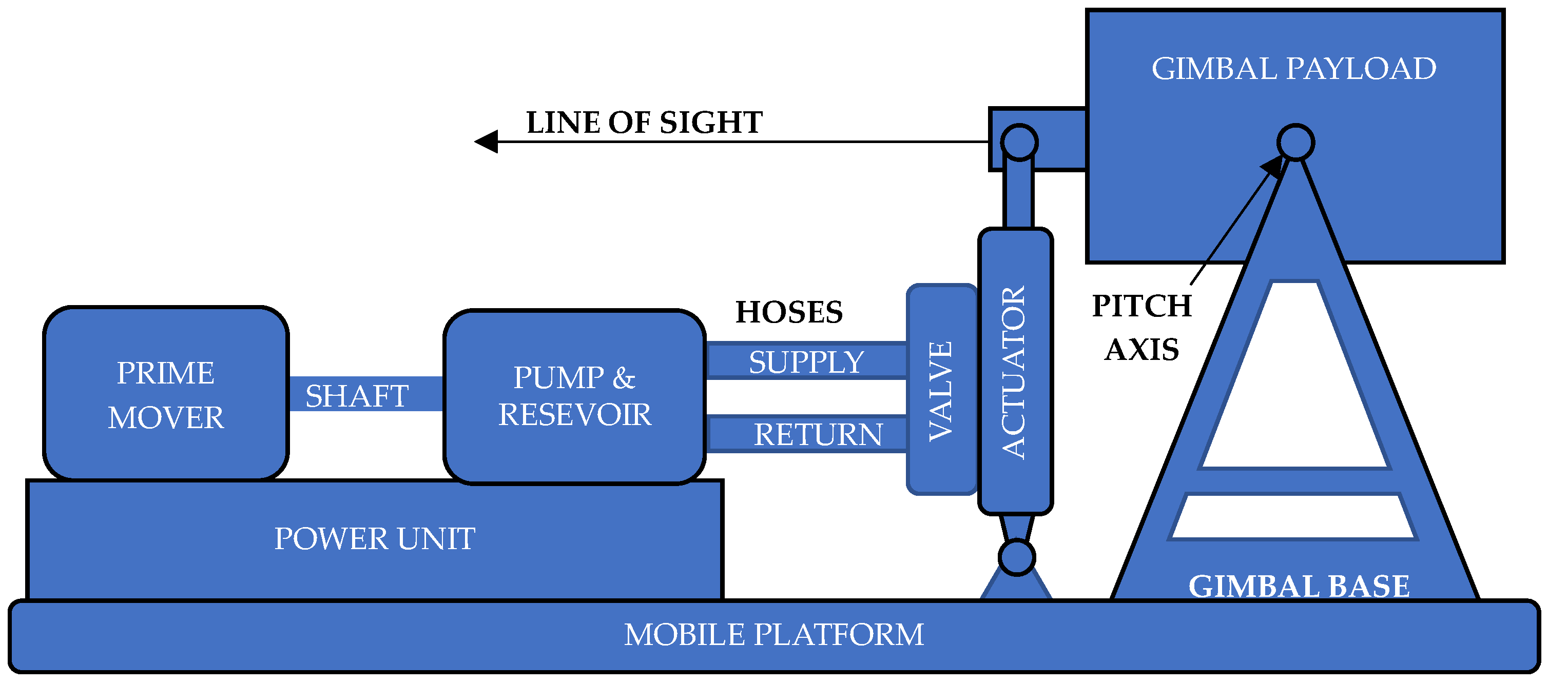
10]. In this paper, we focus on a valve-controlled linear hydraulic actuation system in
Figure 1 with a single actuator because it represents a common system design found on mobile platforms with good tracking performance.
The theoretical maximum hydraulic system power-transfer efficiency (PTE) (excluding the prime mover and pump) for valve-controlled hydraulic systems at maximum power output is 66.7%, while pump-controlled hydraulic systems achieve even higher PT [
11] In general, efficient hydraulic systems consume less energy, independent of the power source, by meeting two requirements: first, by accurately matching peak output power capability to the peak load power requirement, and second, by maximizing PTE. Therefore, given the peak load power requirement, both peak output-power capability and PTE dictate the size, weight, and power of a hydraulic system.
We present an automated sizing technique that maximizes PTE by minimizing hydraulic system peak input power while meeting the peak load power requirement. The common valve-controlled architecture includes constant-pressure and variable-flow control and establishes a baseline configuration to which pump-controlled architectures may be compared. We use a modeling framework including parameters for both the plant and control law to minimize peak input power as computed using the product of instantaneous hydraulic-system pump outlet pressure and flow. For constant-pressure systems, minimizing peak flow will minimize peak input power. The peak flow, in turn, is minimized by minimizing actuator displacement, which is what we aim for here. We show that a single inequality constraint limits hydraulic system PTE, and a path exists for improvement through system-design innovation using an inerter. What is significant is that while the baseline architecture represents the most power-dense actuation system design, we find and present a path to a more power-dense architecture through our proposed innovation using the inerter.
2. Materials and Methods: System Design Optimization
The control objective we chose was disturbance rejection. We characterized the environmental disturbance by its power spectral density (PSD) and used it to evaluate the candidate system designs through analysis. The analysis involved converting random base motion, using the frequency transfer function (FTF) representing the plant and control-law dynamics [
12], to a jitter estimate as a stabilization measure of performance. We defined base motion as the rotational rate about the pitch axis under a platform-mounted, inertially-stabilized equipment mount. We modeled the closed-loop disturbance rejection or closed-loop regulation (CLR) control in the frequency domain with the FTF. This analysis technique achieved automatic system design parameter selection for both the plant and control law to address the CLR of load motion for the given architecture. We set the load–motion servo rate command to zero. We derived our plant model from [
13] and refined it by selecting a flow–pressure coefficient formula and control law for the architecture. We quantified the jitter as the root mean square (RMS) rotational position response of the stabilized mount to the rate disturbance.
2.1. Optimization Objective and Constraints
Our mathematical optimization model involved a single objective for minimizing actuator displacement. In our optimization formulation, we have four inequality constraints and two equations that relate variables to the constrained parameters and the objective. The first inequality constraint limits jitter to a maximum of 0.006 mrad. The second inequality constraint limits the phase margin (PM) to a minimum of 30°. The third inequality constraint limits the gain margin (GM) to a minimum of 6 dB. The fourth inequality constraint involves a quantity we define as the
frequency ratio, which is the ratio of the hydraulic system’s first natural frequency (FNF) and the open-loop servo (OLS) FTF crossover frequency. The inequality constraint assures that the frequency ratio is at least 3.5, which is a heuristic design rule provided in [
14] (p. 240). This constraint assures sufficient gain margin at the peak amplitude associated with poor damping of the hydraulic system FNF. The first equation uses the CLR FTF and PSD to compute jitter. Finally, the second equation is the OLS FTF, which was derived from the CLR FTF. The magnitude and phase equations were derived from the complex-valued OLS FTF and used to compute magnitude, crossover frequency, GM, phase, and PM.
The frequency-ratio constraint limit of 3.5 was a conventional value applied to the designs [
14]. However, it is possible for a design to violate this constraint and still be valid, though this is not widely recognized. This paper discusses this claim in detail. More specifically, we discuss how incorporating an inerter addresses the risks that originally motivated the constraint limit of 3.5.
2.2. Constraints and the Trade Space
As stated earlier, we define peak input power as the peak product of instantaneous flow and pressure at the outlet of the system pump. The flow rate determines the pump output power for constant-pressure valve-controlled hydraulic systems. We minimized peak input power by minimizing peak flow, which, in turn, can be achieved by minimizing the actuator displacement. Solving the optimization problem balances the set of system design parameters to maximize PTE. We expected that the bandwidth, which is represented by the OLS FTF crossover frequency, would always be limited by the damping of linear hydraulic actuation with a damping factor of 0.1 or less [
15] (p. 342).
2.3. Equation Coupling
The proportional–integral (PI) control-law and loop gains were selected in the solution to minimize the hydraulic actuator displacement about the pitch axis while achieving the required stabilization. This equation includes a fixed radius to the centerline of the linear hydraulic actuator, so the piston area is the only way that actuator displacement can be changed by the solver.
2.4. System Modeling
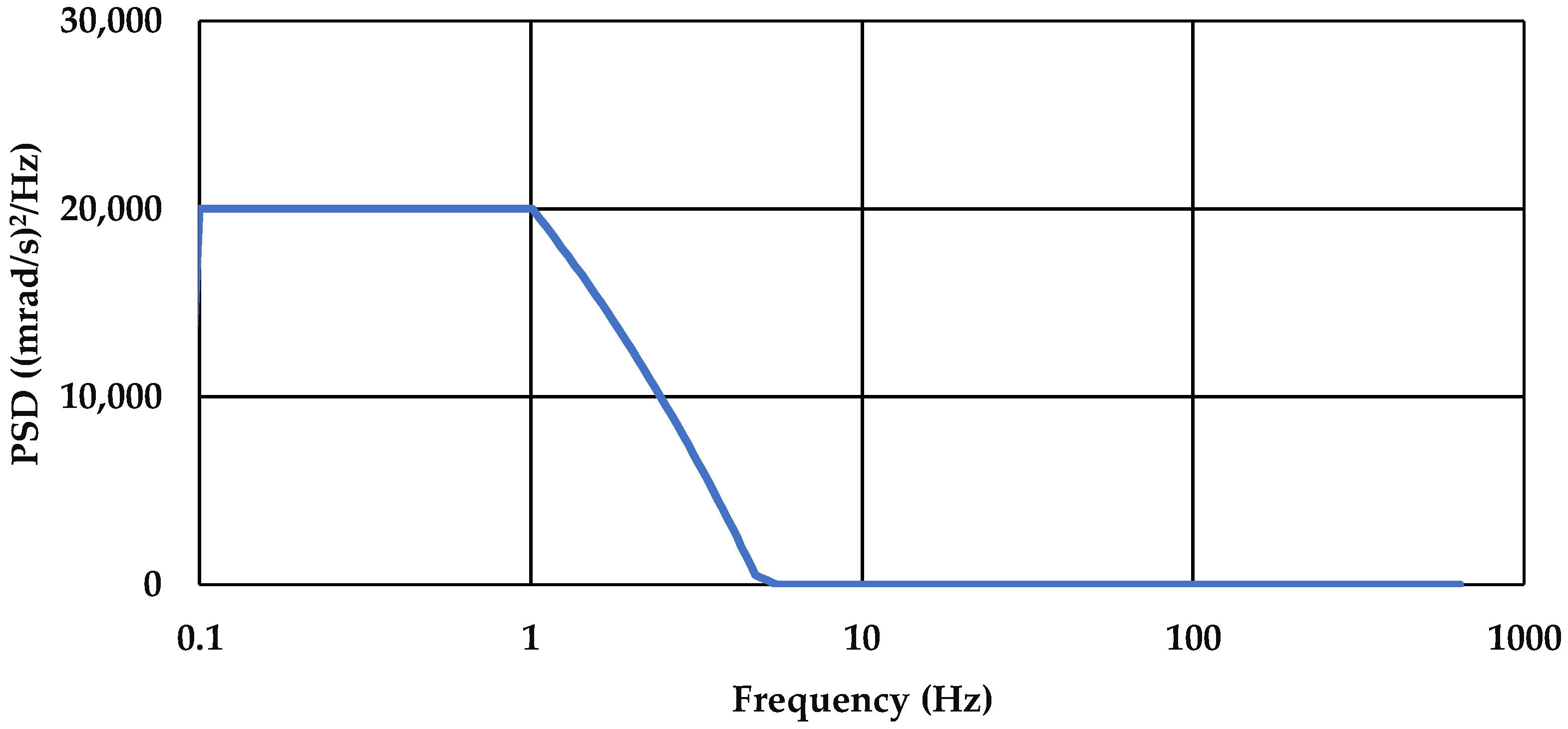
A PSD of the pitch axis disturbance source characterizes the base motion at the actuator housing, given the definition established in [
13].
Figure 2 shows a plot of the PSD
where
represents frequency. Both the PSD
and the dimensionless CLR FTF
with integrator
are factors (where
and
) in
The integrator provides a way to compute the axis rotational position from the rate. Equation (1) provides the pitch-axis RMS rotational position jitter squared.
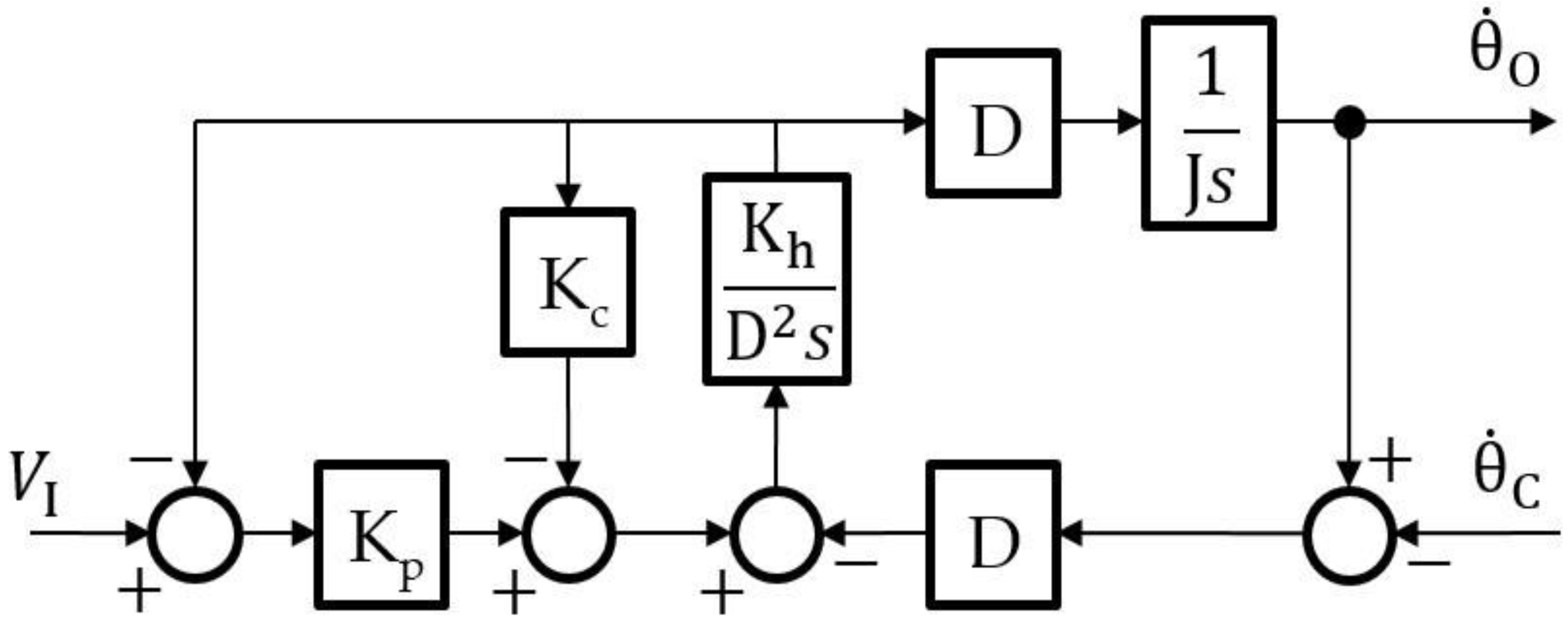
The transfer function
may be derived from the block diagram in
Figure 3. First, define
as the pressure gain and control law block [
13]. The hydraulic stiffness
includes
as the effective bulk modulus,
is the actuator displacement, and
as the hydraulic fluid volume inside the actuator on one side of the piston, where
. The flow–pressure coefficient is computed as
where
is the system pressure for the constant-pressure system,
is the valve port area,
is the dimensionless orifice coefficient, and
is the hydraulic fluid density [
14] (p. 87). The stabilized mount and payload mass moment of inertia is
. The displacement
is the product of
and radius to the actuator centerline
. In
Figure 3,
is the servo input (command),
is the disturbance rotational rate, or regulation input,
is the stabilized mount and payload rate output in the effective inertial reference frame, and
is the Laplace operator set equal to
in the FTF, where
has units of radian/second and
has units of Hz.
Appendix A lists the design parameter units of measurement.
Given the parameters defined in the previous paragraph, the derived CLR FTF is
Our system design optimization (SDO) technique employed nonlinear programming (NLP) and frequency-domain analysis as follows:
We derived the parameters with reduced subjectivity for the most efficient system design to analyze the valve-controlled constant-pressure closed-circuit hydraulic system design from the literature for an inertially stabilized mount. The flow–pressure coefficient was selected to be consistent with a critical-center 4-way valve. The pump was a variable displacement, axial-piston pump. The power source provided shaft power at a constant speed to the pump, which delivered variable flow and constant pressure by regulating pump displacement.
The solver traversed the feasible region of the solution space using the Generalized Reduced-Gradient (GRG) algorithm by Frontline Systems, Inc. (San Antonio, TX, USA) provided by the Microsoft Excel spreadsheet Solver Add-in. Complex algebra was accommodated in the spreadsheet cells by using the Analysis ToolPak Add-in. The optimal system design PTE can be compared to alternate architectures because it accurately represents valve-controlled hydraulic system PTE for the given system design and environmental disturbance. By including automated parameter selection for both the control law and plant, the entire feasible region of the solution space becomes accessible to the solver without the need for analyst involvement.
2.5. Hypothesis Development
We evaluated the converged solution along each dimension of the solution space to assess whether the optimal system design PTE was limited by a physical law or rule. We anticipated that a greater PTE is presently limited in common system designs due to the characteristically poor damping of the linear hydraulic actuator. If this is true, then the frequency–ratio constraint will be active at minimum displacement. An active constraint is an inequality constraint that equals the limit at the solution [
16]. An active constraint indicates that lower peak power may be possible once the constraint is relaxed. The frequency–ratio constraint presently ensures that the hydraulic system FNF is no less than 3.5 times the OLS FTF crossover frequency [
14]. The frequency–ratio constraint is valid for both valve-controlled and pump-controlled architectures.
2.6. Control-System Design
We present a control system design technique that couples both plant and control parameter selection, which adds complexity and deserves an explanation. Control system design techniques, which focus on control-law and gain selection alone, have limited capacity to improve the open-loop crossover frequency in this case due to the frequency–ratio constraint defined earlier. While loop gain can increase crossover frequency, the frequency–ratio constraint establishes a limit that is a function of the hydraulic system FNF, which is a plant characteristic. State-space control techniques that achieve optimal control using the linear quadratic regulator (LQR) limit the optimization scope to control-law changes with the objective of minimizing the state and input magnitude.
2.7. A Hybrid Control System Design Technique
Analysts performing linear hydraulic actuation control design must partition the states related to the load position outside the state-space due to poor damping [
17] (p. 222). This leaves flow as the only input because it is controlled by the servo-valve command and the piston chamber pressure as the only state. The product of these two variables represents instantaneous power, which can be minimized as a single objective by minimizing flow or pressure. Therefore, the proposed hybrid SDO technique achieves LQR controller optimization with a single objective and optimizes both plant and control law parameters.
A system designer attempting to meet a performance requirement, for example, through control system design alone, invites inferior performance when the system design hardware is selected independent of the control system design task. The control system design task is often the first to dictate the OLS crossover frequency for a given system design. For this reason, good system design practice using feedback control must permit the control system analyst to influence hardware specifications. This practice motivates the inclusion of both plant and control law parameters in the hybrid SDO technique.
Poor system design outcomes may cause slow system operation or energetic load oscillations, which can damage hardware and harm equipment operators. Good system design practice performed by systems engineers with domain expertise will couple system design hardware and control law selection to address the critical principles impacting dynamics and PTE. Once this is accomplished, a more accurate estimate of system PTE can be compared among multiple candidate architectures, including those implementing electric actuation, pump control, or a hybrid architecture.
2.8. Dynamic Model Development
We complete model details and define terms in Equation (2), as described below. We replaced the actuator piston area with displacement in the calculation of
Kh. We also provided a formula for the valve flow–pressure coefficient, which impacts damping. We assign the coefficient of
s in Equation (2) as shown to relate parameters from [
13] to the damping factor and natural frequency:
We completed the model with the implementation of a PI control law. We selected a PI control law because it includes a free integrator in the OLS FTF to achieve a type II system. Being a type II system aids stabilization performance by kicking the OLS response to higher amplitude at lower frequency to achieve greater attenuation in the CLR FTF response at low frequency, which improves tracking performance. Stabilization systems require sufficient bandwidth based on the PSD and maximum low-frequency attenuation. Our automated analysis addressed these characteristics of the disturbance as represented in the PSD to balance the bandwidth and amplitude response characteristics of the control system and plant design with a single objective of reducing subjectivity in the analysis. A general H∞ approach, which employs separate weightings across the frequency range, contributes to greater subjectivity in the design.
System performance is best characterized by both the CLR FTF and an estimate of the disturbance in the PSD. Without a complete set of physics-based constraints and design parameters defining the necessary dimensions of the optimization solution space, our system design analysis results may poorly represent the architecture PTE. Good systems engineering practice involves considering appropriate design principles to capture key constraints, identifying feasible designs, and selecting an optimal architecture. If we only enforce customer requirements, the system design will have serious shortcomings. To optimize the architecture, the systems engineer should derive appropriate requirements based on effective analysis.
3. Results
We performed numerical simulation using the SDO technique to evaluate whether reduced peak power and improved PTE are driven by the frequency–ratio constraint established to ensure stable control, given the linear hydraulic actuator stiffness and damping. As mentioned earlier, additional constraints include phase margin, gain margin, and jitter. We do not explicitly minimize the jitter because doing so has a marginal benefit when common pointing-error sources remain beyond the control of the stabilization system. Instead, it suffices simply to constrain the jitter to be below some acceptable worst-case value. The solver is permitted to change the loop gain, proportional gain, integral gain, piston area (actuator displacement), and system pressure in combination. Pressure is a variable because it is part of the flow–pressure coefficient formula but is not constrained. In addition, the pitch angle was limited and caused the actuator stroke to be fixed as well. The solver converges to the results in
Table 1, henceforth called solution 1.
From the results in
Table 1, we find that the FNF bounds the solution, as shown in the last row. The value of 9.1 is practically equal to 3.5 times the open-loop crossover frequency, indicating that the frequency–ratio constraint is active. The other constraints, including jitter, have large margins. Next, we attempt to relax the active constraint by changing the frequency–ratio constraint limit from 3.5 to 1.0. The resulting values generated are shown in
Table 2, henceforth called solution 2.
From the results in
Table 2, we see that, in fact, no constraint is active at the solution, and jitter performance is enhanced. Therefore, better performance may be achieved in a region of the solution space that was previously infeasible due to the frequency–ratio constraint value of 3.5. We present the parameters for both optimization solutions in
Table 3.
Poor damping of the linear hydraulic actuator with a damping factor
≤ 0.10 [
18] leads to poor performance. If an alternative system design can improve the damping of the actuated pitch axis of the stabilized mount, then the region of the solution space that contains the result in
Table 2 can be explored for a more efficient system design. One such system design, which improves actuator damping, is the rotational inerter [
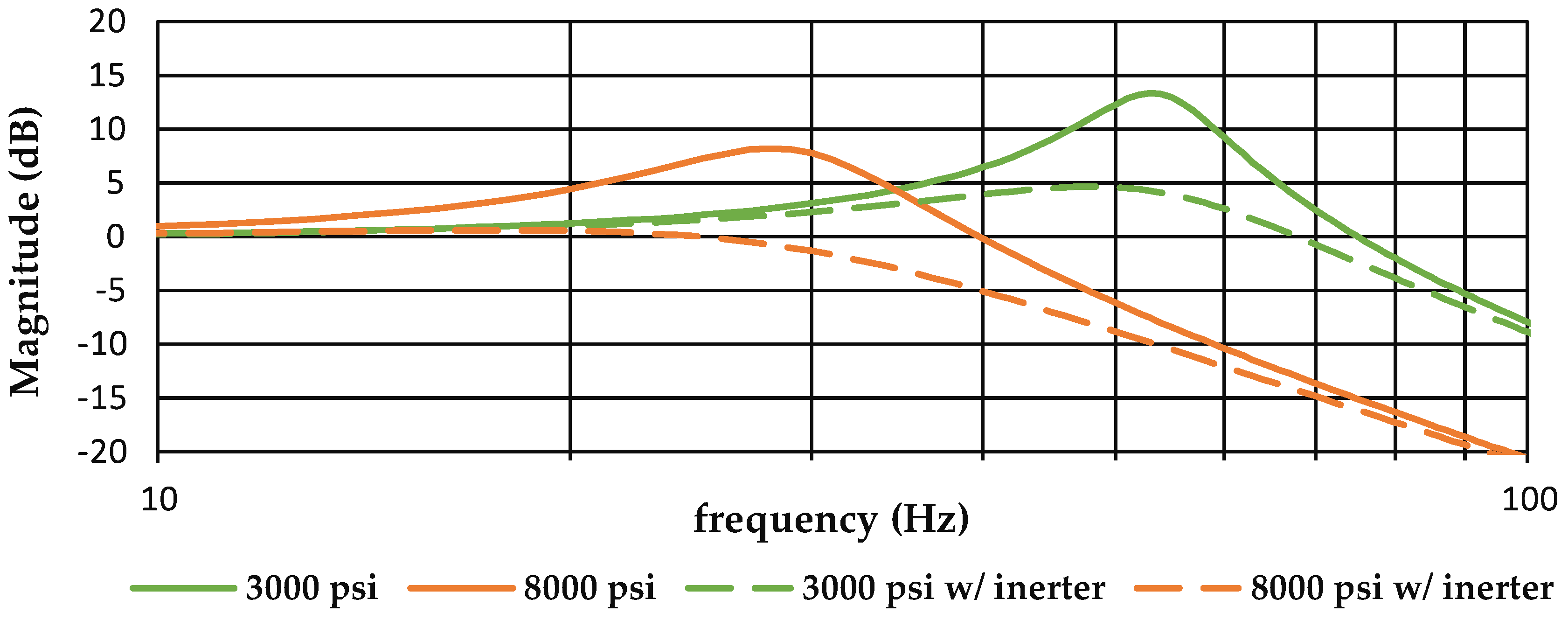
19].
Figure 4 shows improved damping of an actuator with an inerter sized for 55,144 kPa (8000 psi) system pressure and a damping factor of 1.0. The open-loop servo transfer function
is shown as Equation (3), and the damping factor for the rotational inerter and actuator as Equation (4):
where
is the viscous damping coefficient of the inerter disk in rotation in Equation (4),
is the actuator rod and load viscous damping coefficient,
is the linear hydraulic actuator stiffness with inerter,
is the inerter disk mass moment of inertia,
is the load inertia,
is the damping factor of the rotational inerter and actuator combination, and
is the ball screw thread rate of the inerter disk, which converts the translation of the actuator piston to the rotation of the inerter disk.
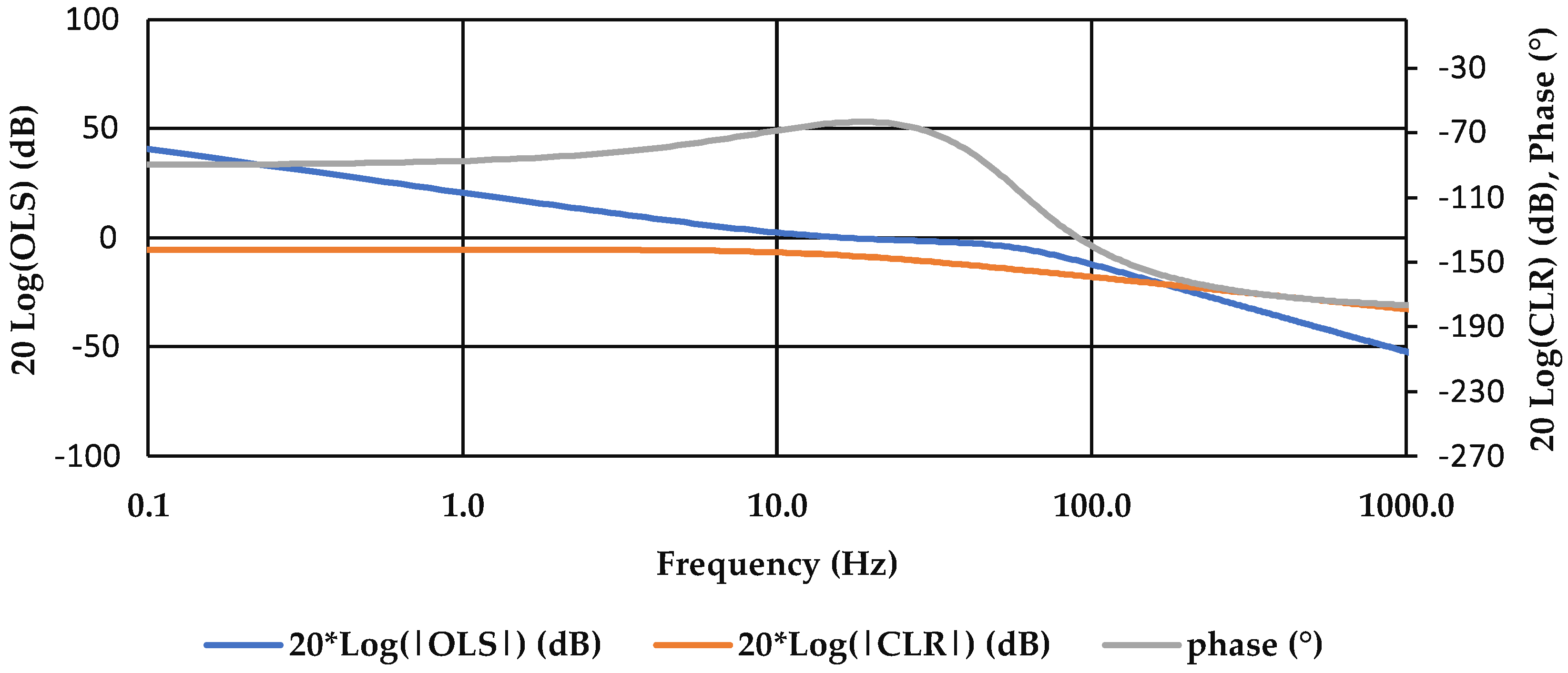
A lower system pressure of 55,144 kPa (8000 psi) is forced, producing the results of the third column of
Table 4 and
Figure 5, henceforth called solution 3. Peak power is reduced by 43% compared to solution 1, independent of the bandwidth reduction. The damping factor increased by 133% compared to solution 2. The system pressure of solution 3 is selected from prior research on optimal hydraulic system size, weight, and power [
20]. As stated, pressure is not a constrained variable in solutions 1 and 2, and actuator force is not computed in the model. Forcing a system pressure value did not change the displacement or control law gains compared to solution 2 and leaves one to conclude the same displacement is optimal for pressures between 55,144 kPa (8000 psi) and 96,500 kPa (14,000 psi) for this application. The dissipative loads are assumed to be met within this pressure range.
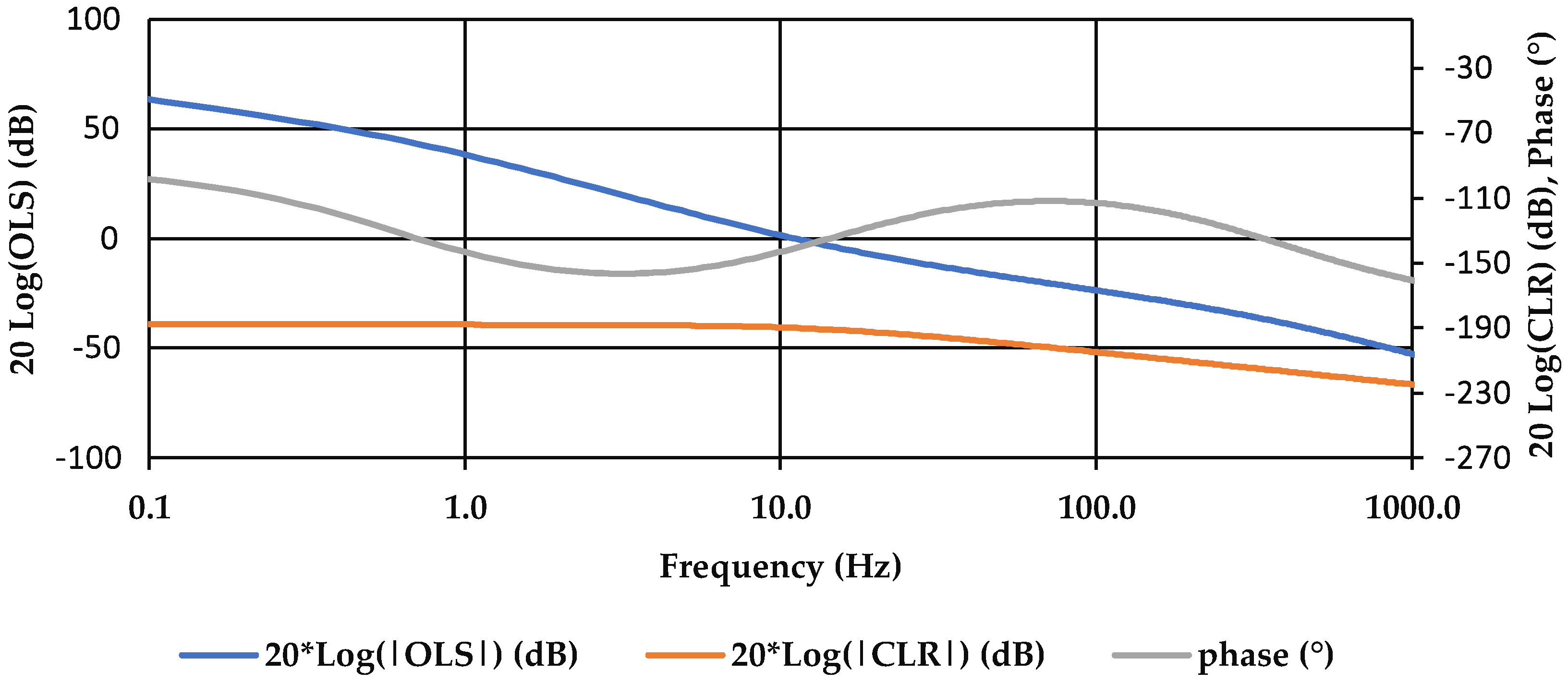
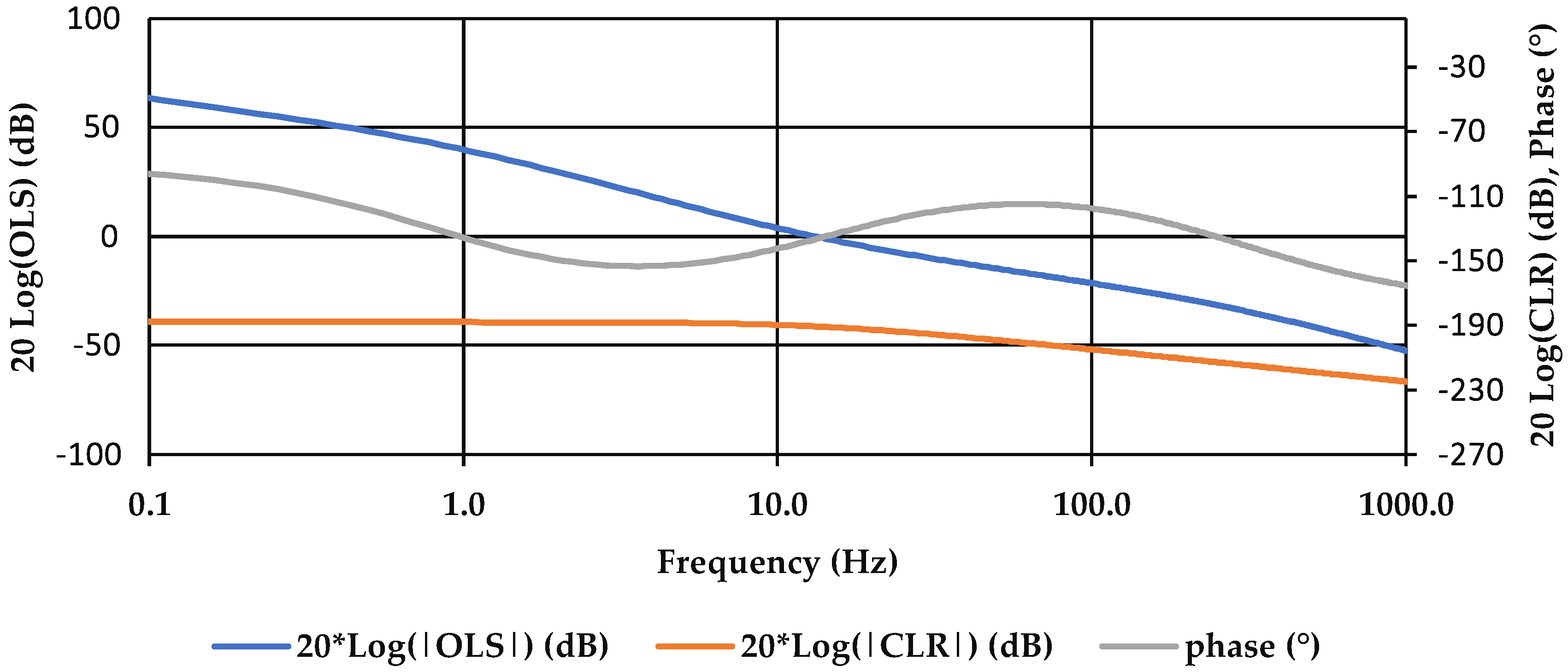
We can see from the frequency-response plot of
Figure 6 associated with solution 1 a marked lower amplitude at low frequencies of the OLS FTF. In contrast, the OLS FTF of solution 2 shown in
Figure 7, attains twice the amplitude at 1 Hz compared to solution 1. The CLR FTF attenuates to a lesser degree for solution 1, as shown in
Figure 6, compared to the CLR FTF for solution 2, as shown in
Figure 7.
4. Discussion
We find reduced linear stiffness once we relaxed the frequency–ratio constraint. Reduced stiffness is not feasible with typical axis damping. The frequency–ratio constraint value of 1.0 reflects a well-damped OLS FTF with the potential to set equal the crossover frequency and FNF. Once the designer finds a damping solution for the plant, the solution space may be expanded towards improved performance. The jitter performance estimate favors a smaller actuator, which operates at a higher pressure. The peak power for the constant pressure hydraulic system is not reduced with displacement when there is a requirement to increase the system pressure to achieve the same actuator-force capability. However, the stabilization problem we have selected places no constraint on force capability.
To the extent that solution 1 provides greater displacement than that required to drive the load at the required bandwidth, the system pressure does not have to scale with displacement, as shown in
Table 3. Because the bandwidth of solution 2 is less than that of solution 1, the maximum acceleration and force can be reduced in solution 2. At 2.6 Hz, the frequency response amplitude ratio is 0 dB for solution 1, while solution 2 includes an additional −40 dB/dec slope at that frequency compared to solution 1 and attenuation greater than −4.5 dB. An attenuation of −4.5 dB is a 65% power reduction. The system pressure associated with solution 3 is forced. Furthermore, solution 3 achieves an additional 15% lower OLS FTF crossover frequency compared to solution 2. This result is due to the reduced flow associated with reduced actuator displacement and reduced bandwidth.
We find that the improvement in jitter performance cannot be attributed to control-parameter selection with the relaxed frequency–ratio constraint in the last column of
Table 3 because the control-parameter values did not change. The performance is, therefore, a function of plant-parameter variation enabled by the relaxed frequency–ratio constraint. Control parameter SDO has an insufficient capability to improve system design PTE for this application. Typical control system design practice would have the designer increase the loop gain to match the phase margin and gain margin limits while unwittingly compromising PTE.


