Article

An Improved Extended State Observer-Based Composite Nonlinear Control for Permanent Magnet Synchronous Motor Speed Regulation Systems

1
School of Electrical Engineering, Southeast University, Nanjing 210096, China
2
Multidisciplinary Center for Infrastructure Engineering, Shenyang University of Technology, Shenyang 110870, China
3
School of Information and Control Engineering, China University of Mining and Technology, Xuzhou 221116, China
4
Institute of Automatic Control, Lodz University of Technology, 18 Stefanowskiego St., 90-537 Lodz, Poland
*
Author to whom correspondence should be addressed.
Energies 2022, 15(15), 5699; https://doi.org/10.3390/en15155699
Submission received: 16 July 2022 / Revised: 3 August 2022 / Accepted: 4 August 2022 / Published: 5 August 2022

Abstract

:
This paper addresses the problems of an improved extended state observer (ESO)-based composite nonlinear control for the permanent magnet synchronous motor (PMSM) speed regulation systems, which is primarily constituted by a linear ESO-based feedforward compensation and nonlinear proportional feedback (NPF) control law. Firstly, by taking the parametric perturbations and external disturbances into account, a novel linear ESO is designed and analyzed to estimate the lumped disturbance, such that the system anti-disturbance performance is preserved. Meanwhile, the estimation of system state is also performed. Then, an optimal control synthesis function-based tracking differentiator (TD) is developed to arrange the transition dynamic for the reference velocity value, while its high quality differential signal is facilitated. Furthermore, an adaptive proportional control law is proposed, resulting in the eventual composite nonlinear strategy by incorporating the estimate values into the designed NPF controller. Finally, a PMSM servo system is studied to demonstrate the advantages and effectiveness of the proposed approaches.

1. Introduction

With the development of power electronics and control theory, and the increasing demands of higher precision and higher performance existing in practical industrial applications [1], the speed regulation systems for permanent magnet synchronous motors (PMSMs) have been extensively receiving much more attention [2]. PMSMs are characterized by many excellent features such as high efficiency, high power/weight ratio, low noise, and maintenance-free capability [3]. Generally speaking, the field orientation control (FOC) methodology, namely the vector control approach, is recommended in a high-performance PMSM servo system [4]. Under this scheme, the torque- and flux-producing components of the stator current are completely decoupled and separately controlled, such that the PMSMs achieve similar performances as the DC motors [5]. It is well known that the mathematical model of a PMSM is a nonlinear, high-order, and strongly coupling multi-variable system [6]. At the same time, there usually exist friction force, external load disturbance, and internal parameter uncertainties/perturbations in the complex operation environments, which will severely deteriorate system dynamic performances [7]. To this end, the investigation of controller design for PMSMs has important significance.
Many researchers have devoted themselves to exploring innovative approaches for motion control systems (see [8,9,10,11,12,13,14,15,16] and the references therein). The classical linear control method, for example, the proportional–integral (PI) controller, is widely adopted and benefits from the gain parameters being easily determined and adjusted [8]. However, this method cannot provide a satisfactory performance. Consequently, many advanced nonlinear control technologies have been presented with the development of modern control theory, resulting in improved system robustness [9]. In [10], a two degree of freedom (DOF) robust H control method was adopted in a motor speed regulation system, where a disturbance observer feedforward compensation-based composite control structure was designed to improve the dynamic performance of the system. Based on statistical model interpretation, Ji et al. [11] proposed a robust model reference adaptive control (MRAC) strategy to solve the current loop adjustment problem for PMSMs. As a PMSM is usually influenced by external load torque and unmodeled dynamics during operation, an extended state observer (ESO) was designed to derive its estimated value, and the backstepping control algorithm was applied to the position tracking problem [12]. Active disturbance rejection control (ADRC) acts as a high-performance motor drive technology, and has been widely using in recent years [13]. The discrete-time repetitive controller was embedded in the designed ADRC [14], which was employed to compensate the AC disturbances and suppress the DC disturbances, respectively. Based on the conventional finite control set model predictive control (MPC), an improved MPC method for PMSM drive systems was presented in [15]. The gain parameters for controllers can be determined by setting different fuzzy logic membership functions [16], and thus improving the adaptive ability for PMSM speed regulation systems and the robustness against uncertainties. A novel reaching law-based sliding mode control (SMC) method was implemented in [17], where an extended sliding mode disturbance observer was also proposed to directly estimate the lumped uncertainties. It is worth mentioning that the abovementioned approaches have improved PMSM drive system performance in different aspects, and the observer feedforward compensation-based composite control strategy has become one of the most popularly used schemes for PMSM systems.
It should be emphasized that the disturbance observer (DO) is also an alternative and effective way to produce the estimation value of the external load torque (see [10,18,19,20] and the references therein). For example, the abovementioned H -based DO was presented as a feedforward compensation method [10]. A generalized proportional integral observer (GPIO) was firstly introduced to estimate the lumped disturbance in [18], and then the compensation estimation was incorporated into a super-twisting SMC law. For a PMSM servo drive system influenced by the lumped disturbance [19], a super-twisting sliding mode observer (SMO) was presented to estimate and compensate for the external disturbances, parametric uncertainties, unmodeled dynamics, etc. By eliminating the current control loop [20], an adaptive radial basis function (RBF)-based neural network observer was proposed to design the voltage control laws. However, the DO-based method involves the inverse dynamics of the controlled plant [2], which are highly dependent on the model information. Meanwhile, the upper bounds of the lumped disturbance and/or its differential are necessary to construct an available DO [21]. Therefore, in order to guarantee the convergence performance of the error estimation system, a conservative upper bound will usually be employed. Fortunately, the ESO considers the lumped disturbances as a new state variable, thus resulting in a feedforward compensation value for the designed feedback control law. The ESO can obtain accurate estimations regardless of the specific form and information of the lumped disturbances. As mentioned in [13], the ADRC technology is one of the most commonly used approaches in PMSM servo systems, while the conventional ADRC strategy mainly comprises a tracking differentiator (TD), the abovementioned ESO, and a state error feedback control law. It is worth mentioning that an appropriate TD can arrange a smoothly transitional reference signal for the PMSM speed regulation systems, thus improving the tracking performance. On the other hand, an additional DOF can be provided by employing the nonlinear combination [22], which will promote the system performance while maintaining the advantages of the synthesized linear controller. However, as mentioned in [13], most existing ADRC technologies have some drawbacks, mainly caused by difficult multi-parameter adjustments. Thus, the Fibonacci sequences are presented to determine the design parameters [23].
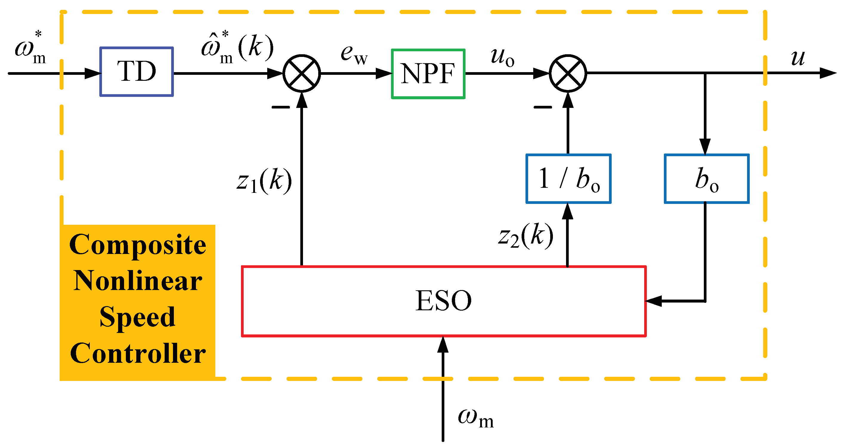
Motivated by the abovementioned discussions, this paper considers the problems of the composite nonlinear control for PMSM speed regulation systems with disturbances. By taking the parametric perturbations and external disturbances into account, a novel linear ESO is firstly designed and analyzed to estimate the lumped disturbance, such that the speed regulation system possesses strong anti-disturbance performance. Meanwhile, the estimation of system state is also performed. Then, an optimal control synthesis function-based TD is constructed, arranging the transition dynamic for the reference velocity value, while obtaining effective differential signals in noisy environments. Furthermore, the composite nonlinear scheme is synthesized by incorporating the ESO-based estimate values into nonlinear proportional feedback (NPF) control law. Finally, the advantages and effectiveness of the proposed methods are demonstrated by simulation results. The main contributions of this study can be summarized as follows. (1) The parametric perturbations and external disturbances characterized by lumped disturbance are fully taken into account during the construction of an improved linear ESO, which is free of the a priori disturbance information. In addition, although the nonlinear ESO with fal(·) function may be popularly employed as a feedforward compensation method [13], which suffers from the parameter determinations of ESO feedback gains by artificial experience of trial and error [22]. To this end, the presented linear ESO (in this study) is an alternative effective approach to obtain accurate estimate values. Furthermore, the strictly theoretical result is given to analyze the convergence domain, while providing the guidelines to choose the appropriate parameters by adopting the eigenvalue placement technique. (2) An optimal control synthesis function-based TD is employed, resulting in a favorable transition dynamic for the reference velocity value, while its high-quality differential signal is simultaneously obtained. (3) The composite nonlinear control law is synthesized by combining the ESO-based feedforward compensation and NPF feedback controller. Benefitting from the adaptive gain adjustment, the presented control strategy can guarantee satisfactory system performance with the strong robustness against the lumped disturbances. In addition, it should be emphasized that, here, only proportional action is involved to reduce the complexity of the control algorithm and the corresponding burden of parameter determinations.
The rest of this paper is organized as follows. In Section 2, system modeling and preliminaries are described. The main results are given in Section 3, including the design and analysis of the composite nonlinear control approach. Some simulation results are given in Section 4. Section 5 concludes this paper.

2. System Modeling and Preliminaries

The general dynamic model of a PMSM is given as follows [10], which can be established with respect to a two-phase synchronous rotating orthogonal d q reference coordinate system,
u d = R s i d + L d d d t i d ω e L q i q ,
u q = R s i q + L q d d t i q + ω e L d i d + ω e ψ f ,
T e = 3 2 p n i q i d L d L q + ψ f ,
J d d t ω m = T e T m F ω m ,
where u d and u q represent d and q axis stator voltages, respectively; R s is stator resistance; i d and i q denote d and q axis stator currents, respectively; L d and L q are d and q axis stator inductances, respectively; ψ f is the flux linkage of permanent magnets; T e is the electromagnetic torque; p n is the number of pole pairs; J is the moment of the rotational inertia; T m represents the load torque disturbance; F is the viscous friction coefficient; ω e and ω m are electrical and mechanical angular velocities, respectively, which satisfy ω e = p n ω m .
For simplicity, we consider surface-mounted PMSMs in this paper, which are characterized by L d = L q = L s . As a result, we can obtain the simplified mathematical model of a PMSM, comprising the following electrical dynamics:
L s d d t i d = u d R s i d + ω e L s i q L s d d t i q = u q R s i q ω e L s i d ω e ψ f ,
and mechanical dynamic equation
J d d t ω m = F ω m + K T i q T m ,
where K T = 3 p n ψ f 3 p n ψ f 2 2 is the electromagnetic torque coefficient.
The research objective of this study is to design a novel composite nonlinear controller for a PMSM speed regulation system, resulting in:
(1) The currents i d and i q should track their references i d * and i q * , respectively. That is to say,
i d i d * , i q i q * ,
where the d axis reference current i d * = 0 .
(2) The mechanical angular velocity ω m should be regulated to its reference velocity value ω m * in the presence of the lumped disturbance, namely,
ω m ω m * .
Remark 1.
According to the electrical dynamic Equation (5), it is possible to effectively control the currents with a PI controller. Motivated by the internal model control (IMC) theory [3], if the nonlinear cross-coupling back electromotive forces (EMFs) are eliminated for the nominal system, the transfer function will be equivalent to an inertia element with the electrical time constant. To this end, if a bandwidth of inner loop ω c is chosen, then the controller gains can be easily determined as K P = ω c L s and K I = ω c R s , respectively. In addition, it should be mentioned that the gradient descent-based adaptive parameter adjustment method was presented for the proportional integral derivative (PID) controller [8], and the resulting design scheme has been demonstrated to possess superior control performance.
In the following, we will primarily concentrate on the design and analysis of the outer loop controller in the conventional cascade scheme. If the approximation error between the i q * and the speed loop output is considered, then mechanical dynamic Equation (6) can be modeled as
d d t ω m = b o u + d ( t ) ,
where b o = K T K T J J is the system parameter for the eventual composite nonlinear control u = i q * ; f ( t ) = J d ( t ) = F ω m K T e q T m is the lumped disturbance that needs to be estimated by the subsequent designed ESO; e q = i q * i q is the q axis current error.

3. ESO and Composite Control Law Design

In this section, we will design the control law defining u based on the system (9), including the ESO, TD, NPF, and composite nonlinear control law.

3.1. ESO Design and Analysis

For the sake of compensating the adverse effect of disturbances on the system performances, a novel linear ESO is constructed for the system (9), namely,
d d t z 1 z 2 = 0 1 0 0 z 1 z 2 + b o 0 u 1 ε α 1 α 2 ε e z ,
where z 1 and z 2 are the accurate estimation values for the motor velocity ω m and the lumped disturbance d ( t ) , respectively; e z = e z ( k ) = z 1 ( k ) ω m is the estimation error; ε is a positive parameter associated with the convergence domain; α 1 > 0 and α 2 > 0 are the ESO feedback gains, whose values are proportional to the ESO estimation velocity.
For the proposed novel ESO (10), we have the following theorem.
Theorem 1.
The estimation error system of the linear ESO is asymptotically stable to a ε-dependent convergence domain. That is to say, the estimate states will approximate the corresponding actual values, respectively.
Proof. 
First of all, we can define the following estimation error variables:
ζ = ζ 1 ζ 2 = z 1 ω m ε z 2 d ( t ) .
The following equation can be easily obtained by combining (9)–(11):
d d t ζ 1 = 1 ε d d t z 1 d d t ω m = 1 ε α 1 e z ε + z 2 d ( t ) = 1 ε α 1 ζ 1 + ζ 2 .
Obeying the same procedure, substituting Equation (10) into Equation (11) leads to the following formulation:
d d t ζ 2 = d d t z 2 d d t d ( t ) = α 2 ε 2 e z d ˙ ( t ) = 1 ε α 2 ζ 1 ε d ˙ ( t ) .
Thus, the estimation error system can be easily obtained from (11)–(13), namely,
ε ζ ˙ = α 1 1 α 2 0 ζ + ε 0 1 d ˙ ( t ) = A o ζ + ε B o d ˙ ( t ) .
Therefore, the characteristic polynomial of the above system matrix A o is calculated as
λ I A o = λ + α 1 1 α 2 λ = λ 2 + α 1 λ + α 2 ,
where I is an identity matrix, and λ represents the eigenvalue.
In order to realize the convergence of the estimation error system (14), we can appropriately determine the parameters α 1 and α 2 , such that the real part of the eigenvalues is negative. To this end, the abovementioned A o will become a Hurwitz matrix. According to the well-known modern control theory, there exists a positive definite matrix P R 2 × 2 satisfying the following Lyapunov equation for any given Q R 2 × 2 > 0 :
A o T P + P A o = Q .
Defining the Lyapunov candidate function as the following quadratic form:
V o = ε ζ T P ζ .
Taking the time-derivative of the V o with respect to ζ yields
V ˙ o = ε ζ ˙ T P ζ + ζ T P ε ζ ˙ = A o ζ + ε B o d ˙ ( t ) T P ζ + ζ T P A o ζ + ε B o d ˙ ( t ) = ζ T A o T P + P A o ζ + 2 ε ζ T P B o d ˙ ( t ) ζ T Q ζ + 2 ε ζ · P B o · d ˙ ( t ) λ min ( Q ) ζ 2 + 2 ε M ζ · P B o ,
where λ min ( Q ) > 0 is the minimum eigenvalue of the matrix Q ; · denotes the Euclidean norm; d ˙ ( t ) M , and M is the differential upper bound of lumped disturbances d ( t ) .
The following convergence domain can be obtained from the above inequality (18):
ζ ε 2 M P B o λ min ( Q ) ,
which indicates that the estimation error variables ζ 1 and ζ 2 are directly proportional to parameter ε . Therefore, a smaller ε is recommended to improve the estimation precision.
This completes the proof. □
In summary, the discrete-time form of the ESO (10) can be derived as follows.
1 T s z 1 ( k + 1 ) z 1 ( k ) z 2 ( k + 1 ) z 2 ( k ) = 0 1 0 0 z 1 ( k ) z 2 ( k ) + b o 0 u 1 ε α 1 α 2 ε e z ,
where T s is the discrete step; k and k + 1 represent the current and next instants, respectively.
Remark 2.
The developed high-precision linear ESO (20) estimates the system state and lumped disturbance, simultaneously. It should be emphasized that for the situations where it may difficult to obtain the accurate disturbance information or there are no corresponding measurement transducers, the designed ESO can realize the accurate estimations, only relying on the control law u and the measurement signal ω m , regardless of the specific form and information of the disturbances. This is an obvious advantage compared with other observers, for example, the DO presented in [21]. As a result, active suppression of a disturbance can be realized, by incorporating its estimate value provided by the ESO into the subsequent feedback controller.

3.2. TD-Based NPF Design

As mentioned in [22], the control system performance is significantly constrained by the differential signal, where a high-order controlled plant will usually be considered. The conventional backward difference (BD)-based extraction method will unavoidably amplify the measurement noise and introduce an additional delay, which is caused by filtering the differential signal.
At the same time, the initial tracking error between reference velocity value and the motor feedback velocity signal (increases from zero) is relatively large, which needs a strong control effort to accelerate the tracking response. However, a large overshoot will inevitably appear before the PMSMs operate the steady state. To this end, in order to improve the tracking performance, it is necessary to smooth the reference velocity value, which is probably set as a step signal. To these ends, an optimal control synthesis function-based TD is developed in this section, which is aimed at arranging the transition dynamic, while its high-quality differential signal is feasible. For the following continuous system:
x ˙ 1 x ˙ 2 = x 2 u r ,
where u r r , and r is the speed factor.
An optimal control synthesis function is introduced for its discrete-time system, yielding the following nonlinear TD:
x ^ 1 ( k + 1 ) x ^ 1 ( k ) x ^ 2 ( k + 1 ) x ^ 2 ( k ) = T s x ^ 2 ( k ) fhan e ( k ) , x ^ 2 ( k ) , r , h ,
where x ^ 1 and x ^ 2 are the real-time tracking estimation signals for x 1 and its differential value x 2 , respectively; e ( k ) = x ^ 1 ( k ) x 1 ( k ) is the TD tracking error; h is the filtering factor [23].
The optimal control synthesis function u r = fhan ( · ) is defined as
d = r h , d o = h d y = e ( k ) + h x ^ 2 ( k ) a o = d 2 + 8 r y a = x ^ 2 ( k ) + a o d 2 sgn ( y ) , y > d o x ^ 2 ( k ) + y h , y d o fhan e ( k ) , x ^ 2 ( k ) , r , h = r sgn ( a ) , a > d r a d , a d ,
where sgn ( · ) denotes the sign function.
Remark 3.
The presented high-performance TD (22) has strong robustness against the parameter perturbations of r and h. A large value of the speed factor r will accelerate the transition tracking dynamic with a bigger acceleration amplitude, which can be demonstrated by the later simulation results. At the same time, a smaller discrete step T s is recommended for suppression noise amplification, while decreasing the approximation difference between the continuous system and its discrete form. In addition, the filtering factor h should be greater than the value of T s , which determines the noise attenuation characteristic, and there is a tradeoff between the tracking and filtering performances.
It is well known that a linear PI controller can achieve a compromised performance in terms of system response speed and overshoot [23]. Fortunately, the nonlinear combination of the tracking error is an alternative way to improve the system performance, while maintaining the advantages of simplicity and feasibility of the linear PI control strategy. To this end, an NPF control law can be designed as follows:
u o = K PS e w = K S fal ( e w , α w ) ,
where e w = e w ( k ) = ω ^ m * ( k ) z 1 ( k ) is the velocity tracking error, and ω ^ m * = ω ^ m * ( k ) is the estimation signal obtained from TD (22) for the reference velocity value ω m * .
The nonlinear function fal ( · ) is defined as
fal ( e w , α w ) = e w α w sgn ( e w ) , e w > 0.01 0.01 α w 1 e w , e w 0.01 ,
where α w > 1 is the parameter to be selected later.
According to Formula (24), we can obtain the relationship between the adaptive parameter K PS and proportional gain K S , namely,
K PS = K S fal ( e n , α n ) e n .
Remark 4.
It is worth mentioning that the abovementioned designs of the TD, ESO, and NPF are directly designed in the discrete-time domain, which promote feasibility and realizability of the proposed approach for actual industrial applications. It is also worth mentioning that the digital implementation may be severely influenced by environmental noises, disturbances, communication/processing delays, sampling frequencies, etc. [24], which should be fully taken into account to improve the control performance. In particular, the sampling time is closely related to the system performance [25], which is limited by the associated hardware equipment. Therefore, the abovementioned practical factors (including the interrupt execution period) will be considered to motivate our future work.
As a result, the eventual composite nonlinear control action can be synthesized by incorporating the lumped disturbance estimate value z 2 ( k ) into the designed NPF (24), yielding
u = u o z 2 ( k ) b o .
The corresponding schematic block diagram of the composite nonlinear speed controller is shown as Figure 1. As mentioned in [5], the general control scheme of a PMSM servo drive system basically employs a cascade structure, which includes a speed loop (usually adopting the PI controller) and two current loops. In this study, our research objective mainly concentrates on the design of the speed controller. In Figure 1, the commonly used step-type reference velocity value ω m * is firstly smoothed by the presented TD (22), resulting in a favorable transition dynamic signal ω ^ m * . Meanwhile, the developed linear ESO (20) can obtain accurate estimations, only dependent on the control input u and the feedback velocity ω m , where its estimate value z 1 ( k ) and the lumped disturbance estimation compensation signal z 2 ( k ) are real-time derived, simultaneously. By combining the ESO-based feedforward compensation and the velocity tracking error e w -based NPF feedback controller u o , the composite nonlinear speed control law is eventually synthesized, replacing the PI speed regulator in the conventional vector control structure.
In addition, the overall control block diagram for a PMSM regulation system is shown as Figure 2. According to the reference velocity value ω m * and the actual feedback velocity ω m , the eventual composite nonlinear speed controller (27) generates the q axis reference signal u = i q * , while the corresponding d axis reference current is set as i d * = 0 . At the same time, based on the well-known Clark and Park transformations ( θ e is the spatial angle of rotor flux linkage vector), the d and q axis currents i d and i q can be easily calculated from three-phase symmetrical currents i A , i B , and i C by incorporating the d and q axis stator current errors into the PI-type inner current controllers, respectively. Then, the control signals u d and u q are separately generated to improve the current tracking performance, which are subsequently used to produce the modulation waves u α and u β (through the Park inverse transformation) for the space vector pulse width modulation (SVPWM) component. Finally, the corresponding pulse signals are transmitted to the voltage source inverter, generating the three-phase voltages for the PMSMs. To this end, the closed-loop control of the servo drive system is realized by adopting the presented approach.

4. Simulation Results

In this section, a PMSM is studied to demonstrate the effectiveness and advantages of the proposed approach, whose specification parameters are listed in Table 1.
In addition, the DC-link capacitor voltage for the three-phase inverter and the pulse width modulation (PWM) frequency are set as U dc = U n × 2 V and f PWM = 10 kHz , respectively. For the current control loop, once the bandwidth ω c = 4 × 10 3 Hz is chosen, the controller gains can be easily obtained as Remark 1. That is to say, K P = ω c L s = 4 × 10 3 × 4.492 × 10 3 = 17.968 and K I = ω c R s = 4 × 10 3 × 0.454 = 1.816 × 10 3 , respectively, where the current output saturation magnitude values are selected as ± 0.9 × U n . Meanwhile, the design parameters of the composite nonlinear speed controller are listed in Table 2. In addition, the speed output saturation magnitude values are selected as ± 0.9 × I n . It should be emphasized that we built the overall control block diagram in Figure 2 and carried it out based on Remark 1, where the d and q axis back EMFs are ignored. It is recommended to develop the EMF compensation method, such that the whole system performance will be further improved.
It is worth mentioning that when the ESO gain parameters are selected as in Table 2, the characteristic polynomial (15) can be easily calculated as λ 2 + α 1 λ + α 2 = λ + 1 2 , which results in Re( λ ) < 0. According to the classical automatic control principle, a large-amplitude real part of the eigenvalue will accelerate the estimation convergence velocity. On the other hand, if we set the matrix as Q = I for the presented Theorem 1, and by solving the corresponding Lyapunov Equation (16), the following positive definite matrix can be obtained:
P = 0 . 5 0 . 5 0 . 5 1 . 5 ,
where its eigenvalues are 0.2929 and 1.7071, respectively. As a result, the stability condition is guaranteed. Meanwhile, a rough differential upper bound M-based convergence domain (19) will be subsequently derived.
Firstly, when we select the proportional gain as K S = 5 × 10 3 , the evolutions of nonlinear function fal ( e n , α n ) and adaptive parameter K PS with proportional gain K S are as shown in Figure 3.
From Figure 3, it can be seen that the function fal ( e w , α w ) is smooth with respect to the velocity tracking error e w , which is assumed to linearly range from 3 rad / s to 3 rad / s . In addition, when the e w is relatively large, the enlarged proportional parameter K PS can generate a great correction to improve the tracking performance. On the contrary, a decreasing K PS emerges to reduce the overshoot as the error diminishes. Benefitting from the adaptive gain adjustment, the presented NPF exhibits rapid transient response while possessing small overshoot characteristics.
In order to demonstrate the effectiveness of the presented methods, we set the reference velocity value ω m * as a step signal, which changes from 30 rad/s to 80 rad/s at 0.2 s. When the different values of velocity factor r are determined, the output signals of the presented TD (22) are as shown in Figure 4. It can be concluded from Figure 4 that a large speed factor will accelerate the transition tracking dynamic, while a bigger acceleration amplitude will be produced.
Meanwhile, when the specific values listed in Table 2 are selected to perform the presented method, the velocity estimation ω ^ m * together with its differential signal ω ˙ ^ m * are as shown in Figure 5, which reveal that the proposed TD (22) can arrange a favorable transition dynamic, while its high-quality differential signal has the perfect noise-filtering performance.
Under the NPF-based composite nonlinear speed controller, and the zero initial conditions for all state variables, the velocity response ω m and its corresponding ESO-based estimation value z 1 ( k ) are as shown in Figure 6.
In order to illustrate the speed regulation system robustness against the lumped disturbance d ( t ) , and analyze the ESO-based estimation characteristic, an external load torque T m with step disturbance that suddenly varies from 2 N·m to 5 N·m at 0.4 s is employed. Meanwhile, for the sake of exploring the steady-state estimation performance, a low-pass filter (LPF) with the cutoff frequency set as 60 Hz is adopted to filter the high-order harmonics existing in e q . As a result, the lumped disturbance f ( t ) with the designed ESO-based estimate signal J z 2 ( k ) is as shown in Figure 7.
It can be concluded from Figure 6 and Figure 7 that the presented ESO (20) can precisely estimate the system state and lumped disturbance, simultaneously. In addition, benefitting from the adaptive parameter adjustment of NPF (24) and the active feedforward compensation, the velocity tracking performance is characterized by short response times, small overshoot and steady-state error, etc. Meanwhile, by comparing Figure 5 with Figure 6, it can be summarized that the PMSM regulation system under the eventual composite nonlinear speed controller (27) has strong robustness to the lumped disturbances, where the velocity fluctuations are within ± 0.4 rad/s. In [5], the speed fluctuation index and recovery time were introduced, for which the best existing results can be listed as follows: the smallest speed decrease and fluctuation were 9 rpm and 3.875 rpm, respectively. By considering the operation speed (1000 rpm), the corresponding percentages can be easily calculated as 0.9% and 0.3875%, respectively. To this end, we define an error as e * = ω m * ω m for the PMSM speed regulation, and its evolution curve is shown as Figure 8. It can be concluded from Figure 8 that the motor velocity ω m can rapidly converge its reference signal ω m * and quickly recover to the steady state in the presence of suddenly varied disturbance. It should be emphasized that the velocity fluctuation percentage is less than 0.2%. In addition, the biggest velocity decrease is about 0.4 rad/s, which results in a corresponding percentage of 0.5%. In summary, the velocity decrease and fluctuation percentages of the presented method are all less than existing results.

5. Conclusions

This paper has investigated the problem of the composite nonlinear control for PMSM speed regulation systems with disturbances. An improved ESO-based feedforward disturbance compensation, an optimal control synthesis function-based TD, and an adaptive NPF approach have been presented in detail. By virtue of the eventually synthesized speed controller, the obtained ESO can precisely estimate the system state and lumped disturbance, simultaneously. In addition, the closed-loop PMSM regulation system possesses strong anti-disturbance performance, while the velocity tracking performance has short response times and small overshoot and steady-state error. Our future work will concentrate on the design and analysis of a digital implementation, which involves environmental noises, disturbances, communication/processing delays, sampling frequencies/time, interrupted execution period, etc.

Author Contributions

This is a joint work and the authors were in charge of their expertise and capability: Z.C. for investigation and analysis; H.Y. for validation and revision; S.M. for methodology; M.A. for writing and revision; C.Y. for manuscript revision; A.B. for data analysis. All authors have read and agreed to the published version of the manuscript.

Funding

This work was supported by the National Natural Science Foundation of China under Grant 41576096, 42176211, Fundamental Research Funds for the Central Universities under Grant 3216002104D, and Postgraduate Research & Practice Innovation Program of Jiangsu Province under Grant SJCX20_0013.

Acknowledgments

The authors would like to express their gratitude to all those who helped them during the writing of this paper. The authors would like to thank the reviewers for their valuable comments and suggestions.

Conflicts of Interest

The authors declare no conflict of interest.

References

  1. Wu, J.; Qin, L.; Chen, N.; Qian, C.; Zheng, S. Investigation on a Spring-Integrated Mechanical Power Take-Off System for Wave Energy Conversion Purpose. Energy 2022, 245, 123318. [Google Scholar] [CrossRef]
  2. Yang, J.; Chen, W.H.; Li, S.; Guo, L.; Yan, Y. Disturbance/Uncertainty Estimation and Attenuation Techniques in PMSM Drives—A Survey. IEEE Trans. Ind. Electron. 2017, 64, 3273–3285. [Google Scholar] [CrossRef] [Green Version]
  3. Mohamed, Y.A.R.I.; Saadany, E.F.E. A Current Control Scheme with an Adaptive Internal Model for Torque Ripple Minimization and Robust Current Regulation in PMSM Drive Systems. IEEE Trans. Energy Convers. 2008, 23, 92–100. [Google Scholar] [CrossRef]
  4. Wang, Y.; Yu, H.T.; Liu, Y.L. Speed-Current Single-Loop Control with Overcurrent Protection for PMSM Based on Time-Varying Nonlinear Disturbance Observer. IEEE Trans. Ind. Electron. 2022, 69, 179–189. [Google Scholar] [CrossRef]
  5. Li, S.H.; Zong, K.; Liu, H.X. A Composite Speed Controller Based on a Second-Order Model of Permanent Magnet Synchronous Motor System. Trans. Inst. Meas. Control 2011, 33, 522–541. [Google Scholar]
  6. Yang, C.Y.; Che, Z.Y.; Zhou, L.N. Composite Feedforward Compensation for Force Ripple in Permanent Magnet Linear Synchronous Motors. J. Shanghai Jiaotong Univ. Sci. 2019, 24, 782–788. [Google Scholar] [CrossRef]
  7. Mobayen, S.; Mostafavi, S.; Fekih, A. Non-Singular Fast Terminal Sliding Mode Control with Disturbance Observer for Underactuated Robotic Manipulators. IEEE Access 2020, 8, 198067–198077. [Google Scholar] [CrossRef]
  8. Jung, J.W.; Leu, V.Q.; Do, T.D.; Kim, E.K.; Choi, H.H. Adaptive PID Speed Control Design for Permanent Magnet Synchronous Motor Drives. IEEE Trans. Power Electron. 2015, 30, 900–908. [Google Scholar] [CrossRef]
  9. Che, Z.; Yu, H.; Yang, C.; Zhou, L. Passivity Analysis and Disturbance Observer-Based Adaptive Integral Sliding Mode Control for Uncertain Singularly Perturbed Systems with Input Nonlinearity. IET Control. Theory Appl. 2019, 13, 3174–3183. [Google Scholar] [CrossRef]
  10. Li, L.; Pei, G.; Liu, J.; Du, P.; Pei, L.; Zhong, C. 2-DOF robust H Control for Permanent Magnet Synchronous Motor with Disturbance Observer. IEEE Trans. Power Electron. 2021, 36, 3462–3472. [Google Scholar] [CrossRef]
  11. Jin, H.Z.; Lee, J.M. An RMRAC Current Regulator for Permanent-Magnet Synchronous Motor Based on Statistical Model Interpretation. IEEE Trans. Ind. Electron. 2009, 56, 169–177. [Google Scholar]
  12. Linares-Flores, J.; García-Rodríguez, C.; Sira-Ramírez, H.; Ramírez-Cárdenas, O.D. Robust Backstepping Tracking Controller for Low-Speed PMSM positioning System: Design, Analysis, and Implementation. IEEE Trans. Ind. Inform. 2015, 11, 1130–1141. [Google Scholar] [CrossRef]
  13. Lu, W.; Li, Q.; Lu, K.; Lu, Y.; Guo, L.; Yan, W.; Xu, F. Load adaptive PMSM Drive System Based on an Improved ADRC for Manipulator Joint. IEEE Access 2021, 9, 33369–33384. [Google Scholar] [CrossRef]
  14. Tian, M.; Wang, B.; Yu, Y.; Dong, Q.; Xu, D. Discrete-Time Repetitive Control-Based ADRC for Current Loop Disturbances Suppression of PMSM Drives. IEEE Trans. Ind. Inform. 2022, 18, 3138–3149. [Google Scholar] [CrossRef]
  15. Zhang, X.G.; Bai, H.L.; Cheng, M. Improved Model Predictive Current Control with Series Structure for PMSM Drives. IEEE Trans. Ind. Electron. 2022, 69, 12437–12446. [Google Scholar] [CrossRef]
  16. Chaoui, H.; Khayamy, M.; Aljarboua, A.A. Adaptive Interval Type-2 Fuzzy Logic Control for PMSM Drives with a Modified Reference Frame. IEEE Trans. Ind. Electron. 2017, 64, 3786–3797. [Google Scholar] [CrossRef]
  17. Zhang, X.; Sun, L.; Zhao, K.; Sun, L. Nonlinear Speed Control for PMSM System Using Sliding-Mode Control and Disturbance Compensation Technique. IEEE Trans. Power Electron. 2013, 28, 1358–1365. [Google Scholar] [CrossRef]
  18. Hou, Q.K.; Ding, S.H. GPIO Based Super-Twisting Sliding Mode Control for PMSM. IEEE Trans. Circuits Syst. II Express Briefs 2021, 68, 747–751. [Google Scholar] [CrossRef]
  19. Liu, Y.C.; Laghrouche, S.; Depernet, D.; Djerdir, A.; Cirrincione, M. Disturbance-Observer-Based Complementary Sliding-Mode Speed Control for PMSM Drives: A Super-Twisting Sliding-Mode Observer-Based Approach. IEEE J. Emerg. Sel. Top. Power Electron. 2021, 9, 5416–5428. [Google Scholar] [CrossRef]
  20. Chaoui, H.; Khayamy, M.; Okoye, O. Adaptive RBF Network Based Direct Voltage Control for Interior PMSM Based Vehicles. IEEE Trans. Veh. Technol. 2018, 67, 5740–5749. [Google Scholar] [CrossRef]
  21. Yang, C.Y.; Che, Z.Y.; Zhou, L.N. Integral Sliding Mode Control for Singularly Perturbed Systems with Mismatched Disturbances. Circuits Syst. Signal Process. 2019, 38, 1561–1582. [Google Scholar] [CrossRef]
  22. Su, Y.X.; Zheng, C.H.; Duan, B.Y. Automatic Disturbances Rejection Controller for Precise Motion Control of Permanent-Magnet Synchronous Motors. IEEE Trans. Ind. Electron. 2005, 52, 814–823. [Google Scholar] [CrossRef]
  23. Han, J.Q. Active Disturbance Rejection Control Technique; National Defense Industry Press: Arlington, VA, USA, 2008. [Google Scholar]
  24. Mohammadzahei, M.; Ziaiefar, H.; Ghodsi, M.; Bahadur, I.B. Yaw Control of an Unmanned Helicopter with Feedback Linearization. In Proceedings of the First International Conference on Unmanned Vehicle Systems-Oman (UVS), Muscat, Oman, 5–7 February 2019. [Google Scholar]
  25. Mohammadzahei, M.; Chen, L. Intelligent Predictive Control of a Model Helicopter’s Yaw Angle. Asian J. Control 2010, 12, 667–679. [Google Scholar] [CrossRef]
Figure 1. The composite nonlinear speed controller.
Energies 15 05699 g001
Figure 2. The overall control block diagram for a PMSM regulation system.
Energies 15 05699 g002
Figure 3. The characteristic curves of fal ( e w , α w ) and K PS .
Energies 15 05699 g003
Figure 4. The output signals of presented TD with r = 7 × 10 3 and r = 7 × 10 5 .
Energies 15 05699 g004
Figure 5. The reference velocity value ω m * with its corresponding estimation values.
Energies 15 05699 g005
Figure 6. The velocity response ω m and its ESO-based estimation value.
Energies 15 05699 g006
Figure 7. The lumped disturbance f ( t ) with the designed ESO-based estimate signal.
Energies 15 05699 g007
Figure 8. The evolution curve of the error e.
Energies 15 05699 g008
Table 1. Specification parameters of a PMSM.
SymbolValueUnit
R s 0.454 Ω
L s 4.492 mH
ψ f 0.1435Wb
I n (rated current)13.5A
U n (rated voltage)220V
J 2.77 × 10 3 kg · m 2
F 3.79 × 10 3
p n 4
Table 2. Design parameters of the composite nonlinear speed controller.
T s hr α 1 α 2 ε α w
2 × 10 7 10 × T s 5 × 10 4 21 0.5 × 10 3 1.5
Publisher’s Note: MDPI stays neutral with regard to jurisdictional claims in published maps and institutional affiliations.

