Article

Novel Magnetic Suspension Platform with Three Types of Magnetic Bearings for Mass Transfer

1
Institute of Precision Electromagnetic Equipment and Advanced Measurement Technology, Beijing Institute of Petrochemical Technology, Beijing 102617, China
2
School of Mechanical Engineering, TianGong University, TianJin 300387, China
*
Author to whom correspondence should be addressed.
Energies 2022, 15(15), 5691; https://doi.org/10.3390/en15155691
Submission received: 31 May 2022 / Revised: 23 July 2022 / Accepted: 1 August 2022 / Published: 5 August 2022

Abstract

:
For ultra-precision, large stroke, and high start/stop acceleration, a novel magnetic suspension platform with three types of magnetic bearings is proposed. The structure and working principle of the novel platform are introduced. The passive magnetic bearings are used to compensate for the weight of the actuator. The repulsive force of the passive magnetic bearing model is established and analyzed. The Lorentz force-type magnetic bearings are used to provide driving force and rotational torque in the XY-plane. The driving force model and rotational torque model are established. The electromagnetic suspension bearing is used to provide driving force in the Z-axis and rotational torque along the X-axis and Y-axis. A novel Halbach magnetic array is designed to improve the magnetic flux density in the air gap. The finite element method is used to validate the force model, torque model, and magnetic flux density in the air gap. The results show that the maximum force of the passive magnetic bearing is 79 N, and the rotational torque stiffness is 35 N/A in the XY-plane and 78 N/A along the Z-axis. The driving force stiffness is 91 N/A in the XY-plane and 45 N/A along Z-axis.

1. Introduction

Precision planar motion platforms are widely employed in pick and place machines, semiconductor manufacturing systems, transport devices, and scanning probe measurement systems [1,2,3,4]. Magnetic suspension platforms are widely used in the precision planar motion platforms as they have the advantages of noncontact, simple control, automatic stability, high positioning accuracy, and low noise. They have received more and more attention in recent years.
Kim invented the first magnetic suspension platform in [5]. The suspension and translation are provided by a linear motor. The suspension motion and translation motion are coupled as a linear motor and used at the same time. The Halbach magnetic array is used in the actuator. The stroke of the platform is 50 mm × 50 mm. The acceleration can reach 1 g. This platform can be used in the semiconductor manufacturing for photolithography. Subsequently, many scholars began to design and analyze magnetic suspension platforms with different stroke and functions. To isolate the ambient acceleration environment, Whorton designed a sub-track-level isolation platform in [6]. It can be used in a variety of applications. A g-LTMIT, consisting of three integrated isolator modules, is used to accomplish the six independent control actuation channels. The two axes of the control are uncoupled using different control actuation. A maglev linear actuator with nano-positioning capability is proposed by Kim in [7]. It has a lightweight and compact size as a novel configuration is used. The stroke is ± 500 μm with nanoscale positioning resolution. This platform can be used to verify the underlying theory and fundamental working principles. Sang [8] invented a multi-degree magnetic suspension platform. Large linear motion can be realized. The operating principle, magnetic force, and equation of motion are analyzed. The experiment shows that the platform can be used in industrial production. Bhat N and Kim invented a triangular magnetic suspension platform in [9]. A triangular is used in the actuator. The maximum velocity is 0.4 m/s with 2 m/s2 acceleration. The position resolution is 30 nm with a feedback controller. To improve the position resolution, a Y-shape magnetic suspension platform is proposed in [10]. The stroke is only ± 5 mm, and the position resolution is 3 nm. The structure is simple as only three permanent magnetics are used in the stator. Estevez, P manufactured a six-DOF miniature maglev positioning in [11]. A two-axis actuator is introduced. The actuator is driven by Lorentz forces. Three of the same actuators are used to provide six forces required in the stage. The stroke of the platform is 200 × 200 × 200 μm and the rotation is 18–42 mrad. The short stroke limits the use in the large stroke position. In [12], Zhang Z proposed a magnetic suspension platform with a two-axis linear actuator. The platform stroke is 2 × 2 × 2 mm in planer motion and 4° × × 4° in out-planer motion. The platform is very compact, and three compact two-axis linear actuators and six power amplifiers were used in the platform. The precision resolution is 1.1 nm for the X-axis and 4.4 nm for the Z-axis. Lee, D.J designed a three-DOF magnetic suspension platform with a surface motor-driven planar motion in [13]. The position accuracy and moving speed are improved. The platform’s precision positioning can be carried out independently in X, Y, and θ z with resolutions of 200 nm and 1″ using the angle sensor. The stroke is 40 mm in the X and Y directions. The drawback of the platform is that it has only three degrees of freedom, which cannot meet some applications with high requirements for degrees of freedom. To improve the degrees of freedom, Chen proposed a planar magnetic suspension platform with dual-axis in [14]. By involving magnetic forces, the platform is capable of cutting dual-axis planar motions purely. The model of the platform is derived and analyzed. The ASMC is used to guarantee the satisfactory performance. To achieve linear control of the platform drive force, Xu F invented a platform with a single-axis Lorentz force actuator in [15]. The controller is linear because of the use of Lorentz law. The stroke is 2 × 2 × 2 mm in translation and 80 × 80 × 40 mrad in rotation. The resolution of the translation is 2.8 μm. In [16], Yang F invented a improved Halbach magnetic array to improve the driving force and resolution. However, stroke is only 2 mm in the three-axis case. The platform is only used to isolate vibrations. In [17], the vertical and horizontal driving forces were produced by two sets of circuit board conductors perpendicular to each other in the same permanent magnetic field. As the effective length of the conducting wires is short, the platform’s stroke is short and the force is low. Zhang H used a novel magnetic levitation gravity compensator to improve the force performance and decrease the power consumption in [18]. With the novel gravity compensator, the platform has a large stroke in the Z-axis, but short stroke in the XY-plane. Takahashi invented a compact maglev stage system for nanometer-scale positioning in [19]. The compact feature was enabled by our newly proposed gravity compensation system with repellent force and a planar motor structure. As the gravity compensation system is used, the top-table mass of the motor was decreased and lightweight and high responsiveness characteristics were realized. Prosen [20] designed a magnetic flux density measurement platform with an inductive wireless power transmitter coil design. The platform can be used to measure the magnetic flux density, and a three-axis search coil is used. The platform is electromagnetically suspended and has strong nonlinearity. Li Z and Li B [21,22] analyzed the effect of different magnet arrangements on platform stroke. The results shows that the Halbach array can improve the magnetic flux density, but decrease the stroke of the platform. A novel Halbach array is needed to improve the stroke.
All of the platforms in the reference above have a short stroke. To improve the stroke of the magnetic suspension platform, Choi Y designed a high-precision dual-servo stage with a magnetically levitated fine stage in [23]. The Halbach linear active magnetic bearing is used, which can be used for gravity compensation and active control of vertical motion. The platform has two stages. The coarse stage’s stroke is 300 mm, and the fine stage’s stroke is ± 5 nm. A small-scale laboratory system was used to improve the stroke and develop technology required for the magnetic suspension of objects over large ranges of orientation in [24]. The rotation about the cylinder axis is not controlled, so the platform can be made to undergo a full 360°. To simplify the platform structure, Rovers, J and Jansen, J design a TU-shape magnetic suspension platform in [25,26]. Two types of windings are used in the actuator. The fine stage’s stroke is more than 10 × 10 × 10 mm. The stroke of this platform can be increased by increasing the length of the stator yoke. However, the utilization ratio of the current winding is only 30% and the power consumption is high when the yoke is long. To solve the problem above, Rovers invented a magnetic suspension platform with moving Halbach permanent magnets in [27]. As the winding is fixed in the stator, the stroke of the platform can be increased by increasing the length of the windings. The drawbacks of the platform is that the controller is complex as the permanent magnet moves when the platform works. In [28], Cao designed a double stage for mass transfer. The coarse stage is used for mechanical support and the fine stage is used in the magnetic suspension. This is the first laser mass transfer platform with magnetic suspension support. However, the platform cannot move at a high speed as the mechanical support is used in the platform. In [29], a platform with three windings and three Halbach permanent magnetic arrays is prosed. However, increasing the Halbach array’s number, the stroke of the platform can reach 100 × 100 mm2 in the x and y directions and 100 μm in the z direction. In [30], IMMS invented a magnetic suspension platform with a unique motor structure fusing a gravity compensation function and pitching moment compensation. It also has two stages. The coarse stage’s stroke is ± 200 mm, and the fine stage’s stroke is ± 3 mm. The drawback of the platform is that the two-DOF control system for the coarse stage and six-DOF control system are coupled and combined, which is not allowed in the platform. Berkelman invented a long-range six-DOF magnetic levitation in [31]. Using the cylindrical actuation coils and a set of three position sensing photodiode assemblies, the stroke in the Z-axis can reach 20 mm. Standard off-the-shelf commodity hardware is used, so it has a low cost. However, the current consumption is high as too many coils were used. Zhang [32] designed a six-DOF magnetic platform. Using square coils and a permanent magnet type carrier, the stroke of the platform in the horizontal translation is 400 mm × 200 mm. However, the results demonstrate that the performance of the magtable is only 100 mm × 40 mm. The reason for this is that too many coils were used in the stator.
The current maglev platforms have the defects of small magnetic flux density in the air gap and large fluctuation in magnetic density, which limit the performance of maglev platforms. In this paper, the aim is to improve the magnetic flux density in the air gap and overcome the shortcoming of short stroke, no gravity compensation mechanism, no high start/stop acceleration, and low airgap magnetic flux density in traditional magnetic suspension platforms. To solve the problem of small magnetic flux density in the air gap and large fluctuations in magnetic density, a novel Halbach magnetic array is prosed and a novel magnetic suspension platform with three types magnetic bearing for mass transfer is designed. Four passive magnetic bearings are used to compensate for the weight of the Lorentz force actuator. Eight Lorentz-force-type magnetic bearings are used to provide the driving force and rotation torque in the XY-plane. Four electromagnetic suspension bearings are used to provide the driving force along the Z-axis and torque along the X-axis and Y-axis. It has the merits of a simple structure, high force coefficient and torque output, large force density, and low driving force fluctuation. This paper is organized as follows. The next section introduces the structure and working principle of the proposed Lorentz force driving actuator and the platform. In Section 3, the novel Halbach magnetic array is analyzed. In Section 4, the stiffness of three types of magnetic bearings is analyzed. In Section 5, the finite element method is used to prove the stiffness of the three types of magnetic bearings. To show the merits of the proposed magnetic suspension platform, the driving force performance and torque performance are compared with those of traditional platforms. Finally, the conclusions are given in Section 6.

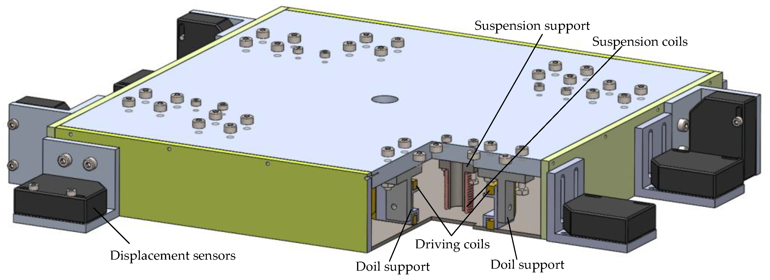
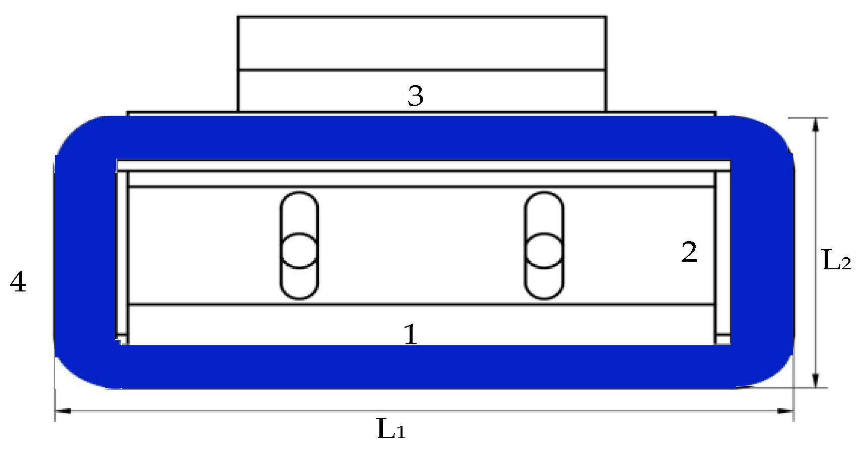
2. Structure and Working Principle

Figure 1 represents the structure of the novel six-degree-of-freedom magnetic suspension platform. The magnetic suspension platform in this paper is composed of the stator and the Lorentz force actuator. The stator includes the novel Halbach magnetic array, yoke, stator support frame, and signal reflector. The Lorentz force actuator includes four passive magnetic bearings, eight Lorentz-force-type magnetic bearings, four electromagnetic suspension bearings, and laser displacement sensors. Eight Lorentz-force-type magnetic bearings are installed under the moving platen for the x and y directions and horizontal rotation. Four electromagnetic suspension bearing are installed in the moving platen for moving in the z direction and z-axis rotation. Four passive magnetic bearings are used as a gravity compensator. The novel platform’s stator magnetic array consists of a permanent magnetic and magnetizer. The working principle of the novel platform is provided in Figure 2. The Lorentz-force-type magnetic bearings’ coils carrying a direct current are exposed to the magnetic field generated by the stator. Four electromagnetic suspension bearings’ coils carrying a direct current are also exposed to the magnetic field produced by the stator. The red arrow is the direction of the driving force that Lorentz-force-type magnetic bearings can provide, and the blue arrow is the direction of the driving force that the Lorentz-force-type magnetic bearings can provide. Therefore, the motion state of the platform is changed by changing the direction of the direct current in the coils.
The structure of the Lorentz force actuator is shown in Figure 3. The Lorentz-force-type magnetic bearings’ coils are fixed to the coil support frame, which is made of magnetic isolation material. The electromagnetic suspension bearings’ coil support frame is made of magnetizer, which can enhance the magnetic field generated by the current. The driving force and torque of the magnetic bearing are controlled by changing the direct current in the magnetic bearing windings. For instance, the driving force is outputted by Lorentz-force-type magnetic bearings 1 and 7 or the same bearing 4 and 11 together. The torque is outputted by Lorentz-force-type magnetic bearings 1 and 7 or the same bearing 4 and 11. The working principle along the Z-axis is performed by the electromagnetic suspension bearings. The mapping relationship between the platform motion and the magnetic bearings of the six-DOF platform is shown in Table 1.

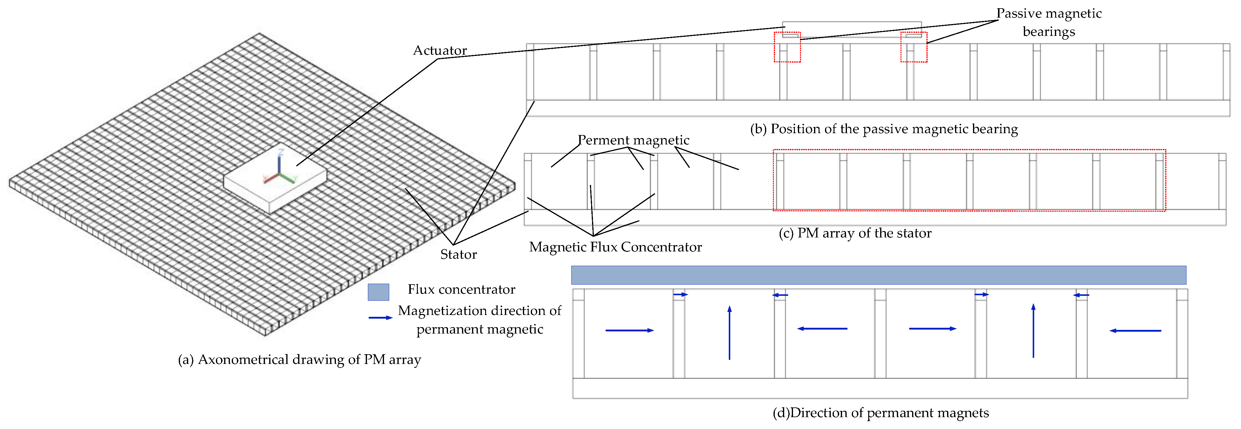
3. Improved Halbach Magnetic Array

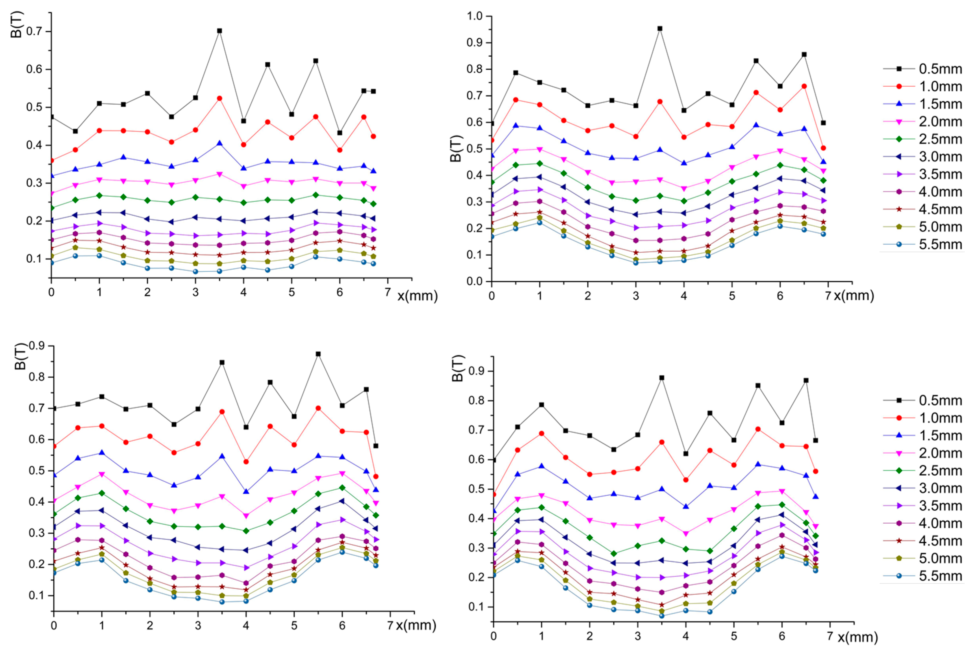
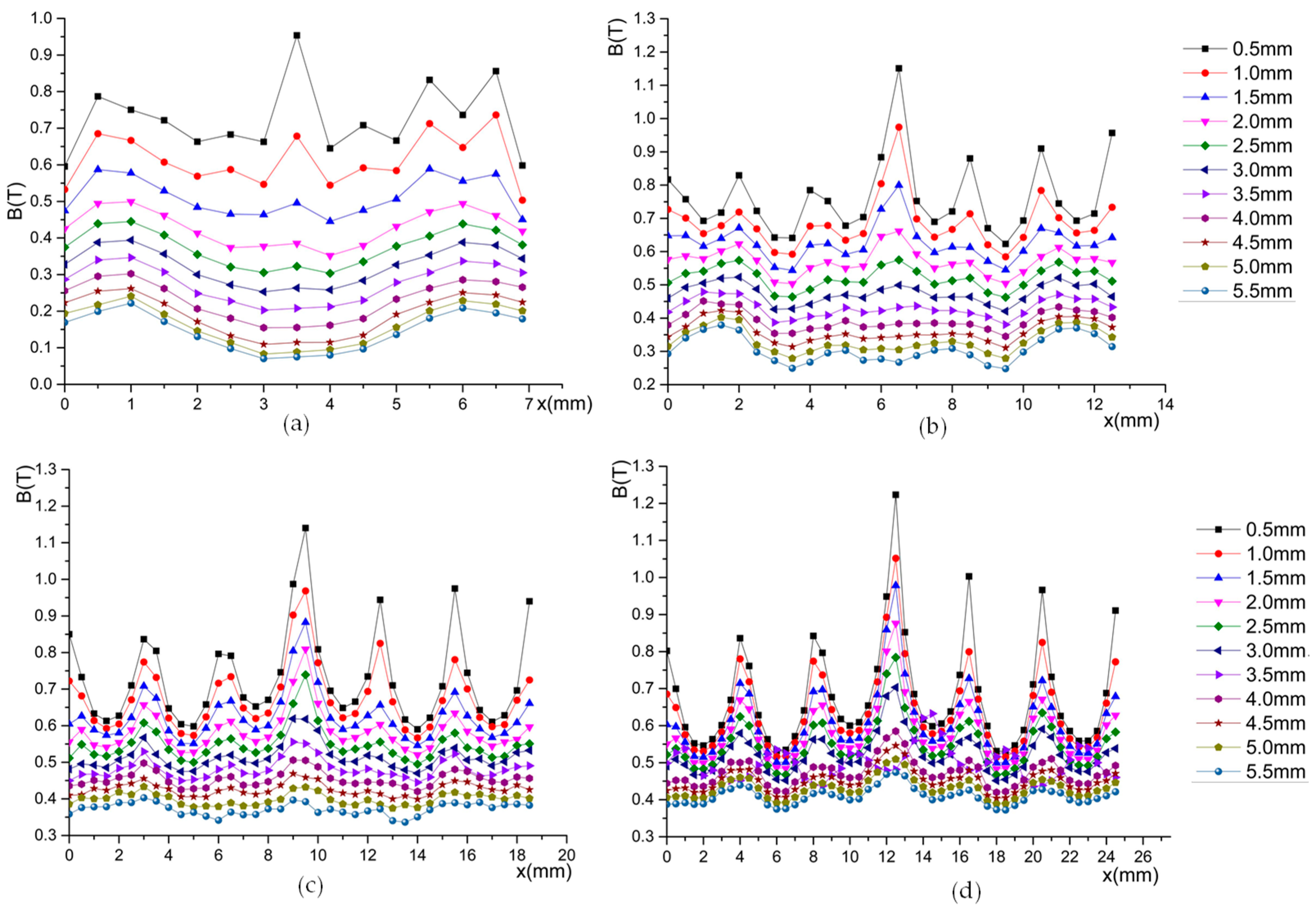
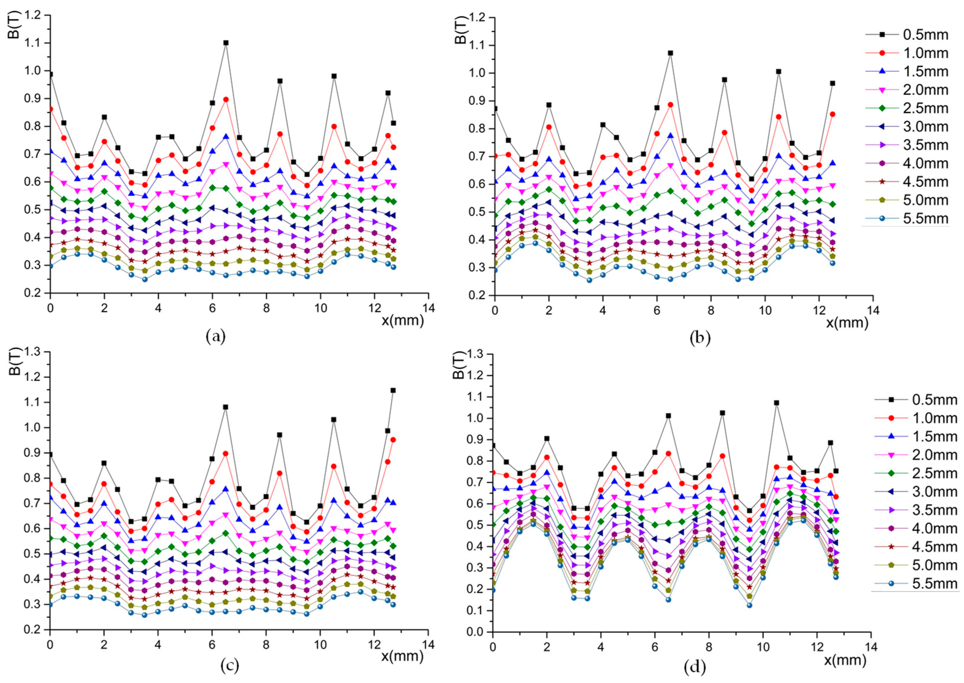
3.1. Model of the Magnetic Flux Density

To improve the start/stop acceleration, the magnetic flux density in the airgap needs to be increased using the Halbach magnetic array. As shown in Figure 4, a novel Halbach magnetic array is used. Two types of permanent magnets with the same magnetization direction and different volumes are used in the magnetic array. Large permanent magnets are linked to each other by magnetic conductors. The model of magnetic flux density in the airgap is established.
To solve the magnetic flux density in the airgap, the air gap is divided into many different areas. In one divided area, the relationship between the magnetomotive force F m and the magnetic flux ϕ is satisfied follows:
ϕ = B A m . F m = H l m
where Am is the magnetization direction’s area and lm is the length of the magnetization direction.
For the permanent magnetic, B and the H can be expressed as follows:
B = μ 0 H B = μ 0 μ r H + μ 0 M r
where μ r is the relative magnetic permeability, μ 0 is the vacuum magnetic permeability, and M r is the residual magnetization of the permanent magnet.
The magnetization direction of the permanent magnet is the X-axis or Y-axis. Then, M r can be expressed as follows:
M r = B r μ 0
For the improved Halbach magnetic array, M r in the cartesian coordinate system can be expressed as follows:
M r 1 = M x 1 + M y 1 M r 2 = M x 1 + M x 2 + M y 1 + M y 2
where M r 1 is the region 1 M r and M r 2 is the region 2 M r .
M x 1 , M y 1 , M x 2 , and M y 2 are described by the Fourier series.
{ M x 1 = a M 01 2 + n = 1 a M n 1 cos ( k ω x ) M y 1 = n = 1 b M n 1 sin ( k ω x )
{ M x 2 = a M 02 2 + n = 1 a M n 2 cos ( k ω x ) M y 2 = n = 1 b M n 2 sin ( k ω x )
where
a M 01 = 2 M r 1 ω 1 T , k 1 = n 1 π T . a M n 1 = 2 M r 1 n 1 π { sin [ k 1 ( 2 ω 1 + 3 ω 2 ) ] sin [ k 1 ( 2 ω 1 + ω 2 ) ] sin k 1 ω 2 } b M n 1 = 2 M r 1 n 1 π { cosk 1 l cos [ k 1 ( 2 ω 1 + 3 ω 2 ) ] cos [ k 1 ( 2 ω 1 + ω 2 ) ] + cos k 1 ω 2 } a M 02 = 2 M r 2 ω 2 T , k 2 = n 2 π T a M n 2 = 2 M r 2 n π { sin [ k 2 ( 2 ω 2 + 3 ω 1 ) ] sin [ k 2 ( 2 ω 2 + ω 1 ) ] sin k 2 ω 1 } b M n 2 = 2 M r 2 n 2 π { cosk 2 l cos [ k 2 ( 2 ω 2 + 3 ω 1 ) ] cos [ k 2 ( 2 ω 2 + ω 1 ) ] + cos k 2 ω 1 }
The magnetic vectors for region 1 and region 2 can be written as follows:
A 1 = n = 0 [ ( A n 1 e k y + B n 1 k y ) cos ( k 1 x ) + ( C n 1 e k y + D n 1 e k y ) sin ( k 1 x ) ] A 2 = n = 0 [ ( A n 2 e k y + B n 2 k y ) cos ( k 2 x ) + ( C n 2 e k y + D n 2 e k y ) sin ( k 2 x ) ]
As the magnetic flux density is continuous anywhere, we can obtain the following formula:
n × ( B 1 + B 2 ) = 0 n × ( H 1 + H 2 ) = J × S B = × A × H = J
With Formulas (1)–(8), the flux density in every region can be calculated. The finite element method is also used to prove the model of the magnetic flux density.

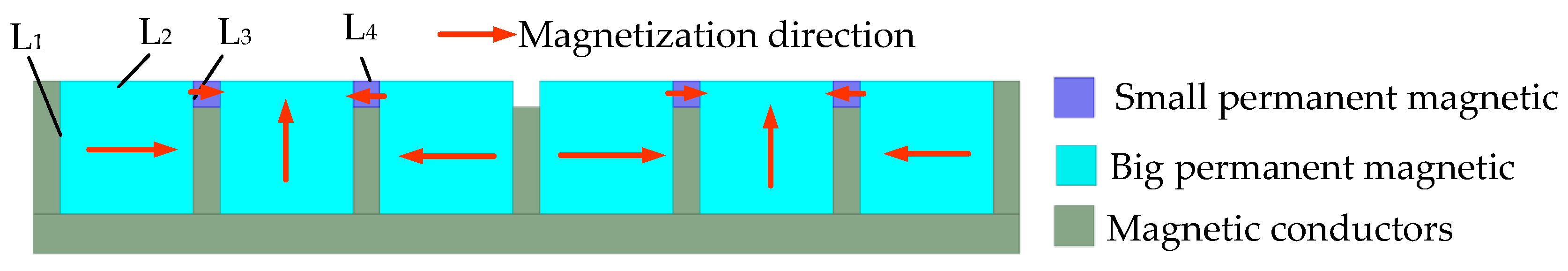
3.2. Size Optimization of the Permanent Magnet

To obtain the maximum magnetic flux density, it is necessary to optimize the size of the permanent magnetic of the two sides. As shown in Figure 5, four sizes (L1–L4) need to be optimized.
With the software Maxwell2021R1, the relation between magnetic flux density and the size of the permanent magnet was analyzed. First, L2–L4 are set as constants and the effect of L1 on the magnetic flux density in the air gap is analyzed. The 2D model is established in the Maxwell 2D design. Then, the variation law of the magnetic flux density in the air gap with L1 can be obtained. The variation law is shown as follows.
Figure 6 shows the variation law of magnetic flux density with L2. It can be seen from the figure that the magnetic flux density in the air gap will increase with the increase in L1. However, it will decrease as L1 increases when L1 increases to a certain extent. The magnetic density uniformity has the same variation pattern with the magnetic flux density. The optimal length of L1 is 8 mm, which is proved by the finite element method.
Figure 7 shows the variation law of magnetic flux density with L2. It can be seen from the figure that the maximum magnetic flux density in the air gap will not remain essentially constant with the L2 increasing. However, the magnetic density uniformity will decrease with the increase in L2. The optimal length of L2 is 4 mm, which is proved by the finite element method.
Figure 8 is the variation law of magnetic flux density with L3. It can be seen from the figure that the maximum magnetic flux density in the air gap will not remain essentially constant with the L3 increasing. However, when L3 is greater than 1/4 of L1, the magnetic density uniformity will be significantly reduced and does not meet the requirements of the platform with the magnetic density uniformity.
Figure 9 shows the variation law of magnetic flux density with L4. As shown in the figure, the maximum magnetic flux density in the air gap nearly remains same with the change in L4. However, the change in L4 has a large impact on the magnetic density uniformity. The magnetic density uniformity decreases significantly when L4 is larger than 1/4 of L2.
Table 2 shows the optimal magnet size for the novel Halbach magnetic array.

4. Stiffness of Magnetic Bearing

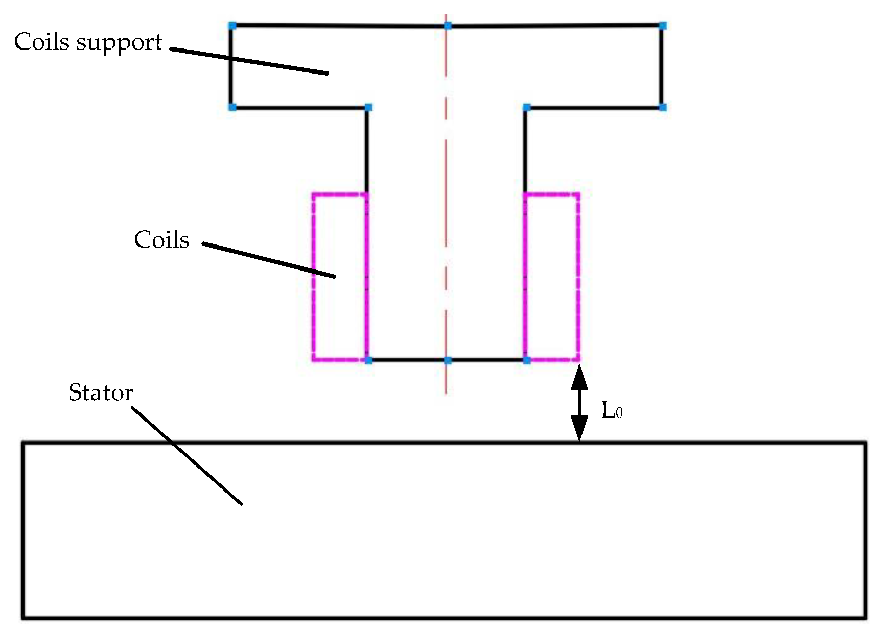
4.1. Stiffness of Lorentz-Force-Type Magnetic Bearings

A high stiffness is needed for the magnetic suspension platform to reduce the heat in the windings. Thus, it is necessary to analyze the stiffness of the magnetic bearings in the novel platform. The stiffness of the magnetic bearing is a function of the magnetic bearing. Then, the force needs to be solved first. The force of the Lorentz-force-type magnetic bearing is determined by the coils in it. Figure 10 shows the Lorentz force coil model.
As shown in Figure 10, L1 is the effective length of the coil that can provide the driving force and torque. L2 is the vertical length of the coil, which should be small, and can reduce the heat. The i-th Lorentz coil is analyzed. When the current is directed in a right-handed spiral with respect to the x-axis of the i-th coil, the driving force F i will be expressed as follows:
F i = n = 1 , 3 J n × B d V n + n = 2 , 4 J n × B d V n
where B is the magnetic flux density in the i-th Lorentz coil and J n is the volume current density of the i-th Lorentz coil of the I array of winding. As the coils are symmetrical about their central plane, Equation (9) will be expressed as follows:
F i = n = 1 , 3 J n × B d V n
The driving force of the Lorentz-force-type magnetic bearings can be expressed as follows:
F O i = p = 1 q m = 1 z n = 1 , 3 J n × B d V n i
where q is the number of energized coils and z is the number of coil turns.
The current stiffness of Lorentz-force-type magnetic bearings can be expressed as follows:
k c = ( p = 1 q m = 1 z n = 1 , 3 J n × B d V n ) i i
where i is the current in the coil of the Lorentz-force-type magnetic bearings.

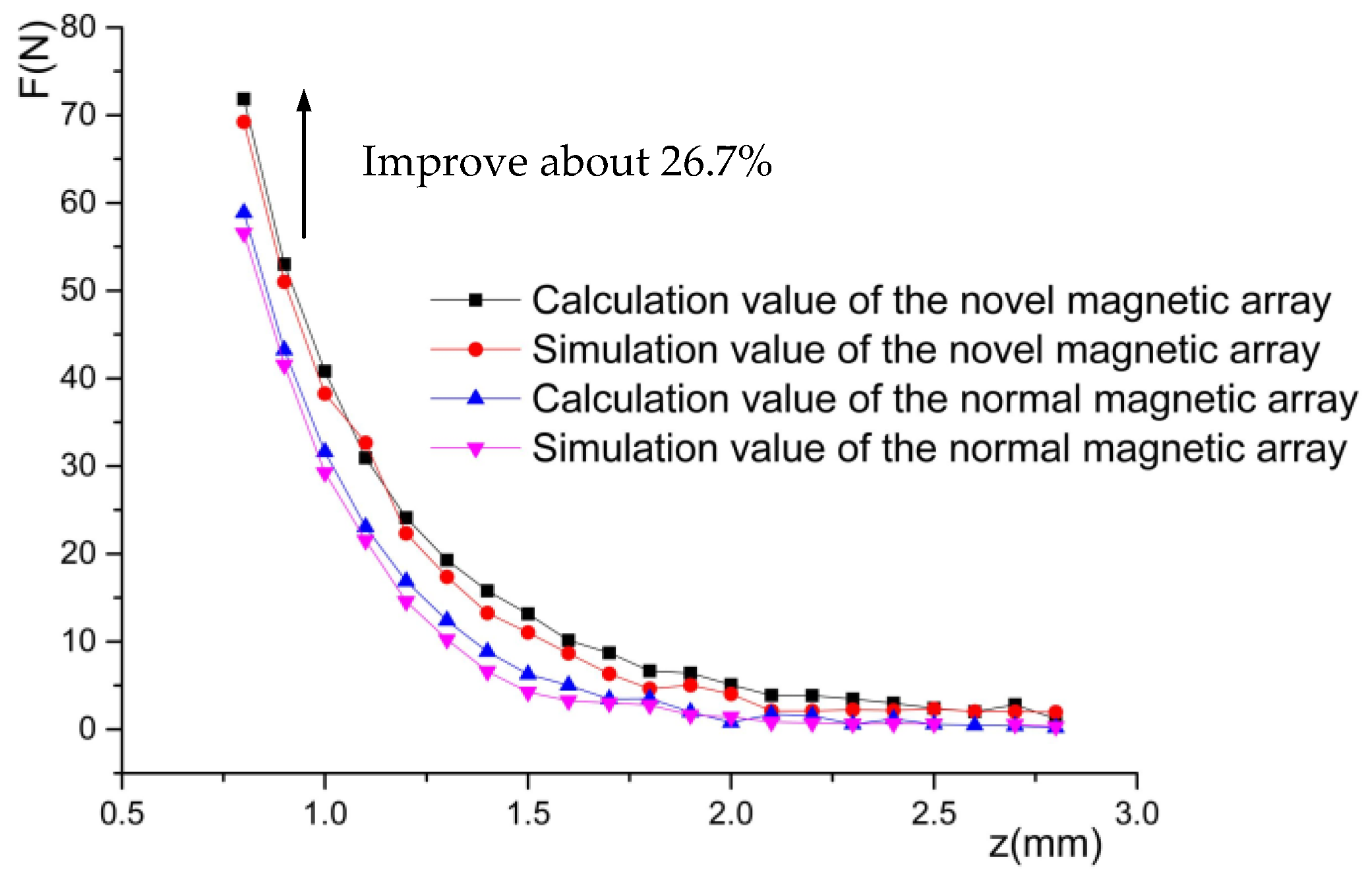
4.2. Stiffness of Passive Magnetic Bearing

The attractive or repulsive force of permanent magnets is employed in the passive magnetic bearing. The force can be express as follows:
F = J 1 J 2 4 π μ 0 i = 0 1 j = 0 1 k = 0 1 l = 0 1 p = 0 1 q = 0 1 ( 1 ) i + j + k + l + p + q φ ( u i j , v k l , w p q , r )
where J is the magnetizations and φ can be expressed as follows:
φ ( u , v , w , r ) = 1 2 u ( v 2 w 2 ) ln ( r u ) + 1 2 v ( u 2 w 2 ) ln ( r v ) + u v w tan 1 u v r w + r 6 ( u 2 + v 2 2 w 2 )
It is hard to use Equation (13) to solve the stiffness of the passive magnetic bearing. Another attractive or repulsive force of permanent magnets can be expressed as follows:
F = ± 1.5 1 + a L ( B 4865 ) 2 A p m
where Apm is the permanent magnetic area of the permanent magnet and L is the distance between the two permanent magnets.
The displacement stiffness of passive magnetic bearings can be expressed as follows:
k d = d F d L = d [ ± 1.5 1 + a L ( B 4865 ) 2 A p m ] d L

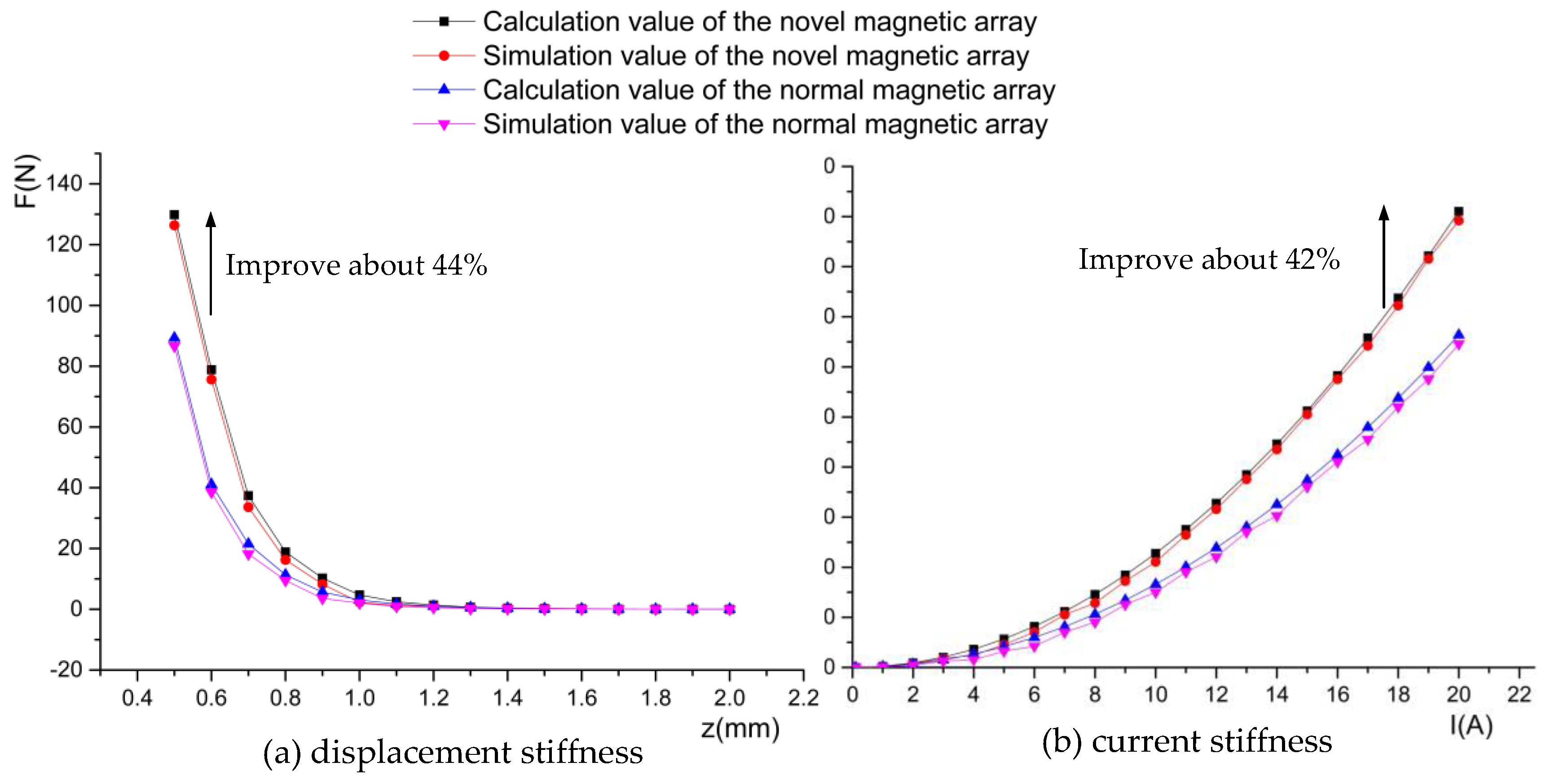
4.3. Stiffness of Electromagnetic Suspension Bearings

The model of the electromagnetic suspension bearing can be illustrated by Figure 11. The current in the coils can be employed to control the force of the vertical and the torque along the X-axis and Y-axis. It is necessary to establish its stiffness for controlling the position of the actuator.
When the actuator is in the equilibrium position, the current is zero. Thus, the force of the electromagnetic suspension bearings can be expressed as follows:
F = μ 0 S N 2 i 2 4 ( L L 0 ) 2
where μ 0 is the vacuum permeability, S is the cross-sectional area of the magnetic pole, N is the number of turns of the coil, i is the coil current, and L is the actuator travel distance.
The displacement stiffness of the electromagnetic suspension bearing can be obtained by deriving Equation (16) from L. The displacement stiffness can be expressed as follows:
k i = F L = μ 0 S N 2 i 2 4 ( L L 0 ) 3
The current stiffness of the electromagnetic suspension bearing can be obtained by deriving Equation (16) from i. The displacement stiffness can be expressed as follows:
k i = F i = μ 0 S N 2 i 8 ( L L 0 ) 2
Thus, the F can also be expressed as follows:
F = k i i + k l L

5. Analysis of the Stiffness

To verify the advantage of the improved Halbach magnetic array and the design of the platform’s controller, it is necessary to validate the stiffness models of the three magnetic bearings in this platform. The finite element method is used. The 3D model of the three types of magnetic bearing is established. With the software Maxwell, the stiffness of the three types magnetic bearing is compared. The passive magnetic bearing of the two schemes is shown in Figure 12.
It can be seen from Figure 12 that the stiffness of the passive magnetic bearing in the novel Halbach magnetic array is higher than its in normal Halbach magnetic array. The difference between the simulated and theoretical values is only 2.6%, which demonstrates the reliability of the finite element method. The maximum stiffness is about 79 N in the novel Halbach array, while it is only about 59 N in the normal array. The stiffness decays exponentially with the increase in displacement, which means the power consumption of the platform will quickly increase with the distance increasing in the Z-axis.
The displacement stiffness and current stiffness of the electromagnetic suspension bearings are illustrated by Figure 13. It can be seen from the figure that the stiffness of electromagnetic suspension bearings in the novel Halbach magnetic array is improved. The current stiffness is a curve, which is linear in Equation (18). It is because the magnetic field is enhanced as there is iron around the coil. The displacement stiffness is influenced by the distance along the Z-axis. So, the platform has a short stroke in the Z-axis.
Figure 13 represents the stiffness of the Lorentz-force-type magnetic bearings. It can be seen that the calculation values of the two schemes are a linear. This is because the magnetic flux density is considered to be a fixed value in the calculation. However, the magnetic flux density is not uniform. The actuator in different places along the Z-axis, and the magnetic flux density is not same. The small fluctuate exists in the same height along the Z-axis. As shown in Figure 14, the stiffness is changed. The stiffness of Lorentz-force-type magnetic bearings is about 1.8 N/A in the novel Halbach magnetic array, which is 1.2 N/A in the traditional Halbach magnetic array. The novel magnetic suspension platform has a low drive power consumption owing to the height current stiffness. The materials of the permanent magnetic in [33,34] are used in the novel Halbach magnetic array.

6. Conclusions

A novel magnetic suspension platform with three types magnetic bearings is proposed for mass transfer. The stroke of the platform is 300 mm × 300 mm × 5 mm. The overall dimension is 600 mm × 600 mm × 45 mm. The improved Halbach magnetic array is analyzed. The finite element method is used to optimize the size of the permanent magnets. The displacement stiffness and current stiffness model of the three magnetic bearings are established. The displacement stiffness and current stiffness value are compared. The result shows that the maximum stiffness of the passive magnet is 79 N in the novel Halbach magnetic array, and is only 59 N in the traditional array; the maximum stiffness of Lorentz-force-type magnetic bearings is 35.1 N in the novel Halbach magnetic array, and is 25.2 N in the traditional array; the displacement stiffness and current stiffness of electromagnetic suspension bearing are 129.8 N and 89.2 N, respectively, in the novel Halbach magnetic array, while they are 91.0 N and 66.3 N, respectively, in the traditional array. Compared with the traditional Halbach magnetic array, the novel platform in this paper has a big stroke and the structure is novel. Compared with the traditional suspension platform, the suspension power consumption of the novel platform is basically negligible owing to the use of the passive magnetic bearings.

Author Contributions

Conceptualization, S.C. and P.N.; methodology, S.C.; software, W.W.; validation, S.C., T.Z. and Q.L.; formal analysis, S.S.; investigation, S.S.; resources, P.N.; data curation, S.C.; writing—original draft preparation, S.C.; writing—review and editing, S.C.; visualization, J.B.; supervision, Q.L.; project administration, P.N.; funding acquisition, Q.L. All authors have read and agreed to the published version of the manuscript.

Funding

This research was funded by Beijing Natural Fund (grant nos. 3212004) and Award Cultivation Foundation from Beijing Institute of Petrochemical Technology (grant nos. BPTACF-0007). The paper was funded by the Joint Doctoral Program of Beijing Institute of Petrochemical Technology, Tianjin Municipal Education Commission Scientific Research Program Project (grant nos. 2019ZD08).

Institutional Review Board Statement

Not applicable.

Informed Consent Statement

Not applicable.

Data Availability Statement

Not applicable.

Conflicts of Interest

The authors declare no conflict of interest.

References

  1. Gao, W.; Dejima, S.; Yanai, H.; Katakura, K.; Kiyono, S.; Tomita, Y. A surface motor-driven planar motion stage integrated with an XYθZ surface encoder for precision positioning. Precis. Eng. 2004, 28, 329–337. [Google Scholar] [CrossRef]
  2. Kim, J.H. Robust Discrete-Time Variable Structure Control Method. Trans. Asme J. Dyn. Syst. Meas. Control 1992, 122, 766–775. [Google Scholar] [CrossRef]
  3. Kunioka, T.; Takeda, Y.; Matsuda, T.; Shimazu, N.; Nakayama, Y. XY stage driven by ultrasonic linear motors for the electron-beam x-ray mask writer EB-X3. J. Vac. Sci. Technol. B 1999, 17, 2917–2920. [Google Scholar] [CrossRef]
  4. Stevenson, J.; Jordan, J.R. Dynamic position measurement technique for flash-on-the-fly wafer exposure. Precis. Eng. 1989, 11, 127–133. [Google Scholar] [CrossRef]
  5. Kim, W.J.; Trumper, D.L. High-precision magnetic levitation stage for photolithography. Precis. Eng. 1998, 22, 66–77. [Google Scholar] [CrossRef]
  6. Whorton, M. g-LIMIT-A Vibration Isolation System for the Microgravity Science Glovebox. In Proceedings of the 37th Aerospace Sciences Meeting and Exhibit, Reno, NV, USA, 11–14 January 1999. [Google Scholar]
  7. Kim, W.J.; Maheshwari, H. In High-precision control of a maglev linear actuator with nanopositioning capability. In Proceedings of the American Control Conference, Anchorage, AK, USA, 8–10 May 2002. [Google Scholar]
  8. Sang, H.L.; Baek, Y.S. Magnetically Suspended Contact-Free Linear Actuator for Precision Stage. Ksme Int. J. 2003, 17, 708–717. [Google Scholar]
  9. Kim, W.J.; Bhat, N.; Hu, T. Integrated multidimensional positioner for precision manufacturing. Proc. Inst. Mech. Eng. Part B J. Eng. Manuf. 2008, 431–442. [Google Scholar] [CrossRef] [Green Version]
  10. Verma, S.; Shakir, H.; Kim, W.J. Novel Electromagnetic Actuation Scheme for Multiaxis Nanopositioning. IEEE Trans. Magn. 2006, 42, 2052–2062. [Google Scholar] [CrossRef] [Green Version]
  11. Estevez, P.; Mulder, A.; Schmidt, R. 6-DoF miniature maglev positioning stage for application in haptic micro-manipulation. Mechatronics 2012, 22, 1015–1022. [Google Scholar] [CrossRef]
  12. Zhang, Z.; Menq, C.H. Six-axis magnetic levitation and motion control. IEEE Trans. Robot. 2007, 23, 196–205. [Google Scholar] [CrossRef]
  13. Dejima, S.; Gao, W.; Shimizu, H.; Kiyono, S.; Tomita, Y. Precision positioning of a five degree-of-freedom planar motion stage. Mechatronics 2005, 15, 969–987. [Google Scholar] [CrossRef]
  14. Chen, M.Y. Design and Experiment of a Macro–Micro Planar Maglev Positioning System. IEEE Trans. Ind. Electron. 2012, 59, 4128–4139. [Google Scholar] [CrossRef]
  15. Xu, F.; Xu, X.; Chen, M. Prototype of 6-DOF Magnetically Levitated Stage Based on Single Axis Lorentz force Actuator. J. Electr. Eng. Technol. 2016, 11, 1216–1228. [Google Scholar] [CrossRef] [Green Version]
  16. Yang, F.; Zhao, Y.; Li, H.; Mu, X.; Zhang, W.; Yue, H.; Liu, R. Design and Analysis of a 2-DOF Electromagnetic Actuator with an Improved Halbach Array for the Magnetic Suspension Platform. Sensors 2022, 22, 790. [Google Scholar] [CrossRef] [PubMed]
  17. Lee, D.J.; Lee, K.N.; Park, N.C.; Park, Y.P.; Lee, D.J. Development of 3-axis nano stage for precision positioning in lithography system. In Proceedings of the Mechatronics & Automation, IEEE International Conference, Niagara Falls, ON, Canada, 29 July–1 August 2005. [Google Scholar]
  18. Zhang, H.; Kou, B.; Zhou, Y. Analysis and design of a novel magnetic levitation gravity compensator with low passive force variation in a large vertical displacement. IEEE Trans. Ind. Electron. 2019, 67, 4797–4805. [Google Scholar] [CrossRef]
  19. Takahashi, M.; Ogawa, H.; Kato, T. Compact maglev stage system for nanometer-scale positioning. Precis. Eng. 2020, 66, 519–530. [Google Scholar] [CrossRef]
  20. Prosen, N.; Milanovič, M.; Domajnko, J. Magnetic Flux Density Measurement Platform for an Inductive Wireless Power Transmitter Coil Design. Sensors 2022, 22, 479. [Google Scholar] [CrossRef] [PubMed]
  21. Li, B.; Liu, Z.; Wang, L.; Li, Y. Design of Hybrid Magnetic Stage for a Magnetic–Pneumatic Levitation System. IEEE Trans. Magn. 2022, 58, 8001108. [Google Scholar] [CrossRef]
  22. Li, Z.; Wu, Q.; Liu, B.; Gong, Z. Optimal Design of Magneto-Force-Thermal Parameters for Electromagnetic Actuators with Halbach Array. Actuators 2021, 10, 231. [Google Scholar] [CrossRef]
  23. Choi, Y.; Gweon, D. A High-Precision Dual-Servo Stage Using Halbach Linear Active Magnetic Bearings. IEEE/ASME Trans. Mechatron. 2011, 16, 925–931. [Google Scholar] [CrossRef]
  24. Britcher, C.P.; Ghofrani, M. A magnetic suspension system with a large angular range. Rev. Sci. Instrum. 1993, 64, 1910–1917. [Google Scholar] [CrossRef] [Green Version]
  25. Molenaar, L.; Zaaijer, E. A Novel Long Stroke Planar Magnetic Bearingactuator. In Proceedings of the 4th International Conference on Motion and Vibration Control, Zurich, Switzerland, 25–28 August 1998; pp. 1071–1076. [Google Scholar]
  26. Jabben, L.; Overschie, P.M.; Molenaar, A. Lorentz Motor with Stationary Magnets and Coils Applied in a 6DOF Contactless Motion Stage. In Proceedings of the ASPE Spring Topical Meeting on Control of Precision Systems, Philadelphia, PA, USA, 18–20 April 2014. [Google Scholar]
  27. Rovers, J.; Jansen, J.W.; Compter, J.C.; Lomonova, E.A. Analysis Method of the Dynamic Force and Torque Distribution in the Magnet Array of a Commutated Magnetically Levitated Planar Actuator. IEEE Trans. Ind. Electron. 2012, 59, 2157–2166. [Google Scholar] [CrossRef]
  28. Cao, S.; Niu, P.; Liu, Q.; Li, J.; Gao, Q.; Peng, C. In Design and Analysis of the Magnetic Circuit and Vibration of LMLP for Mass Transfer. In Proceedings of the 2021 IEEE 15th International Conference on Electronic Measurement & Instruments (ICEMI), Nanjing, China, 2–4 November 2021; pp. 104–108. [Google Scholar]
  29. Schaeffel, C.; Katzschmann, M.; Mohr, H.U.; Gloess, R.; Walenda, C. 6D planar magnetic levitation system-PIMag 6D. Mech. Eng. J. 2015, 3, 15-00111. [Google Scholar] [CrossRef] [Green Version]
  30. Takahashi, M. Design Concept and Structural Configuration of Magnetic Levitation Stage with Z-Assist System. Int. J. Autom. Technol. 2021, 15, 706–714. [Google Scholar] [CrossRef]
  31. Berkelman, P.; Lu, Y.-S. Long range six degree-of-freedom magnetic levitation using low cost sensing and control. J. Robot. Mechatron. 2020, 32, 683–691. [Google Scholar] [CrossRef]
  32. Zhang, X.; Trakarnchaiyo, C.; Zhang, H.; Khamesee, M.B. MagTable: A tabletop system for 6-DOF large range and completely contactless operation using magnetic levitation. Mechatronics 2021, 77, 102600. [Google Scholar] [CrossRef]
  33. Arief, I.; Mukhopadhyay, P. Magnetorheology in CoNi nanoplatelet-based MRFs: Effect of platelet orientation and oscillatory shear. J. Magn. Magn. Mater. 2019, 479, 326–331. [Google Scholar] [CrossRef]
  34. Arief, I.; Mukhopadhyay, P. Two-step yielding in novel CoNi nanoplatelet-based magnetic fluids under oscillatory rheology. Mater. Lett. 2016, 167, 192–196. [Google Scholar] [CrossRef]
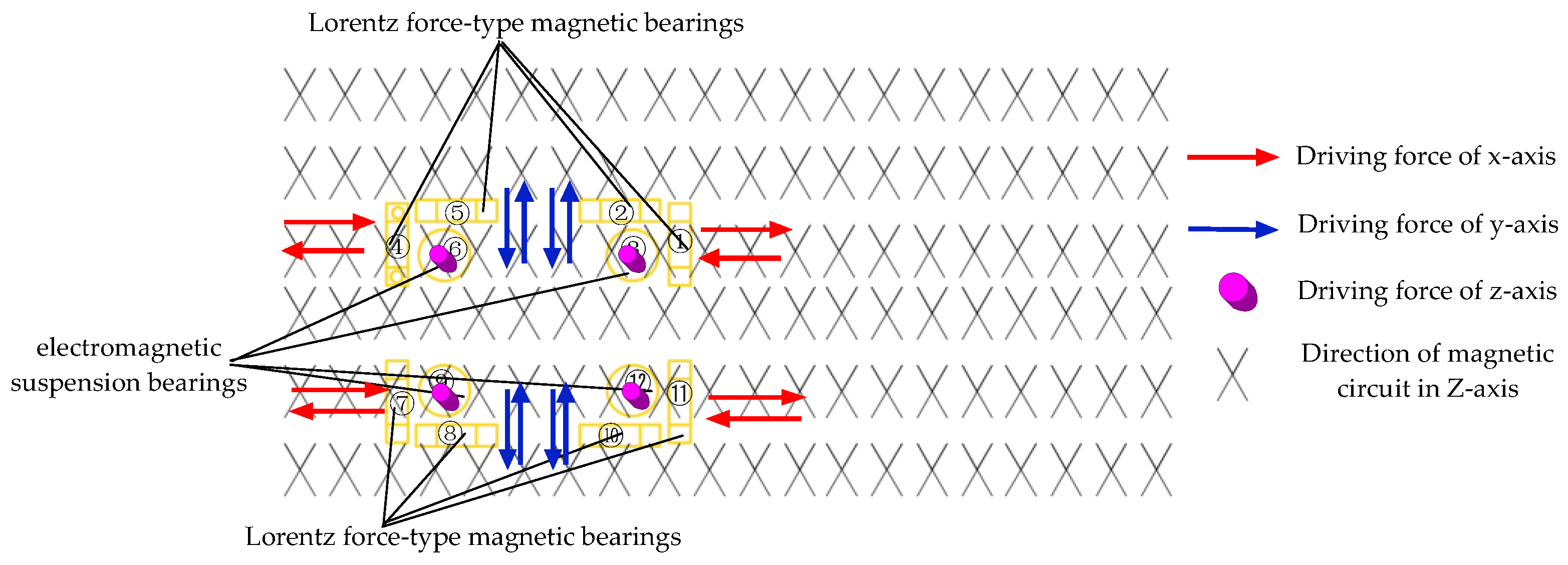
Figure 1. The structure of the six-DOF magnetic suspension platform.
Energies 15 05691 g001
Figure 2. Working principle of the six-DOF magnetic suspension platform.
Energies 15 05691 g002
Figure 3. Actuator of the six-DOF magnetic suspension platforms.
Energies 15 05691 g003
Figure 4. Improved Halbach magnetic array.
Energies 15 05691 g004
Figure 5. Size of the two permanent magnets.
Energies 15 05691 g005
Figure 6. Variation law of magnetic flux density with L1.
Energies 15 05691 g006
Figure 7. (ad) Variation law of magnetic flux density with L2.
Energies 15 05691 g007
Figure 8. (ad) Variation law of magnetic flux density with L3.
Energies 15 05691 g008
Figure 9. (ad) Variation law of magnetic flux density with L4.
Energies 15 05691 g009
Figure 10. Model of the Lorentz coils.
Energies 15 05691 g010
Figure 11. Model of electromagnetic suspension bearings.
Energies 15 05691 g011
Figure 12. Stiffness of the two schemes passive magnetic bearings.
Energies 15 05691 g012
Figure 13. Stiffness of the electromagnetic suspension bearings.
Energies 15 05691 g013
Figure 14. Stiffness of the Lorentz-force-type magnetic bearings.
Energies 15 05691 g014
Table 1. The relationship between the motion of the platform and magnetic bearing.
Movement of the PlatformDriving Force/Torque
Translation in X-axis direction of O-XYZLorentz-force-type magnetic bearings 1 and 7 or 4 and 11
Translation in Y-axis direction of O-XYZLorentz-force-type magnetic bearings 5 and 10 or 2 and 8
Translation in Z-axis direction of O-XYZelectromagnetic suspension bearings 3, 6, 9, 12
Rotate around X-axis of O-XYZelectromagnetic suspension bearings 3, 6 and 9, 12
Rotate around Y-axis of O-XYZelectromagnetic suspension bearings 3, 12 and 6, 9
Rotate around Z-axis of O-XYZLorentz force-type magnetic bearings 1 and 7 or 4 and 11 or 5 and 10 or 2 and 8
Table 2. Optimal size of permanent magnets.
SizeValue (Unite: mm)
L18
L24
L3L1/4
L4L2/4
Publisher’s Note: MDPI stays neutral with regard to jurisdictional claims in published maps and institutional affiliations.

