Next Article in Journal
Air-Type Vacuum-Tube Solar Collector Design and Heat Collection Performance Test
Previous Article in Journal
On the Organisation of Translation—An Inter- and Transdisciplinary Approach to Developing Design Options for CO2 Storage Monitoring Systems
 
 
Order Article Reprints
Article

UAV Support for Mission Critical Services

1
Institute of Telecommunications, Faculty of Electronics and Information Technology, Warsaw University of Technology, 00-665 Warsaw, Poland
2
Orange Polska, 02-691 Warsaw, Poland
3
Cedric Laboratory, Networks and IoT Systems Group, Conservatoire National des Arts et Metiers, 75003 Paris, France
*
Author to whom correspondence should be addressed.
Energies 2022, 15(15), 5681; https://doi.org/10.3390/en15155681
Received: 3 June 2022 / Revised: 27 July 2022 / Accepted: 29 July 2022 / Published: 5 August 2022
(This article belongs to the Section F3: Power Electronics)

Abstract

:
Mission critical solutions are essential for providing communications and services in the case of the troubles with connectivity that are often found in infrastructure-based solutions. Such solutions are typically used in the case of disasters, lack of energy, etc. There exist several narrowband solutions that provide countrywide coverage in certain countries. In recent years, the activities related to creating mission-critical broadband solutions based on Long Term Evolution (LTE) have led to the definition of LTE Mission Critical (LTE-MC). Both solutions ignore virtualization and require dedicated mobile terminals as a part of the mission-critical communication solution. This paper describes the opportunities, open issues and a proposal of a solution that exploits Unmanned Aerial Vehicles (UAVs) and network virtualization for mission-critical services. The presented approach combines Cloud/Edge and Fog orchestration to efficiently use all the available resources, including virtualized resources of the end-user devices.

1. Introduction

A Mission-Critical System (MCS) provides communication in an area where the classical, infrastructure-based solutions do not provide connectivity due to a lack of coverage (forests or jungles), power grid failure and as a result of disasters (earthquakes, floods and fires), etc. The most popular at present MCSs were developed nearly 30 years ago, mostly to handle voice services. These solutions include Terrestrial Trunked Radio (TETRA) [1], Terrestrial Trunked Radio Police (TETRAPOL) [2] and Project 25 (P25) [3].
These systems are deployed in several countries on a country-wide level, regional level or locally (airports, etc.). Their key features are the capability to work without infrastructure support, direct communications between terminals and so-called “Push-to-Talk” functionality. Such systems can be installed on demand or as permanent, private networks. A problem with the mentioned solutions is a limited set of narrowband services and a lack of data transmission capability. Moreover, these solutions use outdated, inflexible and ineffective technological solutions.
It is surprising, but almost two decades after the development of the solutions mentioned above, there has been no research or standardization activity related to the development of new, more functionally rich MCS. Recently, as a result of technological progress, widespread deployment of broadband telecommunications, including the global deployment of LTEs [4], interest in the deployment of broadband MCSs has grown. The main driver is the limited data transmission capability of narrowband MCS. As developing a completely new solution is costly, some research groups have looked into adapting existing solutions for broadband MCS. The selected solution is LTE-MC [5], a modification of LTE that is standardized by 3GPP. LTE has an efficient radio interface, relatively simple core network and the capability to deploy services in the “over IP” mode.
However, some modifications are needed to support direct communication between User Equipments (UEs) and services in a “Push-to-X” style. The concept at the time of writing the paper has not been deployed yet. LTE-MC is a broadband solution designed to provide several services only. However, the modern Information and Communications Technology (ICT) solutions require more support. In that context, IoT solutions (including the Smart City concept), Vehicle to Everything (V2X) services, e-Health, Industry 4.0 and IP-based client-server applications are worth mentioning. The solutions mentioned above require reliable communication and a reliable service platform. Unfortunately, most commercial service platforms, including clouds, are prone to disasters, terrorist attacks or power grid failure. The battery-powered backup power supplies can handle only a temporary lack of power (typically a few hours).
The network virtualization and UAV systems can be seen as technological enablers for a new generation of MCS. This paper presents a concept called Virtualized Mission Critical System (VMCS) that combines both technologies. It has the following key features:
  • Exploits UAV mobility for on-demand deployments of MCS. This covers both the delivery capability of UAVs and using UAVs as a mobile communications node.
  • Exploits the virtualization of commercial mobile network terminals to use them for MCS communications and ad hoc implementation of service platforms. These service platforms can replace platforms that stopped functioning due to disaster or power grid failure but also platforms that are dedicated solely to MCS services.
The VMCS concept goal is to exploit all the existing resources efficiently and, by using the resources virtualization technology, also flexibly implement services. This goes far beyond LTE-MC capabilities; however, it comes with the price of complexity and many new research challenges. The paper’s primary goal is to describe the overall concept and indicate solutions to some VMCS-related problems. According to our knowledge, this is the first approach attempting to use virtualization combined with UAVs in applications for MCS. The UAVs are already used in rescue actions; however, there is no uniform framework for their usage for such applications, which raises many operational problems. As the proposed solution is complex, the paper can be seen as paving the road in showing possibilities and challenges but not as a complete solution.
The structure of the paper is following. To better understand the value of the proposed concept, in Section 2 of the paper, we describe the features of the existing MCS solutions, both narrowband and broadband. Section 3 provides an overview of the UAV characteristics, classification and approaches to using UAVs for enhancing communication and service platforms. Section 4 describes different scenarios of the usage of UAVs in MCS. Section 5 describes the VMC concept, developed by the paper’s authors, using virtualization technologies up to the end-user terminals to provide MCS functionalities. The role of UAVs in this solution is also described. Finally, Section 6 concludes the paper by proposing future research directions.

2. Status of Mission-Critical Solutions

TETRA [1], TETRAPOL [2] and Project 25 (P25 or APCO-25) [3] are the narrowband networking solutions that belong to the MCS category. The most popular out of the three is TETRA, which is a standard for digital radio-telephony dispatcher (trunked) communication developed by European Telecommunications Standards Institute (ETSI) in 1995 and designed particularly for public safety and rescue services. TETRA uses Time-Division Multiple Access (TDMA) for the simultaneous handling of four separate conversations or data transmission sessions on a single 25 kHz radio channel.
The system can operate in several radio bands, including 380/410/450/870 MHz. TETRA is mainly used for voice communication (including group and peer-to-peer communication). The voice channel has a bitrate of 7.2 kbps, and data transmission (depending on the signal level, i.e., the distance from the antenna) ranges from 2.8 to 28 kbps in the 25 kHz channel and 80–157 kbps in the latest versions of the standard named TETRA Enhanced Data Service (TEDS). All calls are half-duplex, and only up to two calls per frequency carrier are allowed, which impacts the system capacity. Figure 1 [6] shows a simplified TETRA architecture.
TETRA works in two modes:
  • Trunked Mode Operation (TMO). In this mode, a fixed private TETRA infrastructure with TETRA base stations is used. This mode, in general, cannot be used in disasters.
  • Direct Mode Operation (DMO). This mode allows direct communication between the TETRA mobile nodes (TMNs) without support from the TETRA infrastructure.
The main advantages of the TETRA are the direct communication between terminals, group communication, the ability to operate the terminal as a connection relay to an infrastructure network and Push-to-Talk calls. TETRA also allows the exchange of short messages (SDS) that can be seen as the TETRA version of Short Message Service (SMS). The system provides authentication of connections and a high level of security.
TETRA is undoubtedly successful—it has been installed on the island basis in 114 countries and is used by the police, emergency services, airports, railways, etc. It covers the entire territory of Malaysia, Sudan, Egypt, Namibia, Belgium, the Netherlands, Croatia, Serbia, Denmark, Germany, Greece, Finland, Sweden, Ireland, Romania, Great Britain, Israel and Brazil.
The narrowband MCS solutions were designed long ago, mostly for classical Plain Old Telephone Service (POTS) services, and the progress of communication technologies has made them outdated. The deployment of broadband access (wired and mobile network-based), Internet of Things (IoT) systems, Smart City and Industry 4.0 concepts, and the automation of power grid and gas systems have created new MCS requirements that narrowband MCS solutions cannot meet. The most important feature, apart from voice and video services, has become data transmission, which is the Achilles’ heel of narrowband MCS.
To solve the lack of a broadband MCS, the EU has started projects on broadband Public Protection & Disaster Relief (PPDR). In February 2019, as part of the BroadWay project, a call for tenders was published to find solutions for introducing a pan-European mobile broadband public safety system. A natural candidate for such a network is LTE, a relatively simple and efficient wireless network. LTE, however, requires modifications to cope with MCS requirements. Such changes should enable the proper working of the new solution even if part of the network will fail and should support push-to-talk and other services that TETRA already supports.
In such applications, the advantages of LTE include video communication, low-latency IoT traffic handling and broadband data transmission. The standardization of the new mission-critical communication solution, called LTE-MC, is performed using 3GPP and is still in progress [5]; however, LTE-MC is the only broadband MCS with significant international and standardization support. Its data transmission capacity is at least two orders of magnitude greater, and its functionality is much richer than TETRA.
The LTE-MC architecture is similar to LTE (see Figure 2). It should be noted; however, that LTE to LTE-MC adaptation requires a significant effort—several new 3GPP specifications have been already published, and at least several dozens have been updated. Before the Rel 13 version (2016), the 3rd Generation Partnership Project (3GPP) started working on mechanisms useful for implementing LTE-MC services. In particular, LTE-MC uses multicast/broadcast eMBMS (Enhanced Multimedia Broadcast and Multicast Service) communication [7], group connections (GCSE) [8], extensions to the IMS platform [9] and device-to-device communication services, Proximity-based Services (ProSe) [10].
Thus far, the ProSe services are used for car-to-car communication V2X and are expected to be used for UAV-to-UAV communication, particularly in the context of a swarm. These services enable the terminal to be used for direct device-to-device (D2D) communications or a relay in such communications. Some enhancements, however, are needed regarding the use of ProSe services for MCS. The mission-critical service requirements for mission-critical communication described in [11,12,13,14] (Rel 13 and 14) were largely met by the LTE architecture and protocol specifications of Rel 13, 14 and 15.
3GPP standards provide the possibility of using LTE for advanced dispatch communication, including Push-to-Talk, Push-to-Video, location of users/devices, the possibility of integration with biometric or chemical sensors, the determination of brigades’ position in the field and prioritization of resource allocation and user connections in networks based on commercial infrastructure. 3GPP Rel 14 introduces extensions to Mission-Critical Push-to-Talk (MCPTT) [11], Mission-Critical Data (MCData) [14] and Mission-Critical Video (MCVideo) [13] services. The combined LTE-MC and IMS platform fully emulates TETRA network voice services (group communication, Push-to-Talk). In [15], an overview of 4G mechanisms used for public safety is presented. The 3GPP is still working on:
  • the operating mode of the base station without connection to the network (MCS support in the Isolated Operation for Public Safety mode of operation, [16]) and
  • extensions to existing standards regarding location functions [17].
An issue with the LTE-MC is the lack of available terminals supporting the ProSe services and their limited—by the current specifications—power, which provides a range of 1 km only for the 700 MHz band. A complete LTE network in the form of a knapsack was developed to ensure coverage in areas with no power supply. Such solutions only require a connection to the IP network for commissioning. They can be put into operation in several minutes, provide a range of several kilometres and have relatively low power consumption.
Using such solutions significantly impacts the deployment strategies of MCS solutions. This means that, instead of building infrastructure across the country that can operate for a relatively long time in the absence of power (the TETRA case), a system of mobile LTE stations can be created within a few hours (i.e., the time when batteries power the normal infrastructure) can provide coverage for a selected area.
By definition, it is not the area of the entire country or province. However, such a solution, which can be called LTE-MC On-Demand, should be standardized by 3GPP, which will significantly popularize its implementation. The basis of the work may be the recommendation for the operation of the LTE-MC base station in the absence of a backhaul to the Evolved Packet Core (EPC) network [16]. In many countries, where narrowband critical communication networks (TETRAPOL and TETRA) have been installed, the migration to broadband solutions is now ongoing. A concise comparison of TETRA and LTE-MC is provided in Table 1.
The 5th Generation (5G) network is an evolution of LTE. The first complete 3GPP standards describing the 5G network appeared in December 2018 [18], and the first implementation was in April 2019. At present, 5G networks are being deployed all over the world. The New Radio (NR) (5G RAN), uses new frequency bands, including 3.5–3.7, 12 and 28 GHz. The use of high bands enables the creation of much wider channels than LTE and provides an increased capacity of the base station in relation to the LTE network. Additional techniques, such as dynamic beam shaping and massive Multiple Input Multiple Output (MIMO) multi-antenna systems, improve the system’s capacity.
A 5G network can handle many virtualized mobile communication networks using a technique called Network Slicing (NS) [19]. The 5G backbone network, called 5G Core (5GC), supports NS, system virtualization using the Network Function Virtualisation (NFV) paradigm and the creation of control plane applications using the publish-subscribe Service-Based Architecture (SBA) [18].
The system offers a programming interface for developers of service applications. The works on the usage of 5G for MCS have started; however, they are still at the preliminary phase [20]. The NS technology can be nicely used for the low-cost creation of permanent MCS that, despite sharing of common, commercial infrastructure is isolated. Such a solution can be used by police, etc. Unfortunately, the existing 3GPP to NS approach gives no mechanisms to make reliable and disaster-prone NS. This makes it impossible to use 5G for disaster handling.
Despite 5G SBA and NS making the solution a good candidate for MCS, some other 5G features, such as the use of high-frequency bands (which implies a small serving area of 5G cells) and higher complexity (which implies high energy consumption) makes LTE the solution of choice for broadband MCS, particularly for on-demand applications. The main advantages of 5G, which are high-capacity and high-throughput, have limited value for MCS.
However, integration of 5G with Non-Terrestrial Network (NTN)—a topic that is actually under standardization by 3GPP [21]—can be fully exploited for disaster handling by 5G. NTN can support terrestrial networks in areas where there is no terrestrial connectivity or such connectivity has been disturbed. NTN can Low Earth Orbit (LEO) satellite networks (500–2500 km and 4 ms propagation time), Medium Earth Orbit (MEO) satellite networks, High Altitude Platform System (HAPS). Issues with this approach are the lack of maturity of the solution and the lack of appropriate terminals for direct NTN communication.

3. UAV Characteristics, Classifications and Commercial Deployments Status

UAVs were developed almost 50 years ago for military services. They recently expanded to non-military applications, including forestry, aerial photography, real-time video transmission, product deliveries, agriculture, surveillance and infrastructure inspections, including power grid or road traffic monitoring [22]. The UAV market has exploded in the last few years due to the large-scale production of small, quadcopter type UAVs with efficient batteries and electrical engines. Along with the amateur usage, there is also interest in the large-scale commercial use of this technology.

3.1. Classification of UAVs

The UAVs have been divided into several categories depending on their construction type, size, speed, altitude, range, flight autonomy level and load-carrying capabilities. An extensive overview of different UAV classification approaches is presented in [23,24]; however, there is no single international classification of UAVs. A classification in terms of size, altitude, range and endurance proposed by the US Department of Defense [25] presented in Table 2) is widely used.
The most popular are multi-rotor UAVs (quadcopters, hexacopters or multicopters in general) due to their small size, low price, low inertia and easiness of control. They belong to the Vertical Take-Off and Landing (VTOL) category. Fixed-Wing UAVs are primarily used for transportation and surveillance on longer distances (>10 km). Such drones have weaker manoeuvrability than multi-rotor UAVs; however, they are more energy efficient due to the gliding capability and the use of combustion or jet engines. The differences between the two categories are shown in Table 3.
The UAVs can typically fly with a speed of 60 km/h. The 3GPP specifications assume communication support for UAVs that can fly at a speed up to 120 km/h at a height in the range of 300 m above the ground level [27].

3.2. UAVs as Transportation Means

The transportation capabilities of so-called “delivery UAVs” are dependent on their size and construction. Multi-rotor delivery UAV speed is typically limited to 60 km/h, and they can typically carry a payload of approximately 1.5 kg for 30 to 60 min of flight time [28]. In Table 4 [22], the characteristic transportation capabilities of UAVs are provided.
Postal companies have already used such drones, and they were used to transport medicinal products (blood products, vaccines and pharmaceuticals) in areas where the road infrastructure is not well-developed. In that context, it is worth mentioning the Zipline company, which, by October 2020, had made over 70 thousand medical deliveries by UAVs using fixed-wing electric UAVs [29]. There have also been attempts to use UAVs for food delivery. Wing [30] can carry parcels up to 1.5 kg and fly beyond the light of sight.
Wing UAVs operates in some areas of several countries, including the USA, Australia and Finland, and by August 2021, they had delivered over 100 thousand parcels. An example of a powerful delivery UAV is the FB3 Heavy-Payload Cargo Drone [31] that is a multi-copter with eight rotors powered by rechargeable batteries. The UAV can carry up to 100 kg of a payload. Its empty weight is 70 kg, and it can fly from 10 to 40 min.
An important problem concerning delivery UAVs is the lack of standardized hook mechanisms for transportation of parcels UAVs. Such a hook is needed for automated pickup and delivery of parcels. The delivery UAVs may play a significant role in MCS solutions; however, in some cases, it may be necessary to realize several UAV missions to deliver a solution composed of several components that have to be assembled at the destination. It concerns, for example, a portable base station composed of batteries, antennas, a solar panel and electronic units. Such a solution cannot be transported as a whole and should be assembled at the destination by a robot of a drone or a standalone robot delivered by a drone.
Thus far, there are no solutions providing such capability. Moreover, a group of UAVs (swarm) can be used for the transportation of heavy loads. Such applications require the precise synchronization of UAV position and thus far is not in use. Most Beyond Visual Line of Sight (BVLOS) delivery UAV flights are autonomous (a flight is planned in advance); however, short-range, Visual Line of Sight (VLOS) flights can be manually operated. According to [32], delivery drones require low-bitrate links (<300 Kbps) and accept transmission delay ca. 500 ms.
A typical Unmanned Aircraft System (UAS) consists of one or more UAVs and Ground Control Station (GCS) that is controlled or programmed by the UAV operator. In proprietary solutions, the GCS is connected to UAVs via radio link, typically using the Industrial, Scientific and Medical (ISM) radio band. Such a solution is popular in VLOS applications. There is ongoing research on the use of mobile networks for such communications—some 3GPP recommendations define support to UAV communication and services by LTE and 5G mobile networks [33].
Typically, two communication channels are needed between the UAV and the UAV operator. The first one is named Command and Control (C2) and is used to control UAV position and collect flight-related information. The second link is related to the service offered by the UAV. It can be used for real-time video transmission from the onboard camera, transmitting data from sensors carried by a UAV, etc. The UAVs can be, to a certain extent, autonomous. The autonomy level impacts the requirements concerning the Quality of Service (QoS) of the communication links [27].
A highly reliable, low delay C2 link is necessary for direct control. When the flight plan is prepared a priori and the UAV flight is defined by Global Positioning System (GPS) waypoints, the communication with the UAV is not so critical as in the previous case. Yet another option is the ‘follow me’ approach, in which the UAV is following a moving object. In such a case, embedded UAV intelligence with image recognition capability is needed.
The mass-market deployment of UAV-based services requires airspace traffic regulations to avoid UAV collisions and provide flight safety. The most challenging issues are risk management and contingency planning. Currently, activities concerning these issues are conducted as a part of European Union (EU) research projects, by National Aeronautics and Space Administration (NASA) and by national organizations responsible for air traffic control. The heart of a commercial UAV system is the Unmanned Aircraft Systems Traffic Management (UTM) [34] that is responsible for UAV flight admission and the UAV airspace monitoring. The use of UTM is necessary for the large-scale deployment of UAV-based services. In [35], issues related to 5G support to UAV large-scale services (mostly the communication between UAVs, GCS and UTM) have been described.

3.3. UAVs as a Part of the Communication Infrastructure

The UAVs are already in use in handling disasters. Their primary role is inspection, surveillance or transporting relatively small parcels. It is expected that their role will grow. In this section, we focus on the support of MCS by UAVs, i.e., using UAVs to provide on-demand communications in specific areas to replace the malfunctioning communication infrastructure (due to disaster or power grid failure). The use of UAVs as a part of communication and computing infrastructure is not new. In the literature, many approaches can be found in which UAVs are used to extend the mobile network coverage or to be used as mobile MEC hosts.
The idea of incorporating UAVs into mobile network architecture is pretty popular; for example, UAVs as relays of 4G or 5G networks are described in [36]. In [15] a disaster resilient architecture that consists of an SDN that provides centralized traffic redirection and resource management, a UAV-based cloudlet (small data centre) to facilitate edge computing for LTE access networks is presented. In [37], an evaluation study related to UAV-assisted network, RAN and cloud service enhancements are presented. In the concept, the UAVs may play the role of flying 5G nodes. The authors assumed that UAV can act as gNB (Remote Radio Head (RRH), Centralised Unit (CU), Distributed Unit (DU)) or Network Function (NF) of 5GC. The UAV can also provide heterogeneous access to the WiFi (WiFi) access and Disruption Tolerant Networking (DTN) functionalities.
In many described cases, the UAVs are incorporated into the MEC platform, reducing the overall delay and amount of data to be transmitted to a central cloud. This particularly concerns IoT time-critical solutions. In [38], the role of UAV computing as an intelligent edge cloud combined with AI for handling search and rescue actions was emphasized. In the AGMEN concept [39] the UAVs assist the communication, caching and computing at the edge of the network. Many approaches to UAV-based computing are presented in [40,41].
The UAVs may form an ecosystem with other NTN solutions. A review of using NTN, including HAPS, LEO and MEO satellites and UAVs as cooperating components of 6G networks is described in [42]. In some concepts, UAVs are part of network slices. In [43], a 5G network slice for video monitoring with a Flying Ad-hoc NETwork (FANET) constituted by UAVs and Multi-access Edge Computing (MEC) was described (see Figure 3). The proposed approach aims to improve reliability and decrease the latency between sources and actuators. To optimize the behaviour of such a solution, AI-based algorithms are proposed.
A comprehensive review of the routing protocols and mobility models for Flying Ad hoc Networks (FANETs) is presented in [44]. This concept applies to a group of UAVs and includes many protocols developed for Mobile Ad hoc Network (MANET). FANET allows forming a mesh topology between UAVs and finding a path between two arbitrary UAVs. Using Q-learning, the problem of optimized placement of UAVs used as Aerial Base Stations (ABSs) was addressed in [45]. ABS can be static or mobile, and they can adjust their position according to the users’ actual location.
Please note that the papers on computing-enabled UAVs describe such systems’ functional capabilities but completely ignore the orchestration process. The orchestration in such an environment due to wireless, relatively low-bitrate and unreliable links requires a particular approach. The UAV computing resources are constrained, which makes the classical Management and Orchestration (MANO) orchestration not applicable in such a case. The orchestration operations (transfer of containers, virtual machines or MEC Apps) consume the radio link bandwidth, disturbing that way the implemented services. This is the issue that has been neglected in the above-mentioned UAV-related papers, and this is partly addressed in [46].
Using UAVs as mobile nodes is simple, according to the UAV characteristic provided in the chapter in a baseline solution. The preferred UAVs for UAVs are multi-rotor UAVs as the speed and range is not essential in the mentioned case. The available average transport capabilities of commercial Micro, Mini and Small UAVs are sufficient to carry a UAV-based node with computing and heterogeneous networking capabilities (5G/4G, WiFi, Bluetooth). Such node weight can be estimated to be 2–5 kg (a combination of smartphone hardware with ultrabook hardware with batteries but without displays). The battery lifetime of Mini and Small UAVs (1–5 h) is sufficient for MCS, as UAVs can be replaced by new ones when the battery is exhausted.

4. Potential Roles of UAV in MCS

In order to define any system architecture, some usage scenarios are typically outlined. These scenarios are used to form the requirements related to the developed system. In the context of MCS, there have been two main scenarios identified in which UAVs may play different roles:
  • zin the case of properly working infrastructure, the UAVs as a part of a MCS can be deployed to extend the coverage and to provide MCS-specific services and platforms for their deployment. In such a case UAVs can be used for rescue action or to perform a dedicated task; however, they may benefit from the connectivity and services offered by the infrastructure.
  • If the infrastructure is not functioning correctly (in a case of disasters, power grid failure, etc.), the UAVs can be used for providing ad hoc connectivity or as an ad hoc service platform. In this scenario, it is assumed that UAVs’ computing capabilities will be used for MCS services and other purposes (support for Smart City, etc.).
Both scenarios will be described in detail in the subsequent sections.

4.1. Scenario 1

In some mission-critical cases, additional connectivity and/or service platforms to the existing and properly functioning ones can be needed. Such scenarios include conducting a rescue action in the area where there is no access to any infrastructure-based networks or the existing connectivity, and the service platform does not support required services. It can concern unpopulated regions, deserts, tunnels, underground halls or cases when the rescue teams need to have dedicated connectivity and specific services. In such a case, the usage of UAVs can be considered in the phase of the MCS design. In general, UAVs can play triple roles in such systems:
  • UAV as a transporter. UAVs can move to areas where the presence of humans is dangerous (radiation, chemical toxins, bacteria, high temperature). Moreover, they can take some action depending on the capability of the robotic part of the drone. Thus, the delivery UAV can be used to install dedicated sensors and bring food, water, medicines, etc., to remote, non-accessible human locations. Several subsequent missions of such delivery UAVs can be needed to achieve the goal. For example, more complicated and larger devices can be transported by UAVs in several missions. As has been mentioned, the combined UAV-robot solutions for parcel delivery do not exist. A solution to this problem will be the transportation of a small, autonomic robot to the destination. Such an intelligent robot can assemble the delivered parts.
  • UAV as a deployer of local wireless network or access network extension. In this case, the UAV can transport and deploy a local base station that can provide connectivity combined with required services. There is an assumption that such wireless networks will use popular and standardized solutions to allow users equipped with commercial mobile network terminals to use the system. It mainly concerns WiFi and LTE—for both solutions, a ‘mobile’ base station with a dedicated uplink can be provided in a small form factor. It can be a Private LTE variant that is simpler than the classical LTE version. As already mentioned, there exist on a market LTE complete solutions in the form of a backpack. The creation of a local network has, in some cases, value per se; however, in other cases, it may be needed to provide a link that connects the local wireless network with the external world. In most cases, such backbone links will be wireless. It can be created in two ways.
    The first lies in using the same wireless technology as the one used for local networks, but with a directional antenna that enables the creation of a relatively long-range link. This approach is well suited to WiFi networks. The second approach lies in using a gateway that connects the local network to the wide-area network. Such a solution can be created, for example, using pretty popular WiFi-LTE gateways (please note that in this scenario, proper functioning of infrastructure-based networking solutions is assumed).
    Another option is to use an LEO or MEO satellites as a backbone. As LEO, the Starlink solution can be used [47]. As in the previous case, the installation of the complete solution may require several UAVs flights to transport the base station, battery, antenna subsystem and a robot able to assemble these components. The UAVs with computing capabilities can be used as virtualized, mobile mini data centres with predefined MCS services.
  • UAV as a deployer of dedicated sensors in remote locations. Here, UAVs are used to deploy remote sensors needed to provide more information about the environment. There can be sensors of specific chemical substances, temperature, humidity, radiations, vibrations, etc. In most cases, such sensors’ size and weight are insignificant. They can be deployed as independent nodes that record sensor(s) specific parameters and transmit them. In some cases, nodes that aggregate the sensor traffic and/or perform the role of a gateway to another network can also be used. The UAV also can play a role of a ‘mobile sensor’ flying autonomously between pre-programmed waypoints and collecting environmental data or conducting audio–video surveillance.

4.2. Scenario 2

This scenario concerns the handling of disasters, power grid failures, etc. In the mentioned cases, the infrastructure-based solutions are no longer working properly, and there is no UAV–GCS communication provided by the infrastructure. Therefore, the UAV flights must be autonomous or supported by a dedicated, proprietary connectivity solution. In this scenario, the MCS systems should:
  • Provide connectivity between the nodes and terminals of MCS. If possible, eventual integration with NTN (LEO satellites, etc.) should be provided for that purpose.
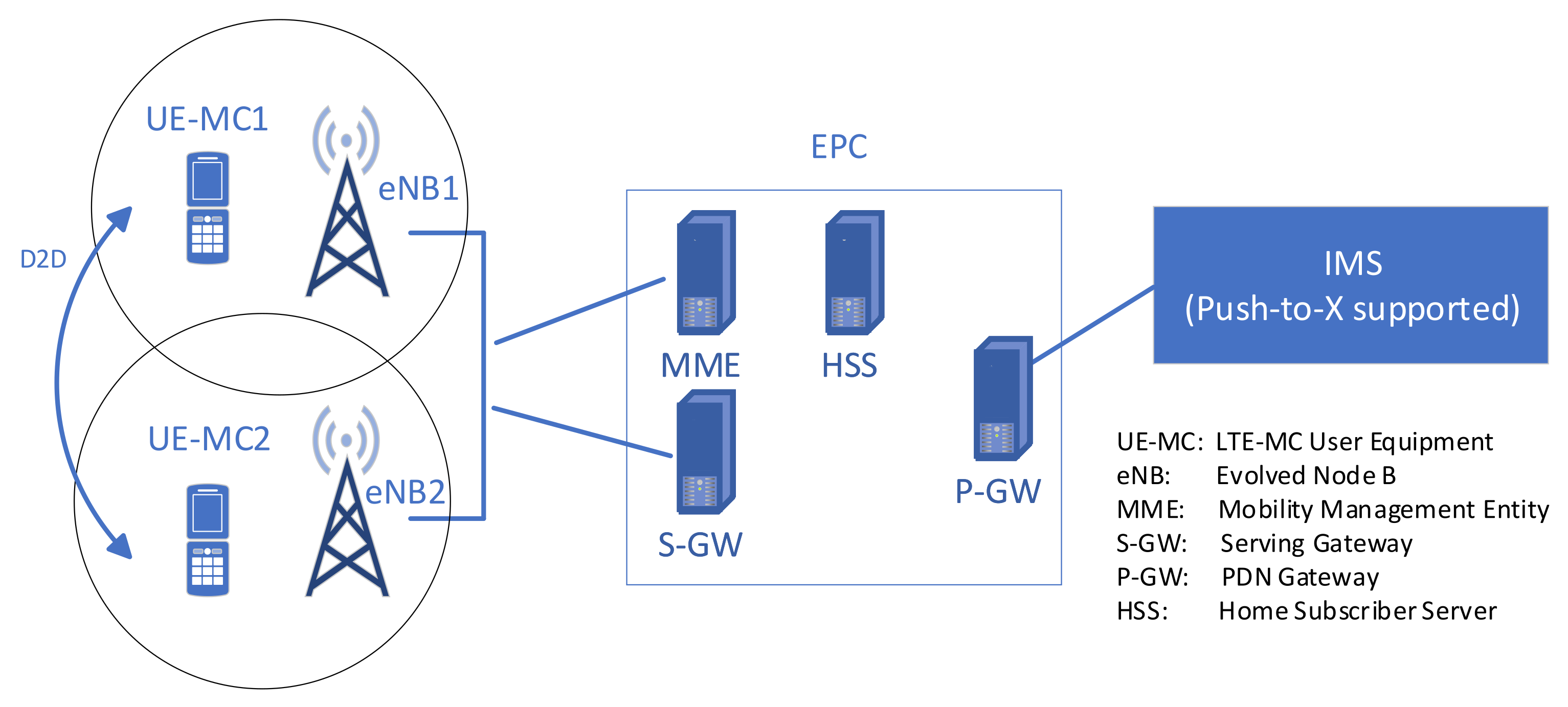
  • Provide MCS services to support rescue teams. This is so far the role of solutions, such as TETRA (narrowband) and recently-designed LTE-MC (broadband). In such a solution, the MCS provides voice, short message and data transmission to a small group of users of a dedicated network. In LTE-MC, multimedia communication is allowed due to high bandwidth and the use of a flexible platform (IP Multimedia Subsystem (IMS)).
  • Provide basic communication services to persons in the impacted area. It assumes the use of battery-powered commercial terminals (i.e., smartphones).
  • Provide backup software platforms to solutions that should be working despite the lack of support from infrastructure-based service platforms—for example, processing data from IoT sensors, control of utilities, road traffic, Smart City solutions, Supervisory Control Furthermore, Data Acquisition (SCADA) systems, etc. Adding an ad hoc service platform is not supported by TETRA nor LTE-MC.
The first requirement means that a proprietary radio technology has to be used between the UAV and the GCS, and the autonomy of flights is much more critical than in Scenario 1. This is not a substantial limitation, as many UAVs currently available come with a proprietary radio control solution. The second functionality of Scenario 2 is already described in Scenario 1, and in Scenario 2, it behaves similarly. The only difference is the (potential) lack of communication infrastructure-based networks provide.
The third and fourth functionalities require a more sophisticated approach. It lies in substituting ‘core’ functions of a network that may have wired or wireless terminals (LTE Machine Type Communication (LTE-M), Narrowband Internet of Things (NB-IoT), Long Range Wide Area Network (LoraWAN), LTE, WiFi, etc.). In the case of wired solutions, the robotic and delivery UAVs may be used to make some temporary repair of the infrastructure if direct human or other robot access is impossible. For example, in such a case, a bespoke UAV can be used for fast fibre deployment in an ‘over-the-ground’ manner. However, this paper will focus on a wireless solution because UAVs may play a much more critical role in such a case. To that end, UAVs can be used to create temporary wireless solutions for the wireless technology needed.
For this purpose, we need portable base stations with computing capabilities and mechanisms that provide interconnection of the wireless terminals of the solution to a platform (typically, such solutions use a client-server approach, and this also concerns Voice over IP (VoIP) or multimedia systems). A similar approach has already been used in Scenario 1. Still, in the mentioned case, there can be a need for more radio interfaces to be supported and also the addition of a platform that can interact with the appropriate terminals.
Both scenarios come with two kinds of problems. The first one deals with the necessity of developing a procedure for MCS deployment in a specific area. Thus far, no such procedures have been defined. The second problem is linked to the ad hoc deployment of MCS service platform.

5. VMCS Concept

This section will present the VMCS concept. The concept is based on:
  • The analysis of the services offered by TETRA and LTE-MC discussed in Section 2, as well as shortcomings of the technologies. In both cases, the set of services is predefined. Such an approach is relatively simple but has two drawbacks. Foremost, it does not allow using commercial terminals of wireless networks not supporting LTE-MC, for example, LTE/WiFi smartphones. Using such terminals is of premium importance in the case of disasters as it allows for establishing communication with any user of the commercial mobile network via MCS without using dedicated MCS terminals. The second problem is the necessity of supporting by MCS the existing IoT or SCADA solutions that lost connectivity to their service platforms. Both mentioned solutions provide no such support nor support for programmability.
  • The analysis of the concepts concerning the use of UAVs as flying communication nodes (or networks) with computing capabilities presented in Section 3. The UAV transportation and endurance capabilities enable to use them as can be used for quick provisioning of connectivity on a relatively large area.
  • The analysed in Section 4 concepts that propose the use of UAV computing capabilities, typically marked as edge computing or MEC.
  • Analysis of the two scenarios presented in Section 4 shows that, in some cases, MCS can be a part of a larger networking/computing solution or can be deployed on an island basis. The second case raises issues of management and orchestration of ad hoc deployed MCS.
To solve some of the above-mentioned issues, the VMCS approach introduces the following novelties:
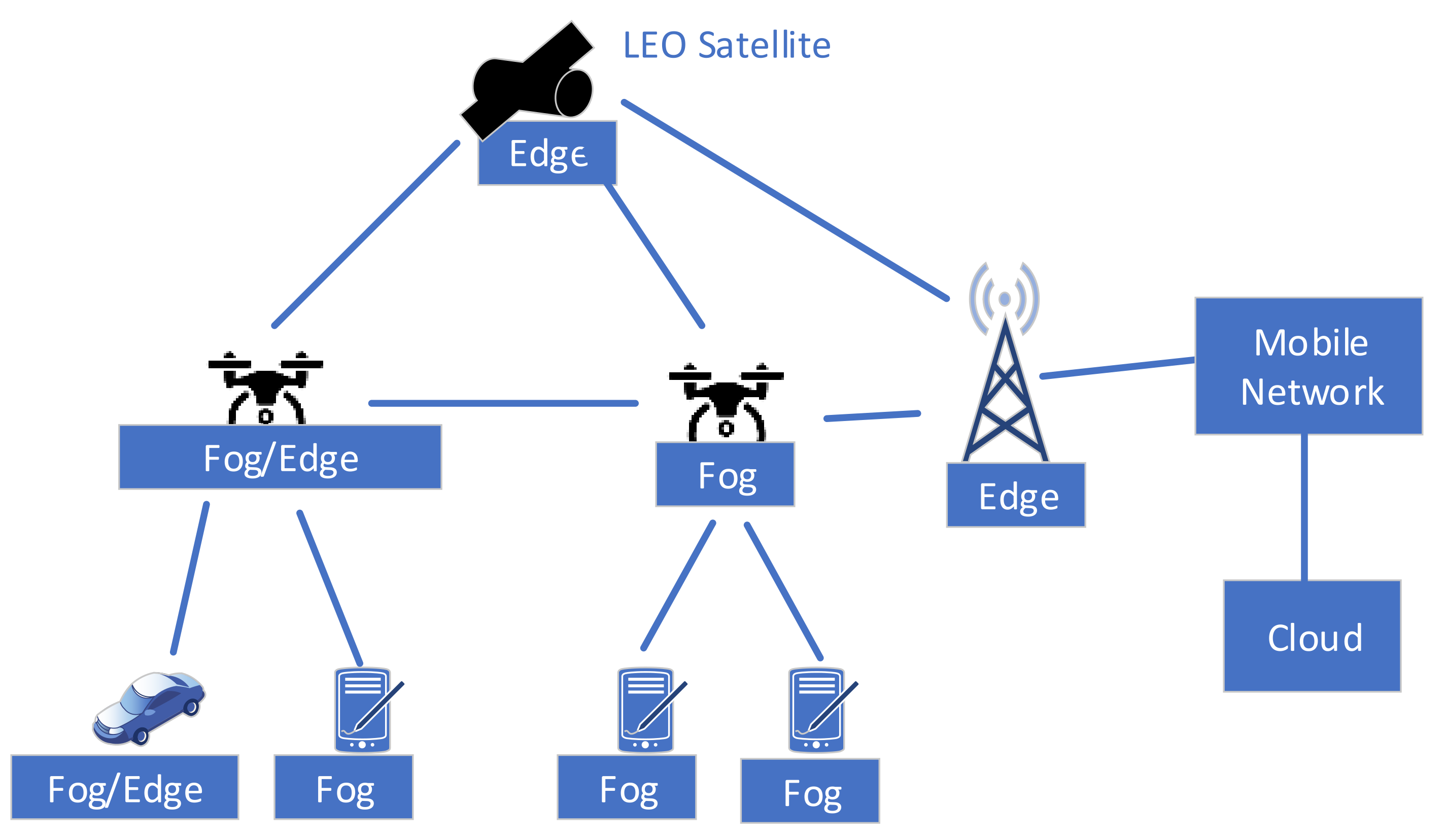
  • Uses a combined Fog/Edge/Cloud approach, i.e., exploits computing capabilities of all system nodes, including terminals. Due to Fog, the use of all system resources is maximised, and terminals can be dynamically adapted to service needs (there is no need to make dedicated terminals, commercial smartphones can be a part of the system).
  • Uses distributed, combined Fog/Edge/Cloud orchestration with redundancy that is needed in an unreliable, distributed computing environment.
  • Exploits the mobility of UAVs as a part of the orchestration.

5.1. VMCS Foundations

In the last decade, cloud technologies began to be used not only for the implementation of service platforms but also for the virtualisation of network functions, i.e., the implementation of distributed networking solutions atop the virtualised infrastructure. The approach allows for deploying in-software-made networking solutions that can be combined with services. The description of network virtualisation concepts and the benefits of the technology is out of the scope of this paper. However, with some modifications, network and service virtualisation can be exploited for a new generation of MCS. Thus far, such a solution has not been yet proposed except the use of Fog for natural disaster management [48], limited to real-time IoT applications only.
The Fog computing infrastructure assumes that nearly all network physical nodes (including terminals, routers, base stations and UAVs) provides computing capabilities; however, their resources can be constrained. Usually, the term cloudlet is used to describe such a small-scale data centre used for Fog [49]. In most Fog approaches, the Fog is only part of the solution, and the computing infrastructure is split into Fog resources (micro data centres and cloudlets), Edge resources (mini data centres) and Cloud (large data centres). In VMCS, the following nodes with computing capabilities can be identified:
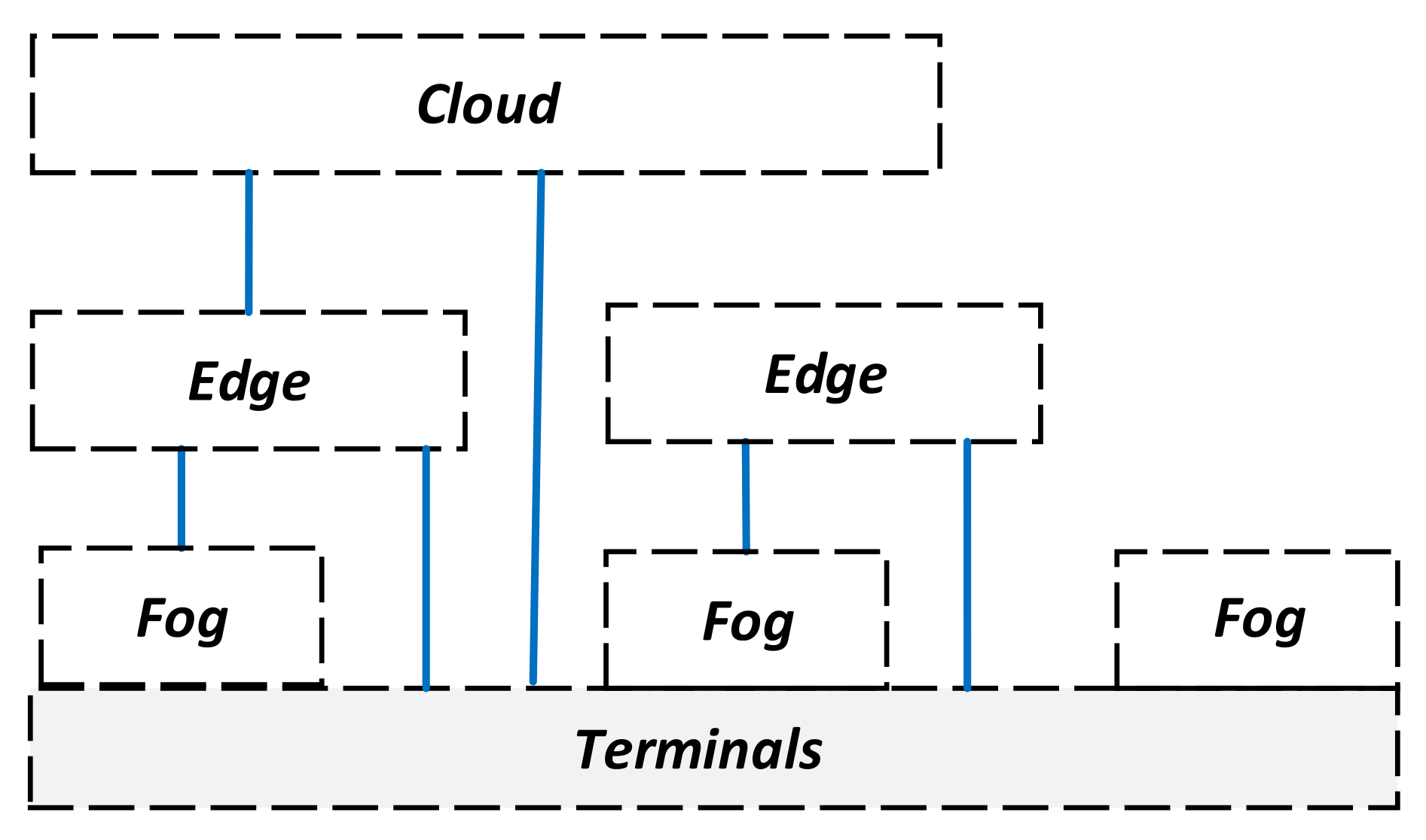
  • Terminal nodes. VMCS end-users operate such nodes. Some may be dedicated to VMCS, whereas others are just commercial terminals. Most have cloudlets; however, vehicular terminals may provide mini data centres.
  • Edge nodes are nodes between the terminals and the core part of the network. They typically may have mini data centres.
  • Core nodes. These nodes typically are connected to a reliable infrastructure and clouds by high bit rate links. Their functions can be implemented using Cloud. In Scenario 2 (Section 4), such components may not exist, and the Edge nodes take their role.
In VMCS, a node may belong to Fog or Edge category depending on their computing capability and stability of resources, as Edge and Fog use different orchestrators tailored to these properties. This is shown in Figure 4.

5.2. VMCS Orchestration

The proposed VMCS orchestration is hierarchical with Cloud-based orchestration at the highest level, Edge-based orchestration and the middle level and Fog orchestration based at the lowest level. The orchestration architecture is redundant—all orchestrators should be able to work independently (i.e., the VMCS may have the Edge orchestrator only); however, in the case they are all present, they should cooperate to achieve their goal. This is illustrated in Figure 5.

5.2.1. VMCS Cloud Orchestration

Typically, the ETSI MANO [50] approach is used for network and orchestration in Clouds. It allows for the programmatic creating of a network in a distributed Cloud environment using virtual machines or containers [51]. Such networks consist of components of Virtual Network Function (VNF) or Cloud-native Network Function (CNF). The MANO orchestrator is responsible for the so-called life cycle management of created software networks (their installation, modification and uninstalling) and for the dynamic allocation of virtual infrastructure (called NFV Infrastructure (NFVI)) resources, which consists of computing resources, connectivity and memory.
The MANO orchestration is already a part of the 5G network, for which it is responsible for creating virtual networks called network slices [52]. Unfortunately, the MANO solution cannot be the only orchestration solution in VMCS. This solution is highly centralised (typically, one MANO orchestrator is used for the whole network) and requires reliable, high-bitrate communication links and a stable infrastructure that usually comprises large and reliable data centres, the resource pool of which is typically slow-changing over time.
The distributed Cloud infrastructure used by MANO has fibre-based connectivity typically and can also suffer in case of power grid failure or disaster (broken fibres, etc.). However, as long as the Clouds and their connectivity function, the Clouds orchestrated using ETSI MANO or Kubernetes should be part of VMCS with minor modifications. These modifications concern cooperation with Edge and Fog that should be done and Cloud OSS/BSS level.

5.2.2. VMCS Edge Orchestration

The Edge has a special meaning in VMCS. It generally has more resources than Fog and is more reliable Fog. Fog and Edge virtualisation in MCS should consider constrained and dynamic resources and the lack of stable links that can be used for the management and operations. This means that the orchestration should be able to cope with dynamically available and mobile resources, such as UAVs, and may request deployment of needed nodes in certain locations in order to achieve the requested MCS functionality (coverage, service supporting nodes, etc.). For Edge (and Fog) a lightweight and relatively simple virtualization technology should be used (for example containers, ClickOs [53], OSGi/JADE [54] or mobile agents’ [55]). VMCS has some specific requirements concerning Edge orchestration, which have to be considered:
  • Dynamic Edge infrastructure. There is a need to efficiently collect, process and maintain information about the state of the VMCS Edge infrastructure. It includes operations for discovering new nodes and links, their geo-position, evaluating nodes’ battery state and amount of offered resources and links, providing nodes’ and links’ reputation evaluation (in terms of reliability) and predicting resources status. The information about the resource state (offered and consumed resources) should be, for reliability, kept in a lightweight, distributed database.
  • Distributed and reliable management and orchestration of the Edge. To cope with unreliability, there is a need for using multiple, synchronised copies of functional entities involved in orchestration. It implies a definition of an orchestrator that can cope with vanishing orchestrator functions—when one of them disappears (due to lack of energy or communication link breakdown), the backup function should conclude the management or orchestration task. Moreover, the orchestration commands should have multiple copies transferred using a disjoint path (if possible) to cope with the unreliability of links. Some network nodes should be used as relays for management and orchestration messages, with additional mechanisms ensuring their reliable delivery.
  • Exploitation of Edge nodes mobility: In VMCS, some nodes, particularly UAVs, are mobile. The Edge orchestrator should cope with the nodes’ mobility and should be able to exploit it—if possible, the orchestrator should define their optimal position and steer them to achieve this position.
  • Edge service templates specifics. The service template (aka blueprint) of VMCS needs to have a different form than the templates used by the MANO orchestrator. It should allow for the implementation of DTN [56] based services, i.e., the temporary absence of a link should be accepted as a normal state and information collected by a node should be transferred to another node when connectivity is restored. The template should include duplicated nodes/functions (in case of failure or node disconnection), a specific mechanism for delivery and delivery confirmation of sent messages. More details about VMCS services implementation will be provided in the subsequent subsection.
The orchestration components of VMCS Edge can be orchestrated by the Cloud orchestrator or by themselves. A high-level sketch of the proposed VMCS EDGE orchestration architecture is presented in Figure 6. It is composed of the following entities that are implemented using Edge resources:
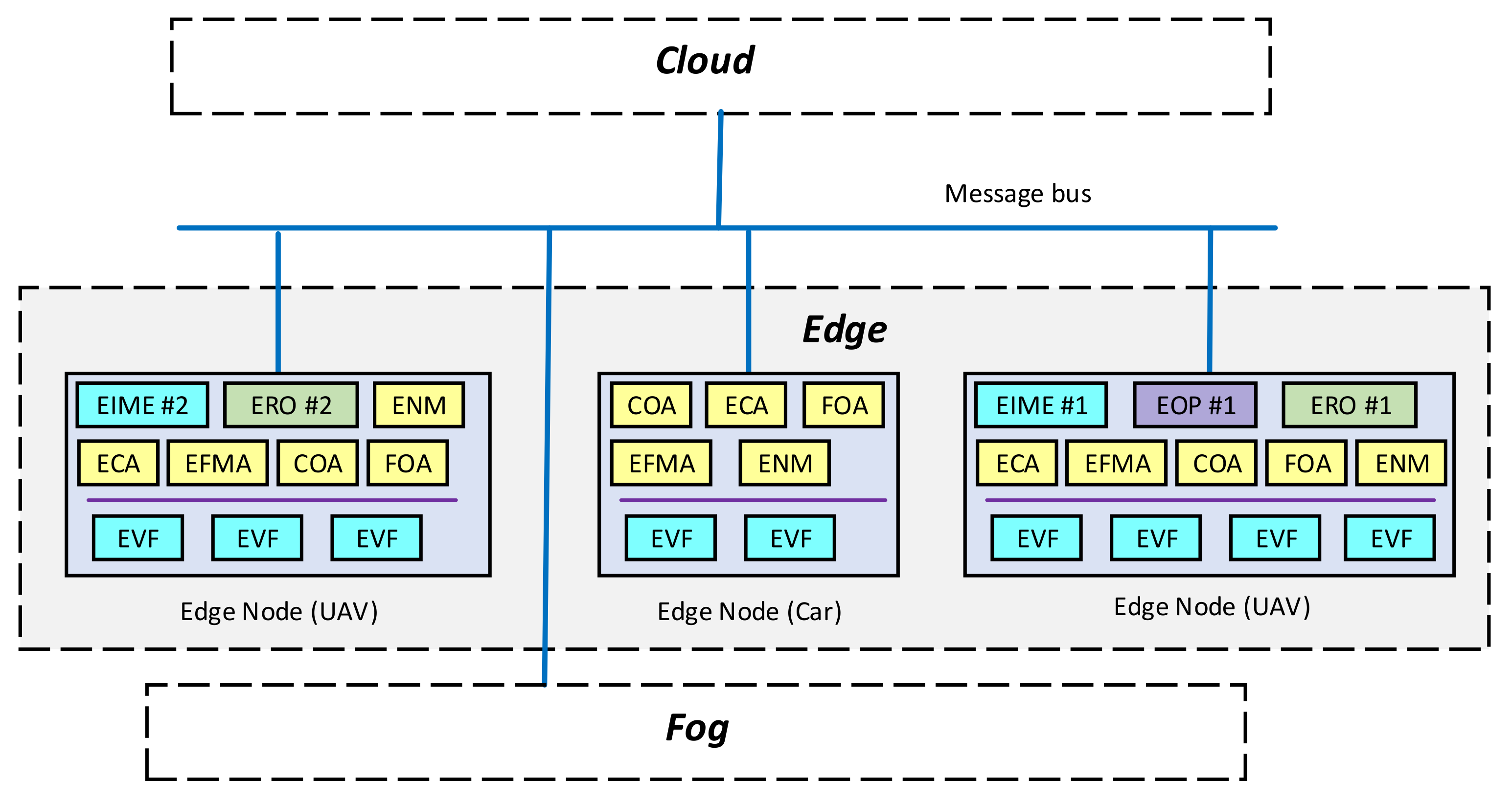
  • Edge Node Manager (ENM). This is a component of each Edge node. It performs overall management of the node and, via COA and FOA, interacts with Fog and Cloud orchestrators. It discovers entities of the Edge orchestration system.
  • Fog Orchestration Agent (FOA). This is a component of each Edge node. It is involved in Fog orchestration (if applicable), playing a master role. It monitors the Fog infrastructure and drives Fog orchestration.
  • Cloud Orchestration Agent (COA). This is a component of each Edge node. It takes orders from the Cloud orchestrator (if applicable) regarding Edge orchestration.
  • Edge Connectivity Agent (ECA). This is a component of each Edge node that is responsible for the reliable delivery of orchestration and management messages between the Edge nodes.
  • Edge Functions Migration Agent (EFMA). This is a component of the distributed Edge orchestrator that is responsible for decisions regarding migration Edge Virtual Functions (EVF) and functions of the distributed orchestrator, i.e., VOP, ERO and EIME. For the sake of reliability, multiple instances of EFMA are allowed.
  • Edge Infrastructure Monitoring Entities (EIME). EIME is a set of entities that keeps the information about the infrastructure resources’ state and location. They also try to predict the resource state based on historical data. In the case of mobile Edge nodes, EIME obtains their position, and at the request of ERO, can change it. For the sake of reliability, there are multiple synchronised EIME instances.
  • Edge Reliable Orchestrator (ERO). This logical entity is responsible for the orchestration process. It interacts with EIME to obtain information about the state of resources. Based on the VMCS service template analysis and the state of resources, it deploys Edge Virtual Functions (EVFs). For reliability, there are multiple synchronised ERO instances in the system.
  • Edge Virtual Functions (EVFs). These functions implement the required VMCS services in the Edge and are part of the service template. Please note that part of the Service can be implemented in a Fog and/or in a Cloud.
  • Edge Operator Portal (EOP). The Edge Operator Portal is the functionality that allows the operator to interact with the Edge platform. It can be used to monitor Edge status and to enforce some Edge node actions, including the definition of mobile nodes’ position. Logically it is a single entity but, for the sake of reliability, can be implemented as a set of multiple, synchronised components with assigned priorities of operations.
It is assumed that for interactions between components a message bus will be used. The VMCS solution has to use some mechanisms that provide reliable services implemented in unreliable environments. They are responsible for intelligent management of the template instance, implementing the idea of self-managed network slices [57]. Their functionalities include self-configuration of a service/slice, reconfiguration of a service/slice, healing of the service, optimising service behaviour due to mobility of nodes and triggering an orchestration event when needed.
Each of the services assesses the quality of the infrastructure resources and takes decisions regarding the placement of service functions. The functions’ placement is complemented by the application-level routing that improves the connectivity reliability between them. The reliability of services is also provided by having replicas of service functions and databases.
Each service should be written that way that it can work autonomously with marginal interaction with other services, even if the network is partitioned. The ‘Service Reliability Mechanisms’ can be different for each service, as each service node may have different requirements. It is proposed to separate resource orchestration from service orchestration and built-in the service orchestration capabilities in each of the deployed services.
As already discussed, a UAV may play multiple roles in MCS. All the UAV roles described in Scenarios 1 and 2 apply to VMCS. In VMCS, however, a UAV may play an additional function; a UAV can transport the role of a ‘mobile server’. Such a ‘mobile server’ is an infrastructure element that provides computing and storage capabilities (combined with connectivity) that can be added to the infrastructure resources to deploy the required application(s). Please note that UAV functionalities can be pre-programmed before the flight.

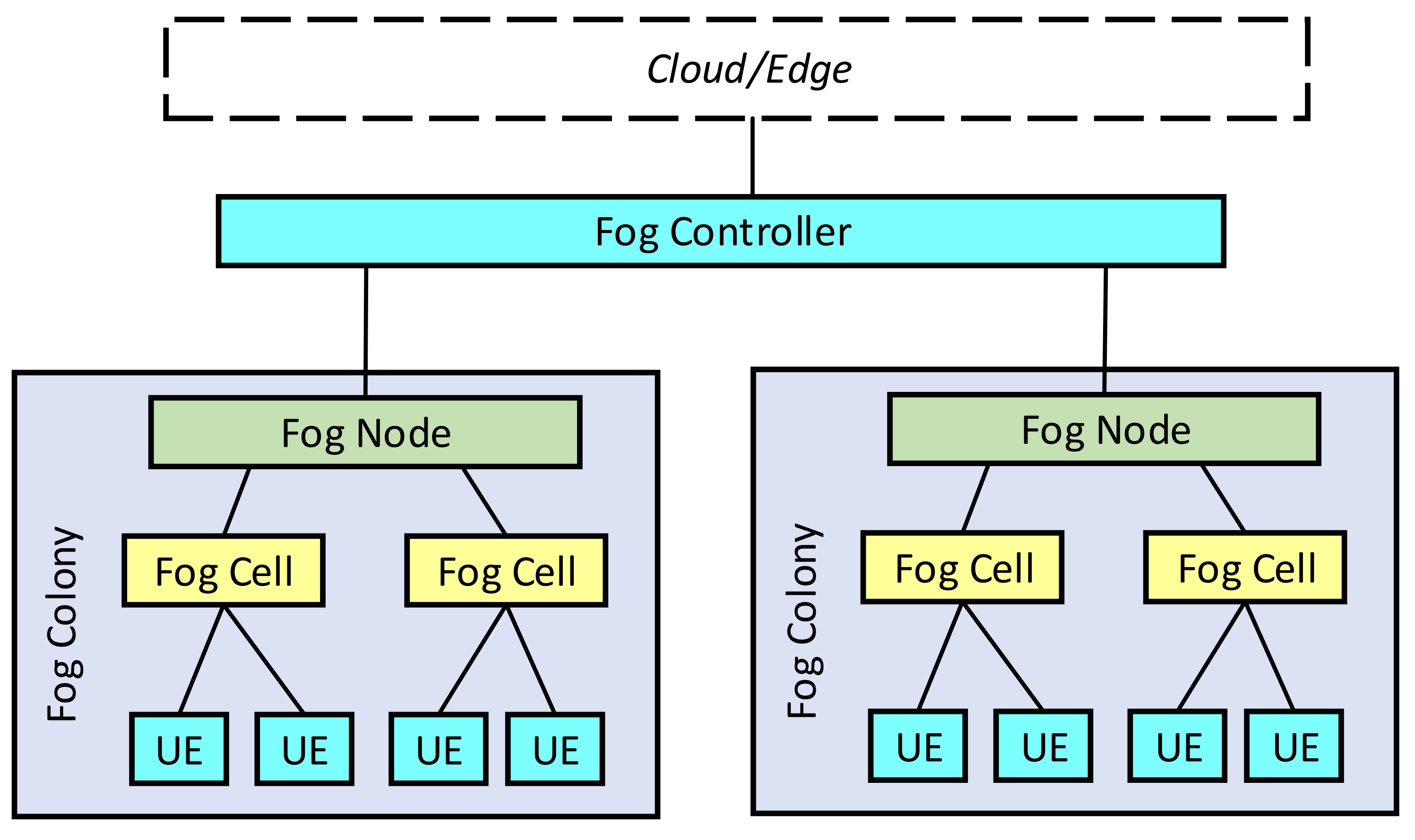
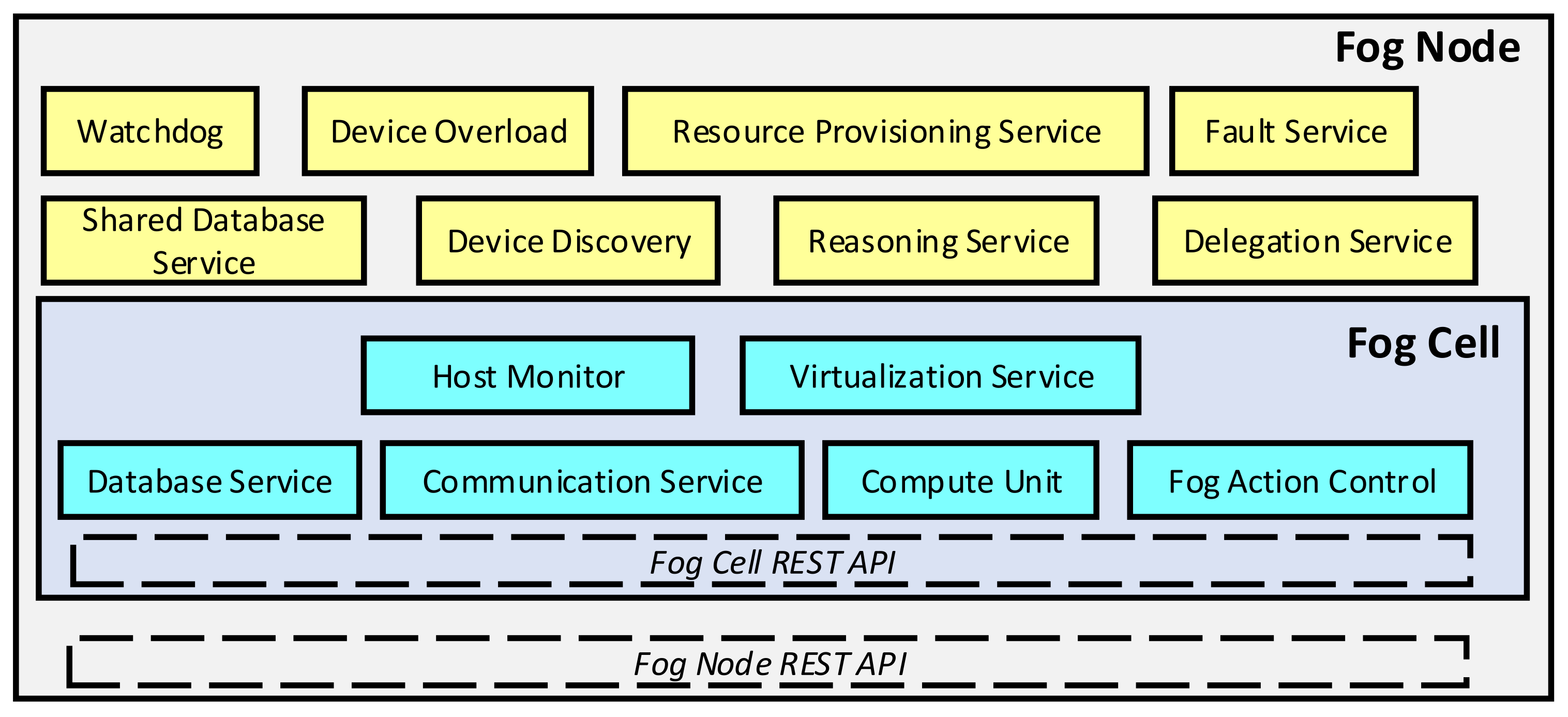
5.2.3. VMCS Fog Orchestration

The Fog-specific orchestration issues, mostly in the context of IoT orchestration, have already been addressed by some papers. All fog orchestrators consider constrained resources and high unreliability of nodes, a need for resource and service discovery, the possibility of quick topology changes and continuous system monitoring and adaptation. In [58,59], a survey on Fog orchestration is provided. The mentioned paper describes the OpenFog Reference Architecture (OpenFog RA) designed by the OpenFog Consortium [60].
The architecture is based on several pillars that include orchestration scalability, openness, autonomy (failure resistance), programmability and reliability. One of the key features of OpenFog RA is a hierarchy, which helps in the federation of multiple Fog subsystems (domains). The paper also mentions SORTS and SOAFI orchestrators. The SORTS (Supporting the Orchestration of Resilient and Trustworthy Fog Services) orchestrator is composed of the Communication Manager that handles the communication between different Fog orchestrators, the Resource Manager that monitors the infrastructure resources usage, Planner Mechanisms that places and schedule the system processes, Service Discovery component that provides information about services, the Status Monitor that monitors the behaviour of the system and the Optimisation Mechanisms that optimise the performance of the system.
The SORTS infrastructure is split between the IoT Level, Fog level and the Cloud level. IoT level (the lowest level, group of terminals) allows for the creation of IoT clusters that cooperate. Another approach, SOAFI (Service Orchestrator Architecture for Fog-enabled Infrastructure), uses a centralised Fog orchestrator. It consists of functions related to resources (discovery, catalogue and allocation) and services (service catalogue and services management functionality). Each SOAFI node (cloudlet) has a Fog Orchestration Agent, which interacts with the orchestrator. Some SORTS and SOAFI mechanisms are used in VMCS orchestration.
Fog service placement is an optimisation problem that can be solved using different optimisation algorithms and AI. An example approach that uses the genetic algorithm to solve the problem is presented in [61,62], another approach that uses constraint programming is described in [63] and a survey of Fog service placement issues is presented in [64] and combined service placement in Cloud and Fog is described in [65]. For the Fog of VMCS, we decided to use the FogFrame framework described in [66]. The concept provides generic mechanisms needed for Fog orchestration and is in line with OpenFog recommendations. The overall FogFrame architecture is depicted in Figure 7.
The FogFrame architecture is composed of the following entities:
  • Fog Cells represent virtual resources of UEs (also the IoT devices) that Fog services use.
  • Fog Nodes are specific Fog Cells that act as access points for other Fog cells and provide connectivity with other Fog Nodes.
  • Fog Colonies act as micro data centres composed of distributed resources that consist of Fog Cells and their terminals connected to a Fog Node. Each Fog colony has one Head Fog Node.
  • The Fog Controller is used for the discovery of new resources. It provisions resources in the Edge or Cloud that support Fog operations. If Cloud or Edge is available, the Fog controlled can be placed in the Edge or Cloud, respectively.
The communication between Fog Colonies is provided via a dedicated node called Head Fog Node. The internal architecture of a FogFrame Node and Cell is depicted in Figure 8. More details describing this approach can be found in [66].

5.2.4. Remarks on VMCS Orchestration

In VMCS, different orchestrators have to be used to cope with different sizes of data centres, their reliability and eventual mobility. To solve the problem, we proposed to use three different orchestrators. Due to the specifics of MCS, not all of them will be present in all use cases. This implies autonomicity of Fog, Edge and Cloud orchestration and cooperation between different orchestrators as long as they are available. This means that, in some cases, the service template can be split between different orchestrators; in another case, the service has to be fully implemented in a Fog or Edge or Cloud. This challenges cooperation between different orchestrators and service template split combined with service placement. We left this original and complicated topic for further study.

6. Conclusions

In this paper, we presented the usage of UAVs in virtualized mission-critical solutions. First, we briefly described the most popular narrowband mission-critical solution, i.e., TETRA, and the ongoing work on the LTE-MC, which is seen as the fundamental solution for mission-critical broadband communications. Later, we provided a short characteristic of UAVs, considering their usage in MCS. We also listed UAV approaches to enhancing connectivity and computing services. To formulate additional requirements, we described two scenarios of exploitation of UAVs in MCS.
Finally, we proposed and described an innovative mission-critical solution, VMCS, that leverages network virtualization and the orchestration of resources of all system nodes, including end-user terminals and UAVs. TheVMCS solves the communication problem of users with no dedicated MCS terminals. It provides programmable connectivity and a service platform that can support services that suffer from the lack of support by the infrastructure (lack of access to clouds, etc.). The proposed approach has its price, namely complex orchestration and service platforms. Both platforms cope with unreliable infrastructure with constrained resources. The orchestration additionally exploits the position and mobility of the nodes that are part of the infrastructure, particularly concerning UAVs.
The orchestration of unreliable resources using unreliable orchestration platforms is a new challenge, and thus far, no solution has been proposed. This paper outlines the problem and draws an Edge orchestration architecture able to cope with such a case. The benefits of virtualization combined with UAV usage for MCS justify the complex orchestration of VMCS. The paper outlines the proposed concept; however, much more work is needed on the details of the proposed architecture and intelligent algorithms for resource monitoring, disruptive connectivity handling and computing/storage node placement. These are the goals of our future works.

Author Contributions

Conceptualization, S.K., P.C. and K.S.; methodology, S.K., P.C. and K.S.; writing—original draft preparation, S.K., P.C. and K.S.; writing—review and editing, S.K.; funding acquisition, S.K. All authors have read and agreed to the published version of the manuscript.

Funding

This research was partly funded by Warsaw University of Technology under research grant IDUB/VMC no. 45.010301.

Institutional Review Board Statement

Not applicable.

Informed Consent Statement

Not applicable.

Data Availability Statement

Not applicable.

Conflicts of Interest

The authors declare no conflict of interest.

Abbreviations

The following abbreviations are used in this manuscript:
3GPP3rd Generation Partnership Project
5G5th Generation
5GC5G Core
BVLOSBeyond Visual Line of Sight
C2Command and Control
CNFCloud-native Network Function
CUCentralised Unit
DTNDisruption Tolerant Networking
DUDistributed Unit
EPCEvolved Packet Core
ETSIEuropean Telecommunications Standards Institute
EUEuropean Union
GCSGround Control Station
GPSGlobal Positioning System
HAPSHigh Altitude Platform System
ICTInformation and Communications Technology
IMSIP Multimedia Subsystem
IoTInternet of Things
ISMIndustrial, Scientific and Medical
LEOLow Earth Orbit
LoraWANLong Range Wide Area Network
LTELong Term Evolution
LTE-MLTE Machine Type Communication
LTE-MCLTE Mission Critical
MANETMobile Ad hoc Network
MANOManagement and Orchestration
MCSMission-Critical System
MECMulti-access Edge Computing
MEOMedium Earth Orbit
MIMOMultiple Input Multiple Output
NASANational Aeronautics and Space Administration
NB-IoTNarrowband Internet of Things
NFNetwork Function
NFVNetwork Function Virtualisation
NFVINFV Infrastructure
NRNew Radio
NSNetwork Slicing
NTNNon-Terrestrial Network
P25Project 25
POTSPlain Old Telephone Service
PPDRPublic Protection & Disaster Relief
ProSeProximity-based Services
QoSQuality of Service
RRHRemote Radio Head
SBAService-Based Architecture
SCADASupervisory Control And Data Acquisition
SMSShort Message Service
TDMATime-Division Multiple Access
TEDSTETRA Enhanced Data Service
TETRATerrestrial Trunked Radio
TETRAPOLTerrestrial Trunked Radio Police
UASUnmanned Aircraft System
UAVUnmanned Aerial Vehicle
UEUser Equipment
UTMUnmanned Aircraft Systems Traffic Management
V2XVehicle to Everything
VLOSVisual Line of Sight
VMCSVirtualized Mission Critical System
VNFVirtual Network Function
VoIPVoice over IP
VTOLVertical Take-Off and Landing
WiFiWiFi

References

  1. ETSI EN 300 392-1; Terrestrial Trunked Radio (TETRA); Voice Plus Data (V+D); Part 1: General Network Design. ETSI: Sophia Antipolis, France, 2009.
  2. PAS 0001-1-1; TETRAPOL Specifications; Part 1: General Network Design; Part 1: Reference Model. TETRAPOL: Bois d’Arcy, France, 1999.
  3. TIA-102.AABA-C; Project 25 Trunking Overview Digital Radio Technical. TIA: Arlington, VA, USA, 2019.
  4. 3GPP TE 23.002; Technical Specification Group Services and System Aspects; Network architecture (Release 15). ETSI: Sophia Antipolis, France, 2018.
  5. 3GPP TS 23.179; Functional Architecture and Information Flows to Support Mission-Critical Communication Services. ETSI: Sophia Antipolis, France, 2017.
  6. Fragkiadakis, A.; Askoxylakis, I.; Tragos, E.; Verikoukis, C. Ubiquitous Robust Communications for Emergency Response using Multi-Operator. EURASIP J. Wirel. Commun. Netw. 2011. [Google Scholar] [CrossRef][Green Version]
  7. 3GPP TS 23.246; Multimedia Broadcast/Multicast Service (MBMS); Architecture and Functional Description. ETSI: Sophia Antipolis, France, 2022.
  8. 3GPP TS 24 481; Mission Critical Services (MCS) Group Management; Protocol Specification. ETSI: Sophia Antipolis, France, 2019.
  9. 3GPP TS 23.228; IP Multimedia Subsystem (IMS), Stage 2. ETSI: Sophia Antipolis, France, 2021.
  10. 3GPP TS 23.303; Proximity-Based Services (ProSe); Stage 2. ETSI: Sophia Antipolis, France, 2021.
  11. 3GPP TS 22.179; Mission Critical Push to Talk (MCPTT); Stage 1. ETSI: Sophia Antipolis, France, 2022.
  12. 3GPP TS 22.280; Mission Critical Services Common Requirements (MCCoRe); Stage 1. ETSI: Sophia Antipolis, France, 2022.
  13. 3GPP TS 22.281; Mission Critical (MC) Video. ETSI: Sophia Antipolis, France, 2022.
  14. 3GPP TS 22.282; Mission Critical (MC) Data. ETSI: Sophia Antipolis, France, 2022.
  15. Kaleem, Z.; Yousaf, M.; Qamar, A.; Ahmad, A.; Duong, T.Q.; Choi, W.; Jamalipour, A. UAV-Empowered Disaster-Resilient Edge Architecture for Delay-Sensitive Communication. IEEE Netw. 2019, 33, 124–132. [Google Scholar] [CrossRef]
  16. 3GPP TS 23.180; Mission Critical Services Support in the Isolated Operation for Public Safety (IOPS) Mode of Operation. ETSI: Sophia Antipolis, France, 2022.
  17. 3GPP TR 23.744; Study on Location Enhancements for Mission-Critical Services. ETSI: Sophia Antipolis, France, 2020.
  18. 3GPP TS 23.501; System Architecture for the 5G System (5GS); Stage 2 (Release 17). ETSI: Sophia Antipolis, France, 2022.
  19. 3GPP TS 28.530; Management and Orchestration; Concepts, Use Cases and Requirements. ETSI: Sophia Antipolis, France, 2021.
  20. 3GPP TS 23.289; Mission Critical Services over 5G Systems. ETSI: Sophia Antipolis, France, 2022.
  21. Lin, X.; Rommer, S.; Euler, S.; Yavuz, E.A.; Karlsson, R.S. 5G from Space: An Overview of 3GPP Non-Terrestrial Networks. IEEE Commun. Stand. Mag. 2021, 5, 147–153. [Google Scholar] [CrossRef]
  22. Gupta, A.; Afrin, T.; Scully, E.; Yodo, N. Advances of UAVs toward Future Transportation: The State-of-the-Art, Challenges, and Opportunities. Future Transp. 2021, 1, 326–350. [Google Scholar] [CrossRef]
  23. Watts, A.C.; Ambrosia, V.G.; Hinkley, E.A. Unmanned Aircraft Systems in Remote Sensing and Scientific Research: Classification and Considerations of Use. Remote Sens. 2012, 4, 1671–1692. [Google Scholar] [CrossRef][Green Version]
  24. Eisenbeiß, H. UAV Photogrammetry. Ph.D. Thesis, ETH Zurich, Zurich, Switzerland, 2009. [Google Scholar]
  25. Qi, S.; Wang, F.; Jing, L. Unmanned aircraft system pilot/operator qualification requirements and training study. MATEC Web Conf. 2018, 179, 03006. [Google Scholar] [CrossRef][Green Version]
  26. Jeziorska, J. UAS for Wetland Mapping and Hydrological Modeling. Remote Sens. 2019, 11, 1997. [Google Scholar] [CrossRef][Green Version]
  27. 3GPP TS 22.125; Unmanned Aerial System (UAS) Support in 3GPP. ETSI: Sophia Antipolis, France, 2022.
  28. Thiels, C.A.; Aho, J.M.; Zietlow, S.P.; Jenkins, D.H. Use of Unmanned Aerial Vehicles for Medical Product Transport. Air Med. J. 2015, 34, 104–108. [Google Scholar] [CrossRef]
  29. Zipline. Zipline Delivers 1 Million COVID-19 Vaccines in Ghana. Available online: https://www.flyzipline.com/press/zipline-delivers-1-million-covid-19-vaccines-in-ghana (accessed on 27 May 2022).
  30. Wing. Available online: https://wing.com/ (accessed on 1 June 2022).
  31. FlyingBasket Company Webpage. Available online: https://flyingbasket.com/ (accessed on 1 June 2022).
  32. Zeng, Y.; Wu, Q.; Zhang, R. Accessing From the Sky: A Tutorial on UAV Communications for 5G and Beyond. Proc. IEEE 2019, 107, 2327–2375. [Google Scholar] [CrossRef][Green Version]
  33. 3GPP TS 23.256; Support of Uncrewed Aerial Systems (UAS) Connectivity, Identification and Tracking; Stage 2. ETSI: Sophia Antipolis, France, 2022.
  34. The Concept of Operations for European Unmanned Traffic Management (UTM) Systems (CORUS). Available online: https://www.sesarju.eu/projects/corus (accessed on 31 May 2022).
  35. Tomaszewski, L.; Kołakowski, R.; Dybiec, P.; Kukliński, S. Mobile Networks’ Support for Large-Scale UAV Services. Energies 2022, 15, 4974. [Google Scholar] [CrossRef]
  36. Viana, J.; Cercas, F.; Correia, A.; Dinis, R.; Sebastião, P. MIMO Relaying UAVs Operating in Public Safety Scenarios. Drones 2021, 5, 32. [Google Scholar] [CrossRef]
  37. Bekkouche, O.; Samdanis, K.; Bagaa, M.; Taleb, T. A Service-Based Architecture for Enabling UAV Enhanced Network Services. IEEE Netw. 2020, 34, 328–335. [Google Scholar] [CrossRef]
  38. Alsamhi, S.H.; Shvetsov, A.V.; Kumar, S.; Shvetsova, S.V.; Alhartomi, M.A.; Hawbani, A.; Rajput, N.S.; Srivastava, S.; Saif, A.; Nyangaresi, V.O. UAV Computing-Assisted Search and Rescue Mission Framework for Disaster and Harsh Environment Mitigation. Drones 2022, 6, 154. [Google Scholar] [CrossRef]
  39. Cheng, N.; Xu, W.; Shi, W.; Zhou, Y.; Lu, N.; Zhou, H.; Shen, X. Air-ground integrated mobile edge networks: Architecture, challenges, and opportunities. IEEE Commun. Mag. 2018, 56, 26–32. [Google Scholar] [CrossRef][Green Version]
  40. Alsamhi, S.H.; Shvetsov, A.V.; Kumar, S.; Hassan, J.; Alhartomi, M.A.; Shvetsova, S.V.; Sahal, R.; Hawbani, A. Computing in the Sky: A Survey on Intelligent Ubiquitous Computing for UAV-Assisted 6G Networks and Industry 4.0/5.0. Drones 2022, 6, 177. [Google Scholar] [CrossRef]
  41. Yazid, Y.; Ez-Zazi, I.; Guerrero-González, A.; El Oualkadi, A.; Arioua, M. UAV-Enabled Mobile Edge-Computing for IoT Based on AI: A Comprehensive Review. Drones 2021, 5, 148. [Google Scholar] [CrossRef]
  42. Dicandia, F.A.; Fonseca, N.; Bacco, M.; Mugnaini, S.; Genovesi, S. Space-Air-Ground Integrated 6G Wireless Communication Networks: A Review of Antenna Technologies and Application Scenarios. Sensors 2022, 22, 3136. [Google Scholar] [CrossRef]
  43. Grasso, C.; Schembra, G. A fleet of MEC UAVs to extend a 5G network slice for video monitoring with low-latency constraints. J. Sens. Actuator Netw. 2019, 8, 3. [Google Scholar] [CrossRef][Green Version]
  44. Wheeb, A.H.; Nordin, R.; Samah, A.A.; Alsharif, M.H.; Khan, M.A. Topology-Based Routing Protocols and Mobility Models for Flying Ad Hoc Networks: A Contemporary Review and Future Research Directions. Drones 2022, 6, 9. [Google Scholar] [CrossRef]
  45. Siddiqui, A.B.; Aqeel, I.; Alkhayyat, A.; Javed, U.; Kaleem, Z. Prioritized User Association for Sum-Rate Maximization in UAV-Assisted Emergency Communication: A Reinforcement Learning Approach. Drones 2022, 6, 45. [Google Scholar] [CrossRef]
  46. Chen, X.; Wu, C.; Chen, T.; Liu, Z.; Zhang, H.; Bennis, M.; Liu, H.; Ji, Y. Information Freshness-Aware Task Offloading in Air-Ground Integrated Edge Computing Systems. IEEE J. Sel. Areas Commun. 2022, 40, 243–258. [Google Scholar] [CrossRef]
  47. Starlink. Available online: https://www.starlink.com/satellites (accessed on 1 June 2022).
  48. Wang, Z.; Goudarzi, M.; Aryal, J.; Buyya, R. Container Orchestration in Edge and Fog Computing Environments for Real-Time IoT Applications. arXiv 2022, arXiv:2203.05161. [Google Scholar]
  49. Satyanarayanan, M.; Bahl, P.; Caceres, R.; Davies, N. The case for vm-based cloudlets in mobile computing. IEEE Pervasive Comput. 2009, 8, 14–23. [Google Scholar] [CrossRef]
  50. ETSI GR NFV-MAN 001; Network Functions Virtualisation (NFV); Management and Orchestration; Report on Management and Orchestration Framework. ETSI: Sophia Antipolis, France, 2021.
  51. ETSI GS NFV-IFA 040; Network Functions Virtualisation (NFV) Release 4; Management and Orchestration; Requirements for Service Interfaces and Object Model for OS Container Management and Orchestration Specification. ETSI: Sophia Antipolis, France, 2020.
  52. 3GPP TS 28.533; Management and Orchestration; Architecture Framework (Release 15). ETSI: Sophia Antipolis, France, 2018.
  53. Martins, J.; Ahmed, M.; Raiciu, C.; Olteanu, V.; Honda, M.; Bifulco, R.; Huici, F. ClickOS and the Art of Network Function Virtualization. In Proceedings of the 11th USENIX Conference on Networked Systems Design and Implementation, Seattle, WA, USA, 2 April 2014. [Google Scholar]
  54. OSGI Alliance, OSGI Specifications. Available online: https://docs.osgi.org/specification/ (accessed on 1 June 2022).
  55. Lange, D.B.; Oshima, M. Seven good reasons for mobile agents. Commun. ACM 1999, 42, 88–89. [Google Scholar] [CrossRef]
  56. Caini, C.; Cruickshank, H.; Farrell, S.; Marchese, M. Delay-and disruption-tolerant networking (DTN): An alternative solution for future satellite networking applications. Proc. IEEE 2011, 99, 1980–1997. [Google Scholar] [CrossRef]
  57. Kuklinski, S.; Tomaszewski, L. DASMO: A scalable approach to network slices management and orchestration. In Proceedings of the NOMS 2018, Taipei, Taiwan, 9 July 2018. [Google Scholar]
  58. Costa, B.; Bachiega, J., Jr.; De Carvalho, L.R.; Araujo, A.P.F. Orchestration in Fog Computing: A Comprehensive Survey. ACM Comput. Surv. 2022, 55, 2. [Google Scholar] [CrossRef]
  59. Velasquez, K.; Abreu, D.P.; Assis, M.R.M.; Senna, C.; Aranha, D.F.; Bittencourt, L.F.; Laranjeiro, N.; Curado, M.; Vieira, M.; Monteiro, E.; et al. Fog orchestration for the Internet of Everything: State-of-the-art and research challenges. J. Internet Serv. Appl. 2018, 9, 14. [Google Scholar] [CrossRef][Green Version]
  60. Group OCAW. OpenFog Reference Architecture for Fog Computing; Technical Report; OpenFog Consortium: Freemont, CA, USA, 2017. [Google Scholar]
  61. Guerrero, C.; Lera, I.; Juiz, C. Evaluation and efficiency comparison of evolutionary algorithms for service placement optimization in fog architectures. Future Gener. Comput. Syst. 2019, 97, 131–144. [Google Scholar] [CrossRef]
  62. Skarlat, O.; Nardelli, M.; Schulte, S.; Borkowski, M.; Leitner, P. Optimized IoT service placement in the fog. SOCA 2017, 11, 427–443. [Google Scholar] [CrossRef]
  63. Salaht, F.A.; Desprez, F.; Lebre, A.; Prud’homme, C.; Abderrahim, M. Service Placement in Fog Computing Using Constraint Programming. In Proceedings of the 2019 IEEE International Conference on Services Computing (SCC), Milan, Italy, 8–13 July 2019; pp. 19–27. [Google Scholar] [CrossRef][Green Version]
  64. Farah, A.S.; Frédéric, D.; Adrien, L. An Overview of Service Placement Problem in Fog and Edge Computing. ACM Comput. Surv. 2020, 53, 1–35. [Google Scholar] [CrossRef]
  65. Souza, V.B.; Masip-Bruin, X.; Marín-Tordera, E.; Sànchez-López, S.; Garcia, J.; Ren, G.J.; Jukan, A.; Ferrer, A.J. Towards a proper service placement in combined Fog-to-Cloud (F2C) architectures. Future Gener. Comput. Syst. 2018, 87, 1–15. [Google Scholar] [CrossRef]
  66. Skarlat, O.; Karagiannis, V.; Rausch, T.; Bachmann, K.; Schulte, S. A Framework for Optimization, Service Placement, and Runtime Operation in the Fog. In Proceedings of the 2018 IEEE/ACM 11th International Conference on Utility and Cloud Computing (UCC), Zurich, Switzerland, 17–20 December 2018; pp. 164–173. [Google Scholar] [CrossRef]
Figure 1. TETRA network architecture.
Energies 15 05681 g001
Figure 2. LTE-MC architecture.
Energies 15 05681 g002
Figure 3. MEC-enabled UAVs combined with NTN (an example).
Energies 15 05681 g003
Figure 4. VMCS Cloud, Edge and Fog node placement (an example).
Energies 15 05681 g004
Figure 5. VMCS hierarchical orchestration options.
Energies 15 05681 g005
Figure 6. VMCS architecture.
Energies 15 05681 g006
Figure 7. VMCS Fog architecture (based on FogFrame).
Energies 15 05681 g007
Figure 8. VMCS Fog Cells and Nodes architecture.
Energies 15 05681 g008
Table 1. Comparison of TETRA and LTE-MC.
SystemTETRALTE-MC
Spectral efficiencyLowHigh
Push-to-TalkYesYes
Push-to-VideoNoYes
Data Transmission
capabilities
∼20–150 Kbps∼1–100 Mbps
Direct Mode of operationsYesYes
Group communicationYesYes
Dedicated terminalsYesYes
Table 2. Classification of UAVs according to the US Department of Defense [25].
UAV TypeWeight
[kg]
Altitude
[feet ASL]
Radius
[km]
Endurance
[h]
Micro0.25–2<200<5<1
Mini2–20<3000<251–2
Small20–150<5000<501–5
Tactical150–600<10,000100–3004–15
MALE>600<45,000>500>24
HALE>600<60,000global>24
Table 3. Differences between fixed wing and multi-rotor UAVs, after [26].
Multi-RotorFixed Wing
Advantagesgreater maneuverability
lower price
more compact and portable
easy to use
higher payload capacity
ability to hover
small landing/takeoff zone
longer flight autonomy
larger areas covered in less time
better control of flight parameters
higher control of image quality
better aerodynamic performance
minor influence of the environment
higher flight safety
Disadvantagesshorter range
less stable in the wind
less compact
less portable
higher price
challenging to fly
larger takeoff (landing site needed)
Table 4. Differences between fixed wing and multi-rotor UAVs, after [22].
Flight MechanismMulti-RotorFixed-Wing
Mass (kg)0.01–1000.1–400,000
Payload (kg)0–500–1000
Ceiling altitude (km)40.1–30
Endurance (min)6–18060–3000
Range (km)0.05–2003–35
Energy sourcebatteryfuel or battery
Publisher’s Note: MDPI stays neutral with regard to jurisdictional claims in published maps and institutional affiliations.

