Article

Numerical Investigation of Multi-Floater Truss-Type Wave Energy Convertor Platform

National Engineering Research Center of Port Hydraulic Construction Technology, Tianjin Research Institute for Water Transport Engineering M.O.T., Tianjin 300456, China
*
Authors to whom correspondence should be addressed.
Energies 2022, 15(15), 5675; https://doi.org/10.3390/en15155675
Submission received: 23 June 2022 / Revised: 26 July 2022 / Accepted: 1 August 2022 / Published: 4 August 2022
(This article belongs to the Special Issue Wind and Wave Energy Resource Assessment and Combined Utilization)

Abstract

:
In order to solve the hydrodynamic characteristics of the multi-floater truss-type wave energy convertor (WEC) platform, the mathematical model is established by using the high-order boundary element method based on potential flow theory, in which the floater and the platform are connected by the floating arm based on the lever principle. The mathematical model is applied to study the heave motion response of each floater of the multi-floater truss-type WEC platform, and the effects of the floater number and the floater arrangement on the motion responses of floaters, as well as the power generation of the WEC platform are analyzed. The effect of the hydraulic cylinder on the floater is simulated by linear damping, and then, the work of the hydraulic cylinder is used to generate electricity, so as to achieve the purpose of simulating the multi-floater WEC power generation device. Some useful conclusions are obtained through calculation, which can provide data support for the corresponding platform.

1. Introduction

To cope with the great challenges brought about by the energy crisis, it has become an urgent task for countries all over the world to explore clean and renewable energy. As a new clean energy, compared with other renewable energy, wave energy has obvious advantages. Firstly, the energy utilization efficiency of wave energy is relatively high, and it has the highest energy density among renewable energy. The process of developing and utilizing wave energy has little impact on the environment and aquatic organisms. In addition, the wave energy power generation device can operate 90% of the time, while the operation of wind energy utilization equipment and solar energy utilization equipment is greatly affected by the environment, and the normal working time is only one third of the wave energy. Zhang et al. [1] reviewed the progress in wave energy technologies in China briefly, proposed the development direction and prospect in the future, and hopes for international cooperation to establish the market and production facilities and to share experiences.
Wave energy technology has experienced a hundred years of development and now has many practical applications. For the oscillating floater-type wave energy convertor (WEC), prototypes have been put into use in many countries. Norway developed a buoy-type oscillating float device [2]. The L9 oscillating floater device developed in Sweden uses a flat cylinder float as an energy absorber. The generator used in the device was fixed to the seabed. The floater was connected to the generator with a tensioned cable, and a linear motor was used as an energy conversion device [3]. In September 2008, the United States successfully conducted a sea trial of the L-10 oscillating float wave energy power generation device in Newport, Oregon. Its power output system adopts a linear motor with a rated installed capacity of 10 kW [4]. Carnegie wave energy of Australia developed a “CETO” wave energy device, which used a large underwater float to connect with a turbine pump set installed on the seabed for power generation [5].
Many scholars have been carrying out continuous research on the oscillating floater WEC device. The analytical method, numerical simulation method, and physical model are the most common research methods. For the analytical method, Korde calculated the coupled vibration system based on the analytical method under regular waves, studied the floater connected by the elastic damping device and the mass disc in the water, and proposed the concept of transforming the system into two degrees of freedom to adapt to different wave spectra [6]. Caska and Finnigan used the analytical method to study the hydrodynamic performance of a wave energy device with a cylindrical floater articulated at the bottom of the sea, and the conclusion was drawn that the nonlinear drag force has a great influence on the motion performance of the float [7]. Zhao et al. developed an analytical model based on linear potential flow theory and matching eigenfunction expansion technique to investigate the hydrodynamics of a two-dimensional breakwater with an oscillating buoy wave energy converter [8].
Due to the complex shape of the oscillating floater, more and more scholars still use numerical simulation to carry out their research. Cao applied the software AQWA to study the influence of the radius and mass on the hydrodynamic coefficient of the cylindrical floater systematically, analyzed the hydrodynamic performance of the conical bottom floater with different angles, and compared the hydrodynamic coefficients of the floater [9]. Zhou established the motion model of the oscillating floater wave energy generator using OrcaFlex, studied the nonlinear hydrodynamic characteristics of the device, compared the vibration efficiency of the floater under different masses and electromagnetic damping coefficients, and calculated the corresponding power generation according to the basic formula [10]. Zhou built the hydrodynamic model of the pitching floater based on AQWA, studied the parameterized shape scheme of the three common shapes of the floater, hemisphere bottom, cone bottom, and platform bottom, and analyzed the hydrodynamic characteristics of the pitching floater moving in waves [11]. Zhang et al. investigated the hydrodynamic performance of a dual-floater hybrid system consisting of a floating breakwater and an oscillating-buoy-type wave energy converter using Star-CCM+ Computational Fluid Dynamics software, and the research made wave energy economically competitive and commercial-scale wave power operations possible [12]. Finnegan et al. developed a computational fluid dynamics model of the CECO wave energy converter (WEC) using the commercial software ANSYS CFX. The numerical model was used to investigate the nonlinear effects on the motions of CECO and to obtain more insights in relation to wave loading during a wave cycle and the viscous effects associated with the dissipation of energy in the flow around its floaters [13]. Luan et al. established a three-dimensional numerical wave tank by STAR-CCM+ and simulated a truncated column in regular waves, and the relationship between the optimal damping constants and wave number was studied [14].
At present, more and more scholars are also focusing on the research of complex nonlinear problems such as the multi-floater array and double-floater device coupling motion. Liu used linear potential flow theory to optimize the floater array design under the condition of regular waves and irregular waves and calculated its motion response and wave energy capture efficiency. The results showed that the array device can make full use of wave energy resources [15]. Yang et al. used a numerical model to study the hydrodynamic response characteristics of float arrays arranged in circumferential, double-column, and single-column directions with different wave directions and the influence of float spacing on the wave energy absorption of each floater [16]. Chandrasekaran and Sricharan deliberated on the numerical analysis of a new, bean-shaped, multi-body floating wave energy converter using an open-source time-domain modeling tool. The authors proposed three different layouts with multiple floats to study the influence of the float number on the device’s overall performance [17]. Marchesi et al. developed a numerical model of the energy double system on the basis of the existent laboratory model and simulated new cases of different values of PTO damping and random waves [18]. He et al. established a numerical model to investigate multi-body hydrodynamic interaction between an octagonal platform and absorber-type wave energy converters and selected a final design. They demonstrated that the multi-body interaction has a remarkable influence on the absorption power [19].
With the improvement of physical model test simulation technology, the complex marine structure of the oscillating floater wave energy convertor device can also be simulated at a small scale in a physical model test. Negri and Malavasi tested physical models of the two systems in a wave flume, which were tested with monochromatic waves [20]. Ramadan et al. conducted an experimental analysis of an enhanced design of a float with an inverted cup for wave energy conversion. The results indicated that the captured efficiency for the float of 30 cm in diameter with a baffle is 19 percent instead of 6 percent for the float of 50 cm in diameter without a baffle. The efficiency was increased three-times more than the conventional design, as well as superior performance under the effect of regular wave patterns was obtained [21]. For the wave energy converter M4, Moreno and Stansby undertook a physical model test for the six-float wave energy converter M4 at a 1:50 scale. They presented the results for angular motion at the PTOs and mooring forces. Wave conditions with different spectral peakedness and multi-directional spreading were applied and energy yield with electricity cost estimated made by 11 offshore sites [22]. Then, they investigated a multi-body linear diffraction–radiation model for the wave energy converter M4, including mean second-order forces and radiation damping, as well as mean excitation force. According to the comparisons of the experimental results, the authors found that the linear modeling gave a reasonable prediction of the response in all wave conditions and power capture when operational, but resulting second-order mean forces only give approximate predictions [23]. Santo et al. analyzed the performance of the M4 wave energy converter off Albany on the south coast of western Australia, an area well-known for almost continuous exposure to long-period swells [24].
In this paper, the potential flow theory is used to establish a numerical model of the interaction between waves and the oscillating-floater-type truss wave energy power-generation platform. The hydrodynamic characteristics of the oscillating floater wave power generation platform under wave action were studied in the time domain. The effects of the floater spacing and the number of floaters on the movement were analyzed. By setting the damping coefficient to simulate the effect of the hydraulic cylinder on the floater movement, the optimal power generation damping of the floater was found. The relevant calculation results can provide a data reference for the design of an oscillating-floater-type truss wave energy power generation platform with a similar shape.

2. Mathematical Formulation

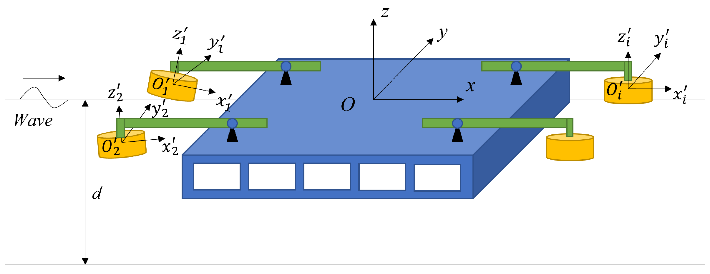
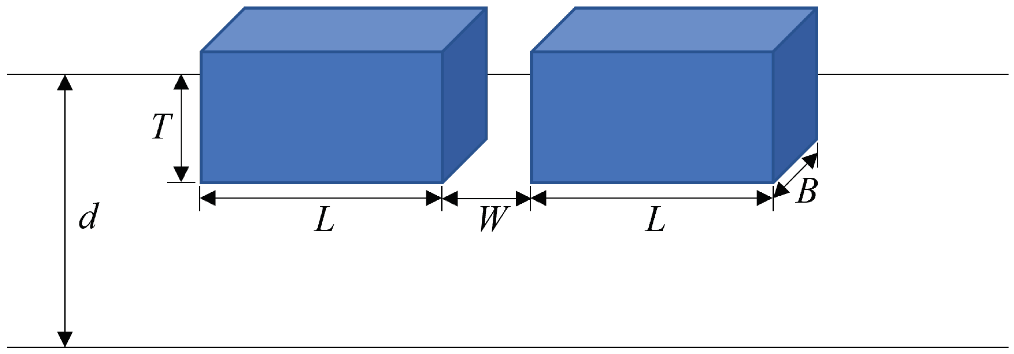
2.1. Calculation of Platform and Floaters

Diffraction theory was adopted for the wave–structure interaction study. A right-hand Cartesian coordinate was established in the computation. One is a space-fixed coordinate system Oxyz with its origin at the still water surface, in which x and y are measured horizontally and z vertically upward. For each floater, a body-fixed coordinate system O i x i y i z i was established to describe the motion of each floater (i denotes the ith floater). The sketch is shown in Figure 1.
Under the assumption of ideal fluid, there exists a velocity potential ϕ that satisfies the Laplace equation and boundary conditions within the fluid domain. The velocity potential and wave elevation can be divided into the incident part and scattered part:
ϕ = ϕ i + ϕ s
η = η i + η s
Thus, the scattered potential satisfies the Laplace equation in the domain as follows:
2 ϕ s = 0
It is subject to the seabed boundary and free surface conditions:
ϕ s z = 0 , z = d
η s t = ϕ s z ϕ s t = g η s , z = 0
For the platform and the floater, the body boundary condition is
ϕ s i n = ϕ i i n + ξ i + α i × x i x 0 i · n i = 0 , 1 , 2 , , N
where the superscript i indicates different floaters, i = 0 denotes the platform, i = 1 , 2 , , N denotes the floater, n denotes the unit normal vector, pointing out of the fluid, and ξ i = ξ 1 i , ξ 2 i , ξ 3 i and α i = α 1 i , α 2 i , α 3 i = ξ 4 i , ξ 5 i , ξ 6 i denote the translation and rotation motion, respectively. x 0 i denotes the rotation center.
To numerically solve the boundary value problem, we employ a Rankine source and its image about the seabed as Green’s function. The second theorem of Green is applied to the scattered potential and Green’s function, and thus, the above boundary value problem is converted to the boundary integral equation.
Once the velocity potential on the body surface is obtained, the wave forces on a body can be computed by integrating the fluid pressure over the mean body surface. The exciting force is expressed as
F i = ρ S b ϕ t n d s i = 0 , 1 , 2 , , N
where ρ denotes the fluid density. Similarly, F 0 indicates the wave exciting force on the platform; F i indicates the wave exciting force on the ith floater.

2.2. Calculation of the Truss Structure

The wave forces on the truss structure are obtained by the Morison formula. The wave force on the unit height is
f s = f i + f d
where f i indicates the inertia force, whose form is the same as the solution of the non-viscous fluid based on wave theory, and f d represents the velocity force, whose form is similar to the resistance on the body surface in steady flow. The formulas for the forces acting on the vertical truss structure are
f i = C m ρ π D 2 4 a
f d = C d ρ 2 D u u
where C m and C d are the coefficients of inertia and velocity force, respectively; D is the cylinder diameter; u and a are the velocity and acceleration of a water particle, respectively.
Due to the effect of the platform and floaters on the wave field, the velocity and acceleration of water are composed of incident and scattered waves, respectively. The parts induced by incident waves can be easily obtained through an analytical expression; however, the parts induced by scattered waves should be solved by wave diffraction theory. The velocity of a water particle produced by diffraction potential can be obtained by the integral equation and is given as
u s , x = ϕ s , x ( x 0 ) t = S 2 G ( x , x 0 ) n x 0 ϕ s ( x ) ϕ s ( x ) n G ( x , x 0 ) x 0 d s
Then, the acceleration of a water particle can be calculated by the time difference:
a s , x = u s , x t = u s , x t u s , x t 1 Δ t
Because the body has reciprocating motion under the wave action, the velocity and acceleration can be calculated by solving the body motion equation, which are defined as u b and a b . Therefore, the relative velocity and acceleration can be written as u r = u u b and a r = a a b , respectively. Therefore, the wave force on a vertical truss structure for a unit of height can be written as follows:
f i = C m ρ π D 2 4 a r
f d = C d ρ 2 D u r u r
The validation of the wave force calculation about the truss structure in the large structure was completed in previous research [25].

2.3. Motion Response
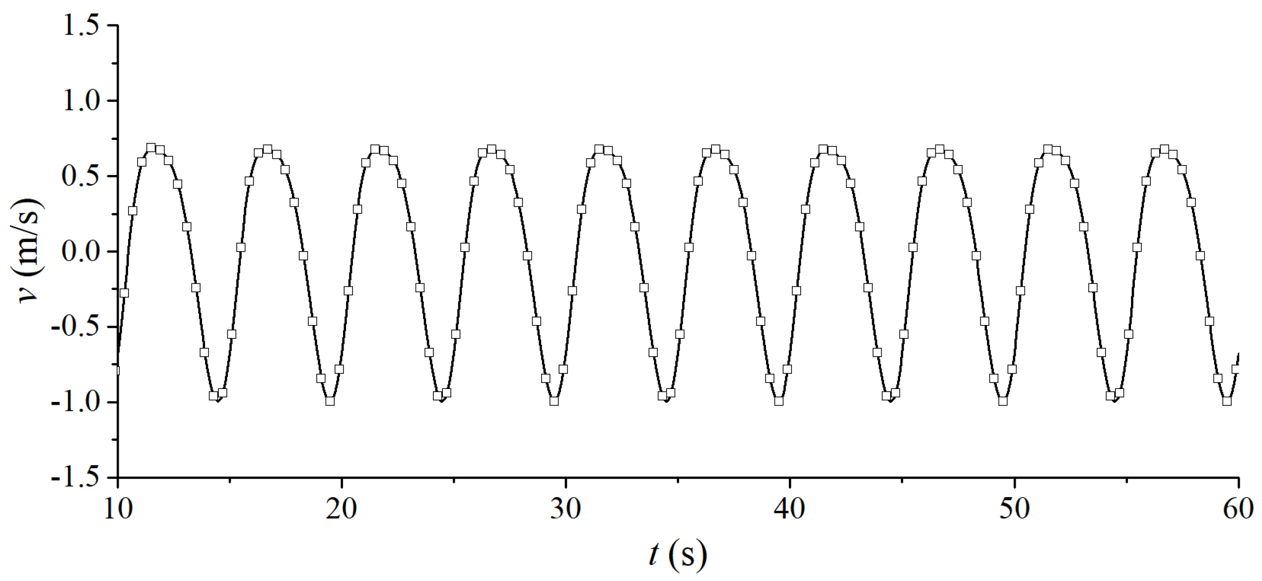
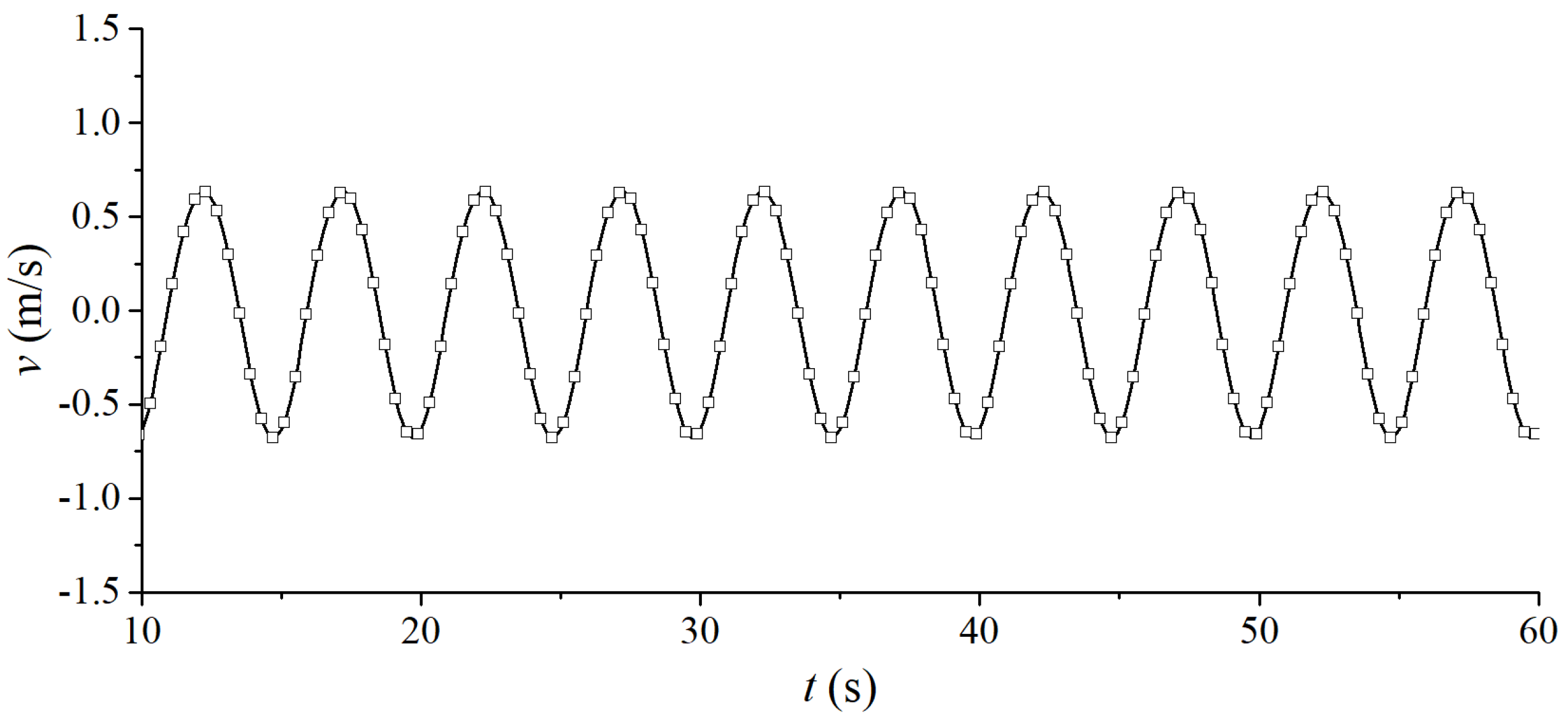
The platform and floater are connected by a floating arm and hydraulic cylinder, as shown in Figure 2.
Based on the lever principle, when the floater is subjected to small wave force, it can push the rear hydraulic cylinder to work and generate power. Therefore, the wave force on the floaters is amplified by the floating arm and acts on the platform, thus affecting the platform movement. The motion equation is required for each floater as follows:
[ M i ] ξ i ¨ + [ B i ] ξ i ˙ + [ C i ] ξ i = F i
where M i , B i and C i are the mass matrix, damping matrix, and stiffness matrix for each floater. For the platform, the motion equation of the platform is expressed by
[ M 0 ] ξ 0 ¨ + [ B 0 ] ξ 0 ˙ + [ C 0 ] ξ 0 = F 0 + i = 1 N L r i L l i F i + F T
where M 0 , B 0 and C 0 are the mass matrix, damping matrix, and stiffness matrix for the platform; L r i and L l i are the floating arm length of the floater side and platform side, respectively, and F T indicates the Morison force on the truss structure.

3. Model Validation

The study of the waves and WEC platform is actually a multi-floating body interaction problem. To validate the numerical model, the linear wave interaction of a twin-box structure is modeled, as shown in Figure 3. L, B, T, and W in Figure 3 represent the length, width, draft, and spacing of the twin-boxes, respectively, and d represents the water depth. The detailed dimensions and calculation parameters of the square box are shown in Table 1. The mass center of the square box is located 2.56 m directly above the center of the box bottom.
This model is applied to calculate the hydrodynamic coefficient and motion response of two free square boxes in regular waves with an incidence angle of 0 degrees. Figure 4 shows the relationship between the wave force and the incident wave frequency of the up-wave box and the back-wave box, respectively. Figure 5 shows the variation of the motion response in the pitch motion of the up-wave box and the back-wave box with the wave frequency.
In the figure, the wave force and motion response are dimensionless. m, g, L, and A are the mass, gravity acceleration, box length, and wave amplitude, respectively. The results show that the calculation results of the present model are consistent with Choi and Hong (2002) [26]. The calculation results are in good agreement only with some differences in individual frequencies. Therefore, this model can be employed in the subsequent hydrodynamic response calculation of the multi-floater truss-type WEC platform.

4. Results and Discussions

The truss-type WEC platform is composed of oscillating floaters and a platform, which are connected by a floating arm and a hydraulic cylinder in the form of a lever. It is described in Figure 1 and Figure 2 above. The parameters of the floater and platform are shown in Table 2 and Table 3. In the platform, there are five large damping boxes in the water to provide buoyancy force. The draft of a damping box is 1.8 m, and the center location is in Table 4.

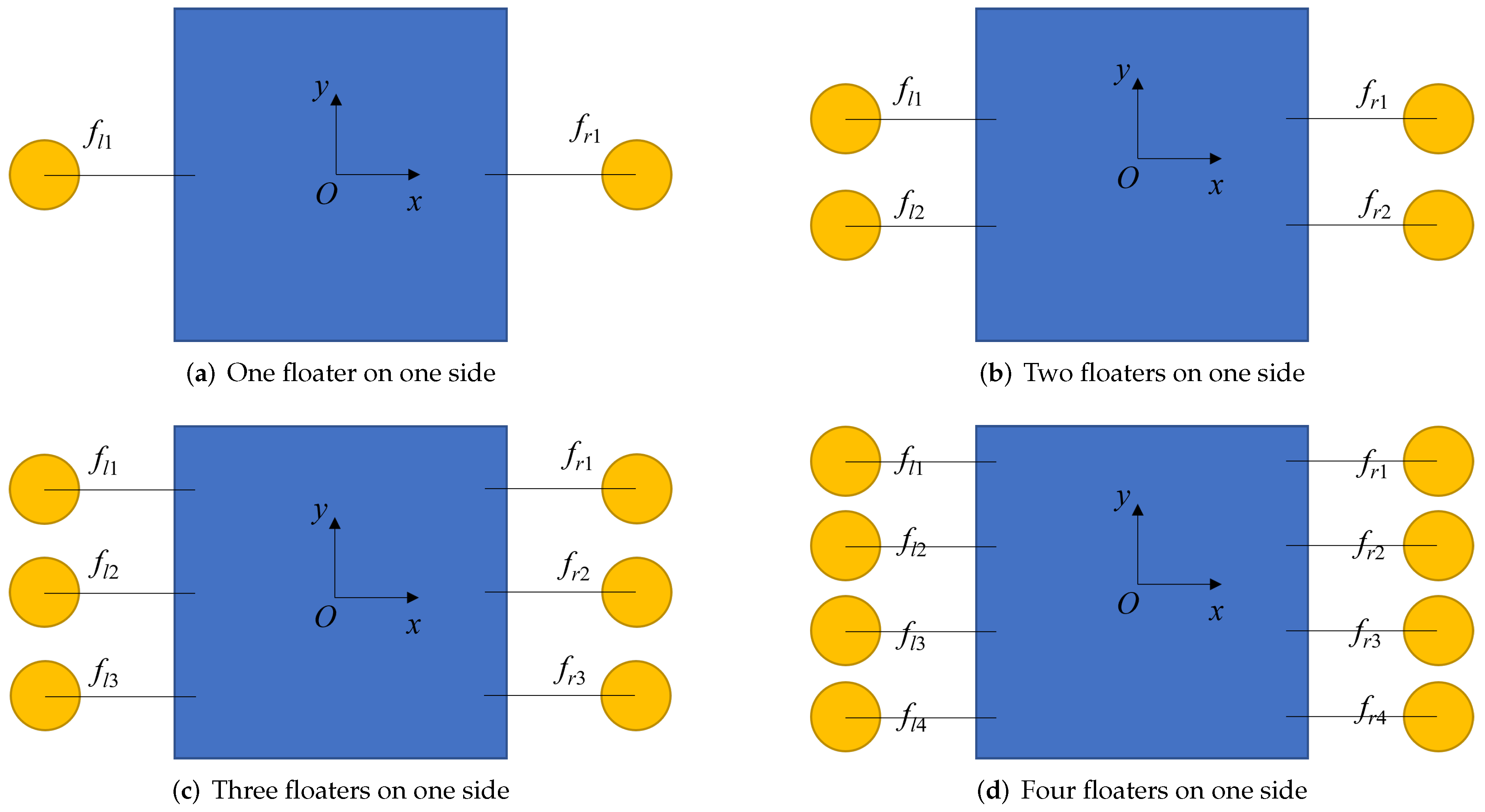
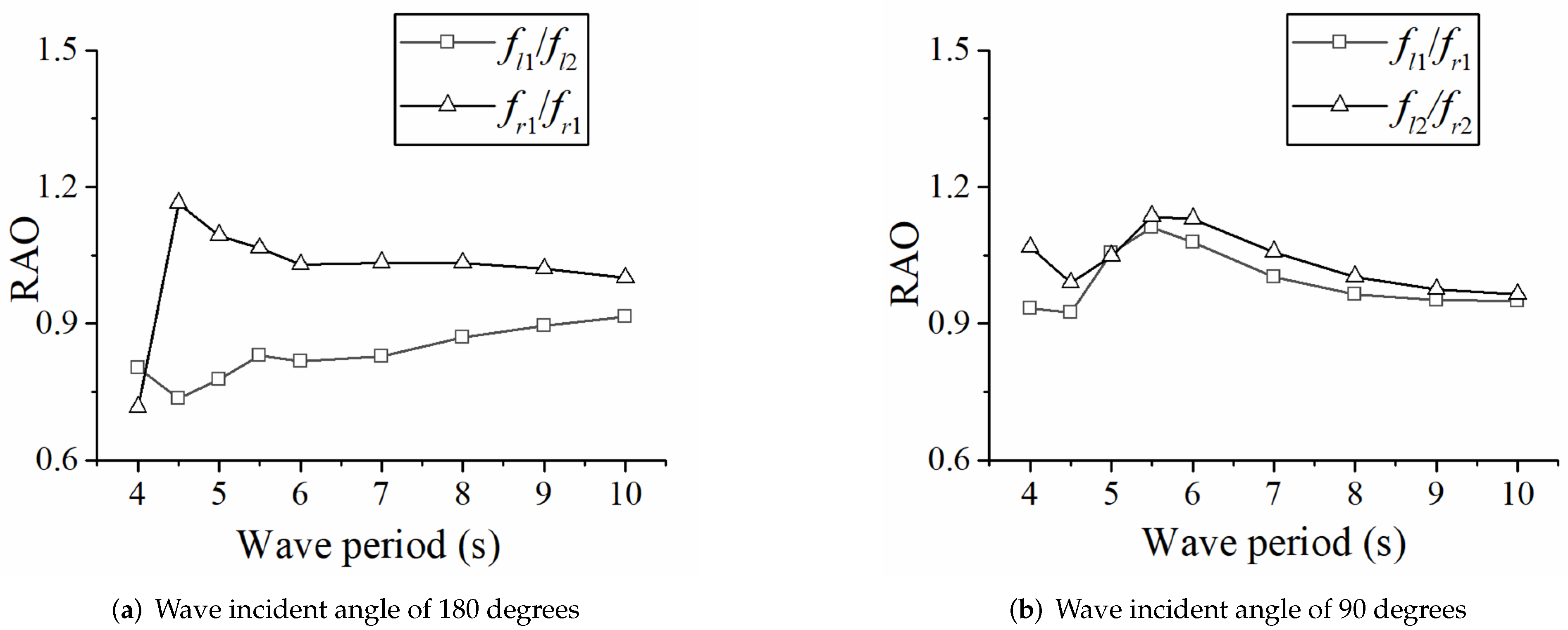
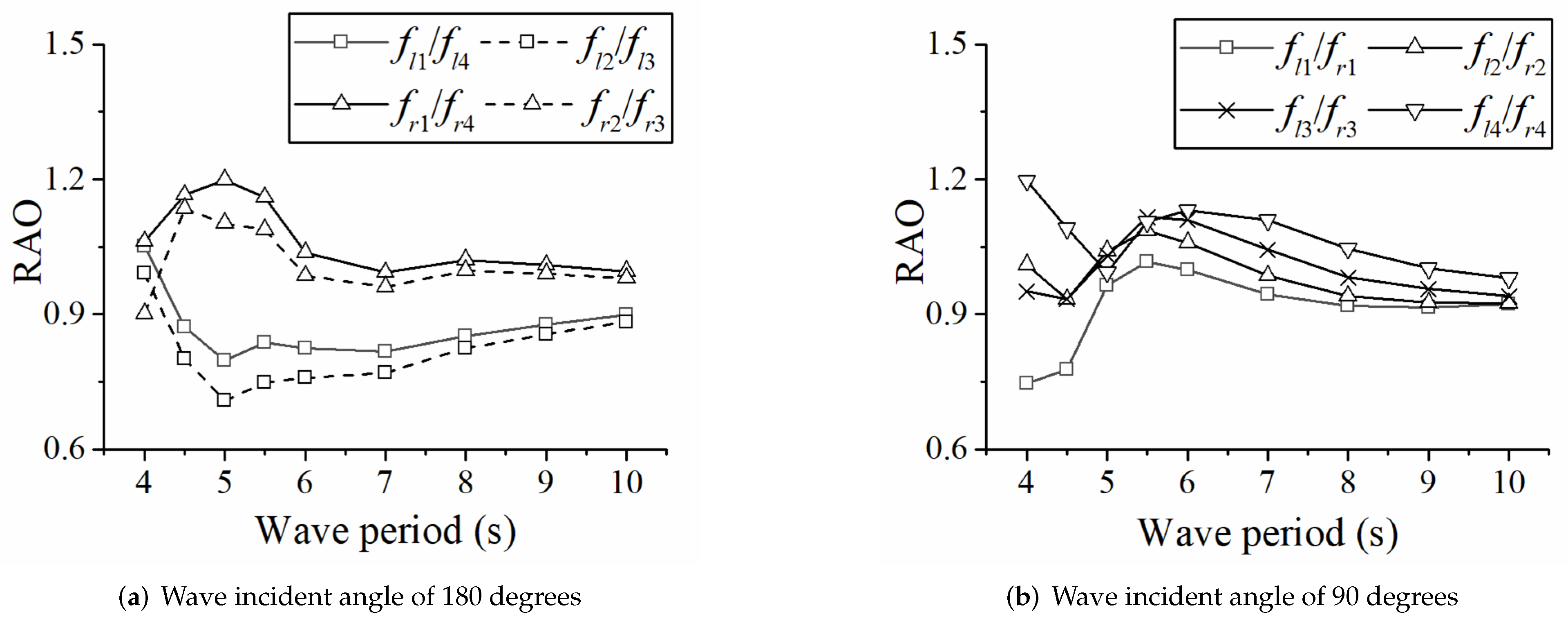
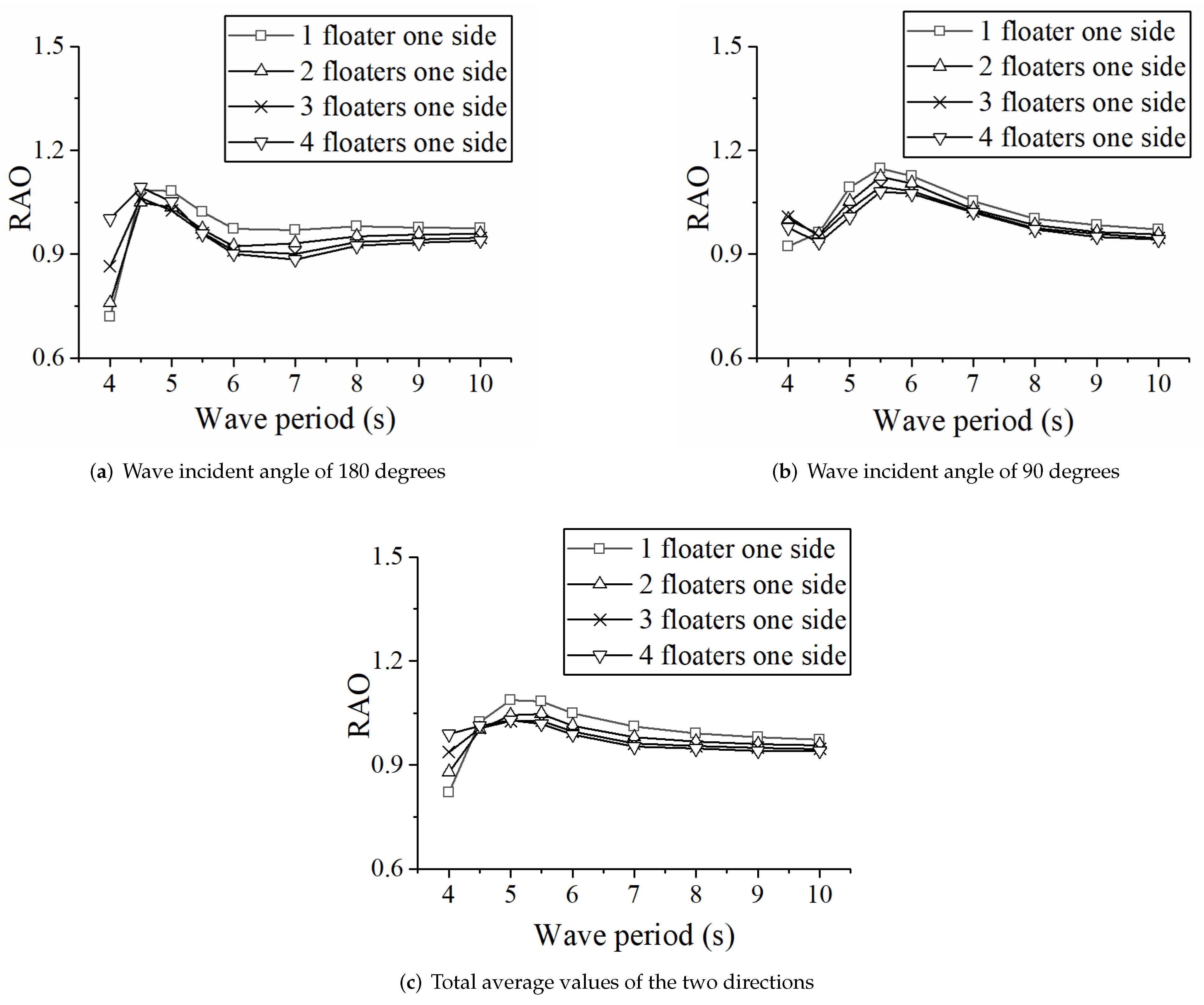
4.1. The Influence of Floater Number on the Motion Response

In order to study the influence of the floater number on the power generation efficiency of the WEC platform, the motion responses of the floaters in the heave motion when the number of single-sided floaters from 1 to 4 are carried out through numerical simulation, and the calculation diagram is shown in Figure 6. The left floaters use f l i ( i = 1 , 2 , 3 , 4 ) to represent the i-th floater on the left side of the platform, and the right floater uses f r i ( i = 1 , 2 , 3 , 4 ) to represent the i-th floater on the right side of the platform. Wave incident angles of 180 degrees and 90 degrees are used here to simulate the wave propagating along the floater arrangement direction and perpendicular to the arrangement direction, respectively.
Firstly, the heave motion responses of the floater are analyzed and compared under regular waves with different periods when a floater is arranged on one side, as shown in Figure 7. The response amplitude operator (RAO) in the y-axis indicates the motion characteristics of the floater in heave motion. The results indicate that when the wave propagates along the direction of the floater arrangement (wave incidence angle of 180 degrees), the motion response of the up-wave floater is greater than that of the back-wave floater, especially in the case of short-period wave action, because the damping boxes of the platform have a certain degree of reflection on the wave. When the wave period is 4 s, the wave force in the heave direction is small, so the heave motion in the period of 4 s is small. The natural period of the single floater is near 5.0 s, so the heave motion in the period of 5 s increases obviously due to the resonance. However, in the case of long-period wave action, the influence of the truss-type platform on the wave propagation becomes smaller, and the motion of the up-wave and back-wave floaters tends to be the same. When the wave propagates perpendicular to the float arrangement direction (the wave incidence angle is 90 degrees), the motion amplitudes of the floaters on both sides are the same.
Then, the results were analyzed when two floaters are arranged on one side, as shown in Figure 8. When the wave propagates along the floater arrangement direction, the heave motion results are similar to those of a single floater. When the wave propagates perpendicular to the floater arrangement direction, the front float has a certain degree of shielding effect on the rear floater, and the motion response is slightly greater than that of the rear floater; however, the overall difference is not large.
Further, the calculation results of three floaters and four floaters on one side were analyzed, as shown in Figure 9 and Figure 10. The conclusion is similar to the previous one. When the wave propagates along the floater arrangement direction, the heave motion of the floaters on both sides is slightly larger than that of the floater in the middle, and the overall motion of the up-wave floater is slightly larger, while the motion of the back-wave floater is slightly smaller. The motion response tends to be consistent with an increase in wave period. When the wave propagates perpendicular to the floater arrangement direction, the motion trends of each float are similar, and the motion response of the front floater is slightly larger than that of the rear floater; however, the overall difference is not significant. Combined with the RAO comparison of different wave periods, when the wave period is small, the damping boxes and floaters influence the wave field, and the motion responses of the up-wave floater are larger than those of the back-wave floater. With an increase in wave period, the relative length of the structure and wavelength becomes small, so the motion trends of the up- and back-wave floaters tend to be consistent.
On the whole, since the platform adopts a truss-type structure; its existence has little effect on the wave field; the difference in the motion response of the floaters under the wave action in all directions is not particularly large; each floater has a good wave-following property. However, the size of the floater is relatively large, and the phenomenon of diffraction and scattering will occur when waves pass through the floater. The heave motion responses of the up-wave floater are larger than those of the back-wave floaters.

4.2. The Selection of Floater Arrangement

Based on the above four situations, the optimal floater arrangement is selected by considering the power generation efficiency and economy of the device as a whole. Under the conditions of 0° and 90° incident waves, the average RAOs of the floater are shown in Figure 11. The total average RAOs of the two directions are shown in Figure 11c. Whether the wave propagates along the floater arrangement direction or the wave propagates perpendicular to the floater arrangement direction, the RAOs of the floater are the largest in the case of a single floater arrangement in most cases, and with an increase in the number of arranged floaters, the average RAOs of the floater become smaller. When the wave period is 5 s, the heave motion responses of the floaters reach a maximum. This shows that within a certain range, although the existence of the floater has an influence on the motion response, the overall quality of the floater is small and the size of the float is not particularly large, so the effect is limited. The floaters as a whole show a very good wave-following property. Therefore, arranging as many floaters as possible can effectively improve the power efficiency of the WEC platform.

5. Calculation of Energy Utilization Efficiency of WEC Platform

5.1. Theory of Capture Efficiency

Wave potential energy and kinetic energy together make up the total wave energy stored per unit area in the length of a single wide wave crest line per unit wavelength. In Airy wave theory, it can be expressed as
E p = E k = 1 16 ρ g H 2 λ
where E p denotes wave potential energy, E k denotes wave kinetic energy, H denotes the wave height, and λ denotes wavelength. The average total wave energy of the peak line length of a single width within the unit wavelength is
E = E p + E k λ = 1 8 ρ g H 2
Therefore, the average total energy of waves in the rectangular area corresponding to the floater within a wave period is
E f = E · A t = 1 8 ρ g H 2 A t
where A t denotes the rectangular area corresponding to the floater, which is the width of the float multiplied by the wavelength. The energy captured by the floater from the ocean waves is mainly transformed into two parts, namely the kinetic energy and potential energy of the floater. The kinetic energy absorbed by the floater can be expressed as:
E f k ( t ) = 1 2 ( m + m a ) v 2 = 1 2 ( m + m a ) ω 2 A 2 sin 2 ( ω t + φ )
The potential energy absorbed by the floater can be expressed as:
E f p t = 1 2 k x 2 = 1 2 ρ g A w x 2 = 1 2 ρ g A w A 2 cos 2 ω t + φ
Therefore, the total wave energy absorbed by the floater system can be expressed as:
E f z t = E f k t + E f p t = 1 2 ( m + m a ) ω 2 A 2 sin 2 ( ω t + φ ) + 1 2 ρ g A w A 2 cos 2 ω t + φ
where m denotes the floater mass, m a denotes the added mass of the floater, and A w denotes the water line area of the floater. The wave energy captured by the oscillating floater system within a wave period is:
E f 2 = 0 W T E f z t d t
Therefore, the energy capture efficiency of the WEC platform can be expressed as the ratio of the total energy absorbed by the floater to the total energy of the wave in the width area of the floater, that is:
η f = E f 2 E f

5.2. Capture Efficiency of WEC Platform

In the multi-floater WEC platform system, the heave motion of the floater relative to the platform overcomes the damping force to produce useful power, and the power take-off (PTO) system converts the mechanical energy of floater movement into electrical energy. In fact, in order to simplify the model, we use the linear damping model to analyze the damping force of the PTO system. In addition, there are some studies that have used the same linear damping model to consider the PTO system [27,28]. We simulate the damping force in the PTO system, fd, using the following equation
f d = C d , f · v
where v is the heaving velocity of the floater and C d , f is a linear damping coefficient, which represents the performance of the PTO system. The absorbed power is represented by
P = 1 W T 0 W T f d · v d t = 1 W T 0 W T C d , f · v 2 d t
where f d is the damping force and W T is the wave period. The different damping coefficients C d , f were selected by testing several damping coefficients, before the best value, which yields the maximum absorption power, was eventually determined.
In this WEC platform, the floater is connected to the platform through the floating arm, which makes the floater have a heave movement in the wave field. The end of the floating arm pushes the PTO power output device through the lever principle to overcome the PTO damping. The work in this part is the energy used by the power generation system of the device. In the process of capturing wave energy by the power generation system, the influence of PTO damping on energy capture efficiency is very significant. The value of PTO damping can change the heave motion response and motion velocity of the floater, thus affecting the capture of wave energy by the floater. Therefore, it is particularly necessary to study the impact of different linear PTO damping on the capture efficiency of the device. In the numerical simulation, a constant “C” is introduced as the damping coefficient to adjust the damping force. Through the simulation of the multi-floater WEC platform with different linear damping coefficients C, the influence of different linear PTO damping coefficients on capture efficiency is explored. The linear damping coefficient C is introduced in the equation and the total absorbed power of the floater in the case of damping coefficient C.
In the numerical simulation, the linear damping coefficient in the heave direction is added to one floater. The wave propagates along the floater arrangement direction, and the wave amplitude is 0.5 m; the wave period is 5 s when the floater average RAO is the maximum. The velocities of the floater in the heave motion with time are calculated here. The velocity time histories under some different linear damping coefficients C are shown in Figure 12, Figure 13, Figure 14 and Figure 15. The results show that the velocity of the floater decreases significantly with an increase in the linear damping coefficient.
Furthermore, the power of the floater to capture wave energy under different linear PTO damping coefficients can be calculated, as shown in Figure 16a. Therefore, the relationship between the energy capture efficiency of the floater and the linear PTO damping coefficient C is calculated as shown in Figure 16b. With an increase in the linear damping coefficient C, the capture efficiency of the floater first increases, then decreases, and reaches the maximum when C = 30,000 N/(m/s); thus, it is concluded that C = 30,000 N/(m/s) is the optimum PTO damping coefficient for the WEC platform. The wave capture efficiency of each floater of the WEC platform is further obtained, as shown in Table 5.

6. Conclusions

Based on potential flow theory, the mathematical model of the interaction between wave and WEC platform was established by using the high-order boundary element method. The motion response of each floater of the multi-floater truss-type WEC platform was studied. The influence of the number of floaters and the arrangement of floaters on the motion of the floater was analyzed. The effect of the hydraulic cylinder on the float was simulated by linear damping to generate power. The multi-float truss-type WEC generation device was simulated, and the following conclusions were obtained:
  • Since the platform is composed of a truss structure, the floaters’ motion responses under wave action in all directions are very close, and each floater has good wave-following performance. The motion response of the up-wave floater is slightly greater than that of the back-wave floater, and the motion response of the side floaters is slightly greater than that of the middle floater.
  • With an increase in the number of floaters arranged at one side, the average RAO of the floats is smaller, but the overall difference is small. Multiple floaters as a whole show very good wave-following performance. Therefore, if conditions permit, arranging as many floats as possible can effectively improve the power generation efficiency of the platform.
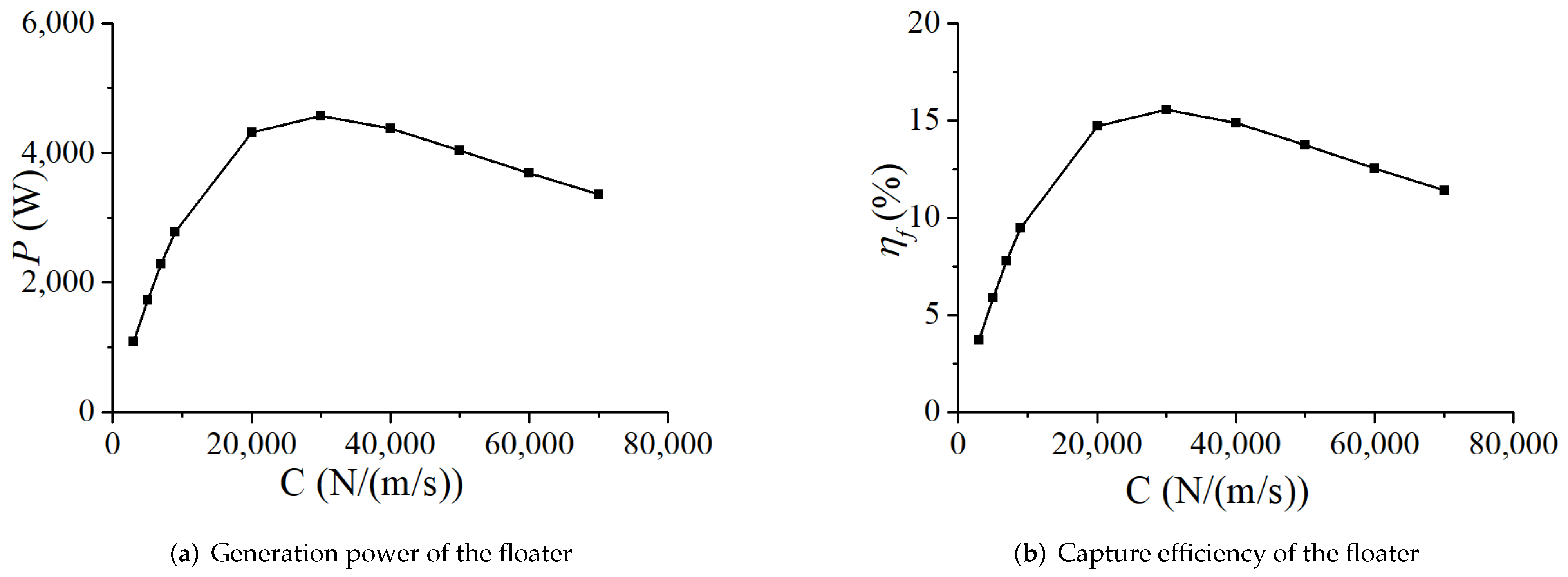
  • The power and efficiency of a single float first increase and then decrease with the increase of linear damping under the regular wave action. When the damping is 30,000 N/(m/s), the power generation efficiency is the highest, and the capture efficiency of the whole platform is 9.7%

Author Contributions

Conceptualization, R.J. and J.W.; methodology, R.J.; software, J.W.; validation, J.W.; writing—original draft preparation, R.J.; writing—review and editing, B.G. and Z.L.; funding acquisition, H.C. All authors have read and agreed to the published version of the manuscript.

Funding

This work was supported by the Application Demonstration of High-Reliability Marine Energy Supply Equipment (GHME2018SF02); Basic Funding of the Central Public Research Institutes (TKS20200406, TKS20210108); Science and Technology Research and Development Project of CSCES (CSCEC-2020-Z-21).

Institutional Review Board Statement

Not applicable.

Informed Consent Statement

Informed consent was obtained from all subjects involved in the study.

Conflicts of Interest

The authors declare no conflict of interest.

References

  1. Zhang, D.H.; Li, W.; Lin, Y.G. Wave energy in China: Current status and perspectives. Renew. Energy 2009, 34, 2089–2092. [Google Scholar] [CrossRef]
  2. Nielsen, K.; Smed, P.F. Point absorber-optimization and survival testing. In Proceedings of the Third European Wave Energy Conference, Patras, Greece, 30 September–2 October 1998; Volume 18. [Google Scholar]
  3. Prado, M. Archimedes wave swing (AWS). In Ocean Wave Energy; Springer: Berlin, Germany, 2008; pp. 297–304. [Google Scholar]
  4. Cleason, L.; Forsberg, J.; Ryler, A.; Sjöström, B.O. Contribution to the theory and experience of energy production and transmission from the buoy-concept. In Proceedings of the 2nd International Symposium on Wave Energy Utilization, Trondheim, Norway, 22–24 June 1982; pp. 345–370. [Google Scholar]
  5. Chang-Lei, M.A.; Xia, D.W.; Wang, M. Review on the Progress of Marine Renewable Energy Technologies in the World. J. Ocean Technol. 2017, 36, 70–75. (In Chinese) [Google Scholar]
  6. Korde, U.A. On controlled oscillating bodies with submerged reaction mass. In Proceedings of the OMAE 2003 22nd International Conference on Offshore Mechanics and Arctic Engineering, Cancun, Mexico, 8–13 June 2003. [Google Scholar]
  7. Caska, A.J.; Finnigan, T.D. Hydrodynamic characteristics of a cylindrical bottom-pivoted wave energy absorber. Ocean Eng. 2008, 35, 6–16. [Google Scholar] [CrossRef]
  8. Zhao, X.L.; Ning, D.Z.; Zhang, C.W.; Kang, H.G. Hydrodynamic Investigation of an Oscillating Buoy Wave Energy Converter Integrated into a Pile-Restrained Floating Breakwater. Energies 2017, 10, 712. [Google Scholar] [CrossRef] [Green Version]
  9. Cao, C. Investigation on Hydrodynamic Performance of Wave Energy Float Pendulum System. Master’s Thesis, Suzhou University, Suzhou, China, 2019. (In Chinese). [Google Scholar]
  10. Zhou, Z. Mooring Hydrodynamics Analysis of Oscillating Float Wave Power Generator. Master’s Thesis, Ningbo University, Ningbo, China, 2019. (In Chinese). [Google Scholar]
  11. Zhou, B.H. The Research of Pitching Float Type Wave Energy Conversion Device. Master’s Thesis, Harbin Engineering University, Harbin, China, 2018. [Google Scholar]
  12. Zhang, H.M.; Zhou, B.Z.; Vogel, C.; Willden, R.; Zang, J.; Geng, J. Hydrodynamic performance of a dual-floater hybrid system combining a floating breakwater and an oscillating-buoy type wave energy converter. Appl. Energy 2020, 259, 114212. [Google Scholar] [CrossRef]
  13. Finnegan, W.; Rosa-Santos, P.; Taveira-Pinto, F.; Geooins, J. Development of a numerical model of the CECO wave converter using computational fluid dynamics. Ocean Eng. 2021, 219, 108416. [Google Scholar] [CrossRef]
  14. Luan, Z.X.; He, G.H.; Zhang, Z.G.; Jing, P.L.; Jin, R.J.; Geng, B.L.; Liu, C.G. Study on the optimal wave energy absorption power of a float in waves. J. Mar. Sci. Eng. 2019, 7, 269. [Google Scholar] [CrossRef] [Green Version]
  15. Liu, Q.L. Study on the Wave Energy Conversion Characteristics of an Array of Floating Point Absorbers. Ph.D. Thesis, Tsinghua University, Beijing, China, 2016. (In Chinese). [Google Scholar]
  16. Yang, S.H.; He, G.Y.; He, H.Z. Response and Efficiency Analysis of Oscillating Float Array Based on Hydrodynamic Simulation. In Proceedings of the State Oceanic Administration of the State Oceanic Technology Center Proceedings of the 4th China Marine renewable Energy Development Annual Conference and Forum, Suzhou, China, 21–23 October 2015; pp. 58–64. (In Chinese). [Google Scholar]
  17. Chrasekaran, S.; Sricharan, V.V.S. Numerical study of bean-float wave energy converter with float number parametrization using WEC-Sim in regular waves with the Levelized Cost of Electricity assessment for Indian sea states. Ocean Eng. 2021, 237, 109591. [Google Scholar] [CrossRef]
  18. Marchesi, E.; Negri, M.; Malavasi, S. Development and analysis of a numerical model for a two-oscillating-body wave energy converter in shallow water. Ocean Eng. 2020, 214, 107765. [Google Scholar] [CrossRef]
  19. He, G.H.; Luan, Z.X.; Jin, R.J.; Zhang, W.; Wang, W.; Zhang, Z.G.; Jing, P.L.; Liu, P.F. Numerical and experimental study on absorber-type wave energy converters concentrically arranged on an octagonal platform. Renew. Energy 2022, 188, 504–523. [Google Scholar] [CrossRef]
  20. Negri, M.; Malavasi, S. Wave Energy Harnessing in Shallow Water through Oscillating Bodies. Energies 2018, 11, 2730. [Google Scholar] [CrossRef] [Green Version]
  21. Ramadanad, A.; Mohamedbc, M.H.; Gabbard, H.A. Experimental analysis of an enhanced design of float with inverted cup for wave energy conversion. Ocean Eng. 2022, 249, 110910. [Google Scholar] [CrossRef]
  22. Moreno, E.C.; Stansby, P.K. The 6-float wave energy converter M4: Ocean basin tests giving capture width, response and energy yield for several sites. Renew. Sustain. Energy Rev. 2019, 104, 307–318. [Google Scholar] [CrossRef] [Green Version]
  23. Stansby, P.K.; Moreno, E.C. Hydrodynamics of the multi-float wave energy converter M4 with slack moorings: Time domain linear diffraction-radiation modeling with mean force and experimental comparison. Appl. Ocean Res. 2020, 97, 102070. [Google Scholar] [CrossRef]
  24. Santo, H.; Taylor, P.H.; Stansby, P.K. The performance of the three-float M4 wave energy converter off Albany, on the south coast of western Australia, compared to Orkney (EMEC) in the U.K. Renew. Energy 2020, 146, 444–459. [Google Scholar] [CrossRef]
  25. Jin, R.J.; Gou, Y. Motion response analysis of large-scale structures with small-scale cylinders under wave action. Ocean. Eng. 2018, 115, 65–74. [Google Scholar] [CrossRef]
  26. Choi, Y.; Hong, S. An Analysis of Hydrodynamic Interaction of Floating Multi-Body Using Higher-Order Boundary Element Method. In Proceedings of the International Offshore and Polar Engineering Conference, Kitakyushu, Japan, 26–31 May 2002; Volume 12, pp. 303–308. [Google Scholar]
  27. Chrasekaran, S.; Sricharan, V.V.S. Numerical analysis of a new multi-body floating wave energy converter with a linear power take-off system. Renew. Energy 2020, 159, 250271. [Google Scholar]
  28. Kim, K.H.; Park, S.; Kim, J.R.; Cho, I.H.; Hong, K. Numerical and experimental analyses on motion responses on heaving point Absorbers connected to large semi-submersibles. Processes 2021, 9, 1363. [Google Scholar] [CrossRef]
Figure 1. Sketch of the wave and multi-floater truss-type WEC platform.
Energies 15 05675 g001
Figure 2. Sketch of the connection relationship of the platform, hydraulic cylinder, and floater.
Energies 15 05675 g002
Figure 3. Sketch of the wave interaction a twin-box structure.
Energies 15 05675 g003
Figure 4. Wave forces of barges in the surge direction: (a) up-wave barge; (b) back-wave barge [26].
Energies 15 05675 g004
Figure 5. Displacement of barges in the surge direction: (a) up-wave barge; (b) back-wave barge [26].
Energies 15 05675 g005
Figure 6. Sketch of floaters’ arrangement for different cases.
Energies 15 05675 g006
Figure 7. Heave motion response of floaters in different wave periods (one floater on one side).
Energies 15 05675 g007
Figure 8. Heave motion response of floaters in different wave periods (two floaters on one side).
Energies 15 05675 g008
Figure 9. Heave motion response of floaters in different wave periods (three floaters on one side).
Energies 15 05675 g009
Figure 10. Heave motion response of floaters in different wave periods (four floaters on one side).
Energies 15 05675 g010
Figure 11. Average heave motion response of floaters in different wave periods.
Energies 15 05675 g011
Figure 12. Velocity time histories of the floater when linear damping coefficient C is 3000 N/(m/s).
Energies 15 05675 g012
Figure 13. Velocity time histories of the floater when linear damping coefficient C is 20,000 N/(m/s).
Energies 15 05675 g013
Figure 14. Velocity time histories of the floater when linear damping coefficient C is 30,000 N/(m/s).
Energies 15 05675 g014
Figure 15. Velocity time histories of the floater when linear damping coefficient C is 70,000 N/(m/s).
Energies 15 05675 g015
Figure 16. Generation power and capture efficiency of the floater to capture wave energy under different linear PTO damping coefficients.
Energies 15 05675 g016
Table 1. Parameters of the double-box model.
SymbolMeaningValue
LLength (m)30
BWidth (m)22
TDraft (m)1.5
dWater depth (m)15
WDistance of twin-boxes (m)8
R x Rotation radius around x-axis (m)9.0
R y Rotation radius around y-axis (m)6.6
R z Rotation radius around z-axis (m)10.8
Table 2. Parameters of the platform.
MeaningValue
Size of platform20 m
Mass of platform 1.025 × 10 5 kg
Mass center of platform(0.0, 0.0, 0.0)
Rotation center of platform(0.0, 0.0, 0.0)
Platform moment of inertia I x x 6.56 × 10 6 kg·m 2
Platform moment of inertia I y y 6.56 × 10 6 kg·m 2
Platform moment of inertia I z z 9.72 × 10 6 kg·m 2
Distance between floater and platform edge5 m
Distance between adjacent floater edge1 m
Truss diameter 0.06 m
Truss number in one side6
Table 3. Parameters of one floater.
MeaningValue
Diameter of floater3 m
Mass of floater3000 kg
Draft of floater1 m
Mass of floating arm300 kg
Length of floating arm7 m
Displacement7.07 m 3
Floater moment of inertia I x x 2687 kg·m 2
Floater moment of inertia I y y 2687 kg·m 2
Floater moment of inertia I z z 3375 kg·m 2
Table 4. Location of damping boxes (unit: m).
Damping Box 1Damping Box 2Damping Box 3Damping Box 4Damping Box 5
(8.35, 8.35)(8.35, −8.35)(−8.35, −8.35)(−8.35, 8.35)(0.0, 0.0)
Table 5. Capture efficiency of each floater.
Floater number f l 1 f l 2 f l 3 f l 4
η f % 5.384.074.075.38
Floater number f r 1 f r 2 f r 3 f r 4
η f % 15.5513.8013.8015.55
Publisher’s Note: MDPI stays neutral with regard to jurisdictional claims in published maps and institutional affiliations.

