
A Novel Control Strategy in Grid-Integrated Photovoltaic System for Power Quality Enhancement


Abstract
:1. Introduction
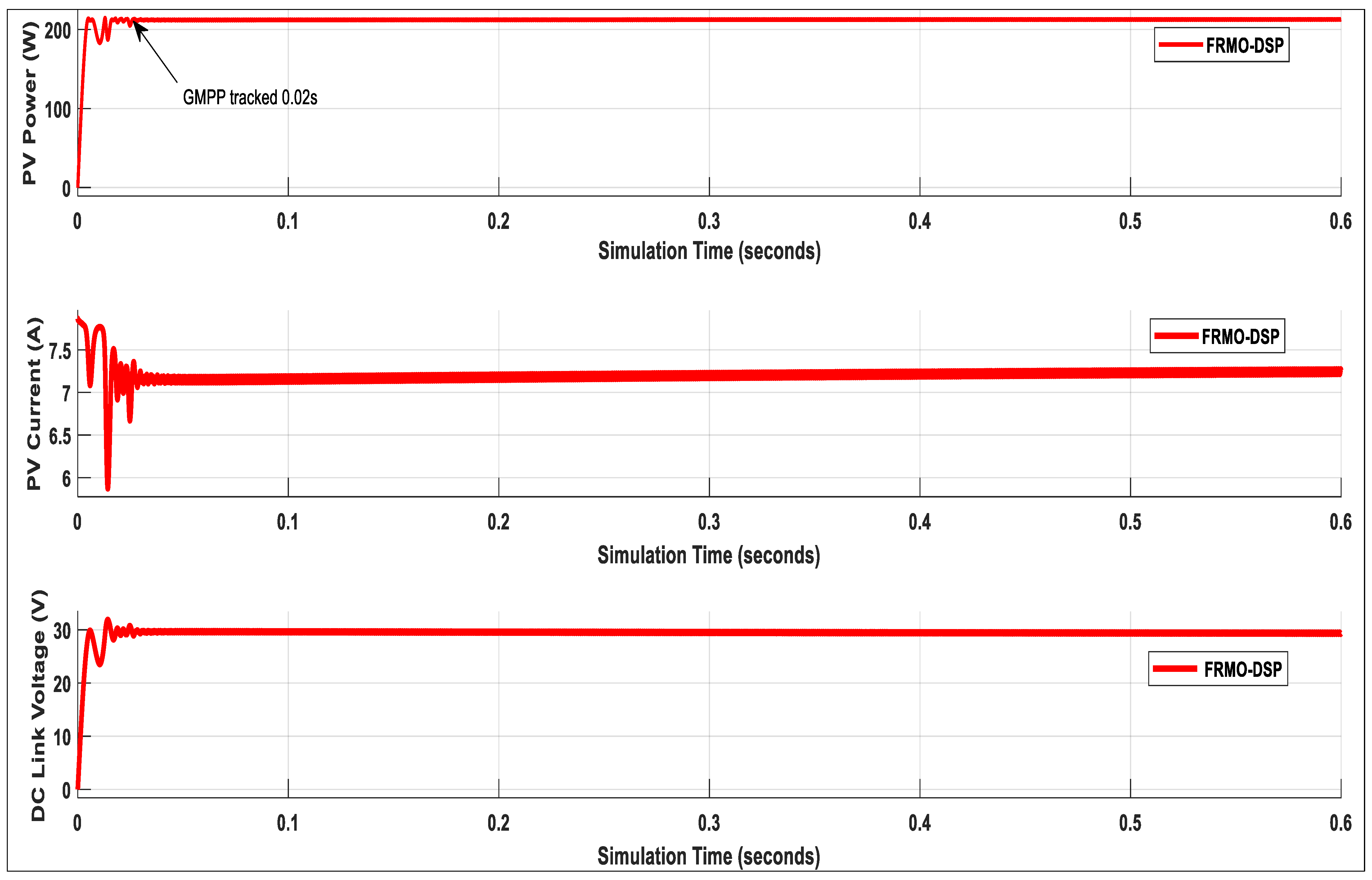
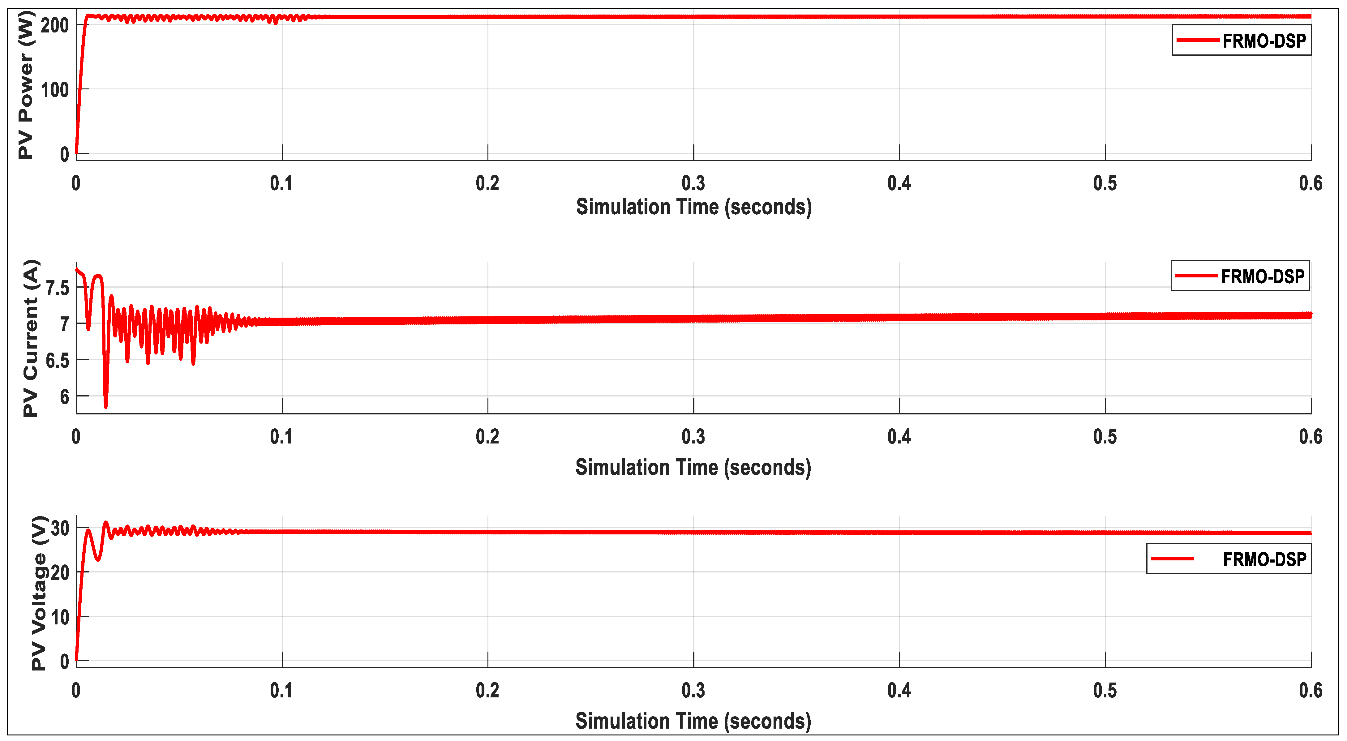
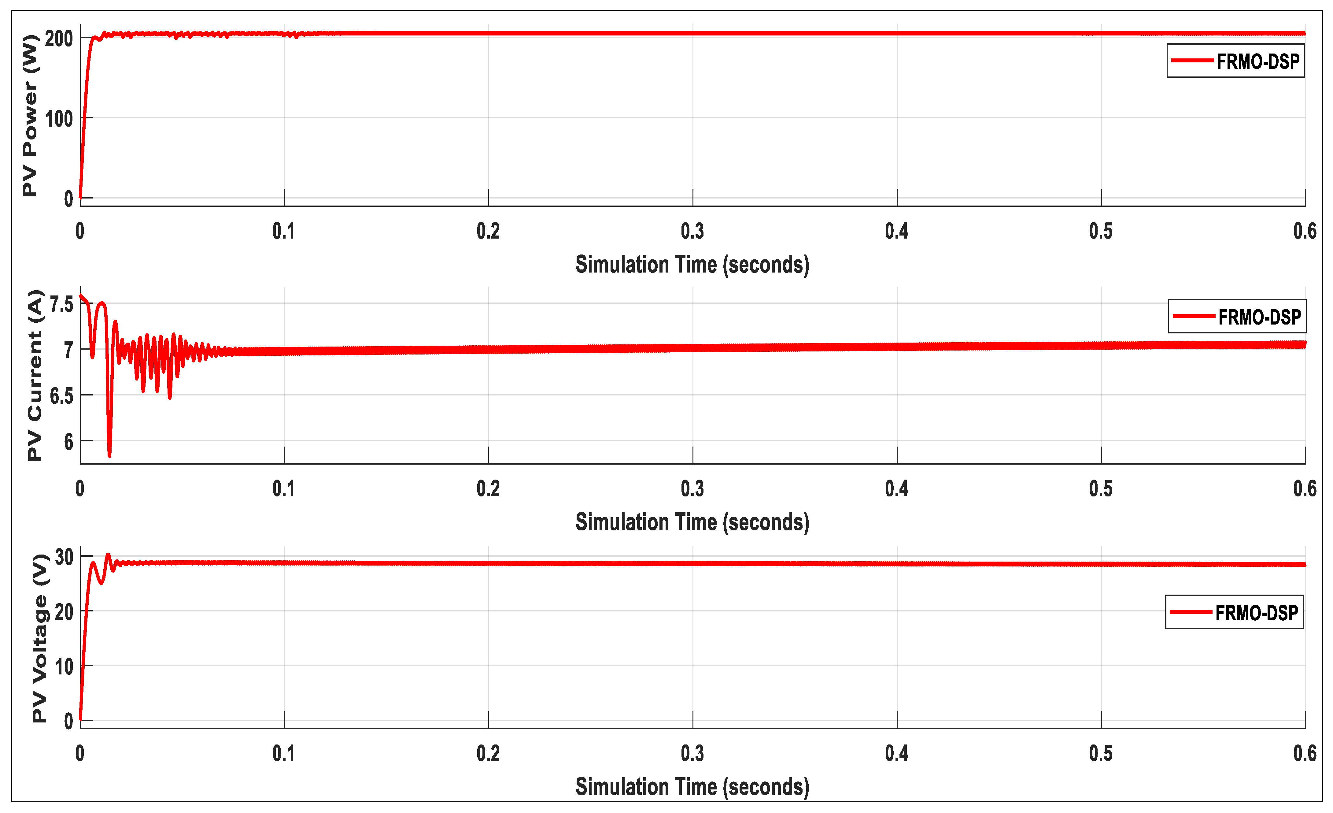
- A new FRMO based on the DSP MPPT technique is proposed to track the PV system’s global maximum power under fast-changing weather conditions using a fixed-tilt installation configuration.
- The proposed FRMO-DSP MPPT is integrated with the PID controller to minimize the steady-state error and maintain the optimal voltage level at the DC link bus.
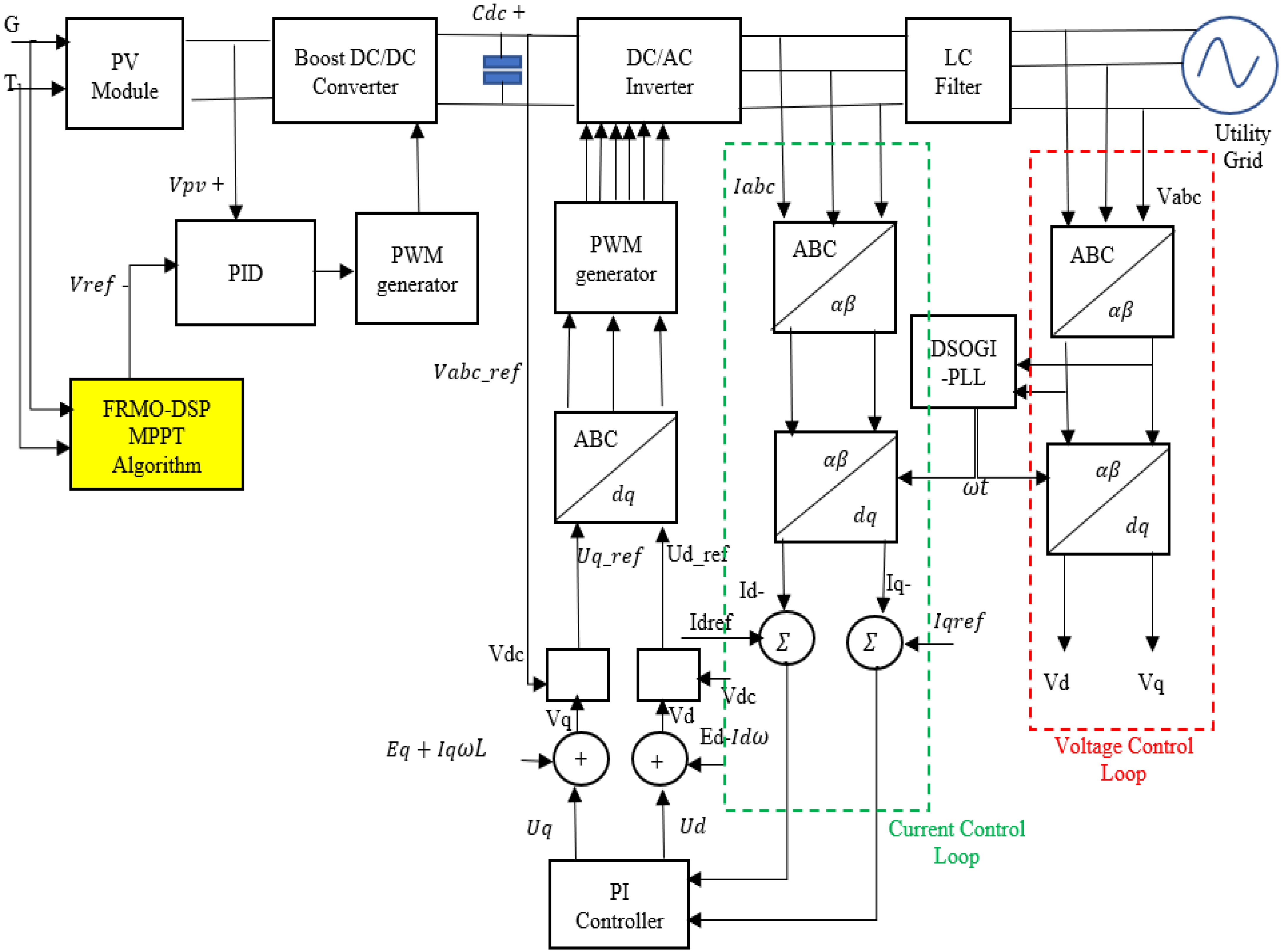
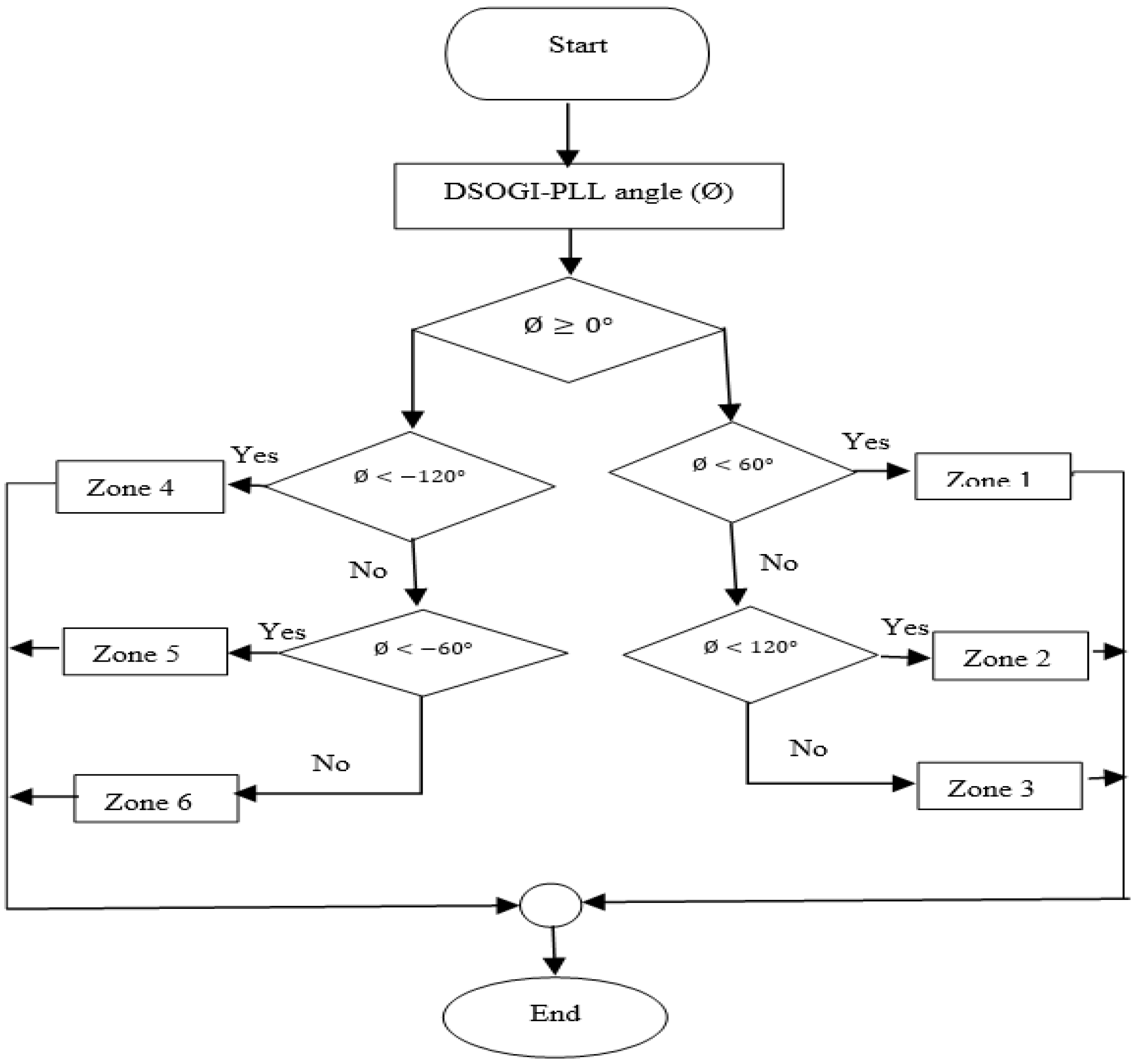
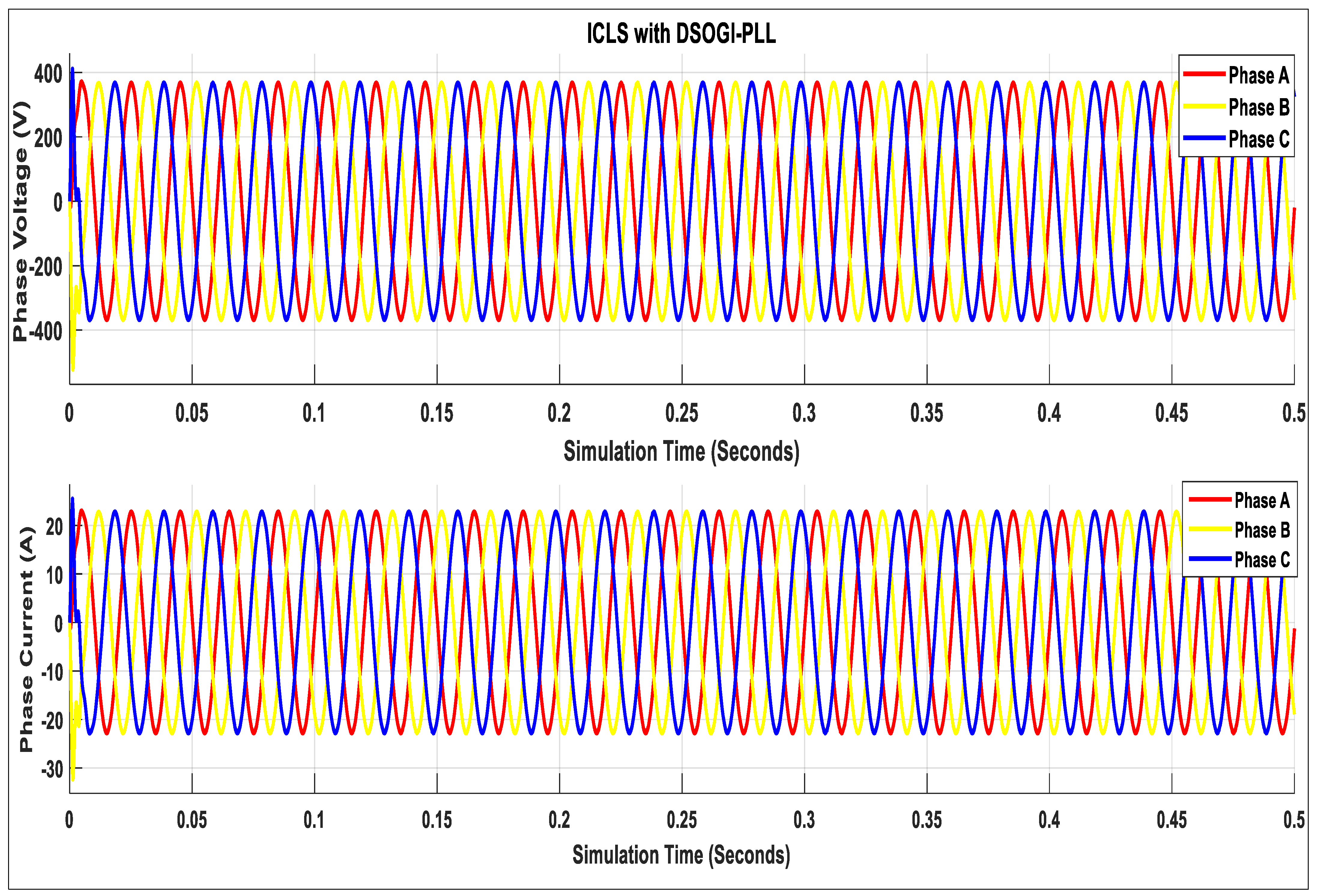
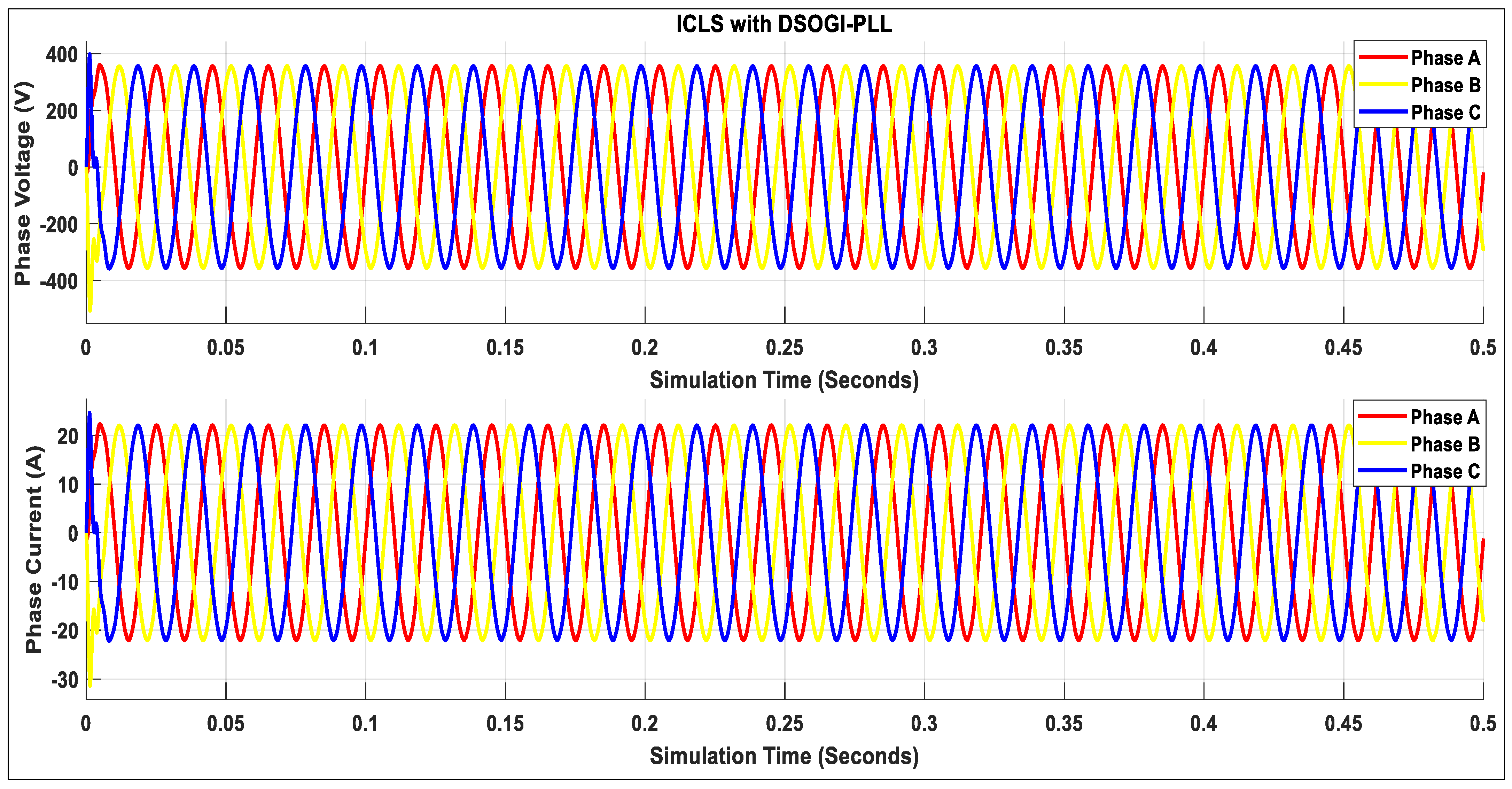
- A novel inverter control loop system with a DSOGI-PLL is proposed to calculate the three-phase reference voltage to generate the optimum PWM signals for the grid interfacing inverter to enhance the power quality of the grid-integrated PV system.
- The proposed system ensures rapid grid synchronization and convergence time to meet the benchmark of the grid requirements.
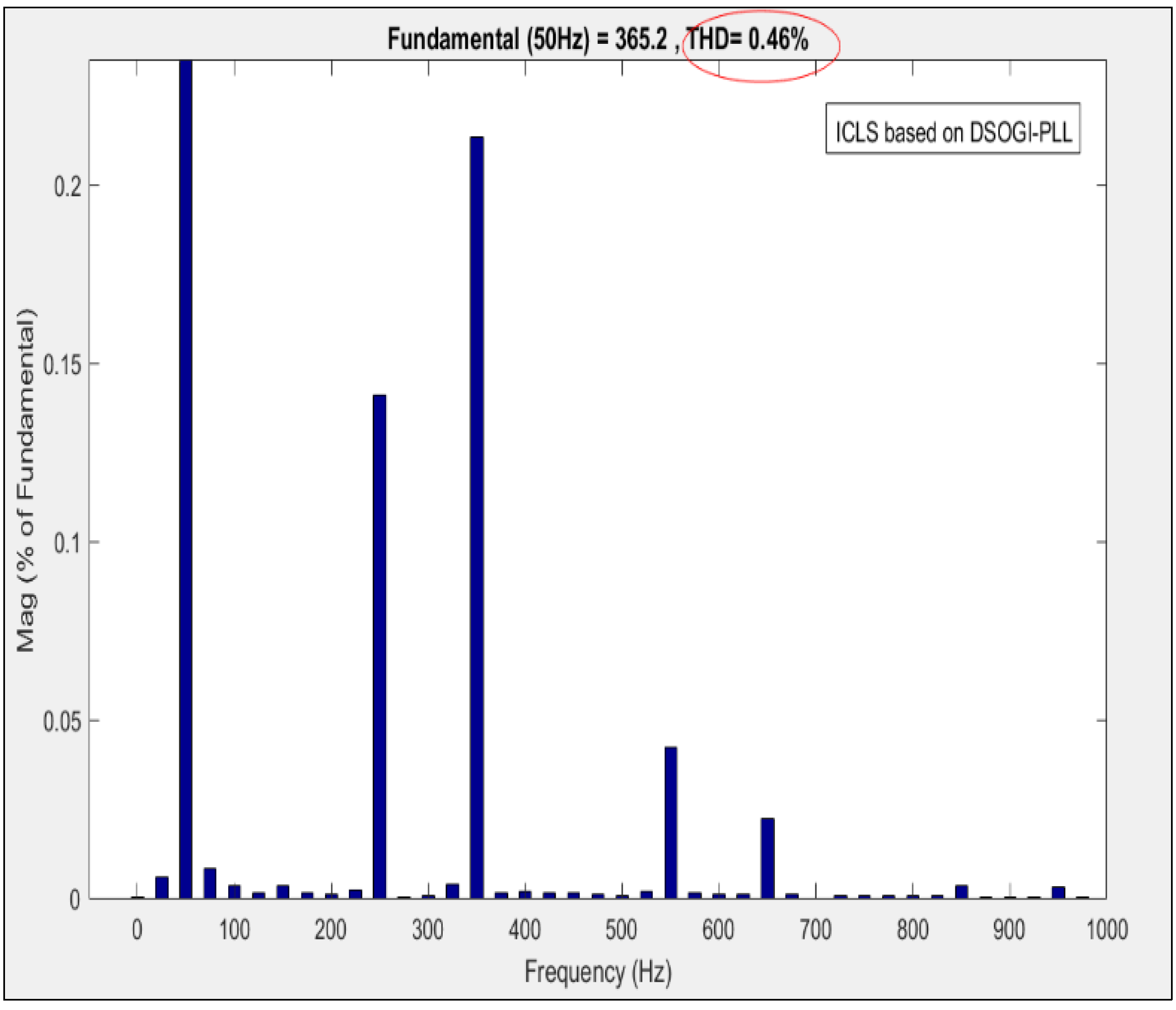
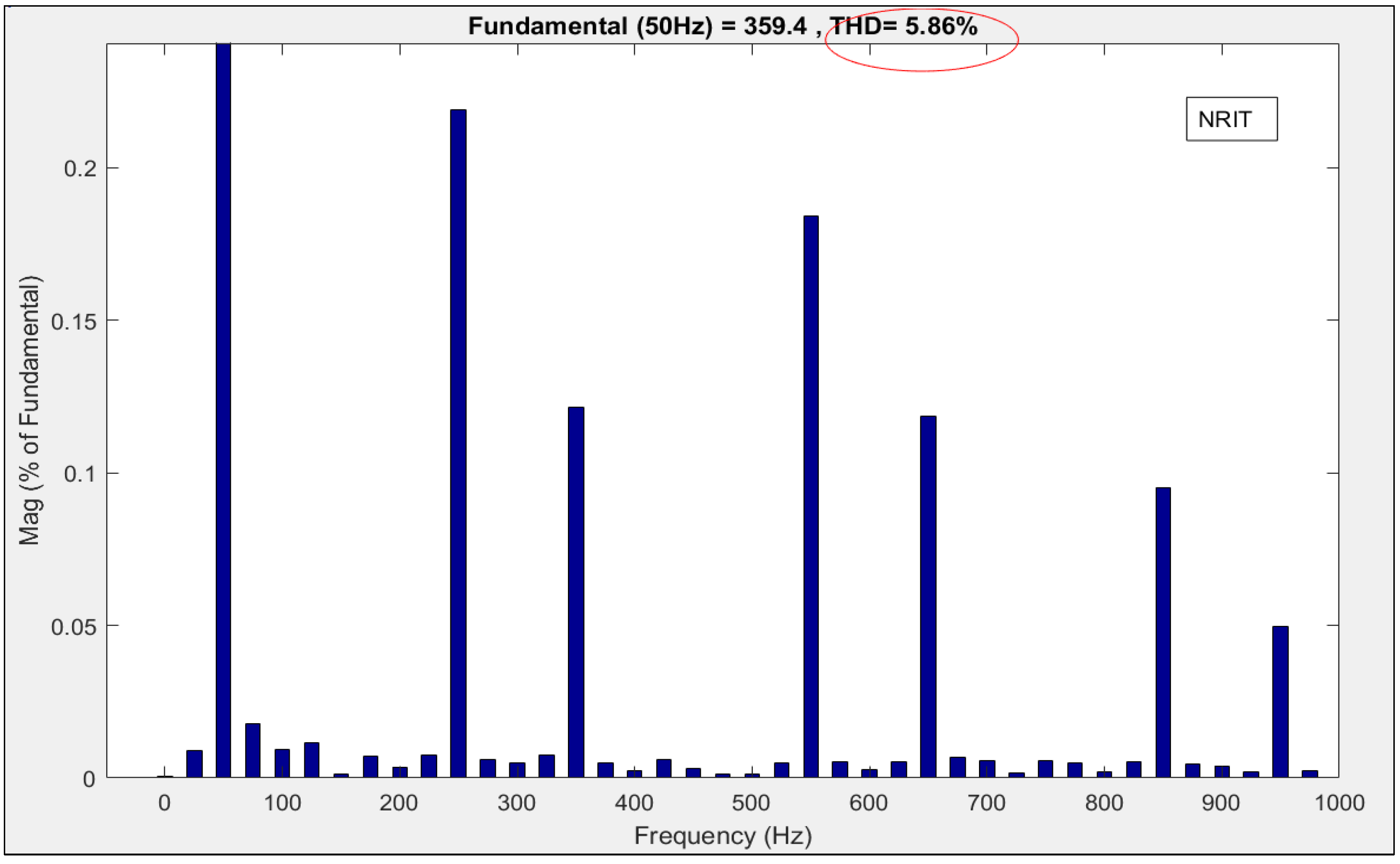
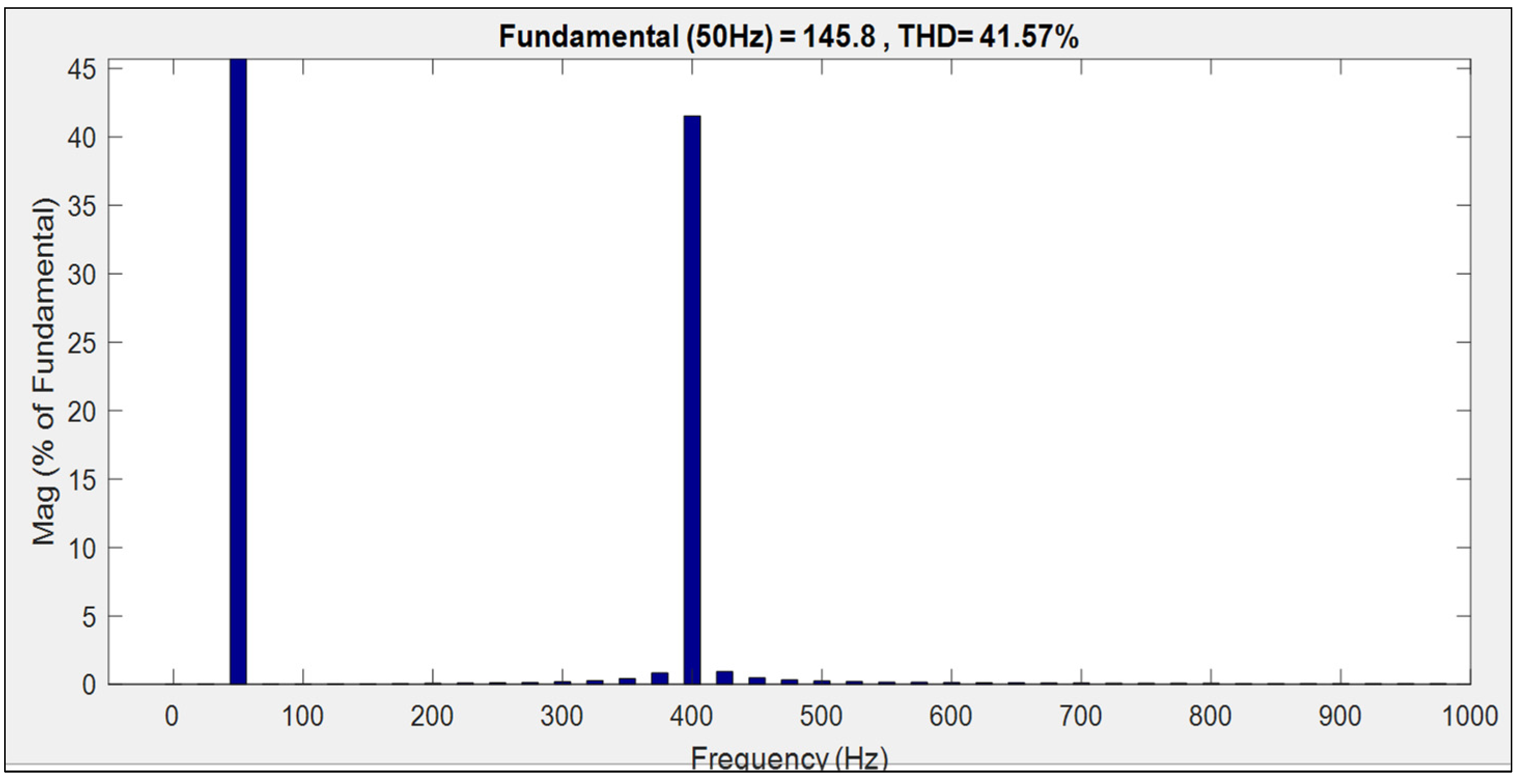
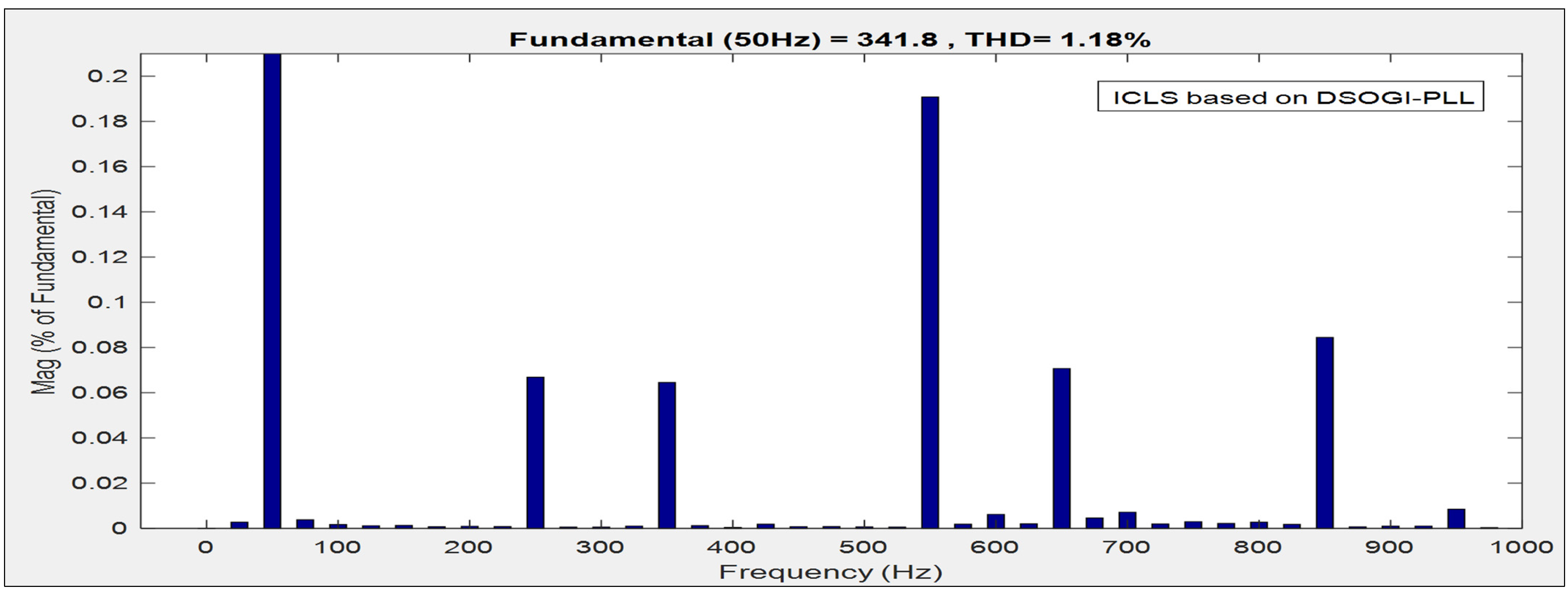
- The proposed inverter control technique is compared with other recently developed algorithms from the literature in different case studies using the fast Fourier transform (FFT) to measure the power quality of the proposed system.
2. PSC and Power Quality
2.1. Partial Shading Conditions
2.2. Power Quality
3. Grid-Tied System Description
4. The Proposed MPPT and Inverter Control Algorithm
4.1. Proposed FRMO Based on DSP MPPT
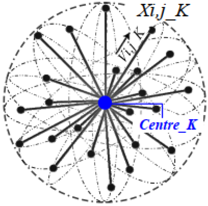
- Flexible Radial Movement Optimization
- i.
- Initialize
- ii.
- Movement
- Dynamic Safety Perimeter (DSP)
- i.
- Offline technique requires accurate current and voltage (I-V) data of the PV module characteristic.
- ii.
- Online technique requires the recorded MPP values acquired from the FRMO without PSC.
- i.
- Determine the safety region of a 1STH-215-P PV module.
- ii.
- Calculate its boundary using Equations (17)–(19).
- iii.
- Calculate the overall safety region of the series and parallel configuration using Equations (15) and (16).
- iv.
- Enumerate the online DSP by working out the optimization problem (13), depending on constraints (19) by applying (20) and (22).
- v.
- Then record the observed MPP under normal conditions and update the safety region border of the third step to obtain control of the approximation in the first and second steps.
- FRMO based on DSP.
- i.
- Measure the current and voltage values of the FRMO algorithm and calculate the PV output power.
- ii.
- The instantaneous DSP value, is determined by the current state of the PV, based on the denoted safety region
- iii.
- The system is normal when the PV state otherwise, PSC has occurred.
- iv.
- The output of FRMO is scaled based on the value of when the PV state, using Equation (24).
| Algorithm 1. Pseudo-code of FRMO-DSP. |
| Define the set of inequalities constraints in a form of |
| Input: the set of current (I) and voltage (V) historical dataset, ; |
| Output: The prediction of PV output power,; 1. History; 2. do 3. 4. 5. 6. 7. , terminate; otherwise; 8. such that 9. 10. Terminate if 11. Terminate for 12. Update y 13. End while 14. Return the current equation; |
4.2. Proposed Novel Inverter Control Loop System (ICLS) with a DSOGI-PLL
5. System Setup
6. Results and Discussion
6.1. Case Study 1
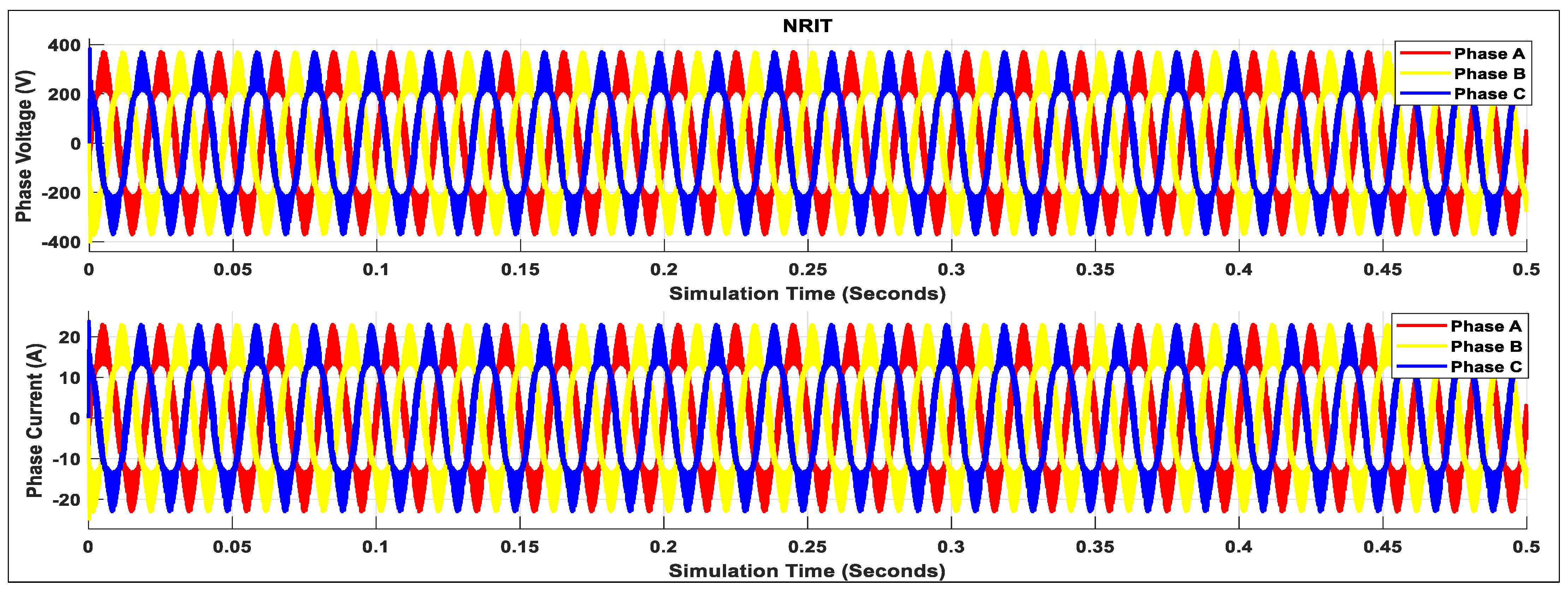
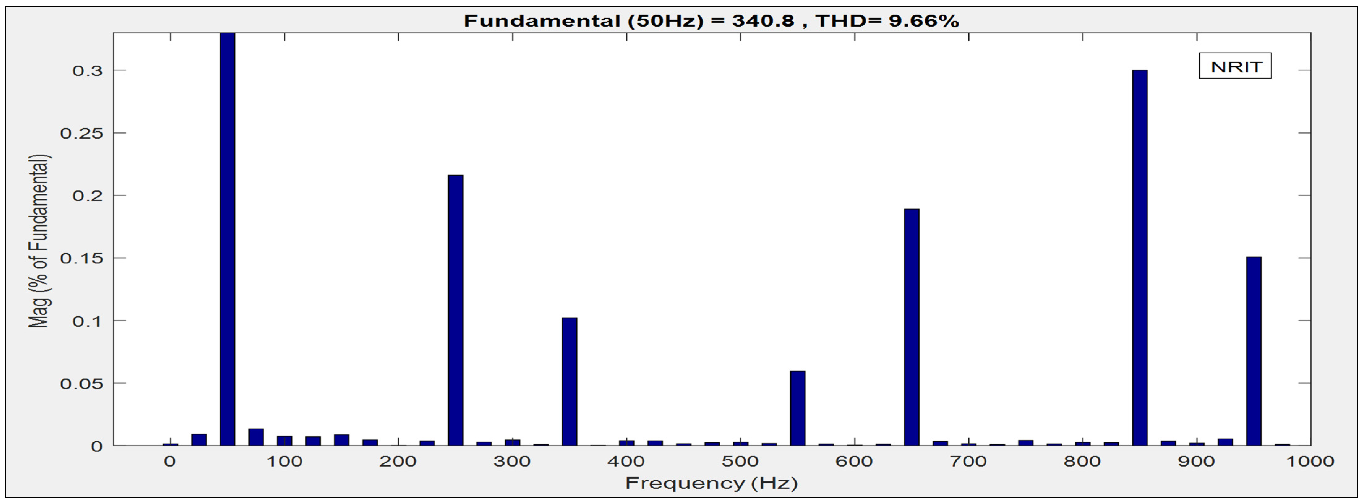
6.2. Case Study 2
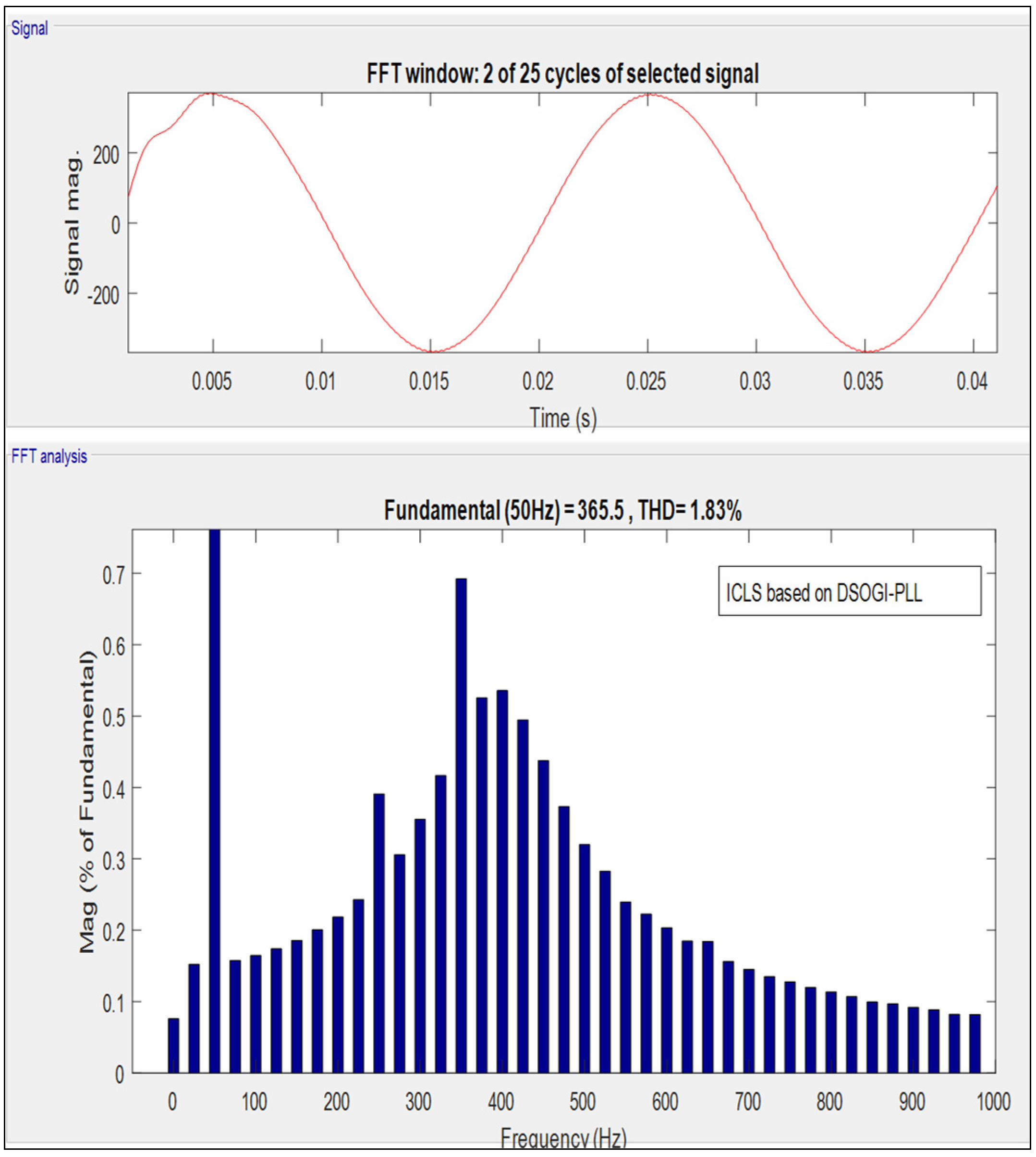
6.3. Case Study 3
6.4. Summary
7. Conclusions
Author Contributions
Funding
Institutional Review Board Statement
Informed Consent Statement
Data Availability Statement
Acknowledgments
Conflicts of Interest
References
- Kermadi, M.; Salam, Z.; Eltamaly, A.M.; Ahmed, J.; Mekhilef, S.; Larbes, C.; Berkouk, M. Recent Developments of MPPT Techniques for PV Systems under Partial Shading Conditions: A Critical Review and Performance Evaluation; IET: London, UK, 2020. [Google Scholar]
- Da Rocha, M.V.; Sampaio, L.P.; Da Silva, S.A.O. Comparative analysis of MPPT algorithms based on Bat algorithm for PV systems under partial shading condition. Sustain. Energy Technol. Assess. 2020, 40, 100761. [Google Scholar] [CrossRef]
- Gil-Velasco, A.; Aguilar-Castillo, C. A Modification of the Perturb and Observe Method to Improve the Energy Harvesting of PV Systems under Partial Shading Conditions. Energies 2021, 14, 2521. [Google Scholar] [CrossRef]
- Eltamaly, A. An Improved Cuckoo Search Algorithm for Maximum Power Point Tracking of Photovoltaic Systems under Partial Shading Conditions. Energies 2021, 14, 953. [Google Scholar] [CrossRef]
- Kermadi, M.; Salam, Z.; Ahmed, J.; Berkouk, E.M. An Effective Hybrid Maximum Power Point Tracker of Photovoltaic Arrays for Complex Partial Shading Conditions. IEEE Trans. Ind. Electron. 2019, 66, 9. [Google Scholar] [CrossRef]
- Bhukya, M.N.; Kota, V.R.; Depuru, S.R.; Reddy, M.P.P.; Reddy, G.H. Effective Design and Implementation of Hybrid MPPT Scheme Based on LT-NI Technique for PV System. IEEE Access 2021, 9, 3064936. [Google Scholar] [CrossRef]
- Padmanaban, S.; Dhanamjayulu, C.; Khan, B. Artificial Neural Network and Newton Raphson (ANN-NR) Algorithm Based Selective Harmonic Elimination in Cascaded Multilevel Inverter for PV Applications. IEEE Access 2021, 9, 3081460. [Google Scholar] [CrossRef]
- Babu, N.P.; Guerrero, J.M.; Siano, P.; Peesapati, R.; Panda, G. A Novel Modified Control Scheme in Grid-tied Photovoltaic System for Power Quality Enhancement. IEEE Trans. Ind. Electron. 2020, 68, 11100–11110. [Google Scholar]
- Kumar, V.N.; Babu, P.N.; Kiranmayi, R.; Siano, P.; Panda, G. Improved Power Quality in a Solar PV Plant Integrated Utility Grid by Employing a Novel Adaptive Current Regulator. IEEE Syst. J. 2020, 14, 3. [Google Scholar] [CrossRef]
- Mikkili, S.; Panda, A. Real-time implementation of PI and fuzzy logic controllers-based shunt active filter control strategies for power quality improvement. Int. J. Elect. Power Energy Syst. 2012, 43, 1114–1126. [Google Scholar] [CrossRef]
- Singh, A.; Negi, S.; Bhandari, S. Harmonic Minimization Using Newton Raphson Method. J. Emerg. Technol. Innov. Res. 2019, 6, 7. [Google Scholar]
- Radmanesh, H.; Dehghani, S.Y.; Sharifi, R. Using Bat Algorithm to Reduce Total Harmonic Distortion in Multi-Level Inverter. 2018, 1, 53-45. Available online: http://kiaeee.ir/article-1-141-fa.html (accessed on 24 June 2022).
- Jadidi, S.; Badihi, H.; Zhang, Y. Passive Fault-Tolerant Control Strategies for Power Converter in a Hybrid Microgrid. Energies 2020, 13, 5625. [Google Scholar] [CrossRef]
- Babu, P.N.; Babu, B.C.; Babu, P.R.; Panda, G. An optimal current control scheme in grid-tied hybrid energy system with active power filter for harmonic mitigation. Int. Trans. Elect. Energy Sys. 2020, 30, e12183. [Google Scholar]
- Rehan, A.; Bernhard, B.; Stefan, D.; Lukas, S.; Pratyush, K. Optimal power management with guaranteed minimum energy utilization for solar energy harvesting systems. ACM Trans. Embed. Comput. Syst. 2019, 18, 1–26. [Google Scholar]
- Bi, Z.; Ma, J.; Man, K.L.; Smith, J.S.; Yue, Y.; Wen, H. Global MPPT method for photovoltaic systems operating under partial shading conditions using the 0.8VOC model. In Proceedings of the 2019 IEEE International Conference on Environment and Electrical Engineering and 2019 IEEE Industrial and Commercial Power Systems Europe (EEEIC/I&CPS Europe), Genova, Italy, 11–14 June 2019; pp. 1–6. [Google Scholar]
- Pradhan, S.; Hussain, I.; Singh, B.; Panigrahi, B.K. Modified VSSLMS-based adaptive control for improving the performance of a single stage PV integrated grid system. IET Sci. Meas. Technol. 2017, 11, 388–399. [Google Scholar] [CrossRef]
- Babu, P.N.; Babu, P.R.; Panda, G. An adaptive differentiation frequency based advanced reference current generator in grid-tied PV applications. IEEE J. Emerg. Sel. Topics Power Electron. 2020, 8, 3502–3515. [Google Scholar] [CrossRef]
- Ramyar, A.; Iman-Eini, H.; Farhangi, S. Global maximum power point tracking method for photovoltaic arrays under partial shading conditions. IEEE Trans. Ind. Electron. 2017, 64, 2855–2864. [Google Scholar] [CrossRef]
- Eltamaly, A.; Al-Saud, M.; Abokhalil, A.G.; Farh, H.M. Simulation and experimental validation of fast adaptive particle swarm optimization strategy for photovoltaic global peak tracker under dynamic partial shading. Renew. Sustain. Energy Rev. 2020, 124, 109719. [Google Scholar] [CrossRef]
- Tajuddin, M.F.N.; Ayob, S.M.; Salam, Z. Tracking of Maximum Power Point in Partial Shading Conditions using Differential Evolution (DE). In Proceedings of the 2012 IEEE International Conference on Power and Energy (PECon), Kota Kinabalu, Malaysia, 2–5 December 2012. [Google Scholar]
- Abdel-Geliel, M. Fault Diagnosis and Performance Recovery Based on Dynamic Safety Margin. Ph.D. Dissertation, Mannheim University, Mannheim, Germany, 2006. [Google Scholar]
- Mishra, S.; Ray, P.K. Power quality improvement using photovoltaic fed DSTATCOM based on JAYA optimization. IEEE Trans. Sustain. Energy 2016, 7, 1672–1680. [Google Scholar] [CrossRef]
- Golestan, S.; Guerrero, J.M.; Vasquez, J.; Abusorrah, A.M.; Al-Turki, Y.A. A study on three-phase FLLs. IEEE Trans. Power Electron. 2019, 34, 213–224. [Google Scholar] [CrossRef] [Green Version]
- Guest, E.; Mijatovic, N. Discrete-time complex band pass filters for three-phase converter systems. IEEE Trans. Ind. Electron. 2019, 66, 4650–4660. [Google Scholar] [CrossRef]
- Golestan, S.; Guerrero, J.M.; Vasquez, J.C. Is using a complex control gain in three-phase FLLs reasonable? IEEE Trans. Ind. Electron. 2020, 67, 2480–2484. [Google Scholar] [CrossRef]


| Zone | SW 1 | SW 2 | SW 3 |
|---|---|---|---|
| 1 | |||
| 2 | |||
| 3 | |||
| 4 | |||
| 5 | |||
| 6 |
| PV Model | 1STH-215-P |
|---|---|
| PV rated Power | 213.15 W |
| Vmpp | 29 V |
| Impp | 7.35 A |
| Number of cells in series (Ns) | 60 |
| Series resistance (Rs) | 0.39383 Ω |
| Shunt resistance (Rsh) | 313.3991 Ω |
| L1 (DC link inductor) | 100 mH |
| C1 | 100 µF |
| C2 | 100 µF |
| Ro | 20 Ω |
| C3 (DC Link Capacitor) | |
| DC link Voltage | 24–38 VDC |
| LC Filter | |
| Controller sampling frequency | 20 kHz |
| Inverter input VDC | 24–40 Vdc |
| Inverter Output VAC | 380 Vac (±5%)—3 phase |
| Grid nominal voltage | 380 Vac |
| Grid nominal current | 25 A |
| Grid local power | 0.2 kW |
| Grid nominal Frequency | 50 Hz |
| Weather Conditions | Temperature (°C) | DC-Link Inductor | Load | |
|---|---|---|---|---|
| Case Study 1 | G1 = 1000 | T1 = 25 | L = 100 mH | 100 W |
| G2 = 850 | T2 = 31 | |||
| G3 = 900 | T3 = 27 | |||
| G4 = 920 | T4 = 19 | |||
| Case Study 2 | G1 = 1000 | T1 = 25 | L = 80 mH | 100 W to 150 W |
| G2 = 690 | T2 = 27 | |||
| G3 = 835 | T3 = 21 | |||
| G4 = 740 | T4 = 30 | |||
| Case Study 3 | G1 = 950 | T1 = 25 | L = 50 mH | 100 W to 180 W |
| G2 = 750 | T2 = 22 | |||
| G3 = 670 | T3 = 32 | |||
| G4 = 800 | T4 = 17 |
| FRMO-DSP MPPT | ||||
|---|---|---|---|---|
| Case Study | DC Link Voltage (V) | PV Power (W) | Tracking Time (s) | PV Efficiency (%) |
| 1 | 28.9 | 212.89 | 0.02 | 99.88 |
| 2 | 28.4 | 208.93 | 0.12 | 98.02 |
| 3 | 29.1 | 207.9 | 0.13 | 97.54 |
| ICLS Based on DSOGI-PLL | NRIT | |||||
|---|---|---|---|---|---|---|
| Case Study | THD (%) | System PF | Settling Time (s) | THD (%) | System PF | Settling Time (s) |
| 1 | 0.46% | 0.999 | 0.18 | 5.86% | 0.998 | 0.32 |
| 2 | 1.18% | 0.999 | 0.25 | 9.66% | 0.995 | 0.47 |
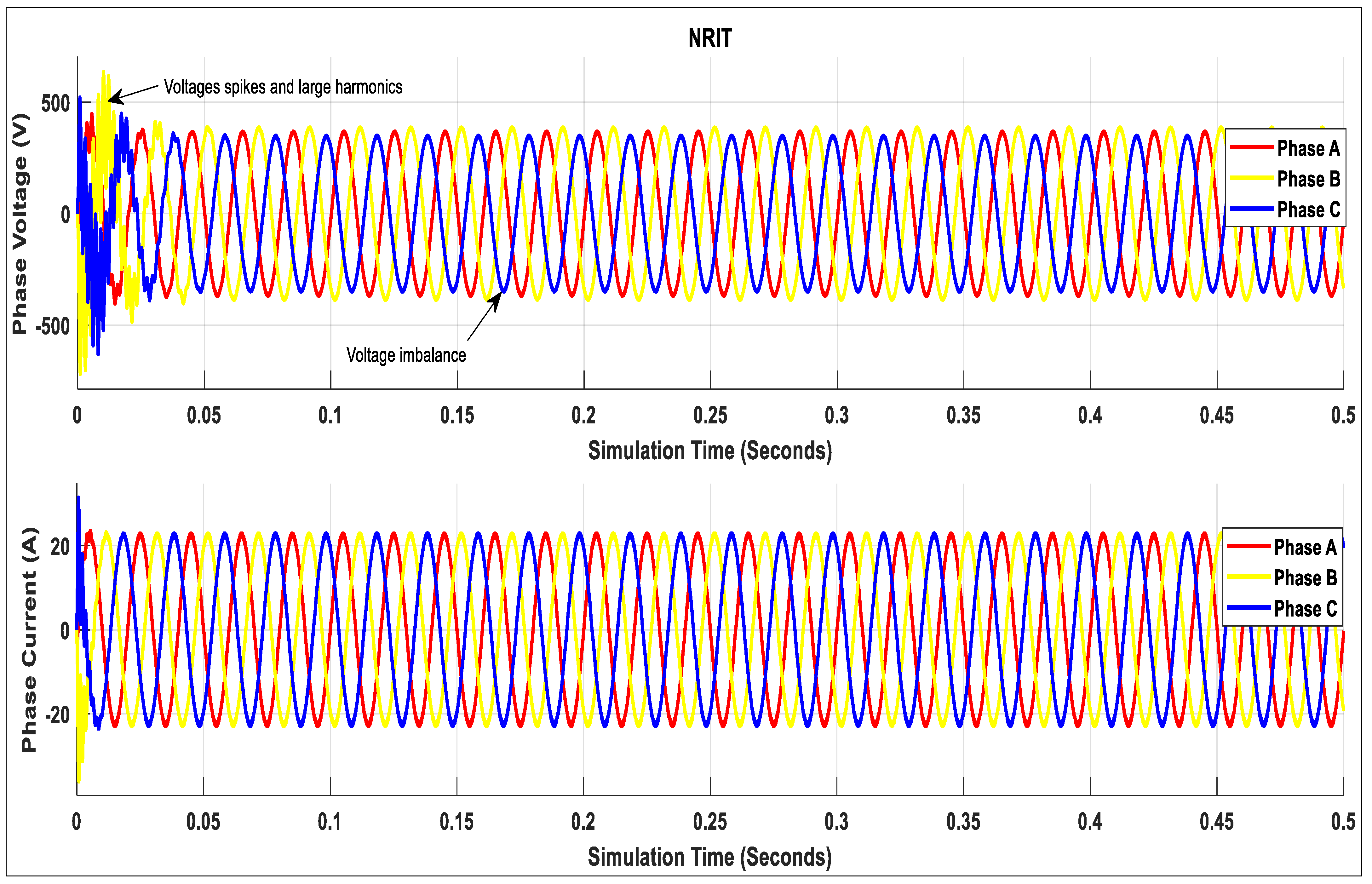
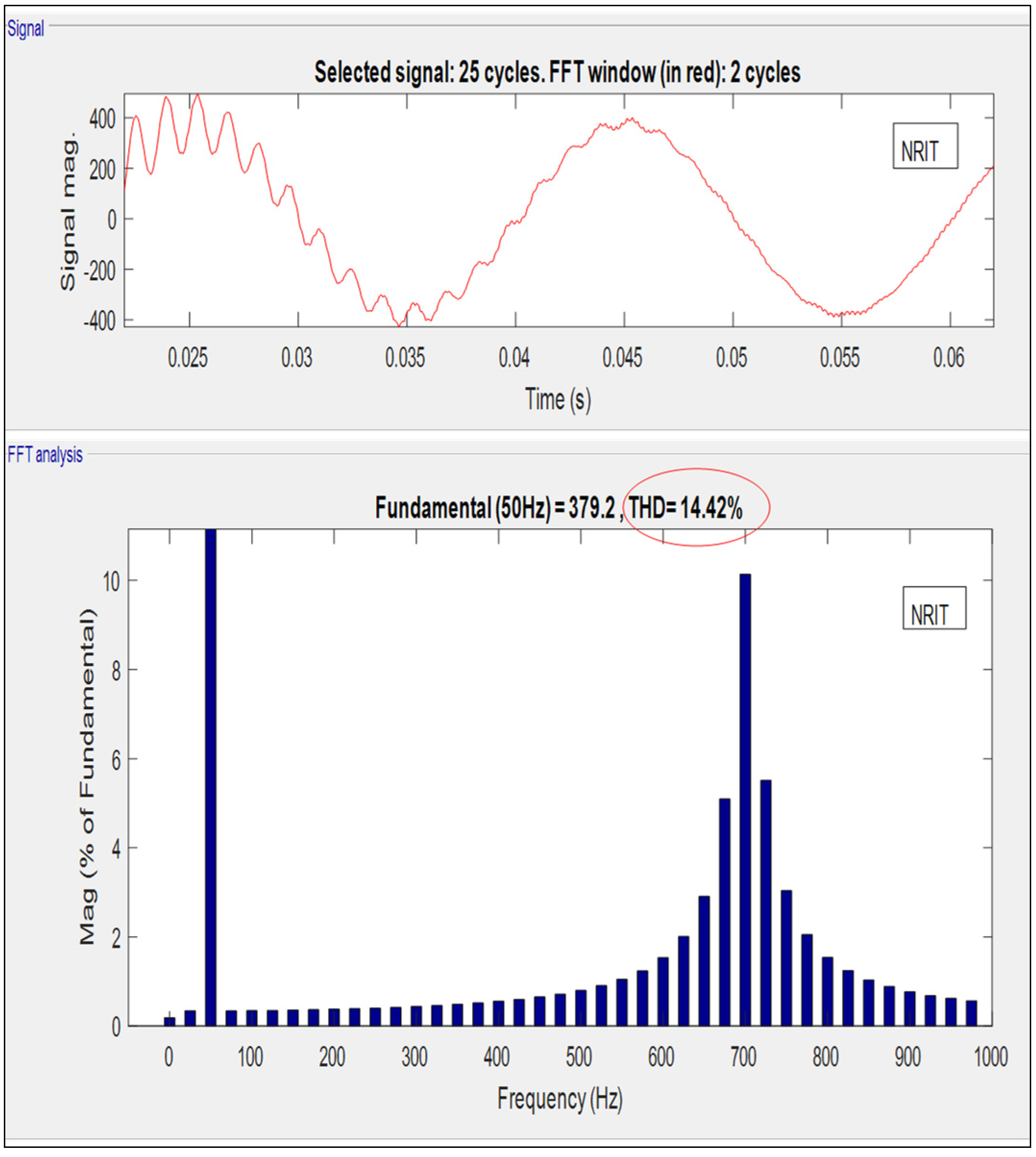
| 3 | 1.83% | 0.997 | 0.27 | 14.42% | 0.979 | 0.51 |
| Parameters | NRIT-PLL | Proposed DSOGI-PLL |
|---|---|---|
| Settling time | 0.17 s | 0.06 s |
| Frequency overshoot | 36% | 5% |
| Phase overshoot | 30° | 8° |
| Grid synchronization speed | 5 s | 0.05 s |
| Steady-state convergence | 0.028 s | 0.011 s |
| Sampling time | 50 μs | 50 μs |
| Average system TDD of grid currents | 9.98% | 1.16% |
| Characteristics | NRIT | ICLS-DSOGI-PLL |
|---|---|---|
| Type of filter | Adaptive | Adaptive |
| Oscillations | Moderate | Very less |
| Complexity | Medium | less |
| Amplitude tracking | Good | Excellent |
| Grid Synchronization | Yes | Yes |
| Accuracy | Moderate | Better |
| Frequency tracking | Good | Better |
| Settling time | high | less |
| THD under linear load | Moderate | Very less |
| THD under nonlinear load | Exceeds IEEE 519 limits | Very less |
Publisher’s Note: MDPI stays neutral with regard to jurisdictional claims in published maps and institutional affiliations. |
© 2022 by the authors. Licensee MDPI, Basel, Switzerland. This article is an open access article distributed under the terms and conditions of the Creative Commons Attribution (CC BY) license (https://creativecommons.org/licenses/by/4.0/).
Share and Cite
Nkambule, M.S.; Hasan, A.N.; Ali, A.; Shongwe, T. A Novel Control Strategy in Grid-Integrated Photovoltaic System for Power Quality Enhancement. Energies 2022, 15, 5645. https://doi.org/10.3390/en15155645
Nkambule MS, Hasan AN, Ali A, Shongwe T. A Novel Control Strategy in Grid-Integrated Photovoltaic System for Power Quality Enhancement. Energies. 2022; 15(15):5645. https://doi.org/10.3390/en15155645
Chicago/Turabian StyleNkambule, Mpho Sam, Ali N. Hasan, Ahmed Ali, and Thokozani Shongwe. 2022. "A Novel Control Strategy in Grid-Integrated Photovoltaic System for Power Quality Enhancement" Energies 15, no. 15: 5645. https://doi.org/10.3390/en15155645
APA StyleNkambule, M. S., Hasan, A. N., Ali, A., & Shongwe, T. (2022). A Novel Control Strategy in Grid-Integrated Photovoltaic System for Power Quality Enhancement. Energies, 15(15), 5645. https://doi.org/10.3390/en15155645