Article

Experimental Study on the Distribution Characteristics of CO2 in Methane Hydrate-Bearing Sediment during CH4/CO2 Replacement

1
Key Laboratory of Gas Hydrate, Ministry of Natural Resources, Qingdao Institute of Marine Geology, Qingdao 266237, China
2
Laboratory for Marine Mineral Resources, Pilot National Laboratory for Marine Science and Technology, Qingdao 266237, China
3
College of Physics and Opto-Electronic Engineering, Ocean University of China, Qingdao 266100, China
*
Authors to whom correspondence should be addressed.
Energies 2022, 15(15), 5634; https://doi.org/10.3390/en15155634
Submission received: 28 June 2022 / Revised: 27 July 2022 / Accepted: 2 August 2022 / Published: 3 August 2022
(This article belongs to the Special Issue Gas Hydrate Energy Technologies for Net-Zero Carbon Emissions)

Abstract

:
CH4/CO2 replacement is of great significance for the exploitation of natural gas hydrate resources and CO2 storage. The feasibility of this method relies on our understanding of the CH4/CO2 replacement efficiency and mechanism. In this study, CH4/CO2 replacement experiments were carried out to study the distribution characteristics of CH4 and CO2 in hydrate-bearing sediments during and after replacement. Similar to previously reported data, our experiments also implied that the CH4/CO2 replacement process could be divided into two stages: fast reaction and slow reaction, representing CH4/CO2 replacement in the hydrate-gas interface and bidirectional CH4/CO2 diffusion caused replacement, respectively. After replacement, the CO2 content gradually decreased, and the methane content gradually increased with the increase of sediment depth. Higher replacement percentage can be achieved with higher replacement temperature and lower initial saturation of methane hydrate. Based on the calculation of CO2 consumption amounts, it was found that the replacement mainly took place in the fast reaction stage while the formation of CO2 hydrate by gaseous CO2 and water almost runs through the whole experimental process. Thus, the pore scale CH4/CO2 replacement process in sediments can be summarized in the following steps: CO2 injection, CO2 diffusing into sedimentary layer, occurrence of CH4/CO2 replacement and CO2 hydrate formation, wrapping of methane hydrate by mixed CH4-CO2 hydrate, continuous CO2 hydrate formation, and almost stagnant CH4/CO2 replacement.

1. Introduction

Natural gas hydrate (mainly methane hydrate) widely occurs in the seabed on the continental margin and permafrost area [1]. The huge reserves of natural gas hydrate make it an alternative energy source. Thus, hydrate production method research and field pilot production tests are attracting worldwide attention [2]. At present, the main hydrate exploitation methods include depressurization, heat stimulation, chemical additive injection, and CO2 replacement [3,4,5,6,7]. Among the above methods, depressurization has long been considered as the most feasible method in field exploitation, even though there are still risks of sand production, formation instability, and production stagnation for long-term mining. In recent years, a CH4/CO2 replacement method has attracted worldwide interests as a win-win method for simultaneous CH4 recovery and CO2 storage, captured by absorption, adsorption, and membrane separation [8,9,10,11]. The feasibility of gas production from hydrate by CH4/CO2 replacement was first confirmed by Ohgaki et al. [12]. The replacement of CH4 from methane hydrate by CO2 is thermodynamically and kinetically feasible by obtaining −3.49 kJ/mol for the Gibbs free energy [13,14,15,16]. As CO2 hydrate is more stable than CH4 hydrate at the same temperature and pressure, the CH4/CO2 replacement method for hydrate production can maintain the mechanical stability of the sediments [17,18]. In 2012, a CH4/CO2 replacement method was adopted in a test production of natural gas hydrate conducted in Alaska [19,20]. The production results proved the theoretical feasibility of this method. Unfortunately, the low replacement efficiency restricted the practical application.
Owing to the advantages in stabilizing the hydrate reservoir and CO2 storage and the low efficiency in the practical production test of CH4/CO2 replacement, studies have been extended to enhance the replacement rate and efficiency and to explore the replacement mechanism in the laboratory. In order to improve the replacement efficiency of CO2 replacement, factors such as replacement conditions (pressure and temperature), CO2 injection state, and sediment characteristics that may affect the replacement efficiency have been studied by many researchers [5,9,21,22,23,24]. Chen et al. [25] suggested that temperature had a great influence on CH4/CO2 replacement. At higher temperature, decomposition and replacement may exist simultaneously [26]. Moreover, the influence of temperature is related to the freezing point of water. For example, if the temperature is higher than the freezing point, the replacement efficiency increases with the increase of temperature; while if the temperature is lower than the freezing point, an ice layer may form on the hydrate surface, which may result in a relatively slow replacement process [27,28]. The state of CO2 is also an essential factor affecting the replacement efficiency. At the same P-T condition, injection of gaseous CO2, liquid CO2, CO2 emulsion, and supercritical CO2 into methane hydrate results in the following replacement efficiency ranking: supercritical CO2 > emulsion CO2 > liquid CO2 > gaseous CO2 [22,29,30,31,32]. Ota et al. [33] found that the replacement reaction was promoted by an increase in pressure from 3.2 to 3.6 MPa. However, no change was observed at higher pressures because of CO2 liquefaction. Several studies also demonstrated that injecting a certain proportion of N2–CO2 gas mixture could improve the replacement rate [34,35,36]. It was proposed that the external N2 molecules specifically would attack the CH4 molecules already entrapped in a small cage and play a significant role in substantially increasing the CH4 recovery rate [34]. It was also found that minerals with small particle size (for example clay minerals) could significantly reduce the permeability of sediments, and result in lower CH4/CO2 replacement efficiency [9]. These studies have shown that optimizing CO2 injection conditions can improve the displacement efficiency effectively. Moreover, researchers also studied the replacement efficiency of the combined production methods, for example, CH4/CO2 injection and depressurization, CH4/CO2 injection and heat stimulation, and injection of both CH4/CO2 and chemical additives (such as NaCl, surfactant, etc.). The combined production methods were found to be favorable in improving the CH4/CO2 replacement efficiency [37,38,39,40,41,42,43].
When discussing the reasons for the low replacement efficiency, it is generally believed that the CH4/CO2 replacement starts at the surface of methane hydrate, which hinders further diffusion of CO2 and the occurrence of replacement. Lee et al. [16] and Bai et al. [44] proposed that the replacement rate gradually decreased as the CO2-CH4 mixed hydrate gradually formed, which decreased the diffusivity of the CO2 through the preformed hydrate layer. However, this may not be the case for hydrate reservoirs. With the injection of CO2 in sediments, they may quickly form a CO2 hydrate layer which prevents the further penetration of gaseous CO2. Therefore, the vertical diffusion of CO2 in CH4 hydrate bearing sediments is essential in determining the vertical displacement degree of CO2, which is of theoretical significance for further understanding the displacement process. Although a number of previous CO2 replacement experiments have been carried out to examine the factors affecting the replacement efficiency, there is still a lack of theoretical discussion on the CO2 replacement efficiency with regard to the vertical diffusion process of CO2 in a methane hydrate reservoir. In this study, experiments were conducted in a pressure vessel with sea sand as sediment media. Different from previous works, the sediment samples were carefully examined layer by layer after replacement, aiming to study the vertical distribution and diffusion characteristics of CO2 in the process of replacement, as well as the influence of factors that affect the replacement efficiency including replacement temperature and initial CH4 hydrate saturation.

2. Materials and Methods

2.1. Experimental Apparatus

The experimental system (Figure 1) consists of a cylindrical pressure vessel, a reactant-supply module for gas injecting, a thermostatic chamber, a gas chromatograph (GC), and a data-acquisition module. The main body of the pressure vessel is made of stainless steel with a pressure tolerance of 30 MPa and equipped with two temperature sensors and one pressure sensor. The effective volume of the vessel is 120 mL. The GC (ThermoGC1100) is connected to the pressure vessel through two valves to measure the gas components in the vessel during the replacement. After replacement, the recovered gas of each sample slice is also analyzed by GC. The pressure vessel is situated in the thermostatic chamber with a temperature controlling range of −30 °C to 25 °C. The temperature fluctuation during experiments is lower than 0.1 °C.

2.2. Experimental Procedure

2.2.1. Sample Preparation

The cylindrical pressure vessel and the associated inner cylinder sample holder (inner diameter 35 mm) were carefully washed with deionized water and dried. Then selected sea sand (grain size ranges from 0.15 mm to 0.25 mm) were evenly mixed with a certain amount of deionized water (water saturation is 30–35%). After that, water bearing sea sand of a total volume of 60 mL was added into the sample holder and the sample holder was placed in the pressure vessel. The pressure vessel was then sealed and put under vacuum. Based on the required hydrate saturation of a single experiment, CH4 gas was injected into the pressure vessel to a certain pressure and maintained for 24 h. The pressure vessel was then cooled to 1.5 °C to form CH4 hydrate until the pressure remained unchanged for at least 12 h. To ensure the reliability of the experimental results, the distribution uniformity of methane hydrate in the sample before replacement was examined in the following steps. First, a methane hydrate-bearing sample was prepared with exactly the same procedure as described above. Then the sample was sliced into two pieces horizontally with the protection of liquid nitrogen, and the upper and lower parts were scanned by nano-focus X-ray computed tomography (X-CT, Phoenix X-ray v|tome|xs, GE Sensing & Inspection Technologies, Wunstorf, Germany). A self-developed container with controllable temperature and pressure was used for X-CT analysis, which can maintain the stability of the hydrate during CT scanning. The X-CT data were analyzed with VG Studio MAX. The detailed X-CT measurement and analytical method were followed exactly as that reported in Li et al. [45,46].

2.2.2. CH4/CO2 Replacement

(1)
CO2 injection: After the formation of CH4 hydrate, the pressure vessel was cooled down to −20 °C and held for at least 1 h. CH4 gas in the vessel was released within 10 s and CO2 was re-injected until the pressure reached ~3.5 MPa. To avoid hydrate dissociation, CO2 was precooled in the cold-water buffer tank before injection. Then the vessel was heated to a certain temperature, and this specific point in time was recorded as the start of the replacement process.
(2)
In situ analysis: Straight after the re-injection of CO2, the valves between the pressure vessel and the GC were opened and closed in turn to allow a small volume of gas (less than 0.2% v/v of the pressure vessel) in the pressure vessel to be sampled, so that the initial gas composition in the pressure vessel could be determined. The same method was conducted to obtain the gas composition in the pressure vessel every 24 h until the end of the experiments, which lasted for 12 days.
(3)
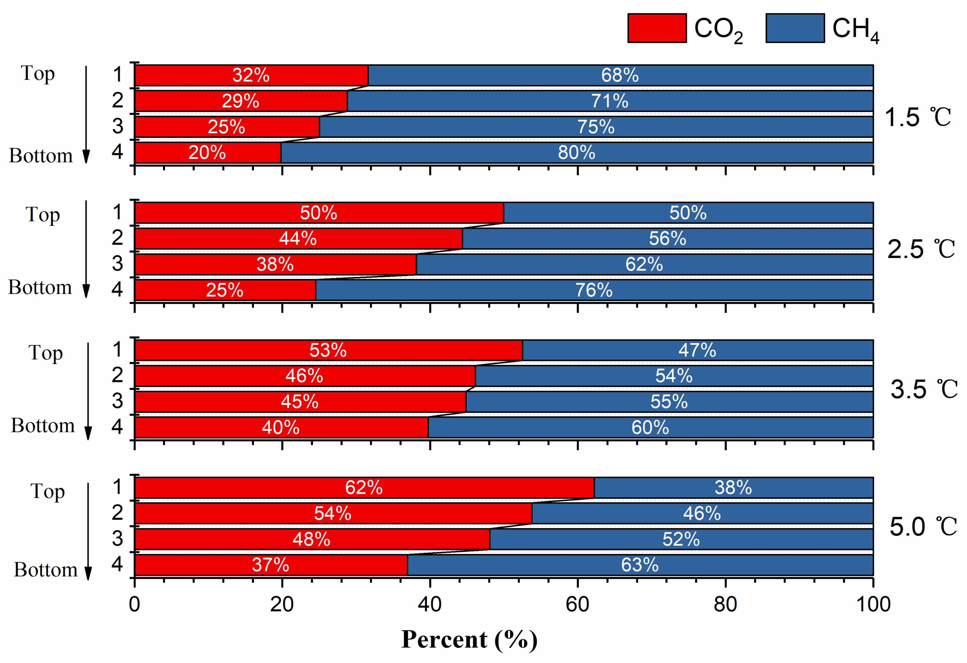
Sample slicing: After replacement, hydrate-bearing sample in the pressure vessel was taken out and sliced into four pieces horizontally under the protection of liquid nitrogen (Figure 2). The composition of the decomposed gas for each sample piece was collected and analyzed by GC.
The replacement conditions are summarized in Table 1 below.

2.3. Calculation Methods

2.3.1. Hydrate Saturation

The amount of formed methane hydrate in our experiments was determined according to the amount of methane gas consumed in the process of hydrate formation. Assuming that the density of methane hydrate is the same as the value reported previously [47], then the saturation of hydrate can be calculated by using the porosity of the sediments. The formula to calculate the saturation of hydrate is shown in Equation (1):
S h = P 1 Z 1 T P 2 Z 2 T × V g R × M h ρ h V p
where S h is the saturation of gas hydrate (the volume ratio of gas hydrate and pore space) in our sample prepared in the pressure vessel; M h is the molar mass of gas hydrate, taking CH4 hydrate for example, the value of M h is 122.02 g/mol if the hydration index of methane hydrate is 5.89; ρ h is the density of gas hydrate, which is 0.91 g/mL in the current calculation; V p is the total volume of pore space of the sediment sample; V g is the volume of gas phase in the reactor; T is the replacement temperature; P 1 is the initial pressure of the system; P 2 is the pressure after hydrate formation; R is the ideal gas constant, which is 8.314 J/(mol·K); Z 1 and Z 2 are the gas compressibility factors at P 1 and P 2 , respectively.

2.3.2. Replacement Efficiency

The replacement efficiency γ is calculated by the following formula:
γ = n C H 4 n C H 4 H y d r a t e
where n C H 4 is the mole number of methane in the gaseous phase in the pressure vessel; n C H 4 , H y d r a t e is the mole number of methane in the hydrate phase before replacement.

3. Results and Discussion

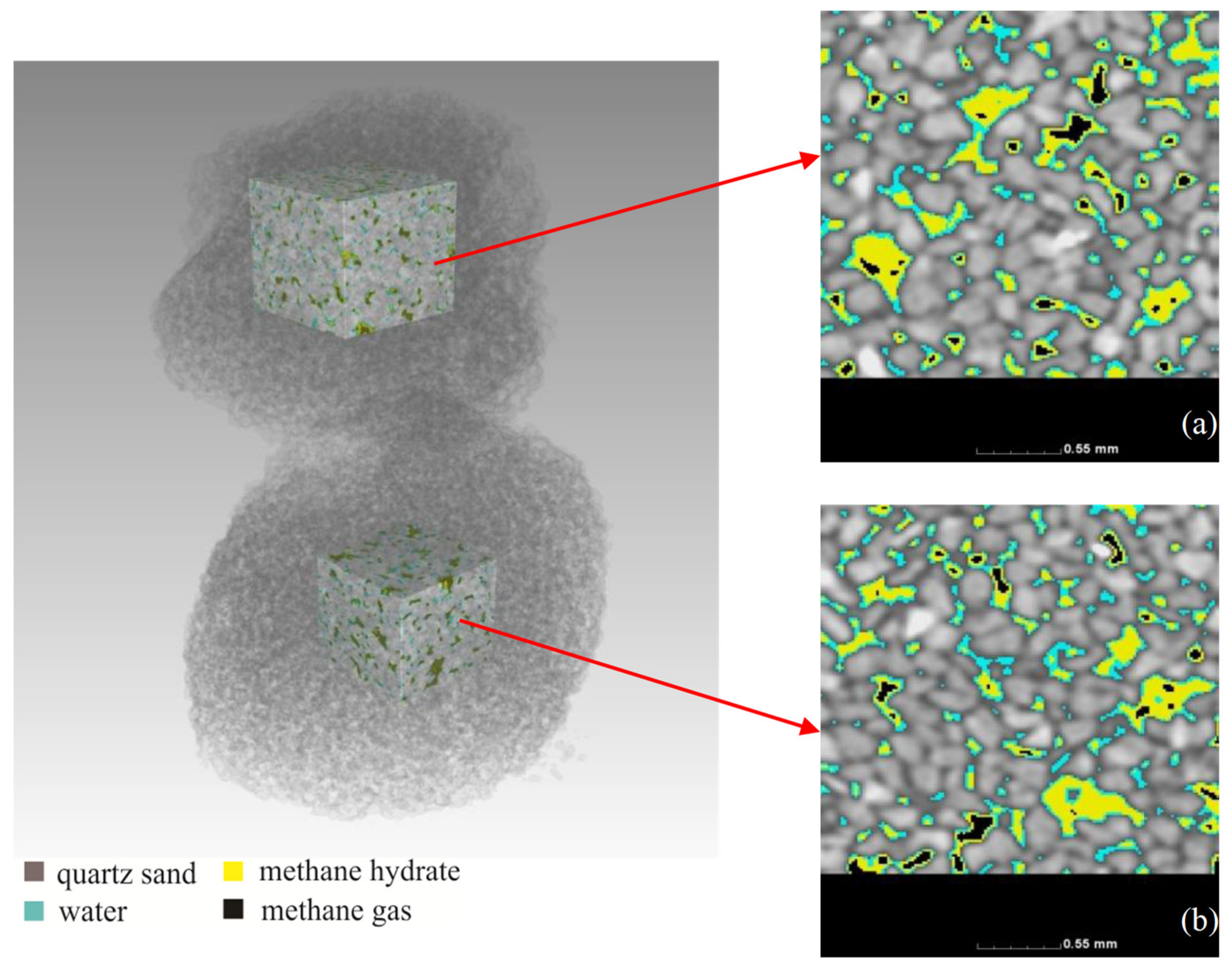
3.1. Distribution of Methane Hydrate before Replacement

Since the CO2/CH4 replacement can be highly affected by the spatial distribution of methane hydrate in sediments, the study of the vertical distribution of CO2 requires an even distribution of methane hydrate in the sediment sample. Therefore, to ensure the reliability of the experimental results, the distribution of methane hydrate in our sample before replacement was examined. The spatial distribution of methane hydrate in the prepared sediment sample is shown in Figure 3. Since the methane hydrate was formed in the selected sea sand, it was mainly formed in the pore space of the sample and was unlikely to form relatively larger clumps (Figure 3). We used the sediment porosity and hydrate saturation as criteria to examine the distribution uniformity of methane hydrate. Through three-dimensional data reconstruction and gray threshold segmentation of the scanned CT image, the gray ranges of gas, water, hydrate, and sediment were obtained [46]. Then, by calculating the volume proportion of each component, the porosity and hydrate saturation of the sample were estimated. The X-CT image analysis results showed that the porosity and the hydrate saturation of the upper and lower slice were 38.2%, 44.6% and 38.4%, 43.2%, indicating uniform spatial distribution of methane hydrate in the sediment sample. Therefore, it was reasonable for us to use the hydrate-bearing sample to study the influence factors of CH4/CO2 replacement and the distribution characteristics of CO2.

3.2. Influencing Factor of Replacement Efficiency

3.2.1. Temperature

Based on the results of GC measurement; the CO2/CH4 replacement percentages during experiments with similar initial hydrate saturation were calculated and are shown in Figure 4. For all the four experiment runs; the replacement process can be divided into two stages according to the replacement rate. The first stage starts from the beginning of the experiment and lasts for about 3 days. The replacement percentage reached over 80% of the final replacement percentage. The second stage begins from Day 4 to Day 12; when the replacement percentage showed quite a slight increase. This two-stage replacement process has been reported in many previous studies [21,48]. The rapid reaction stage refers to fast surface reactions; and the second stage with low reaction rate was due to the hinderance of CO2 diffusion by the formation of the mixed CO2-CH4 hydrate layer on the surface of methane hydrate.
At the end of the replacement experiment, the overall replacement percentages were 11.1%, 18.9%, 24.1%, and 29.0% at 1.5 °C, 2.5 °C, 3.5 °C, and 5.0 °C, respectively. Higher temperature results in relatively higher replacement percentage. Our results are consistent with previous studies of the effect of thermal stimulation on CH4/CO2 replacement [25,26]. Noting that the replacement P-T conditions of all our experiments were below the equilibrium point of methane hydrate, the replacement reaction would inevitably be accompanied by the dissociation of methane hydrate. Previous experiments [16] have shown that CO2/CH4 replacement always occurred with the dissociation of methane hydrate, then the released methane gas could mix with CO2 and reform CO2-CH4 hydrate. Since higher temperature is favorable for methane hydrate to dissociate and release methane gas, the higher dissociation rate resulting by higher temperature would benefit CO2/CH4 replacement and eventually lead to higher replacement percentage.

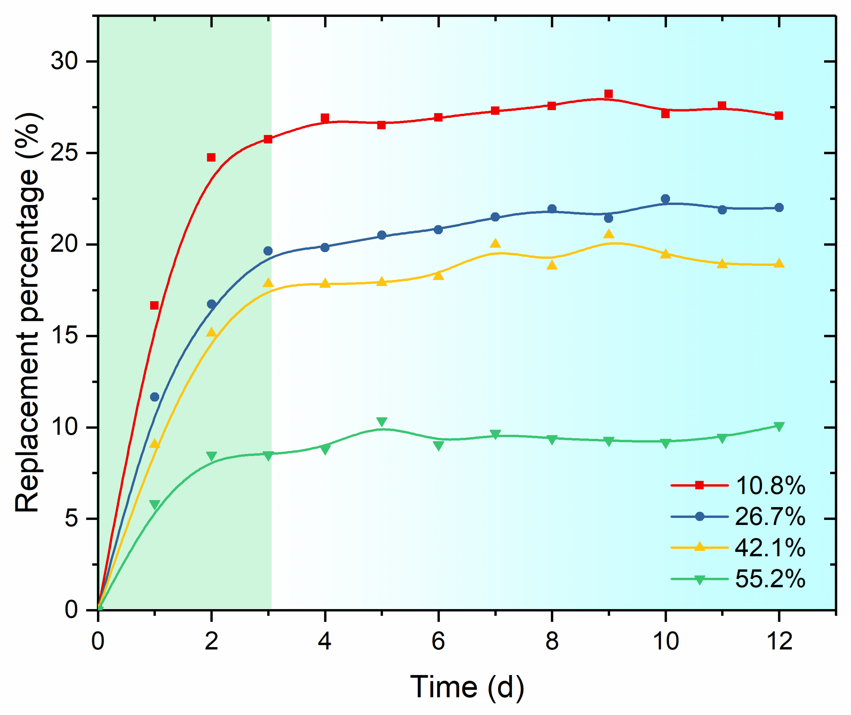
3.2.2. Initial Hydrate Saturation

The variation of CO2 replacement percentage with time for different initial methane hydrate saturations is shown in Figure 4. Similar with the temperature-controlled experiments, the replacement process can also be divided into fast stage and slow stage at the same time point (72 h). The replacement percentage of the experiment also reached about 80% of the final value. Meanwhile, the increasing rate of the replacement percentage is negatively corelated with the initial hydrate saturation (Figure 5). Samples with lower initial hydrate saturation result in greater replacement percentage. After 12 days’ replacement, the CO2 replacement percentages corresponding to 10.8%, 26.7%, 42.1%, and 55.1% initial hydrate saturation are 27.2%, 22.0%, 18.9%, and 10.1%, respectively. Such a trend in replacement percentage has also been reported by Yuan et al. [49]. Although they performed replacement experiments with liquid CO2 at relatively higher pressure, the experimental results also showed an increasing replacement percentage of CH4 hydrate with the decrease of hydrate saturation and the increase of water saturation.
Despite the highest replacement percent, the CO2/CH4 replacement experiment conducted with lowest hydrate saturation generated the lowest amount of CH4 production. Previous studies [16] have shown that the fast reaction stage of replacement is closely related with the surface reaction. Therefore, surface area (i.e., hydrate–CO2 contact area) would probably act as an important factor in determining the amount of produced CH4 in the fast reaction stage. In the current study, methane hydrate was formed in the porous sand media. With increasing hydrate saturation in the sediment sample, there must be a bottleneck in the growth of the hydrate surface area with this increasing hydrate saturation (shown in Figure 6). This is probably the reason why the amount of recovered CH4 gas did not linearly increase with the initial hydrate saturation. When the initial methane hydrate saturation exceeded ~42% in our experiments, the overall area of hydrate–gas interface probably became smaller owing to the agglomeration of hydrate particles in the pore space. As a result, the total amount of recovered CH4 gas in the experiment with highest initial hydrate saturation was not the largest.

3.3. Vertical Distribution of CO2

As discussed in Section 3.1, methane hydrate in our samples before replacement was evenly distributed in the pore space. In addition, the injection of CO2 was performed on top of the sediment sample. Therefore, the pore structure of the hydrate-bearing sample may affect the distribution of CO2 and CH4 along the direction of CO2 permeation. The vertical distribution characteristics of CO2 and CH4 for each sample after replacement are shown in Figure 7 and Figure 8. For most experiments, the CO2 molar percentage gradually decreased and the CH4 molar percentage gradually increased with the increase of sediment depth. When comparing the gas contents in slices at the same sample location in different experiments, the contents of CO2 increase with higher temperature and lower initial hydrate saturation, whereas the contents of CH4 decrease with higher temperature and lower initial hydrate saturation. The above distribution character is consistent with the penetration order of CO2 through the sample. With the injection of CO2, hydrate in the upper part of the sample started to react first. The dissociation of methane hydrate and reformation of the mix CO2/CH4 have a chance to reduce the sediment porosity and permeability, and subsequently slow down the CH4/CO2 replacement rate in the lower sediment layers. However, such a hinderance seems not strong enough to prevent the penetration of CO2 through the sediments completely. This phenomenon is probably caused by both the relatively larger pore size and the smaller vertical height of the sediment sample.

3.4. The Excess Consumption of CO2

For CH4/CO2 replacement experiments, the consumed gaseous CO2 and the recovered CH4 should be equal in molar number if the effect of gas solubility is excluded. In such circumstance, the pressure in the vessel should remain constant throughout the replacement process if the compressibility factors of CH4 and CO2 are assumed equal. However, we observed an obvious pressure drop for all our experiments. Taking the saturation-controlled experiments for example, the pressure decreased about 0.1–0.3 MPa after replacement (Figure 9). Although the CH4/CO2 replacement is an exothermic process, the relatively slow reaction rate and the small amount of released heat would probably result in a tiny heat fluctuation. Moreover, the discrepancy in the compressibility factor of CO2 and CH4 is quite small. Therefore, it can be deduced that the distinct pressure drop during the replacement was probably caused by the excess consumption of CO2 in the gaseous phase.
The process of methane hydrate formation in the sample preparation was inadequate in consuming all the water in the pore space. Moreover, the replacement P-T condition used in our experiments was above the equilibrium condition of CO2 hydrate. Thus, the formation of CO2 hydrate could inevasibly occur at the same time of CH4/CO2 replacement. This implication can be further verified by the sharp pressure decrease in the experiment with 10.8% initial hydrate saturation (red line in Figure 9). Lower initial hydrate saturation indicates higher contents of free water in the sample, which is favorable in CO2 hydrate formation. Thus, the pressure drop right after the onset of the particular replacement experiment was relatively fast in comparison with other experiments. Based on the GC data, the relative percentage of hydrate forming-CO2 and replacement-CO2 were calculated. Figure 10 shows the variation of CO2 consumed in the two processes in one particular experiment. It is shown that the consumption of CO2 in CH4 recovery almost stopped after three days reaction, whereas the consumption rate of CO2 by CO2-hydrate formation was almost steady. The continuous formation of CO2 hydrate throughout the whole experiment implied that the migration of CO2 gas probably could not be interrupted by either the formation of CO2 hydrate or the CH4/CO2 replacement. Under current experimental conditions and duration, it is deduced that the permeability of the sediments during replacement remained feasible for the diffusion of the gaseous phase. Therefore, the major hinderance of CH4 recovery should be the diffusion of CO2 through the mix CH4-CO2 layer formed at the surface of methane hydrate.
Based on the above discussion, the CH4/CO2 replacement process in our experiments can be summarized by the following steps (Figure 11): (1) after the injection of gaseous CO2, CO2 diffused into the sediment sample; (2) replacement occurred at the surface of methane hydrate particles in the pore space with a relatively fast rate, meanwhile, CO2 gas hydrate also formed in the pore space with diffused CO2 gas and pore water; (3) after 3 days replacement, almost all the methane hydrate particles were isolated by both the mixed CH4-CO2 hydrate and CO2 hydrate, so that the replacement was nearly stopped. However, the formation of CO2 hydrate in the pore space was unlikely to prevent the diffusion of CO2 under our experimental conditions; as a result, CO2 hydrate was synthesized at a steady rate throughout the whole experiment.

4. Conclusions

In this work, we performed CH4/CO2 replacement experiments in hydrate-bearing sediments. The distribution characteristics of gaseous phases and the replacement percentages during the experiments were examined. Our simulation experiments yielded the following results:
(1)
Based on the replacement rates, the replacement process can be divided into a fast stage and a slow stage, which represent two different reaction processes. At the fast stage, replacement mainly occurred at the gas-hydrate interface, while at the slow stage, the occurrence of the replacement relied on the diffusion of CO2 and CH4 through the hydrate phase. Although the fast stage only lasted for about 3 days, the overall replacement percentage was mainly determined at this stage.
(2)
Higher replacement temperature and lower initial methane hydrate saturation resulted in higher overall CO2 replacement percentage. Meanwhile, the CO2 content decreased, and the methane content increased with the increase of sediment depth. At the same sediment depth, the variation of the relative CO2/CH4 contents showed an increasing trend with the increase of experimental temperature/initial methane hydrate saturation.
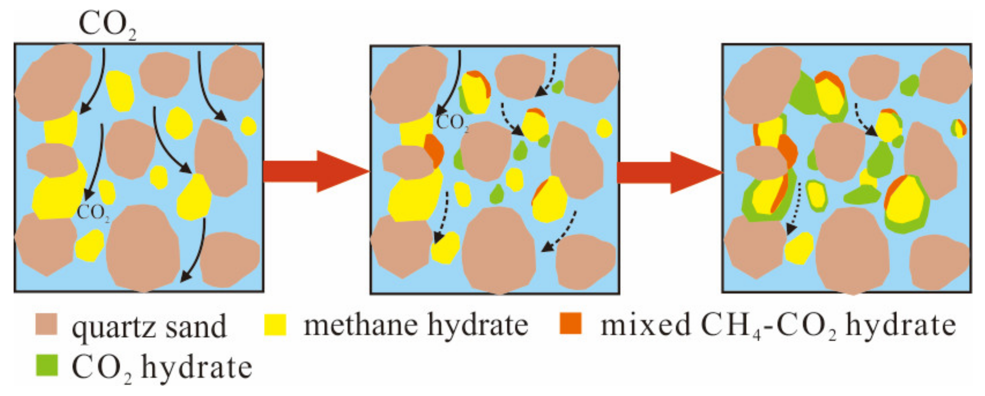
(3)
The CH4/CO2 replacement reaction mainly occurs in the fast reaction stage while the CO2 hydrate formation by CO2 and pore water almost runs through the whole experimental cycle at almost the same rate. Under current experimental conditions and duration, the permeability of the sediments during replacement remained feasible for the diffusion of the gaseous phase. The major hinderance of CH4 recovery should be the diffusion of CO2 through the mix CH4-CO2 layer formed at the surface of methane hydrate.
It is worth noting that, before being applied, the CH4/CO2 replacement process must be carefully evaluated and all the variables which affect the overall efficiency must be considered and analyzed in future investigations.

Author Contributions

Conceptualization, J.S.; Data curation, X.H.; Investigation, Q.C.; Methodology, J.S. and C.L. (Chengfeng Li); Project administration, N.W.; Supervision, N.W., Y.L., L.H. and Q.B.; Validation, C.L. (Changling Liu) and Q.M.; Writing—original draft, J.S.; Writing—review & editing, X.H. All authors have read and agreed to the published version of the manuscript.

Funding

This study is financially supported by the National Natural Science Foundation of China (Grant No. 41976205 & 41906189), and Marine Geological Survey Program (DD20221704).

Data Availability Statement

The data that support the findings of this study are available from the corresponding authors upon reasonable request.

Conflicts of Interest

The authors declare no conflict of interest.

References

  1. Koh, C.A.; Sloan, E.D.; Sum, A.K.; Wu, D.T. Fundamentals and applications of gas hydrates. Annu. Rev. Chem. Biomol. Eng. 2011, 2, 237–257. [Google Scholar] [CrossRef]
  2. Ye, J.; Qin, X.; Xie, W.; Lu, H.; Ma, B.; Qiu, H.; Liang, J.; Lu, J.A.; Kuang, Z.; Lu, C.; et al. Main progress of the second gas hydrate trial production in the South China Sea. Geol. China 2020, 47, 557–568. [Google Scholar]
  3. Dallimore, S.R.; Collett, T.S. Scientific Results from the Mallik 2002 Gas Hydrate Production Research Well Program, Mackenzie Delta, Northwest Territories, Canada; Geological Survey of Canada: Vancouver, BC, Canada, 2005. [Google Scholar]
  4. Dubreuil-Boisclair, C.; Gloaguen, E.; Bellefleur, G.; Marcotte, D. Non-Gaussian gas hydrate grade simulation at the Mallik site, Mackenzie Delta, Canada. Mar. Pet. Geol. 2012, 35, 20–27. [Google Scholar] [CrossRef]
  5. Judith, M.S. From lab to field, from micro to macro—Test of technologies for the production of hydrate bonded CH4 via CO2 sequestration in hydrates. In Proceedings of the 9th International Conference on Gas Hydrates, Denver, CO, USA, 25–30 June 2017. [Google Scholar]
  6. Ebinuma, T. Washington, DC: U.S. Patent and Trademark Office. U.S. Patent No. 5,261,490, 11 May 1993. [Google Scholar]
  7. Geng, C.Y.; Wen, H.; Zhou, H. Molecular simulation of the potential of methane reoccupation during the replacement of methane hydrate by CO2. J. Phys. Chem. A 2009, 113, 5463–5469. [Google Scholar] [CrossRef]
  8. Jadhawar, P.; Yang, J.H.; Chapoy, A.; Tohidi, B. Subsurface carbon dioxide sequestration and storage in methane hydrate reservoirs combined with clean methane energy recovery. Energy Fuel 2021, 35, 1567–1579. [Google Scholar] [CrossRef]
  9. Pan, D.; Zhong, X.; Zhu, Y.; Zhai, L.; Zhang, H.; Li, X.; Wang, Y.; Chen, C. CH4 recovery and CO2 sequestration from hydrate-bearing clayey sediments via CO2/N2 injection. J. Nat. Gas Sci. Eng. 2020, 83, 103503. [Google Scholar] [CrossRef]
  10. Panda, D.; Saini, C.; Singh, S.K.; Kumar, E.A. In situ casting of rice husk ash in metal organic frameworks induces enhanced CO2 capture performance. Sci. Rep. 2020, 10, 20219. [Google Scholar] [CrossRef] [PubMed]
  11. de Kleijne, K.; Hanssen, S.V.; van Dinteren, L.; Huijbregts, M.A.; van Zelm, R.; de Coninck, H. Limits to Paris compatibility of CO2 capture and utilization. One Earth 2022, 5, 168–185. [Google Scholar] [CrossRef]
  12. Ohgaki, K.; Takano, K.; Sangawa, H.; Matsubara, T.; Nakano, S. Methane exploitation by carbon dioxide from gas hydrates-Phase equilibria for CO2-CH4 mixed hydrate system. J. Chem. Eng. Jpn. 1996, 29, 478–483. [Google Scholar] [CrossRef] [Green Version]
  13. Uchida, T.; Ikeda, I.Y.; Takeya, S.; Kamata, Y.; Ohmura, R.; Nagao, J.; Zatsepina, O.Y.; Buffett, B.A. Kinetics and stability of CH4-CO2 mixed gas hydrates during formation and long-term storage. Chem. Phys. Chem. 2005, 6, 646–654. [Google Scholar] [CrossRef]
  14. Smith, D.H.; Seshadri, K.; Wilder, J.W. Assessing the thermodynamic feasibility of the conversion of methane hydrate into carbon dioxide hydrate in porous media. In Proceedings of the First National Conference on Carbon Sequestration, Washington, DC, USA, 14–17 May 2001; pp. 1–16. [Google Scholar]
  15. Yezdimer, E.M.; Cummings, P.T.; Chialvo, A.A. Determination of the Gibbs free energy of gas replacement in SI clathrate hydrates by molecular simulation. J. Phys. Chem. 2002, 106, 7982–7987. [Google Scholar] [CrossRef]
  16. Lee, Y.; Deusner, C.; Kossel, E.; Choi, W.; Seo, Y.; Haeckel, M. Influence of CH4 hydrate exploitation using depressurization and replacement methods on mechanical strength of hydrate-bearing sediment. Appl. Energy 2020, 277, 115569. [Google Scholar] [CrossRef]
  17. Jung, J.; Ryou, J.E.; Al-Raoush, R.I.; Alshibli, K.; Lee, J.Y. Effects of CH4-CO2 replacement in hydrate-bearing sediments on S-wave velocity and electrical resistivity. J. Nat. Gas Sci. Eng. 2020, 82, 103506. [Google Scholar] [CrossRef]
  18. Schoderbek, D.; Farrell, H.; Howard, J.; Raterman, K.; Silpngarmlert, S.; Martin, K.; Smith, B.; Klein, P. ConocoPhillips Gas Hydrate Production Test; ConocoPhillips Co.: Houston, TX, USA, 2013. [Google Scholar]
  19. Kvamme, B. Feasibility of simultaneous CO2 storage and CH4 production from natural gas hydrate using mixtures of CO2 and N2. Can. J. Chem. 2015, 10, 21–30. [Google Scholar] [CrossRef]
  20. Sun, J.Y.; Liu, L.L.; Wang, X.W.; Wang, F.F.; Liu, C.L. Experimental study on the process of CO2 replacement of CH4 from methane hydrate in sediments. Nat. Gas Ind. 2015, 35, 56–62. [Google Scholar]
  21. Ota, M.; Morohashi, K.; Abe, Y.; Watanabe, M.; Smith, R.L., Jr.; Inomata, H. Replacement of CH4 in the hydrate by use of liquid CO2. Energy Convers. Manag. 2005, 46, 1680–1691. [Google Scholar] [CrossRef]
  22. Mok, J.; Choi, W.; Lee, J.; Seo, Y. Effects of pressure and temperature conditions on thermodynamic and kinetic guest exchange behaviors of CH4- CO2 + N2 replacement for energy recovery and greenhouse gas storage. Energy 2022, 239, 122153. [Google Scholar] [CrossRef]
  23. Le, Q.D.; Rodriguez, C.T.; Legoix, L.N.; Pirim, C.; Chazallon, B. Influence of the initial CH4-hydrate system properties on CO2 capture kinetics. Appl. Energy 2020, 280, 115843. [Google Scholar] [CrossRef]
  24. Chen, Y.; Gao, Y.; Zhao, Y.; Chen, L.; Dong, C.; Sun, B. Experimental investigation of different factors influencing the replacement efficiency of CO2 for methane hydrate. Appl. Energy 2018, 228, 309–316. [Google Scholar] [CrossRef]
  25. Li, S.; Zhang, G.; Dai, Z.; Jiang, S.; Sun, Y. Concurrent decomposition and replacement of marine gas hydrate with the injection of CO2-N2. Chem. Eng. J. 2021, 420, 129936. [Google Scholar] [CrossRef]
  26. Zhang, X.; Li, Y.; Yao, Z.; Li, J.; Wu, Q.; Wang, Y. Experimental study on the effect of pressure on the replacement process of CO2-CH4 hydrate below the freezing point. Energy Fuels 2018, 32, 646–650. [Google Scholar] [CrossRef]
  27. Xie, Y.; Zhu, Y.J.; Zheng, T.; Yuan, Q.; Sun, C.Y.; Yang, L.Y.; Chen, G.J. Replacement in CH4-CO2 hydrate below freezing point based on abnormal self-preservation differences of CH4 hydrate. Chem. Eng. J. 2021, 403, 126283. [Google Scholar] [CrossRef]
  28. Zhou, X.; Fan, S.; Liang, D.; Du, J. Replacement of methane from quartz sand-bearing hydrate with carbon dioxide-in-water emulsion. Energy Fuels 2008, 22, 1759–1764. [Google Scholar] [CrossRef]
  29. Yuan, Q.; Wang, X.H.; Dandekar, A.; Sun, C.Y.; Li, Q.P.; Ma, Z.W.; Liu, B.; Chen, G.J. Replacement of methane from hydrates in porous sediments with CO2-in-water emulsions. Ind. Eng. Chem. Res. 2014, 53, 12476–12484. [Google Scholar] [CrossRef]
  30. Ota, M.; Abe, Y.; Watanabe, M.; Smith, R.L.; Inomata, H. Methane recovery from methane hydrate using pressurized CO2. Fluid Phase Equilib. 2005, 228, 553–559. [Google Scholar] [CrossRef]
  31. McGrail, B.P.; Zhu, T.; Hunter, R.B. A new method for enhanced production of gas hydrates with CO2. In Proceedings of the AAPG Hedberg Conference, Vancouver, BC, Canada, 12–16 September 2004. [Google Scholar]
  32. Ota, M.; Saito, T.; Aida, T.; Watanabe, M.; Sato, Y.; Smith, R.L., Jr.; Inomata, H. Macro and Microscopic CH4-CO2 Replacement in CH4 Hydrate Under Pressurized CO2. Environ. Energy Eng. AIChE J. 2007, 53, 2715–2721. [Google Scholar] [CrossRef]
  33. Park, Y.; Kim, D.Y.; Lee, J.W.; Huh, D.G.; Park, K.P.; Lee, J.; Lee, H. Sequestering carbon dioxide into complex structures of naturally occurring gas hydrates. Proc. Natl. Acad. Sci. USA 2006, 103, 12690–12694. [Google Scholar] [CrossRef] [Green Version]
  34. Lee, Y.; Kim, Y.; Lee, J.; Lee, H.; Seo, Y. CH4 recovery and CO2 sequestration using flue gas in natural gas hydrates as revealed by a micro-differential scanning calorimeter. Appl. Energy 2015, 150, 120–127. [Google Scholar] [CrossRef]
  35. Mok, J.; Choi, W.; Seo, Y. The dual-functional roles of N2 gas for the exploitation of natural gas hydrates: An inhibitor for dissociation and an external guest for replacement. Energy 2021, 232, 121054. [Google Scholar] [CrossRef]
  36. Chen, Y.; Gao, Y.; Chen, L.; Wang, X.; Liu, K.; Sun, B. Experimental investigation of the behavior of methane gas hydrates during depressurization-assisted CO2 replacement. J. Nat. Gas Sci. Eng. 2019, 61, 284–292. [Google Scholar] [CrossRef]
  37. Zhang, L.; Yang, L.; Wang, J.; Zhao, J.; Dong, H.; Yang, M.; Liu, Y.; Song, Y. Enhanced CH4 recovery and CO2 storage via thermal stimulation in the CH4/CO2 replacement of methane hydrate. Chem. Eng. J. 2017, 308, 40–49. [Google Scholar] [CrossRef]
  38. Gambelli, A.M.; Rossi, F. Natural gas hydrates: Comparison between two different applications of thermal stimulation for performing CO2 replacement. Energy 2019, 172, 423–434. [Google Scholar] [CrossRef]
  39. Ouyang, Q.; Fan, S.; Wang, Y.; Lang, X.; Wang, S.; Zhang, Y.; Yu, C. Enhanced Methane Production Efficiency with In Situ Intermittent Heating Assisted CO2 Replacement of Hydrates. Energy Fuels 2020, 34, 12476–12485. [Google Scholar] [CrossRef]
  40. Lv, J.; Cheng, Z.; Duan, J.; Wang, S.; Xue, K.; Liu, Y.; Mu, H. Enhanced CH4 recovery from hydrate-bearing sand packs via CO2 replacement assisted thermal stimulation method. J. Nat. Gas Sci. Eng. 2021, 96, 104326. [Google Scholar] [CrossRef]
  41. Gambelli, A.M.; Rossi, F. The use of sodium chloride as strategy for improving CO2/CH4 replacement in natural gas hydrates promoted with depressurization methods. Arab. J. Geosci. 2020, 13, 898. [Google Scholar] [CrossRef]
  42. Pandey, J.S.; Karantonidis, C.; Karcz, A.P.; Solms, N. Enhanced CH4-CO2 Hydrate Swapping in the Presence of Low Dosage Methanol. Energies 2020, 13, 5238. [Google Scholar] [CrossRef]
  43. Lee, B.R.; Koh, C.A.; Sum, A.K. Quantitative measurement and mechanisms for CH4 production from hydrates with the injection of liquid CO2. Phys. Chem. Chem. Phys. 2014, 16, 14922–14927. [Google Scholar] [CrossRef]
  44. Bai, D.; Zhang, X.; Chen, G.; Wang, W. Replacement mechanism of methane hydrate with carbon dioxide from microsecond molecular dynamics simulations. Energy Environ. Sci. 2012, 5, 7033–7041. [Google Scholar] [CrossRef]
  45. Li, C.; Hu, G.; Ye, Y.; Liu, C.; Cheng, J.; Zhang, L.; Zheng, R. Microscopic distribution of gas hydrate in sediment determined by X-ray computerized tomography. J. Optoelectron. Laser 2013, 24, 551–557. [Google Scholar]
  46. Li, C.; Liu, C.; Hu, G.; Sun, J.; Hao, X.; Liu, L.; Meng, Q. Investigation on the multi-parameter of hydrate-bearing sands using nano-focus X-ray computed tomography. J. Geophys. Res. Solid Earth 2019, 124, 2286–2296. [Google Scholar] [CrossRef]
  47. Sloan, E.D.; Koh, C. Clathrate Hydrates of Natural Gases; CRC Press: Boca Raton, FL, USA, 2007. [Google Scholar]
  48. Zhao, J.; Zhang, L.; Chen, X.; Zhang, Y.; Liu, Y.; Song, Y. Combined replacement and depressurization methane hydrate recovery method. Energy Explor. Exploit. 2016, 34, 129–139. [Google Scholar] [CrossRef] [Green Version]
  49. Yuan, Q.; Sun, C.-Y.; Liu, B.; Wang, X.; Ma, Z.-W.; Ma, Q.-L.; Yang, L.-Y.; Chen, G.-J.; Li, Q.-P.; Li, S.; et al. Methane recovery from natural gas hydrates in porous sediment using pressurized liquid CO2. Energy Convers Manag. 2013, 67, 257–264. [Google Scholar] [CrossRef]
Figure 1. Schematic diagram of the experimental apparatus.
Energies 15 05634 g001
Figure 2. Schematic diagram of the sample slices.
Energies 15 05634 g002
Figure 3. X-CT images of hydrate-bearing sediment sample: (a) upper slice, (b) lower slice.
Energies 15 05634 g003
Figure 4. Time evolution of the replacement percentage during CH4/CO2 replacement with different experimental temperatures.
Energies 15 05634 g004
Figure 5. Time evolution of the replacement percentage during CH4/CO2 replacement with different initial hydrate saturations.
Energies 15 05634 g005
Figure 6. The total amounts of recovered methane gas in experiments with different initial hydrate saturation.
Energies 15 05634 g006
Figure 7. Relative contents of CH4 and CO2 in sample slices with different temperatures.
Energies 15 05634 g007
Figure 8. Relative contents of CH4 and CO2 in sample slices with different initial hydrate saturation.
Energies 15 05634 g008
Figure 9. Evolution of pressure during initial hydrate saturation-controlled experiments.
Energies 15 05634 g009
Figure 10. The consumption of CO2 by different processes of Run 2.
Energies 15 05634 g010
Figure 11. Schematic diagrams of the CH4/CO2 replacement process.
Energies 15 05634 g011
Table 1. Experimental conditions of individual CO2 replacement.
Run1Run2Run3Run4Run5Run6Run7Run8
Replacement Temperature (T)1.52.53.55.02.52.52.52.5
Initial hydrate saturation (Sh)46.546.945.846.210.826.742.155.2
Pressure of CO2 injection3.03.03.03.03.03.03.03.0
Publisher’s Note: MDPI stays neutral with regard to jurisdictional claims in published maps and institutional affiliations.

