
Graphene and Resin Coated Proppant with Electrically Conductive Properties for In-Situ Modification of Shale Oil


Abstract
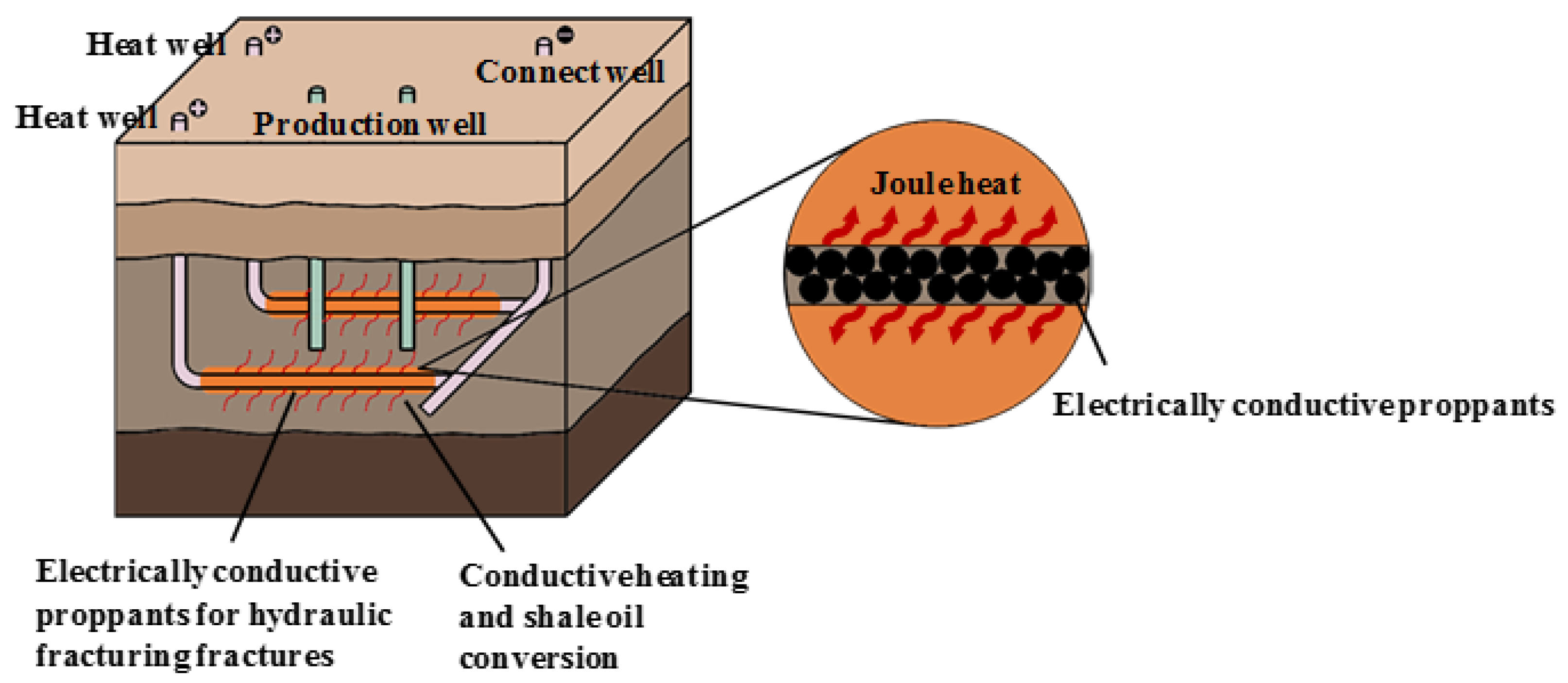
:1. Introduction
2. Materials and Methods
2.1. Experimental Materials
2.2. Preparation of Electrically Conductive Proppant
2.3. Suspension and Sedimentation Experiment
2.4. Electrical Conductivity Experiment
2.5. Characterization
3. Results and Discussion
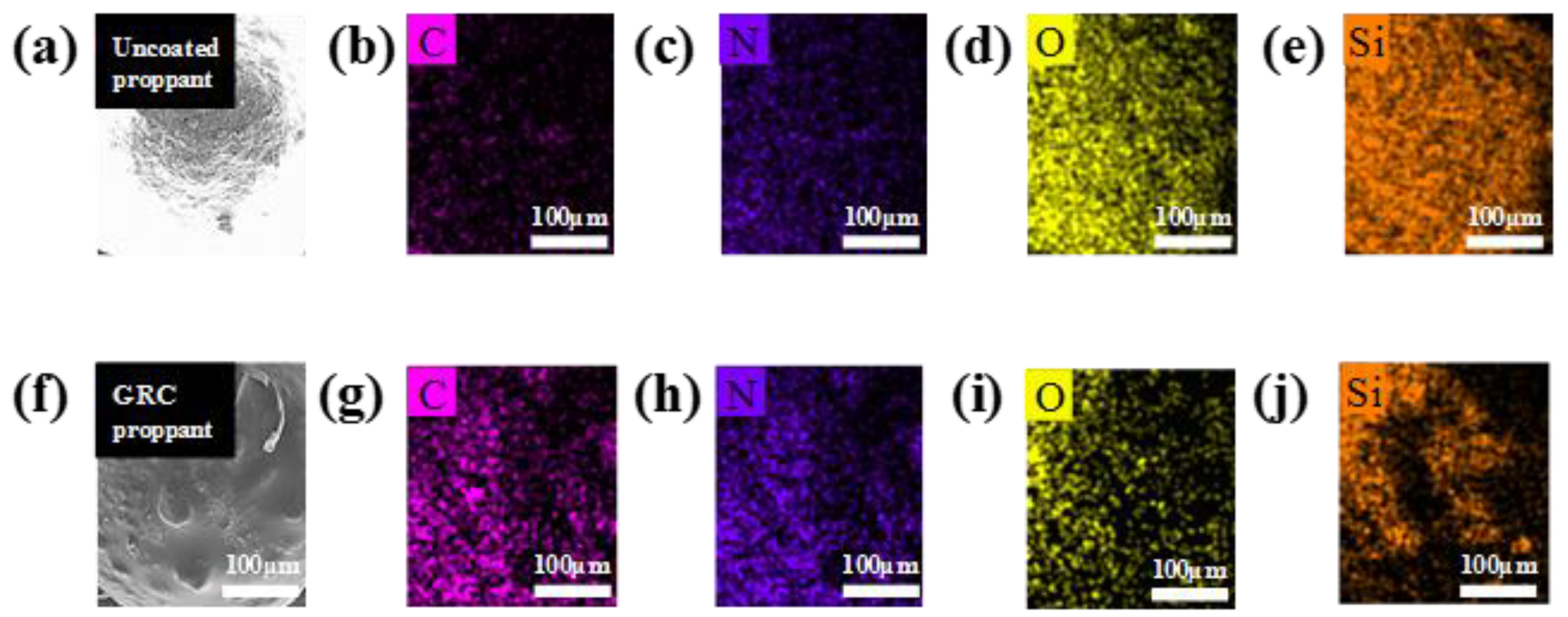
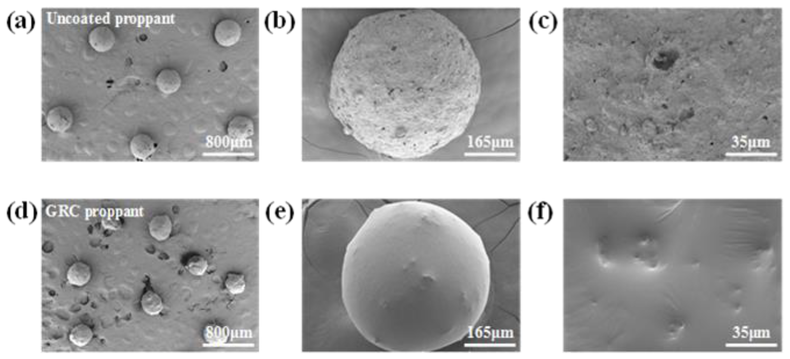
3.1. Morphology Characterization
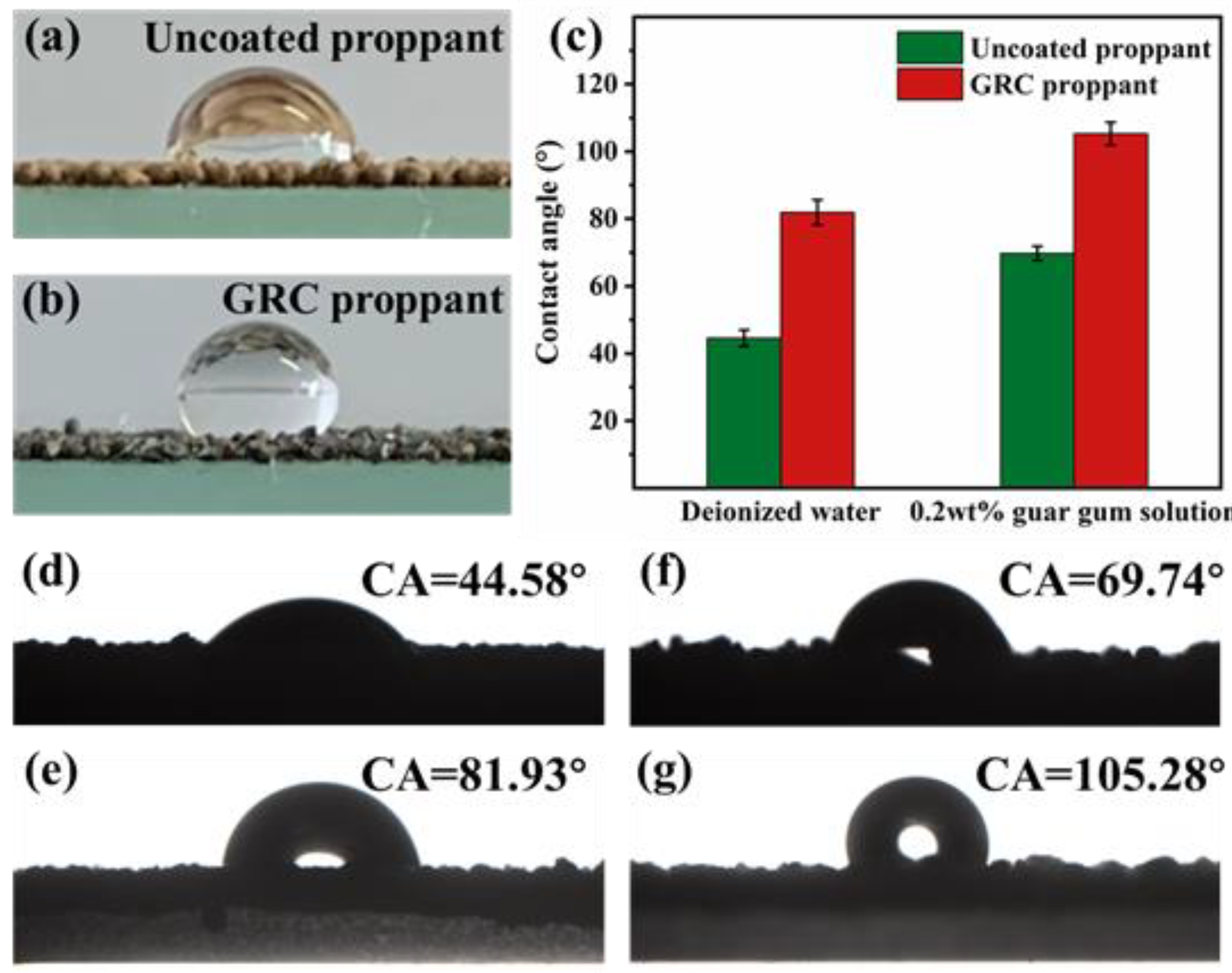
3.2. Hydrophobic Properties
3.3. Suspension and Settlement Properties
3.4. Electrical Conductivity
3.5. Adhesion Properties
3.6. Liquid Conductivity
4. Conclusions
Author Contributions
Funding
Institutional Review Board Statement
Informed Consent Statement
Data Availability Statement
Conflicts of Interest
Abbreviations
| GRC | Graphene and resin coated |
| ICP | In-Situ-Conversion |
| SEM | Scanning electron microscope |
| EDX | Energy-dispersive X-ray spectroscopy |
| AFM | Atomic force microscopy |
| CA | Contact angle |
References
- Zhao, C.; Chen, B. China’s oil security from the supply chain perspective: A review. Appl. Energy 2014, 136, 269–279. [Google Scholar] [CrossRef]
- Dudley, B. BP statistical review of world energy 2014. In Proceedings of the World Petroleum Conference, Moscow, Russia, 16 June 2014. [Google Scholar]
- Kalicki, J.H.; Goldwyn, D.L. Energy and Security: Strategies for a World in Transition; JHU Press: Baltimore, MD, USA, 2013. [Google Scholar]
- Yang, Z.; Zou, C.; Wu, S.; Lin, S.; Pan, S.; Niu, X.; Men, G.; Tang, Z.; Li, G.; Zhao, J.; et al. Formation, distribution and resource potential of the “sweet areas (sections)” of continental shale oil in China. Mar. Petrol. Geol. 2019, 102, 48–60. [Google Scholar]
- Hu, S.; Zhao, W.; Hou, L.; Yang, Z.; Zhu, R.; Wu, S.; Bai, B.; Jin, X. Development potential and technical strategy of continental shale oil in China. Petrol. Explor. Dev. 2020, 47, 877–887. [Google Scholar] [CrossRef]
- Zhao, W.; Hu, S.; Hou, L.; Yang, T.; Li, X.; Guo, B.; Yang, Z. Types and resource potential of continental shale oil in China and its boundary with tight oil. Petrol. Explor. Dev. 2020, 47, 1–11. [Google Scholar] [CrossRef]
- Brandt, A.R. Converting oil shale to liquid fuels: Energy inputs and greenhouse gas emissions of the Shell in situ conversion process. Environ. Sci. Technol. 2008, 42, 7489–7495. [Google Scholar] [CrossRef] [PubMed]
- Speight, J.G. In Situ Retorting. In Shale Oil Production Processes; Gulf Professional Publishing: Houston, TX, USA, 2012; pp. 123–138. [Google Scholar]
- Lee, S.; Speight, J.G.; Loyalka, S.K. Handbook of Alternative Fuel Technologies; CRC Press: Boca Raton, FL, USA, 2014. [Google Scholar]
- Liu, D.X.; Wang, H.Y.; Zheng, D.W.; Fang, C.H.; Ge, Z.X. World progress of oil shale in-situ exploitation methods. Nat. Gas Ind. 2009, 29, 128–132. [Google Scholar]
- Jaber, J.O.; Probert, S.D. Environmental-impact assessment for the proposed oil-shale integrated tri-generation plant. Appl. Energy 1999, 62, 169–209. [Google Scholar] [CrossRef]
- Han, X.X.; Jiang, X.M.; Cui, Z.G. Studies of the effect of retorting factors on the yield of shale oil for a new comprehensive utilization technology of oil shale. Appl. Energy 2009, 86, 2381–2385. [Google Scholar] [CrossRef]
- Gavrilova, O.; Vilu, R.; Vallner, L. A life cycle environmental impact assessment of oil shale produced and consumed in Estonia. Resour. Conserv. Recy. 2010, 55, 232–245. [Google Scholar] [CrossRef]
- Niu, M.; Wang, S.; Han, X.; Jiang, X. Yield and characteristics of shale oil from the retorting of oil shale and fine oil-shale ash mixtures. Appl. Energ. 2013, 111, 234–239. [Google Scholar] [CrossRef]
- Neshumayev, D.; Pihu, T.; Siirde, A.; Järvik, O.; Konist, A. Solid heat carrier oil shale retorting technology with integrated CFB technology. Oil Shale 2019, 36, 99. [Google Scholar] [CrossRef]
- Arro, H.; Prikk, A.; Pihu, T. Calculation of qualitative and quantitative composition of Estonian oil shale and its combustion products. Part 1. Calculation on the basis of heating value. Fuel 2003, 82, 2179–2195. [Google Scholar] [CrossRef]
- Boak, J. Oil Shale: Is Now the Time? Energy Advisory Board: Garfield County, CO, USA, 2011. [Google Scholar]
- Allix, P.; Burnham, A.; Fowler, T.; Herron, M.; Kleinberg, R.; Symington, B. Coaxing oil from shale. Oilfield Rev. 2010, 22, 4–15. [Google Scholar]
- Kang, Z.; Zhao, Y.; Yang, D. Review of oil shale in-situ conversion technology. Appl. Energy 2020, 269, 115121. [Google Scholar] [CrossRef]
- United States. Congress. Office of Technology Assessment. In An Assessment of Oil Shale Technologies; Congress, Office of Technology Assessment: Washington, DC, USA, 16 July 1980. [Google Scholar]
- Burnham, A.K.; McConaghy, J.R. Comparison of the acceptability of various oil shale processes. In Proceedings of the 26th Oil Shale Symposium, Golden, CO, USA, 16–18 October 2006. [Google Scholar]
- Prats, M.; Closmann, P.J.; Ireson, A.T.; Drinkard, G. Soluble-salt processes for in-situ recovery of hydrocarbons from oil shale. J. Petrol. Technol. 1977, 29, 1078–1088. [Google Scholar] [CrossRef]
- Dammer, A.R.K.; James, C.; Biglarbigi, K.; Crawford, P.M.; Johnson, H. Secure Fuels from Domestic Resources: The Continuing Evolution of America’s Oil Shale and Tar Sands Industries; Department of Energy, Office of Naval Petroleum and Oil Shale Reserves: Washington, DC, USA, 2007. [Google Scholar]
- Council, W.E. Survey of Energy Resources; World Energy Council: London, UK, 2010. [Google Scholar]
- Vinegar, H. Shell’s in-situ conversion process. In Proceedings of the 26th Oil Shale Symposium, Golden, CO, USA, 16–18 October 2006. [Google Scholar]
- Li, Y.H.; Zhang, H.; Zhang, J.H. The present situation and progress of oil shale exploration and exploitation. CT Theory Appl. 2014, 23, 1051–1063. [Google Scholar]
- Huang, Z.; Yuan, W.; Huang, W.; Paul, E. Current mining technology of oilshale. Resour. Ind. 2009, 10, 22. [Google Scholar]
- Crawford, P.; Biglarbigi, K.; Dammer, A.; Knaus, E. Advances in world oil-shale production technologies. In Proceedings of the SPE Annual Technical Conference and Exhibition, Denver, CO, USA, 21–24 September 2008. [Google Scholar]
- Khaled, M.S. Oil Shale Technology and Efficient Utilization of Oil Shale Resources in Egypt. In Proceedings of the SPE Annual Technical Conference and Exhibition, San Antonio, TX, USA, 8–10 October 2012. [Google Scholar]
- Kaminsky, R.D.; Symington, W.A. Hydrocarbon Recovery from Impermeable Oil Shales. U.S. Patent 7,441,603, 28 October 2008. [Google Scholar]
- Crawford, P.M.; Killen, J.C. New challenges and directions in oil shale development technologies. Oil Shale A Solut. Liq. Fuel Dilemma 2010, 21–60. [Google Scholar] [CrossRef]
- Biglarbigi, K.; Dammer, A.; Mohan, H.; Carolus, M.J. Economics of Oil Shale Development in the United States. In Proceedings of the SPE Annual Technical Conference and Exhibition, Denver, CO, USA, 21–24 September 2008. [Google Scholar]
- Tanaka, P.L.; Yeakel, J.D.; Symington, W.A.; Spiecker, P.M.; Del Pico, M.; Thomas, M.M.; Sullivan, K.B.; Stone, M.T. Plan to test ExxonMobil’s in situ oil shale technology on a proposed RD&D lease. In Proceedings of the 31st Oil Shale Symposium, Golden, CO, USA, 17–19 October 2011. [Google Scholar]
- Ahmmed, B.; Mudunuru, M.K.; Karra, S.; James, S.C.; Viswanathan, H.; Dunbar, J.A. PFLOTRAN-SIP: A PFLOTRAN Module for Simulating Spectral-Induced Polarization of Electrical Impedance Data. Energies 2020, 13, 6552. [Google Scholar] [CrossRef]
- Karra, S.; Viswanathan, H.S.; Mudunuru, M.K.; Chillara, V.K.; Sinha, D.N. Triad National Security LLC. Multi-Frequency Electrical Impedance Tomography. U.S. Patent 11,293,279, 5 April 2022. [Google Scholar]
- Mahoney, R.P.; Soane, D.; Kincaid, K.P.; Herring, M.; Snider, P.M. Self-suspending proppant. In Proceedings of the SPE Hydraulic Fracturing Technology Conference, The Woodlands, TX, USA, 4–6 February 2013. [Google Scholar]
- Mahoney, R.P.; Soane, D.S.; Hering, M.K.; Kincaid, K.K.; Portilla, R.C.; Wuthridge, P. Self-Suspending Proppants for Hydraulic Fracturing. U.S. Patent Application 13/923,158, 2 January 2014. [Google Scholar]
- Radwan, A. A multifunctional coated proppant: A review of over 30 field trials in low permeability formations. In Proceedings of the SPE Annual Technical Conference and Exhibition, San Antonio, TX, USA, 9–11 October 2017. [Google Scholar]
- Gadekea, L.L.; Smith, H.D. Trancerscan: A Spectroscopy Technique For Determining The Distribution Of Multiplte Radioactive Tracers In Downhole Operations. Log Anal. 1987, 28, SPWLA-1987-v28n1a3. [Google Scholar]
- Taylor III, J.L.; Brandy, T.R. Tracer technology finds expanding applications. Pet. Eng. Int. 1989, 61, 6958524. [Google Scholar]
- Irie, S.; Rappolt, J. Phenolic resin for refractories. In Phenolic Resins: A Century of Progress; Springer: Berlin/Heidelberg, Germany, 2010; pp. 503–515. [Google Scholar]


Publisher’s Note: MDPI stays neutral with regard to jurisdictional claims in published maps and institutional affiliations. |
© 2022 by the authors. Licensee MDPI, Basel, Switzerland. This article is an open access article distributed under the terms and conditions of the Creative Commons Attribution (CC BY) license (https://creativecommons.org/licenses/by/4.0/).
Share and Cite
Chen, S.; Liu, F.; Zhou, Y.; Lan, X.; Li, S.; Wang, L.; Xu, Q.; Li, Y.; Jin, Y. Graphene and Resin Coated Proppant with Electrically Conductive Properties for In-Situ Modification of Shale Oil. Energies 2022, 15, 5599. https://doi.org/10.3390/en15155599
Chen S, Liu F, Zhou Y, Lan X, Li S, Wang L, Xu Q, Li Y, Jin Y. Graphene and Resin Coated Proppant with Electrically Conductive Properties for In-Situ Modification of Shale Oil. Energies. 2022; 15(15):5599. https://doi.org/10.3390/en15155599
Chicago/Turabian StyleChen, Siyuan, Fanghui Liu, Yang Zhou, Xiuping Lan, Shouzhen Li, Lulu Wang, Quan Xu, Yeqing Li, and Yan Jin. 2022. "Graphene and Resin Coated Proppant with Electrically Conductive Properties for In-Situ Modification of Shale Oil" Energies 15, no. 15: 5599. https://doi.org/10.3390/en15155599
APA StyleChen, S., Liu, F., Zhou, Y., Lan, X., Li, S., Wang, L., Xu, Q., Li, Y., & Jin, Y. (2022). Graphene and Resin Coated Proppant with Electrically Conductive Properties for In-Situ Modification of Shale Oil. Energies, 15(15), 5599. https://doi.org/10.3390/en15155599