1. Introduction
Mineral oil (MO) has been one of the most frequently used insulation liquids in power transformers. The long-term use of MO in electrical power equipment has improved its production and treatment, leading to an affordable price [
1]. Despite mineral oil’s positive characteristics and acceptance over the years, its flammable downside is well known. [
2,
3]. It is an explosive fluid; if a transformer leaks mineral oil, it can potentially start a fire. On the other hand, when there is a large fire in an MO transformer, an occurrence which often takes place, great damage can be brought forth along with expensive cleaning of the surrounding area if the tank has ruptured severely [
4]. Some other drawbacks can be attributed to mineral oil, as it is an environmental contaminant if it is spilled and small amounts of water rapidly degrade its insulating properties [
5].
The answer to these problems lies in using alternative fluids in power transformers, those which are less flammable and much more environmentally friendly. Thus, a new generation of insulating liquids has emerged—the ester oils, conveying a possible alternative to the MO that is generally used in power transformers [
6].
In the last decades, ester liquids have gained acceptance for their use in transformer insulation and cooling, providing fire-safe and environmentally friendly alternatives to traditional mineral oil. That shift has been attributed to growing environmental awareness and the advancement of new options in liquid dielectrics resulting from sustainable, renewable, and non-polluting natural resources [
7,
8,
9].
Ester liquids look like a natural and safe solution; they have associated advantages, such as a lower substation footprint and oil contamination design [
10]. Ester oils are composites from organic alcohols and acids; they are accessible as natural goods or chemically synthesized from organic precursors [
11,
12]. Notwithstanding that the electrical power transformer industry has been interested in ester oil as an alternative to mineral oil, it is still necessary to show good dielectric performance and electric safety [
13].
A transformer’s life expectancy depends on its insulation material and electric stress conditions. Overvoltage that is generated by lightning surges spreads an irregular voltage distribution across the insulation, possibly leading to the insulation system’s breakdown [
14]. Specifying the transformer’s winding insulation requires knowledge of the electrical stresses that the winding can face during quick transient oscillations, the voltage arising along the insulation, and the insulation’s strength against a lightning impulse voltage. [
15]. Providing pertinent voltage distribution and impulse response information in the design phase will permit the designer to select the best insulating fluid to fit the standards, rules, and consumers’ choices.
This work aims to analyze and compare the behaviors of core type power transformers that were immersed in mineral oil and ester oil. Three case studies that were carried out in a local transformer manufacturer’s facility are described, corresponding to three different classes of transformers; namely those with power ratings of 20 MVA, 50 MVA, and 125/40 MVA. Furthermore, a method for calculating the transformers is described in
Section 4. It consists of a sequence of processes, from the sizing of the active part and insulating structures of the transformer to the calculation of the dielectric stresses and electric field analysis. The results were obtained from the use of specific software with the automatic correction of errors and deviations so as to ensure compliance with the legislation relating to this equipment.
2. Transformer Insulating Fluids
It is normally accepted that an insulating liquid must satisfy several operational conditions, such as the appropriate dielectric and thermal properties, low flammability, low viscosity, compatibility with further transformer materials, miscibility with other fluids, environmental adequacy, and, last but not least, low cost. [
13,
16,
17]. This section compares the dielectric liquids that can be employed as coolants in oil-filled transformers: mineral and ester oils.
2.1. Mineral and Ester Oil
Mineral oil is a fossil fuel resulting from crude oil. The crude petroleum distillation process generates hydrocarbons, of which a part is refined, delivering a compound with different bonds [
10,
18]. The boiling range of the collected fraction and the type and degree of the refining process are selected such that the resulting oil reaches the requirements that are specified for its use in transformers. Several mineral oil types can be used in power transformers, such as paraffinic, naphthenic, and aromatic. All of them contain different ratios of components [
19]. Usually, mineral oils combine compounds that are prepared so as to deliver the expected viscosity–temperature relationship [
20].
Natural and synthetic ester fluids are options that may be used to replace mineral oils. We can find natural, synthetic, and blended esters among the ester liquids, which have been known to have operated in proper conditions for many years [
21,
22]. However, those product types differ to a small extent, mainly concerning their sources (i.e., from soy, sunflower, rapeseed, and others) [
23,
24].
Thanks to synthetic esters’ environmental properties (high fire point and biodegradability), research on synthetic ester liquids has recently intensified [
25]. Low power and voltage distribution transformers have often employed ester fluids, but there has been a steady trend in increasing their rated power and nominal voltage. Presently, transformers that use synthetic esters reach a nominal voltage of 400 kV [
6].
2.2. Ester Versus MO Properties
Both ester and mineral oil dielectric fluids are expected to offer suitable physical and chemical properties for the electrical isolation of power transformers, which effectively fulfills their technical, electrical, and economic goals. However, their different characteristics create both pros and cons [
26].
Ester fluids have some positive advantages when compared to MO. In addition to their inherent biodegradable characteristic, they have a higher flashpoint, which describes “the lowest temperature at which the vapor above the oil sample will momentarily ignite or flash when an ignition source is passed over it” [
27]. Another advantage of using an ester is that it can absorb a larger amount of water than MO, permitting the dielectric paper of the transformer to run dryer [
28,
29], producing a resulting favorable effect on the life expectancy of the transformer.
However, ester fluids have properties that put them at a disadvantage when compared to mineral oil. The MOs normally have a lower viscosity than esters. This decreases the flow rate of the fluid for a specific dynamic head, inducing a greater difference in the temperature between the top and bottom of the power transformer’s cooling device [
26]. Hence, their flow through the transformer’s cooling channels is slower, whereas the ester transformer’s temperatures are higher. As a result, ester-filled transformers run between 1 and 3 °C hotter than similar MO-based units [
30,
31]. The higher viscosity of the ester fluids partially compensates for the more advantageous thermal conductivity [
26]. In addition, the esters’ oxidation rate is more elevated, particularly that of natural esters (NE), which renders them more adequate for use in sealed units. Finally, NE have an elevated pour point, meaning they are not perfect for outdoor transformers in chilly zones unless specific safeguards are considered.
2.3. Dielectric Design
Although multiple investigations on the dielectric and thermal properties of ester fluids have been disclosed, their estimation is still a current research topic. The primary roles of dielectric fluids, whether they be ester oils or MOs, are to secure the electrical insulation of a transformer; a role which complex solid–liquid insulation structures can control [
32]. Furthermore, the oil fluids impregnate the dielectric paper, the so-called kraft paper, this is an electrical grade paper that is one of the cheapest and best insulation materials that are used inside the transformer’s windings (
Figure 1) [
33]. Therefore, the dielectric paper should have high dielectric strength and be free from conducting particles. In addition, it is necessary to take special care to impregnate the solid insulators of the transformer with dielectric fluids in the course of their manufacturing process, which can condition their life expectancy [
34]. An incorrect impregnation procedure may lead to air voids, decreasing the dielectric papers’ insulating capacity and enabling potentially disastrous failures [
35].
Ester oils’ relative permittivity is usually higher than that of MOs and it is more comparable to that of the typically used kraft paper [
26,
29]. The fluid is the frail material in the transformer’s insulation structure. If the liquid permittivity and the solid insulation become closer, the dielectric stress will be more distributed across the solid material [
36]. Thus, the voltage stress in the fluid is reduced when changing from MO to ester. Usually, higher voltage stress in the paper is preferable, as this material is thought to be the stronger of the two dielectrics. The stress between the paper and fluid is lower in the case of the ester, suggesting a more even distribution [
4].
In power transformers, the permittivity variations introduce differences in the electric fields’ distribution across the oil–paper insulation [
31]. Some works have compared synthetic esters and mineral oil regarding the distribution of the electrical field in the winding structures of power transformers [
37,
38].
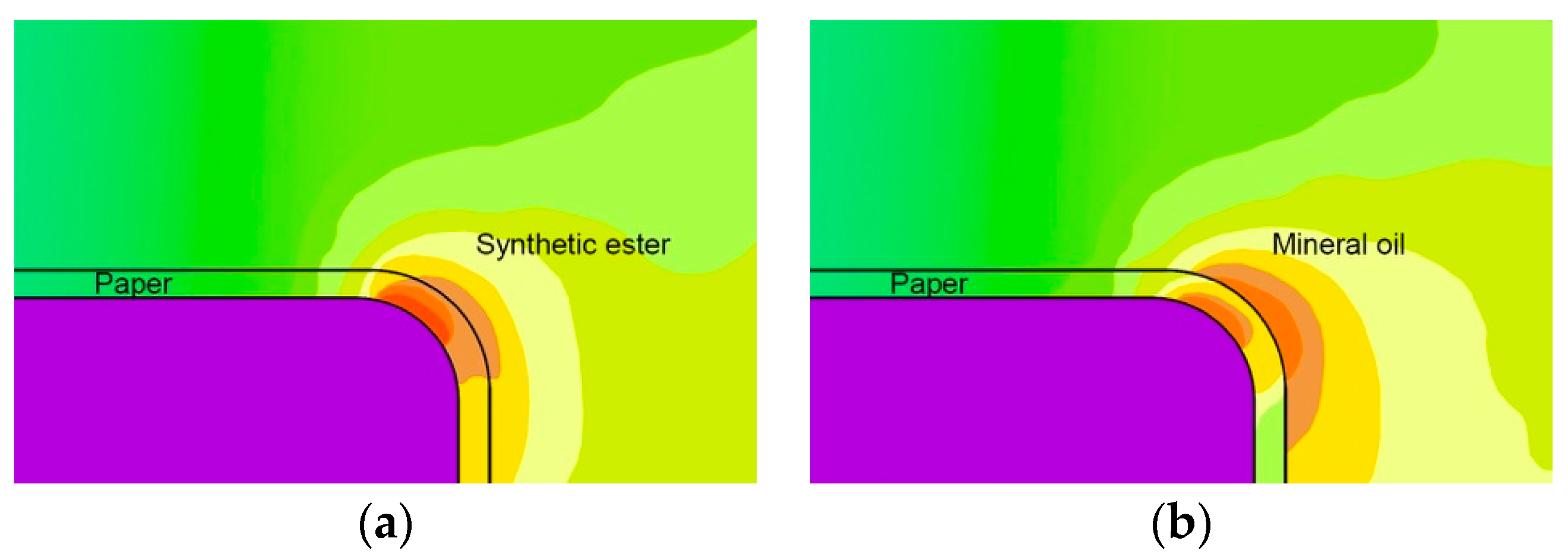
Figure 2 shows the magnified fragment of the distribution of an electric field on a central insulation part that had been isolated with MO and synthetic esters.
Figure 2 shows that the electrical field’s intensity is higher in the paper when the dielectric liquid is a synthetic ester, as is reflected in the region in dark red. Nonetheless, the electric field’s stress in the liquid insulation is lower in the case of the synthetic ester (light orange color in
Figure 2a) than in that of MO (dark orange color in
Figure 2b). Such results are not surprising since the higher electrical permittivity of synthetic esters, as opposed to MO, diminishes the electrical field in this medium, in contrast to the growth of the stress of the electrical field that occurs with the use of solid insulation [
38,
39,
40]. On the one hand, for ester-based equipment, that result could be valuable because the field distribution will then be more homogeneous; therefore, it would soften the stress that is resisted by the dielectric fluid. However, on the other hand, the similarity of the esters’ permittivity and that of the solid insulation might raise the likelihood of creep breakdown [
38].
2.4. Thermal Design
A good thermal design is essential in power transformer design as it is directly associated with the insulation systems’ aging rate and, therefore, their life expectancy [
41]. The oil’s aging is essential for the transformer’s life span as the oil’s characteristics determine the paper’s deterioration. Esters can bear more water than mineral oil can and this can extend the paper’s life. The natural ester has experimentally been shown to extend the life of the paper or allow a transformer to run at a higher temperature [
25].
The more elevated viscosity of esters is a primary consideration when considering a thermal design. The fluid’s viscosity is vital in determining the fluid’s cooling capability, as it characterizes the resistance to the flow. Thus, a high level of viscosity may delay the fluid’s flow in the winding cooling ducts and raise the transformer’s operating temperature—a fact to regard in the power transformers’ thermal design [
42]. High viscosity lowers the capacity to transfer heat from the active transformer’s components to the external environment and raises the temperature in hot spots. Thus, machines with this sort of fluid should run at high loads in order to diminish their viscosity and enhance the refrigeration circuit’s performance [
43].
Another topic that has provoked special interest is modeling esters’ thermal properties at low temperatures. Under those circumstances, the viscosity has a more powerful impact than the other properties. Knowing the esters’ behavior at low temperatures is paramount because, below their pour point (i.e., the lowest temperature at which an oil fluid could flow), esters start to gel. In addition, in the transformer manufacturing process, high viscosity must be taken into consideration throughout the liquid impregnation of the cellulose solid; the more viscous a fluid is, the slower the flow speed will be inside the capillaries. Therefore, the effectiveness of ester oils’ impregnation of cellulose insulation can be accomplished within a period that is comparable to that of MO by means of raising the impregnation temperature [
35,
44].
3. Transformer Dielectric Tests
During power operation, transformers are subject to high-voltage and high-frequency stresses. Therefore, it is necessary to carry out various dielectric tests, such as tests of the short-time/long-time power frequency, lightning impulse (LI), and switching impulse. In addition, these tests must comply with standardized tests and fulfill precise conditions before running in the power system. The international standard IEC 60076-3 [
45] defines the dielectric tests that are to be performed on the transformer, as well as the voltages that are to be applied and their durations. Other standards can be found in [
29].
One of the most important tests to consider is the LI test, which analyzes the transformers’ capacity to hold transient overvoltage. Because of the disastrous impact that transient overvoltage can have on transformers—for example, an insulation breakdown—it is helpful and critical to have a precise simulation of the LI test available alongside the transformer design process [
46,
47]. This test is carried out with negative polarity standard lightning impulses.
The front time (T
1) and the time to half-value (T
2) are established according to the international standard lightning impulse: front time T
1 = 1.2 μs ± 30% and the time to half-value T
2 = 50 μs ± 20% (
Figure 3).
The impulse is carried out for a three-phase transformer; the voltage is applied on each line terminal, maintaining the earthing of the other terminals. An oscilloscope registers the wave shapes of the current and voltage; any distortion is considered a failure.
Transformers can utilize different operational regimes by regulating the voltage of the high voltage winding. The client defines the voltage variation, allowing it to reach a maximum or minimum value, depending on the tap winding (regulator) buck position. The nominal, maximum, and minimum attained values are known as the nominal, maximum, and minimum tap. In addition, the nominal tap can have two positions—the concordant and discordant nominal tap, which are chosen according to the dielectric demands. If the applied voltage decreases from the maximum position to a nominal position, the concordant nominal tap is used. The discordant nominal tap is used from a minimum to a nominal position. The only difference between the two schemes is the test connection diagram, as depicted in
Figure 4.
In
Figure 4, the high voltage winding (the upper rectangle in each image) has two terminals; the upper one is labeled as “1” and the lower one as “3”. The bottom winding is the tap regulator, with its terminals labeled as “4” for the upper one and “n” for the lower one; being “n” the upper terminal plus the number of steps in the voltage range.
In the left picture (a), the induced voltage wave applies a high voltage across terminal 1. The current flows to terminal 3, which is connected to terminal 4, and the current then flows through the tap winding until it reaches selector 2, which is connected to the ground. In the case of the nominal tap concordant (b), impulse lightning is also applied to terminal 1. However, terminals 3 and 4 are interconnected in this situation and selector terminal 2 is connected to 4, which means that it will not add nor subtract spirals, thus maintaining the nominal position. In nominal tap discordant (c), the process is similar; still, terminal 3 is connected to n and the selector terminal 2 is connected to terminal n. Performing dielectric tests in a manufacturer’s facilities is essential to keeping their production running safely and efficiently.
It is worth reporting a recent study by Carvalhosa et al. [
7] wherein several experiments with ester solutions in higher voltage transformers were performed, using virtual design (simulation techniques and software) and carrying out different physical dielectric tests in a laboratory environment. Their approach was similar to that of the present research in that the modeling parameters were based on clients’ requirements and the simulation was conducted so as to comply with current appliable standards and regulations.
The current industry body of knowledge could be seen as being excessively restrictive concerning knowledge of the insulation capacity of ester dielectric fluids, which creates a bias towards oversized transformers or lower-rated power capacity transformers. According to Carvalhosa et al. [
7], new design methodologies and testing could provide a way to overcome such limitations.
4. Transformer Calculation Method
This section describes the method that was used for calculating a core type transformer, covering the functional design inside the tank. A local transformer manufacturer has validated all of the design and calculation results for the three case studies that are analyzed in this work.
Three models were carried out so as to simulate power transformers with power ratings of 20 MVA, 50 MVA, and 125/40 MVA. The dielectric characteristics of an ester oil-based transformer were calculated and the results were compared to those of a transformer using mineral oil. Important dielectric issues were analyzed, such as the window design sizing, dielectric stresses, and electric field.
4.1. Winding Arrangment
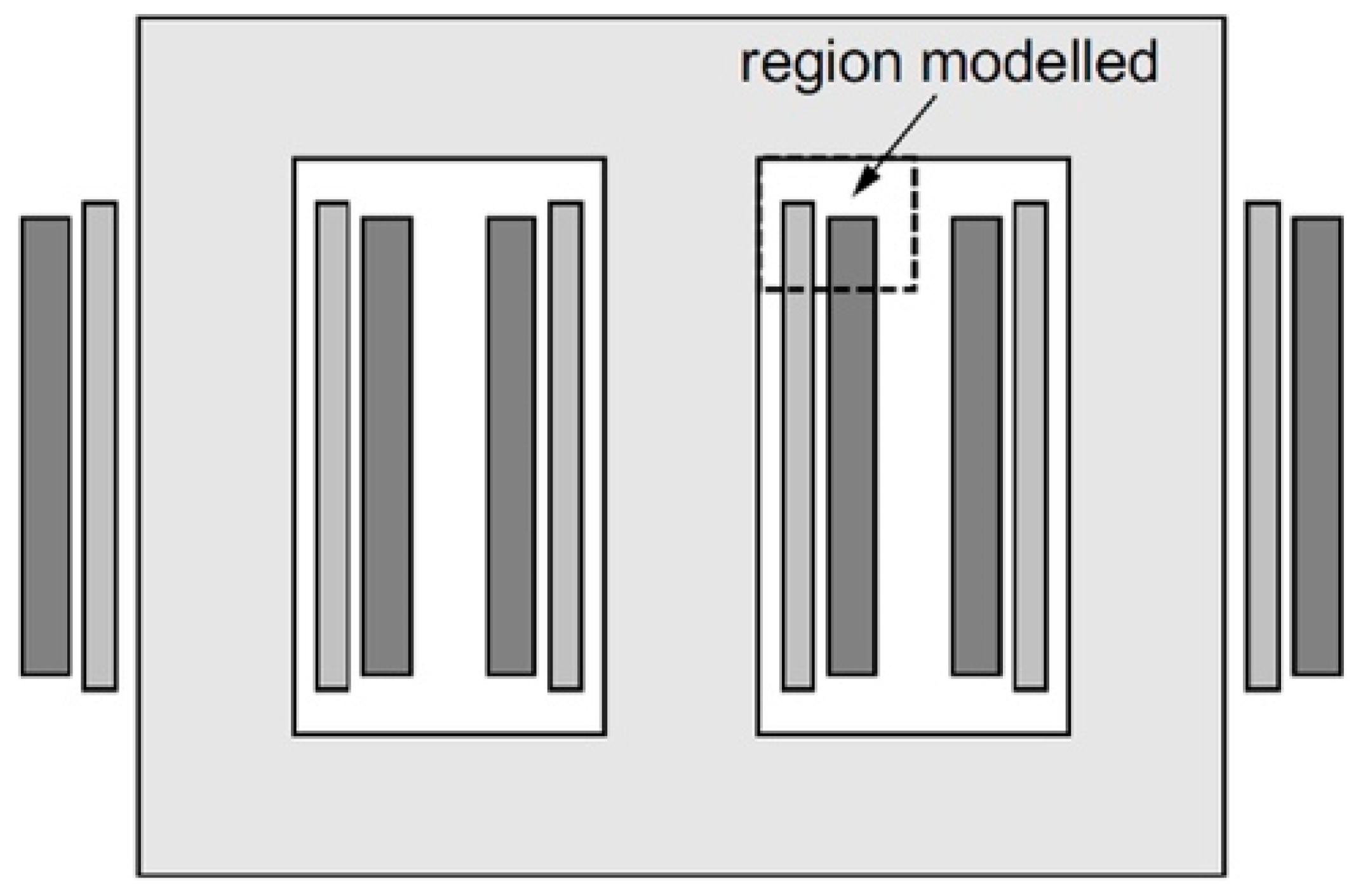
In core-type transformers, the windings are positioned on the circular core limbs, circumventing them, with a shared flux path in the laminated core (
Figure 5) [
48]. In this type of design, the low voltage section is closest to the core so as to optimize material use. Since the low voltage section carries more current than the high voltage one, it uses more material [
49]. Therefore, this section reduces the average winding length and the amount of material that is needed.
For the design of the windings, the core window height and width dimensions dictate the dimensions and winding’s design. The winding dimension must also take into account the dielectric clearances as well as the need for cooling ducts.
The design of the insulation structure is mainly based on a known electric field distribution inside the transformer. For the calculation of the electric field, we have used the 2D model for analyzing the outlined region that is shown in
Figure 5, which is limited to the upper part of the LV and HV windings. The region that is modeled determines the calculation of the whole transformer; all of the simulations that are described henceforth refer to this region.
4.2. Calculation Process
The transformer calculation needs to comply with the customer’s specifications and standards. The clients’ requirements not only concern voltage and power features, but they are also concerned with maximum size, loss values, short circuit impedances, insulation levels, and heating and cooling regimes. All of this data matters to the transformer calculation process, impacting on winding distances, winding materials, and manufacturing sizing.
The flow chart of the core transformer calculation process involves three main steps: the region modeled design (as seen in
Figure 5), dielectric stresses check, and electric field analysis. Those calculation steps involve using specific software; CORET, CoreTransient (proprietary software), and Electro™ (
Figure 6), respectively.
The transformer calculation began by defining the region modeled design, this is a process which consists of scaling the active part (the windings and the magnetic circuit) and its insulation structure (paper thickness and pressboard). This calculation stage relies on the CORET software, which deals with the transformer’s electrical, thermal, and magnetic dimensions. The main inputs for this software are the magnetic circuit’s diameter, winding voltages (low and high voltage, tertiary, regulation), duct distances, conductor types, and cooling type; the outputs are the short circuit voltage, peak and off-peak losses, heating, and mechanical stresses. In addition, the software automatically checks the input values, reporting errors and missing values; it also post-processes the results so as to prepare the input data for the next stage of the calculation flow chart. As a result, CORET provides the electric circuit quantities, as well as the mutual coupling factors, which will be the inputs for the software in the following step.
The CoreTransient software calculates the lightning impulse test values (the concept that was described in
Section 3). Firstly, the basic impulse voltage (BIL) was applied and then the dielectric strength was analyzed by simulating each operating tap and its electrical connections. The BIL is the maximum impulse voltage that the electrical equipment can withstand without damage. The dielectric strength results that were rendered are the potential values in the different winding sections (cells). Once known, those values need to be validated against the relevant standards and, in the end, the ability of the respective insulations to withstand such dielectric stresses must be verified.
This analysis was performed in 2D through the use of different sections representing the geometry of the windings, as seen in
Figure 7. This figure shows a simulation that was performed for the transformer’s operation in maximum tap (as illustrated in
Figure 4) and it is an example of a wiring diagram that was generated by the CoreTransient software. The lower voltage winding is the leftmost winding, the high voltage winding is the middle winding, and the tap winding (regulation) is the rightmost winding. The windings are divided into cells that are numbered sequentially and each cell has six nodes with which to make connections.
The CoreTransient outputs are the dielectric stresses results, which are a piece of essential information that are needed to validate the ability of materials and insulations to support the stress. That is why it is essential to properly calculate the insulation system during the transformer’s design stage.
It is crucial to consider that the electric field should not exceed the specified critical value during the dimensioning process. Field analysis may require complex analytical or numerical methods for the electric field computation during the design phase [
50,
51]. In this work we used Electro™ (version 11.0) software to analyze a two-dimension model of different representative sections of the transformer’s windings.
4.3. Insulation Fluid System
The design of a transformer’s insulation system is carried out through the analysis of the electric field distribution on winding-to-winding, winding(s) to the core, the insulation fluid gap, and the winding’s wedges. Firstly, the stresses that were obtained from transient voltage analysis were converted to their equivalent AC voltages, which were then applied to the geometry of the insulation system under study. This resulted in obtaining the electric stress reference maximum values that were established by the individual manufacturers. At this point, those reference values can be analyzed against the safety factor, which is the ratio between the withstand voltage (permissible lightning impulse) and the applied voltage. That safety factor ratio is determined by the manufacturer’s propriety software and provides a non-dimensional value that quickly shows the extent to which the region that has been modeled is “safe”; that is, the proportion to which the voltage that can be withstood covers the applied voltage.
Figure 8 is an example of the stress simulation that was performed in this work, showing the safety factors that were calculated across the insulation fluid gaps in the insulation system design. The safety factor peaked at specific winding locations depending on the physical configuration and waveform parameters. Usually, the electric stresses across the line end coils and fluid wedges are more significant than those between winding section spots.
In this work, the electric field was analyzed at the winding terminals (where the electric field lines tend to concentrate), between windings, through the ducts, and at the insulation fluid wedges. The applied method in the present research follows the local manufacturer’s references and accordingly assumes, in the area between windings/ducts, that the safety factor must be equal to or greater than 1.2 for mineral oil and 1.32 for ester oil. The maximum permissible electric field value in the oil in the wedge area is 12 kV/mm for the mineral oil and 10.9 kV/mm for ester oil [
52]. Results are presented for both the mineral oil and ester fluids.
5. Results
In this work, we developed an intensive workflow for analyzing and comparing the behaviors of core type power transformers that are immersed in mineral oil and ester oil. The study was implemented in three different classes of transformers, namely, those with rated powers of 20 MVA, 50 MVA, and 125/40 MVA. The results of the applied method are presented, showing the necessary physical dimensions that are required to guarantee the electric field strength that is needed to comply with the specifications that are indicated in
Section 4.3 for the maximum reference values.
Table 1 shows, for each of the three case studies, the general description of the transformers and the voltage application values for which they must be calculated.
5.1. Case 1
The results that were obtained for the 20 MVA power transformer are presented in detail with the respective figures and values for the electric field.
Figure 9 shows the spots where we analyzed the electric field. Each spot is identified by a number.
Figure 10 and
Figure 11 show the streamlines and safety factors for the top and bottom HV winding values, respectively, of both of the spots labeled (1) in
Figure 9. Those electric stress values were obtained, in the case of mineral oil, when a voltage of 140 kV was applied. The lowest values that were obtained were 1.77 and 1.67 for the upper and lower points, respectively. Both of these values are above the lower limit of 1.2 as was previously specified by the transformer manufacturer.
Figure 12 presents the electric stress that was obtained for spot (2) in
Figure 9 when a voltage of 169 kV was applied between the HV and regulation windings. The minimum values that were obtained were 1.38 and 1.34. These values comply with the design requirements (i.e., a safety factor that is always equal to or greater than 1.20).
Figure 13 shows the electric stress for the spots labeled (3) in
Figure 9 at the upper local, between LV and HV’s windings at the top terminal. Results are presented for both ester and mineral oil.
Table 2 presents an overview of the results of the electric fields that were applied in the winding wedges for this case study, for both mineral and ester oil.
The transformer’s final design must comply with the national and international standards and inherent tolerances. In our simulations, the transformers were designed according to the standards, complying with the maximum values for the load and off-load losses for each rated power. In order to guarantee compliance with the electrical, thermal, and dielectric requirements, the final values for the characteristics of the transformers that are summarized in
Table 3 for both mineral and ester oil were used. In
Table 3, we compare the manufactured transformers’ results for the physical and electric dimensions of the different dielectric fluids. In the fourth column, the calculated impact (as a percentage) reflects the increase or decrease in the quantities of the impact for the ester transformer when compared to the same values for the transformer that was immersed in mineral oil. In order to comply with the manufacturer’s technical specifications, the ducts’ spacing needed to increase for the case of the ester fluid, resulting in a global increase in the transformer’s design dimension.
The dimension of any transformer must comply with the PEI—Peak Efficiency Index—a specification that was provided by the EU Ecodesign Directive that reflects the “maximum value of the ratio of the transmitted apparent power of a transformer minus the electrical losses to the transmitted apparent power of the transformer” [
53].
Due to the increase in the transformer’s dimensions, the losses also increased, resulting in a PEI that was close to its regulated limit. In order to increase the PEI, the laminated core’s quality was improved and the magnetic circuit’s diameter was increased so as to reduce the off-load losses. However, the short-circuit impedance increased due to the increased distances between the windings. The total mass increased due to the increases in the masses of the magnetic plate and tank and in the fluid mass.
The transformer’s final design resulted in higher load losses and a higher operating temperature for the ester-filled transformer. Although ester fluid has been found to withstand higher temperatures than MO, a heat radiator was added, as a precaution, to the transformer’s final design. As a result, the final cost to the manufacturer was raised by 15.3% when replacing the mineral oil with the ester insulation fluid.
5.2. Case 2
For the case of the 50 MVA power transformer,
Figure 14 presents the electric stress for spots labeled (3) in
Figure 9 at the middle of the LV and HV windings. Results are presented for both the ester and mineral oil.
As seen in
Figure 13 and
Figure 14, the safety factors for the ester fluid usually have higher values than those of mineral oil. This is because the stress is inversely proportional to the permittivity. The relative permittivity is 3.2 for ester and 2.2 for mineral oil. Therefore, a structure with higher permittivity carries lower levels of stress. Concerning the electric fields in the winding wedges,
Table 4 shows the results that were obtained in this study case, for both MO and ester. Again, we can notice lower electric field values for ester than for mineral oil.
The final values for the transformers’ characteristics are summarized in
Table 5 for both of the insulation fluids. Once more, in order to comply with the manufacturer’s technical specifications, the ducts’ spacing needed to increase in the case of ester fluid, resulting in a global increase in the transformer design’s dimensions.
5.3. Case 3
For the 125 MVA power transformer, our third case study, we observed the same trend for the safety factors that had been noted in all of the previously analyzed spots.
Table 6 presents the electric fields in the winding wedges for both of the insulation fluids, noting lower electric field values for ester than mineral oil. The final values for the transformers’ characteristics are summarized in
Table 7 for both of the insulation fluids.
6. Discussion
The results of the electric field and the impact on the electrical quantities, masses, and dimensions in the three case studies in
Section 5 highlight significant differences in a transformer’s final physical and electric design when applying mineral oil or ester fluid insulation. The results show that we get lower electric fields and liquid stress values in the winding wedges in ester-filled transformers; characteristics that results in a worse breakdown performance in the case of the mineral oil insulator due to its higher local electrical stress. In addition, the stress level was found to be lower for the same applied voltage in the ester fluid, meaning that a higher breakdown voltage is possible. At the same time, the safety factors in the case of the ester fluid were found to be higher than those in the case of the MO, which is explained by the more considerable distances between the windings, leading to a more homogenized electric field distribution and higher safety factor values.
Generally, ester-filled transformers have higher load-losses, more significant masses, larger sizes, and short-circuit impedances. As all of our case studies showed, the higher the transformer’s power and voltage, the higher load-losses. The load-loss percentages varied from 1.06% to 6.94% in the transformer nominal tap, or 0.99 kW to 14.16 kW. The off-load losses increased with the winding distances. In case study 1 and case study 2, it was necessary to improve the magnetic circuit plates in order to comply with PEI, which resulted in lower off-load losses in the ester fluid compared to the mineral oil case. In case study 3, a poorer quality magnetic circuit was used (for cost reasons) and, as expected, the off-load losses increased slightly.
In all of the case studies, there was a general increase in the values of the transport and installation masses for the ester fluid due to the larger insulation fluid channels. This increased the fluid volumes, transformer tanks’ masses, magnetic circuit diameter, and all inherent equipment. Additionally, in case study 1, a heat radiator was added and, in case study 2, it was necessary to raise the radiators in order to increase the heat transfer efficiency. Finally, in case studies 2 and 3, the distances between the HV–LV winding had to be increased even further in order to comply with the electric field safety factors. Furthermore, the ester fluid insulation led the transformers’ dimensions to be larger than those in the MO insulation cases. That may be of concern as, quite often, the client’s maximum dimensions requirement is a constraint. Despite the adjustments that were made in each case in order to try to lower the costs, the ester transformers were always more expensive, with the most significant impact being the price per kilogram of ester. In addition, the transformers’ manufacturing costs showed a difference of 15% to 17% more (depending on power) when the ester fluid insulation was used instead of the MO insulation.
7. Conclusions
This experimental research is intended to better the understand the impact of the use of ester oil insulation in power transformers on their physical and electrical dimensions; namely, their load-losses, impedance, masses, and equipment dimensions. On the one hand, the findings that are described above confirm the good electrical properties and behavior of ester-filled power transformers, as are reflected in a lower and more homogeneous electric field around winding wedges. On the other hand, that comes with an increase in load-losses, larger masses, manufacturing costs, and, eventually, larger equipment dimensions. Such findings underline the benefits and limitations of using ester fluids instead of mineral oils. Nevertheless, other aspects should be taken into consideration when reflecting on the adoption of ester fluids. Specifically, it is known that ester liquids contribute to cooling transformers, reducing environmental impacts, increasing safety (by mitigating spillage and fire risks), and extending the transformer’s lifetime.
The current study intends to contribute to generating new prospects for manufacturing higher voltage transformers with smaller sizes or higher rated power capabilities, thus pushing the limits of the current standards. Future research may contemplate deepening the insulation structure’s optimization, windings’ thermal properties, ester fluids’ lifecycles, and their use in different transformers, as well as the physical manufacture of a prototype that can allow for physical measurements to be obtained for contrast with our virtual design outputs.


