Article

A New Robust Direct Torque Control Based on a Genetic Algorithm for a Doubly-Fed Induction Motor: Experimental Validation

1
Industrial Technologies and Services Laboratory, Higher School of Technology, Sidi Mohamed Ben Abdellah University, Fez 30000, Morocco
2
Laboratory of Mechanical, Computer, Electronics and Telecommunications, Faculty of Sciences and Technology, Hassan First University, Settat 26000, Morocco
3
Electrical Engineering Department, Faculty of Engineering, Minia University, Minia 61111, Egypt
4
Renewable Energy Lab, College of Engineering, Prince Sultan University, Riyadh 11586, Saudi Arabia
5
Electrical Department, Dong Nai Technical College, Bien Hoa 810000, Vietnam
6
Electrical and Electronics Department, Lac Hong University, Bien Hoa 810000, Vietnam
*
Authors to whom correspondence should be addressed.
Energies 2022, 15(15), 5384; https://doi.org/10.3390/en15155384
Submission received: 26 May 2022 / Revised: 15 July 2022 / Accepted: 21 July 2022 / Published: 26 July 2022

Abstract

:
The parametric variation of nonlinear systems remains a significant drawback of automatic system controllers. The Proportional–Integral(PI) and Proportional–Integral–Derivative (PID) are the most commonly used controllers in industrial control systems. However, with the evolution of these systems, such controllers have become insufficient to compete with the complexity of the systems. This problem can be solved with the help of artificial intelligence, and especially with the use of optimization algorithms, which allow for variable gains in PID controllers that adapt to parametric variation. This article presents an analytical and experimental study of the Direct Torque Control (DTC) of a Doubly-Fed Induction Motor (DFIM). The speed adaptation of the DFIM is achieved using a PID controller, which is characterized by overshoots in the speed and ripples in the electromagnetic torque. The Genetic Algorithm (GA) within the DTC shows very good robustness in speed and torque by reducing torque ripples and suppressing overshoots. The simulation of the GA-DTC hybrid control in MATLAB/Simulink confirms the improvement offered by this strategy. The validation and implementation of this strategy on the dSPACE DS1104 board are in good agreement with the simulation results and theoretical analysis.

1. Introduction

Since the 1960s, with the application of the first power electronic components and the progressive rise of computing, the generation systems mentioned above have been progressively replaced by static converters. The latter, as they become more elaborate and gain more sophisticated control options, ensure progressive control of all electrical machines [1].
For high-power drives, there is a unique solution that employs an alternative machine operating in a rather special mode [2]. This is the DFIM with a wound rotor, offering several power supply configurations [3,4,5], with the best power supply configuration being the one where the machine is connected by two inverters, which allows the machine to be driven at overspeed, and ensures good performance at very low speeds for operation with and without a speed sensor [6]. Indeed, the establishment of any high-performance control for the DFIM must provide concrete solutions to the problems posed. To this effect, there appears to be a problem with the coupling existing between the magnetic behavior (flux) and the mechanical part (speed and torque) [7,8]. Then, there is also the issue of variables that cannot be measured directly, such as the rotor flux, where the use of physical sensors (Hall effect) does not present a perfect solution [9]. There is also the problem of the parametric variation—in particular, the rotor and stator time constants (due to the thermal effect). Indeed, the parameters of the machine can undergo significant variations [10]. On the other hand, due to the diversity of the types of loads used (i.e., different sizes, different natures, and different types), it is hard to obtain precise information on the load torque. In addition, when taking into account the problems raised, for this reason, the control must be simple in order to allow an easy, fast, and less expensive implementation [11,12]. To achieve performance similar to that of the DC motor, it is necessary to separate the flux control and the current control, generating electromagnetic torque [3,4,5,6]. In Germany, at the beginning of the 1970s, Blaschke and Hasse introduced a new vector control technique [13,14] named Flux-Oriented Control (FOC). With this strategy, and for the DFIM, the torque current component is fixed to an axis quadrature to the stator flux vector [15]; however, although this strategy is very robust for normal operations without variation of the parameters, this is not the case during operations within a system, because the machine is submitted to physical constraints (e.g., temperature and flux saturation) that disturb these parameters, affecting the robustness of the vector control because of its model, which is rich in machine parameters—especially the time constants, Moreover, the regulation loops are based on six Proportional–Integral(PI) regulators [16,17,18,19], and it is well known that Proportional–Integral–Derivative (PID) regulators generally have a wide reputation in the industrial field, as they are very robust for linear systems and known to have poor robustness for nonlinear systems. These facts prompted the authors of [20,21] to discover a new control mechanism called DTC. DTC relies mainly on simple assumptions, making it easy to implement. It features a fast torque response, is less sensitive to stator and rotor parameters—especially time constants—and the speed regulation loop is based on a single PI regulator. In the control of nonlinear systems or systems with variable parameters, the classical control laws such as PID regulators may be insufficient due to their sensitivity to parametric variations. Furthermore, they are not robust—especially in cases where precision and other dynamic performance are required. For this reason, robust control laws are utilized, which are insensitive to variations in the parameters and internal and external disturbances, owing to the use of artificial intelligence—especially optimization algorithms.
Plenty of studies are available in the literature, making it possible to make the PID regulator robust for nonlinear systems to optimize variable gains, which are estimated as optimal for each variation of the system. In [22,23,24], the authors tuned the PID regulator gains used for a DC motor system using the Grey Wolf Optimization (GWO) and Particle Swarm Optimization (PSO) algorithms. In [25], the authors developed a multi-objective non-dominated sorting GA for the tuning of a PID regulator used for a robotic manipulator. The study in [26] presented a GA technique to tune the PID regulator to overcome the constrained optimization dilemma in a servomotor system. In [27], the results revealed that a GA optimizer produces very interesting results in terms of system response time and overshoot when compared to Evolutionary Programming (EP) and PSO.
In order to advance scientific and technological investigation, this study is focused on improving the DTC by integrating the optimization algorithm. The PID gain regulators are optimized by a Genetic Algorithm; the new GA–PID structure adapts with the machine parameters’ variation, and the GA produces the optimal gains each time, which respond to the parametric changes of the machine as well as to the variation of the reference setpoints of speed and load torque. Figure 1 illustrates the configuration of the proposed GA–DTC; the details of the proposed control system are described in the body of the article.
The organizational structure of this article is presented as follows: Section 2 describes the DFIM model in stationary frame; Section 3 and Section 4 are devoted to the description of the DTC and the proposed GA–DTC strategy; Section 5 is focused on the simulation of the GA–DTC using MATLAB/Simulink, and the elaboration of the results; Section 6 is devoted to the discussion and comparison of some studies on DFIMs and describing the real implementation of the adopted GA–DTC strategy; finally, Section 7 presents the conclusions and planned future work.

2. α, β Model of a DFIM

It is possible to derive the mathematical model from the three-phase model by going through the Concordia hypotheses while neglecting the slot effect of the DFIM, the core loss, the saturation, etc., in a stationary reference frame. As seen in Equations (1)–(5), the DFIM model may be stated as follows:
  • Stator voltage components:
v s α = R s · i s α + d ψ s α d t v s β = R s · i s β + d ψ s β d t
  • Rotor voltage components:
v r α = R r · i s α + d ψ r α d t + ω m · ψ r β v r β = R r · i r β + d ψ r β d t ω m · ψ r α
  • Stator flux components:
ψ s α = L s · i s α + L m · i r α ψ s β = L s · i s β + L m . i r β
  • Rotor flux components:
ψ r α = L r · i r α + L m · i s α ψ r β = L r · i r β + L m · i s β
  • Mechanical subsystem:
T e m = p · ψ s α i s β ψ s β i s α j d d t + f = T e m T r

3. Direct Torque Control

DTC entails directly manipulating the motor torque and fluxes via the control sequences applied to the voltage source inverter switches [20,21]. This choice is based on the utilization of hysteresis controllers whose function is to control the state of the system—specifically, the amplitude of the fluxes (stator and rotor) and the electromagnetic torque. It is a matter of keeping these quantities within specified error limits; the outputs of the hysteresis regulators, when combined with information about the flux position, determine the optimal voltage vectors. These vectors enable the inverter VSI to reach seven distinct phase-plane positions, which correspond to the inverter output voltage vector’s eight sequences [1,8].

3.1. Control Scheme

The fundamental technique of DTC of a DFIM has two parallel control channels: fluxes and torque. These are managed through three hysteresis regulators: two for stator and rotor fluxes, and the third for torque. In the first mode, the reference fluxes are direct inputs, while in the second, the reference torque (i.e., speed controller output) is the input. Estimation and regulation blocks calculate signals such as the developed torque, the flux magnitudes, and the vector sector of the fluxes. Hysteresis controllers provide digital outputs from estimated and reference values. The outputs of these controllers, combined with the main position, are used as switching table inputs to regulate the VSIs. The DFIM receives the output voltages from the inverters [1,5,8].

3.2. Block of Signal Estimation

The stator and rotor (α, β) fluxes’ magnitudes can be evaluated as follows [5,8]:
ψ s α β = V s α β R s · I s α β d t
ψ r α β = V r α β R r · I r α β d t
ψ s = ψ s α 2 + ψ s β 2
ψ r = ψ r α 2 + ψ r β 2
The developed torque can be evaluated as follows [5]:
T e m = p · ψ s α · i s β ψ s β · i s α
The sectors of the fluxes are divided into six sectors, each covering an angle π/3 andrepresented in a complex two-dimensional plane. The location of the space vector of fluxes in the complex plane can be represented as follows [5,8]:
θ s = tan 1 ψ s β ψ s α
θ r = tan 1 ψ r β ψ r α  
Each sector angle is represented by a number, which is utilized to identify the voltage vector.

3.3. Hysteresis Regulators

The calculated torque and flux values are compared to their respective references. To maintain the torque and flux values within their permissible limits, appropriate commands are generated: Δ ψ s = Δ ψ r = 1 for an increase in flux, and Δ ψ s = Δ ψ r = 1 for a decrease [5,6].
Δ ψ s = 1   i f   ψ s ψ s * h y s t e r e s i s   l i m i t
Δ ψ s = 1   i f   ψ s ψ s * + h y s t e r e s i s   l i m i t  
Δ ψ r = 1   i f   ψ r ψ r * h y s t e r e s i s   l i m i t
Δ ψ r = 1   i f   ψ r ψ r * + h y s t e r e s i s   l i m i t
To enlarge the torque, Δ T e = 1 ; to reduce the torque, Δ T e = 1 ; to maintain it constant, Δ T e = 0 . A three-level regulator is utilized for managing the torque; meanwhile, a two-level regulator is used for the flux [6]:
Δ T e = 1   i f   T e T e * h y s t e r e s i s   l i m i t
Δ T e = 1   i f   T e = T e *  
Δ T e = 1   i f   T e T e * + h y s t e r e s i s   l i m i t

3.4. Inverters Switching Table

Table 1 illustrates the hysteresis comparator outputs with sector numbers. The hysteresis output voltage vectors and sector numbers are shown. The table shows the switch positions required to produce the necessary vector.
A VSI drives the DFIM model by DTC. The inverter’s main function is to convert control signals into voltage signals for the motor. (Sa, Sb, and Sc) control the inverter states. Six switches are used for the three phases. Each phase contains two switches, which are in opposite positions [5,6,8].
When S a is 1, S ¯ a is off. When S a is 0, S ¯ a is on. The other switches can be controlled in the same way. The VSI’s output voltage vector is as follows [5]:
V s = 2 V D C 3 2 · S a + e j 2 π / 3 S b + e j 4 π / 3 S c
where V D C is the DC voltage.

4. PID Optimization by GA

Genetic Algorithms (GAs) are used to solve commercial and research challenges by computationally simulating natural selection. Gas were created by J. Holland in the 1960s and 1970s [28] to examine the impacts of mate selection, reproduction, mutation, and genetic information transfer. Constrained by their environment, various species (and individuals within species) strive to generate the fittest progeny. In the domain of genetic algorithms, the fittest potential solutions develop to produce even more optimal ones [29,30].
PID controllers are known for their robustness in linear systems, but this robustness is limited in the nonlinear case due to parametric variation. The GA optimizes the KP, KI, and KD parameters to generate optimal values for the PID regulator. Figure 2 shows the simplified structure of the GA optimization method.
GAs are a subclass of evolutionary algorithms that use evolutionary-biology-inspired techniques such as selection, crossover, and mutation [29,31]. Section 4.1 presents descriptions of the GA sequences of operations.

4.1. GA Parameters and Operators

Gas are based on three essential steps, where each step is characterized by its own configuration parameters; the steps and parameters are described by the following axes:

4.1.1. Chromosome Coding

A GA’s design begins with the binary coding of solutions in the form of chromosomes, which are a collection of genes or bits [32]. The main difference between GAs and other search optimization techniques is that GAs use coding methods. A GA generally uses binary coding [33,34]. It is impossible to say which coding method is optimal, as it depends on the situation. Real numbers are easier to work with, but only for specific situations. Before determining the coefficients of the PID controller, the performance limits of the PID controller must be specified. The approach created defines the lower limit at zero PID coefficients. A GA does not work alone on an encoding problem. Therefore, the incorrect encoding format affects the GA’s results. In this study, the PID parameters are encoded as a single chromosome, where each parameter is seen as a gene [32].

4.1.2. Assignment of the First Population

The GA performs a search from many places to find the optimal resolution. To ensure that these initial values are established correctly, it is crucial to assign the first values for the points. Population one is usually produced randomly to represent the search space as a whole. Some research implies that the first population is produced using heuristics [33].

4.1.3. Learning of the Regulator Gains by the GA

The GA parameters greatly influence the results of the GA. There have been numerous experiments to establish the optimal control settings [31]. The Pittsburgh learning approach was employed in this project [32]. This strategy is successful in genetic fuzzy systems. Using this technology, the PID controller coefficients are stored on a single chromosome. In Figure 3, the resulting chromosomal structure is shown.

4.1.4. Fitness

The choice of cost functions used to assess each gene’s eligibility is essential in the GA process. In some publications [35,36], performance indices are used as cost functions. In [35], the authors compare three cost functions separately and in a weighted combination: Integral Time Absolute Error (ITAE), Integral Absolute Error (IAE), and Integral Square Error (ISE). Because the latter is more effective than the other cost functions in terms of performance, the ISE is used in this work to increase the performance of the GA [37].
ISE = 0 t e t 2 d t
The operating principle of the GA seeks to maximize or minimize a function; in our case study, the fitness function was maximized, i.e., the minimization of the ISE thatpresents the error corrected by the PID corrector; these parameters were generated by the GA to make it converge to zero as much as possible [35,37].
F i t n e s s   V a l u e = 1 ISE

4.1.5. Initialization of Populations

In a population, individuals each solve an issue. Other studies have tried to develop population size parameters. Sometimes, small solution sizes result in inferior solutions. However, obtaining a large size takes far too long. Robertson used up to 8000 people to classify difficulties [33,38]. Grefenstette said between 10 and 160 people is optimal, while Odeyato said between 100 and 400 [39]. The GA is unable to identify the intended result for small values of the population, yet the population as a whole takes a long time to compute. As a consequence, the best experiment was run and n = 20 was chosen as the population size.

4.1.6. Selection Operator

In general, the selection operator refers to how the chromosomes are selected. It is possible to consider the fitness function to be a means of measuring how fit a particular chromosome is, and the fitter the chromosome, the greater the likelihood that it will be selected to spread its genes.
Three critical selection techniques exist: Stochastic Sampling with Replacement Selection (SSRS) (or Roulette Wheel), Universal Stochastic Sampling (USS), and Tournament Selection (TS) [40]. The selection procedure utilized in this method was TS, as it provided the desired results after performing several experimental tests on the global system.

4.1.7. Crossover Operator

To accomplish this, the crossover operator selects a locus at random and exchanges subsequences to the left and right of that locus across two chromosomes (i.e., parent genes) that were selected during the selection process, to provide the children who inherit combined features with the good genes of one parent. Using binary representation, for example, two strings 11111111 and 00000000 might be crossed over at the sixth locus in one another, resulting in the production of two new offspring—11111000 and 00000111, respectively—using binary representation [41]. To avoid crossbreeding, the chance of crossbreeding must be chosen between 0.6 and 0.99 [40]. The probability value of the crossover operator was chosen to be 0.8 in this case.

4.1.8. Mutation Operator

The mutation operator modifies the bits or digits at a specific locus on a chromosome in a random manner; however, this occurs with a very small probability in most cases with a probability P m . For example, upon crossover, the 11111000 child string could be changed at locus two to become the 10111000 child string. Mutation adds new knowledge to the genetic pool, and prevents the population from converging too quickly to a local optimum in a given environment; [0.001, 0.01] [42] is the range in which this number must fall. The probability P m value is set to 0.001, since this is the most likely.
Considering the evolutionary rules of the GA method, a flow chart summarizing the sequence of implementation of the algorithm is shown in Figure 4. The execution steps are also addressed as follows (Algorithm 1):
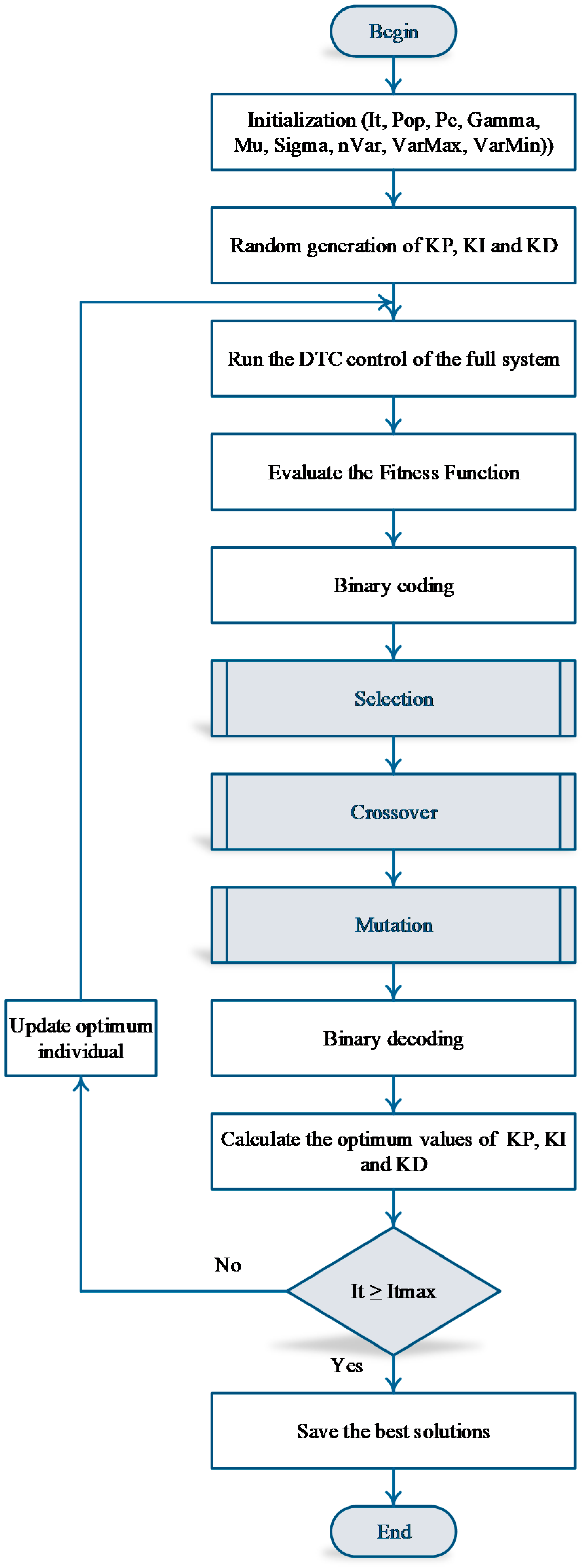
Algorithm 1. Genetic Algorithm
Begin
Step 1. Initialize the algorithm parameters (It, Pop, Pc, gamma, mu, sigma, nVar, VarMax, VarMin).
Step 2. Randomly generate the regulator gains.
Step 3. Apply the DTC control.
Step 4. Evaluate the fitness function instantaneously.
Step 5. Apply binary coding.
Step 6. Move to the selection operation.
Step 7. Move to the crossover operation.
Step 8. Move to the mutation operation.
Step 9. Apply binary decoding.
Step 10. Update the optimal individual and repeat Step 3 until the maximum number of iterations is fulfilled.
Step 11. Save the optimal solutions.
End

5. Simulation Procedure and Interpretation

5.1. Simulation Procedure

Figure 5 depicts the suggested technique for DTC utilizing a PID controller based on GA employing ISE applied to a DFIM.
A simulation of the theoretically given approach was performed using MATLAB/Simulink. The PID controller parameter values optimized by the GA fell within certain variation ranges, as shown in Table 2. Table A1 and Table A2 in the Appendix A show the overall system configuration. The system is also subject to speed and torque reference conditions. The machine used for the two strategies is 1.5 kW, and they are subjected to the conditions of simulation to arrive at a valid comparison. The procedures for implementing the reference instructions are organized as follows:
The overall system consisting of the controls—whether DTC or GA–DTC coupled with a DFIM—is subject to speed and torque references:
  • A speed step of 157 rad/s is applied from 0.7 s to 2.35 s, and then the setpoint begins to decrease in the form of an affine function of negative slope down to −157 rad/s, which presents the opposite direction of rotation. This speed remains constant up to 4.65 s, and then the motor is stopped.
  • During the speed variation, a load torque is applied to the system, which starts with a nominal load torque step of 10 Nm at 1.1–2.1 s, and then the motor remains idle until the instant 3.05–4.25 s, when a negative load torque is applied, which follows the direction of machine rotation.
At the beginning of the system’s operation, the following parameters are set:
  • Sampling frequency: fs =10 kHz.
  • Hysteresis bands widths: ΔTem = ±0.01 Nm, ΔΨs = ΔΨr = ±0.001 Nm.
After several attempts to generate the gains from the PID controllers, the algorithm ultimately converged to its optimum, giving optimal gains that gave the best results for machine performance under DTC. Controller gains from the DTC were generated by the standard synthesis method using the Bode and Nyquist diagrams. Finally, Table 3 illustrates the gains synthesized by the conventional method for the DTC, as well as the optimal optimizer gains by the GA algorithm.
Figure 6, Figure 7, Figure 8, Figure 9, Figure 10, Figure 11, Figure 12, Figure 13, Figure 14, Figure 15, Figure 16, Figure 17 and Figure 18 illustrate the motor performance of both approaches.
Figure 6a–c depict the motor’s speed performances. The speed of the DTC control is represented in red, showing reference tracking throughout the reference setpoint, but representing a speed overshoot value of 60.14 rad/s, as shown in Figure 6a, and the response rejoins its reference, marking a response time of 61.1 ms and an undershoot of 9.826 ms due to the application of the nominal load at the instant of 1.25 s. The response speed is directly linked to its reference, marking a rejection time of 84 ms, as shown in Figure 6b. This response represents an almost-complete reference tracking during the decrease in speed and reversal of the speed rotation, as shown in Figure 6c, but one can notice overshoot and undershoot peaks due to instantaneous speed variation and the sudden application of load torque. According to Figure 6, the response speed of the GA–DTC (in blue) shows absolute tracking of the reference without overshoot and without static error, regardless of the variation in the reference and the load torque, marking several improvements in the DTC speed performance, such as response time, overshoot, reject time, and undershoot, with remarkable rates of 18.66%, 100%, 81.07%, and 51.86%, respectively.
The torque dynamics of the two controls are illustrated in Figure 7. The two responses show a follow-up of the reference setpoint of the fully complete load torque throughout the reference. The responses represent a starting torque of up to 15 Nm, which is normal because of the current demands at the start of rotation and at the sudden instants of increasing speed, whether loaded or unloaded. One can see that the undershoot in the torque presented by the DTC is corrected by the proposed GA–DTC, and is eliminated during the instants 0.7 s and 4.65 s, so one can observe that the DTC presents torque ripples of 2.445 Nm and 2.05 Nm for the GA–DTC, marking an improvement of 16.16%, knowing that the torque ripples are the essential factor determining the life of the DFIM. For example if in our case the motor is predicted to stop working after 10 years with the use of DTC, the lifetime will expand at a rate of 16.16%, i.e., the machine will stop working after 11.616 years, with an addition of 1.616 years as a result ofusing the GA–DTC.
Figure 8, Figure 9 and Figure 10a,b illustrate the stator and rotor currents and their THDs, which determine the harmonic rate in the case of the use of the DTC. It should be noted that the currents are of sinusoidal form, which are harmonics of the THD values of 10.47% and 7.57% for the stator and rotor currents, respectively, generating ripples in the torque of 2.445 Nm. It is known that the harmonics have an influence on the torque ripples. If the THD rate is high, we will see more ripples in the torque, decreasing the motor’s lifetime.
Figure 12, Figure 13 and Figure 14a,b illustrate the stator and rotor currents and their THDs, which determine the harmonic rate in the case of the proposed GA–DTC. It should be noted that the currents are of a sinusoidal form, which is less harmonious compared to the DTC, presenting with THD values of 4.17% and 3.95% for the stator and rotor currents, respectively, generating ripples in the torque of 2.05 Nm. This marks improvements in the THDs, reaching 60.17% and 47.82%, respectively, increasing the motor’s lifetime.
Figure 11a,b and Figure 15a,b show the stator and rotor voltages delivered by the voltage inverters; from the first view it can be noted that the voltages are of the two-level type. Figure 11 and Figure 12 of the DTC are rich in pulses that present undesired harmonics, which occur as torque ripples, increasing the mechanical vibrations of the machine. From Figure 15a,b of the GA–DTC control, it can be seen that the voltages have fewer pulses, allowing voltages close to the ideal voltages, and reducing the torque ripples.
Figure 16 shows the stator and rotor flux characteristics of conventional DTC and GA–DTC, which enhance the flux amplitudes by 29.7% and 24.32%, respectively, when compared to their respective values in Table 4.
When opposed to a classic DTC, the DFIM with GA–DTC reaches its reference torque value in a far shorter amount of time. Furthermore, the torque is carefully regulated in cases where the load fluctuates significantly. In terms of response time, as seen in Figure 7, the proposed DTC based on GA provides a satisfactory response in terms of speed, attaining the target speed with minimal response time and without overshoot. Furthermore, in the case of a rapid change in load, the speed can be managed slowly.
Finally, based on the results of the entire study, the suggested method outperforms the classic DTC. Motor control with low torque ripples may be achieved by using the approach suggested in this paper.
With respect to the previously stated assumptions, as well as the various performances presented in Table 4, the GA–DTC proposed in this article achieves its stated goal by showing its resilience and robustness to speed, fluxes, and torque ripples, as well as currents and THDs.
The DTC enhanced by using GA allows the DFIM to be controlled more reliably under a wider range of operating conditions than previously possible. Due to the fact that the GA–DTC method adjusts to the machine’s parametric fluctuation, it is supposed to be an optimal solution for variable-speed drive applications, as shown above.

5.2. Discussion and Comparison

A number of techniques for controlling the motor at different speeds and torques have been described in the technical literature for the DFIM. As an example, consider the FOC control developed by [6], which is very sensitive to variations in the parameters of the motor. The torque ripples of this strategy are 2.5 Nm, and the response time is 0.56 s. In [43,44], the authors employed the SMC—also known as the chattering phenomena—which limits the robustness of this technique in terms of performance. This method has a torque ripple of 2.5 Nm and a response time of 0.19 s. Because of the drawbacks of the controls outlined above, DTC emerges as the most suited option, and artificial intelligence approaches are among the strategies used to strengthen its resilience. As shown in Table 5, the suggested GA–DTC method enables us to achieve the highest feasible level of performance. The performance of several techniques used in the DFIM is shown in the following table:
The histograms shown in Figure 17 and Figure 18 illustrate the response time of speed and the amplitudes of the torque ripples produced by each approach. On the basis of Figure 17, one can conclude that the fastest controller is the proposed GA–DTC, while on the basis of Figure 18, one can conclude that the proposed strategy is the one with the least amount of ripples.

6. Practical Validation and Interpretation

6.1. Practical Validation

Implementing a realistic solution allows us to evaluate the performance of the GA–DTC nonlinear robust control, and to validate the necessary improvements. The DS1104 “R&D” control board, manufactured by dSPACE and specifically designed for research and development purposes, serves as the basis of the control system. To link between the simulation and the DS1104 board, the Real-Time Interface (RTI) library is installed on the computer, and it is housed inside a physical system as an electrical device on the dSPACE board, which transfers the signals from simulation environment to the real system. The physical system of the board, including the RTI interface, takes care of the application and administration, and generates 0–5V TTL (PWM) logic signals. Suitable isolation of the TTL-CMOS control boards with a supply voltage of 0/15 V is required to operate the inverter IGBTs in conjunction with the TMS320F240 slave DSP. On the computer, a part contains emulating software (MATLAB) that enables the designers to design real-time applications using blocks that have been expressly placed in the Toolbox RTI library, which is included in the software section. The Toolbox RTI library includes blocks specific to the “Real-Time Interface” (RTI) Toolbox and its components. In addition, the RTI allows the adjustment of inputs and outputs through the use of a graphical user interface.
The “R&D DS1104” board is equipped with the Real-Time Workbench (RTW) tool, which is used to compile and transform the source code into an .sdf file. Using a computer loaded with the “ControlDesk” software, the source code that was created and converted to an .sdf file is loaded and executed. This is also used to develop designer interfaces and perform real-time controls, thus archiving programs in fully compatible “Matlab-Simulink” files and allowing observation and real-time monitoring of the system and the evolution of calculated and measured data, among other applications. When creating graphical designer interface prototypes, the following are the main procedures to follow:
  • First of all, the control system is designed using the Simulink modeling program.
  • It is necessary to simulate the system in order to generate several control results, in order to know the control validity.
  • Generation of the .sdf file using the RTI interface.
  • When the global model is run in real time, the DS1104 R&D board is used through the ControlDesk environment with a processor (MPC8240) operating at a clock frequency equal to 250 MHz. An image of the experimental setup and a diagram showing the link between the DS1104 R&D Board and the DFIM are shown in Figure 19 and Figure 20, respectively. In order to perform the experimental test, the control board and the RTW tool are used together.

6.2. Results and Interpretation

It is possible to validate the objectives previously set by the experiment on dSPACE DS1104 by testing the system’s behavior under various working conditions after applying a variable-speed signal in both directions to the proposed GA–DTC and DFIM, either at zero charge or at full charge, using 10 Nm and −10 Nm as the parameters.
Figure 21a,b, as well as Figure 22, Figure 23 and Figure 24, show that the results of the simulations and experiments are identical. When the speed rapidly changes in both directions, the transition from 0 to 157 rad/s and from −157 rad/s to 0 occurs quickly and without exceeding the limit (Figure 21a). When applying a variable torque, temporary changes in the reference values cause the appearance of peaks in the speed profiles, and the stator and rotor currents have a sinusoidal form that varies with the charge (Figure 22 and Figure 23). As shown in the figures, there is excellent agreement between the results of the simulation and the results obtained on the ground during these applications.
Figure 21a,b show the speed response at variable setpoints (from 0 rad/s to 157 rad/s, and from −157 rad/s to 0 rad/s), as shown in the previous figure. Generally speaking, the response times are reasonable (in simulation and in practice). Furthermore, it is important to point out that the speed is set to the specified values, with good dynamic behavior and no detectable exceedances. In addition, there are no static errors, despite the fact that there is a slight increase in torque ripples in practice as a result of the measurement noise and the machine’s parameters, as illustrated in Figure 24.
Figure 25a,b show the control pulses delivered by the switching tables of the GA–DTC, which are delivered to control the inverters of the DFIM at variable frequencies. It can be seen that the pulses are in the form of a variable-frequency pulse train, to control the inverters and the DFIM according to the variation of the speed and load.
The circular flux curves of the stator and rotor are shown in Figure 26, which demonstrates that the fluxes are maintained within a specified range determined by the hysteresis comparator’s range. The results obtained are consistent with those obtained as a result of simulating the situation.
Figure 26a,b show the stator and rotor voltages delivered by the voltage inverters, respectively; at first glance, the voltages appear to be similar to the voltages found by simulation, indicating that they are harmonized with fewer harmonics than the classical DTC.
Finally, we can summarize the advantages and disadvantages of using optimization algorithms such as the GA used in this study, as follows:
Advantages:
-
Allows an optimal reference monitoring profile.
-
Adaptation with a sudden change in front of a system’s internal and external disturbances.
-
Rapid optimization of the gains of a regulator such as the PID
-
Can be used as an estimator of parameters sensitive to physical variations.
Disadvantages:
-
Convergence of solutions towards local solutions.
-
Estimates of the parameters of the genetic algorithm, such as the population size and the number of iterations; requires more than two weeks to have a reduced execution time with optimal gains.

7. Conclusions

A Genetic-Algorithm-based PID optimization algorithm for DTC applied to a DFIM was developed. This configuration was simulated in MATLAB/Simulink and practically validated using a dSPACE DS1104testboard. This study shows an enhancement of the dynamics of classic DTC via optimizing and updating the PID coefficients KP, KI, and KD in each interval to adapt to the system nonlinearity. The proposed GA–DTC control demonstrated significant improvements in speed overshoot and rejection time, fluxes and torque ripples, and current THD. The following items highlight the improvements made to the DFIM’s performance:
  • Reducing the speed overshoot, with and without load torque.
  • Reducing the disturbance rejection time by 81.07%.
  • Minimizing the ripples of the stator and rotor fluxes, as well as torque ripples, with improvements of 29.71%, 24.32%, and 16.16%, respectively.
  • Acceptable enhancements in the current THDs, by 60.17% and 47.82%, respectively.
  • The practical validation findings obtained using ControlDesk confirmed the simulated results obtained via MATLAB/Simulink.
A significant improvement was shown in the proposed technique in the form of faster response, fewer ripples, and higher precision and robustness, confirming the achievement of the targets outlined earlier in this paper.
With a view to advancing the technological research conducted in the laboratory, our research team has chosen to undertake the following tasks as part of its future work:
  • Validation of ANN–DTC for DFIMs using a dSPACE board.
  • Elaboration of the review of the techniques applied to DFIMs.

Author Contributions

Conceptualization, S.M., M.A.M. and N.E.O.; methodology, S.M., A.D., N.K.L. and M.S.B.; software, S.M. and M.A.M.; validation, S.M., M.A.M., N.V.Q. and N.E.O.; formal analysis, S.M., M.A.M., S.M. and M.S.B. investigation, S.M., A.D., N.E.O., N.K.L. and N.V.Q.; resources, S.M., M.A.M., N.E.O. and A.D.; data curation, S.M., A.D., N.K.L. and M.S.B.; writing—original draft preparation, S.M. and M.A.M.; writing—review and editing, S.M., M.A.M., N.V.Q. and M.S.B.; visualization, S.M., M.A.M. and S.M.; supervision, S.M., A.D. and M.A.M.; project administration, S.M., M.A.M., A.D. and N.V.Q.; funding acquisition, M.A.M., N.E.O. and N.V.Q. All authors have read and agreed to the published version of the manuscript.

Funding

This study was funded equally by the Ministry of Higher Education in Egypt, Hassan First University in Morocco, and Lac Hong University in Vietnam.

Institutional Review Board Statement

Not applicable.

Informed Consent Statement

Not applicable.

Data Availability Statement

The data presented in the paper are available upon request from the corresponding author (M.A.M.).

Conflicts of Interest

The authors declare no conflict of interest.

Appendix A

Table A1. Specifications of the DFIM.
SymbolsValues (Unit)
P n 1.5 Kw
V s 400 v
V r 130 v
P 2
f 50 Hz
R s 1.75 Ω
R r 1.68 Ω
L s 0.295 H
L r 0.104 H
M 0.165 H
f 0.0027 kg·m2/s
J 0.01 kg·m2
Table A2. GA parameters.
DescriptionsTypes/Values
Population Size20
Maximum Iterations50
Crossover Probability0.9
Mutation Probability0.001
Beta1
Sigma0.1
Gamma0.1
CodingBinary
SelectionUniform
CrossoverRoulette Wheel Selection
MutationUniform
Table A3. Nomenclature.
ParametersDescription
V, V, V, and V(α, β) Components of Stator and Rotor Voltages
Udcs and UdcrStator and Rotor Direct Voltages
I, I, I, and I(α, β) Components of Stator and Rotor Currents
Ψ, Ψ, Ψ, and Ψ(α, β) Components of Stator and Rotor Fluxes
Rs, RrResistances of Stator and Rotor Windings
Ls, LrInductances of Stator and Rotor Windings
LmMagnetizing Inductance
pPole Pairs
ωrAngular Rotor Speed
ωsAngular Stator Frequency
Rotational Speed
TemDeveloped Torque
TrEncounteredTorque
fFriction
JMotor Inertia
Table A4. Abbreviations table.
AbbreviationsWording
DFIMDoubly-Fed Induction Motor
IMInduction Machine
DCDirect Current
THDTotal Harmonic Distortion
DTCDirect Torque Control
GAGenetic Algorithm
GA-DTCGenetic Algorithm–Direct Torque Control
CLFTClosed-Loop Function Transfer
PIDProportional–Integral–Derivative
DTFCDirect Torque Fuzzy Control
DTNCDirect Torque Neural Control
DTNFCDirect Neural Fuzzy Torque Control
ANFISAdaptive Neuro-Fuzzy Inference System
RTIReal-Time Interface
R&DResearch and Development
RTWReal-Time Workbench
CPControl Panel
PWMPulse-Width Modulation

References

  1. Mahfoud, S.; Derouich, A.; Iqbal, A.; El Ouanjli, N. ANT-colony optimization-direct torque control for a doubly fed induction motor: An experimental validation. Energy Rep. 2022, 8, 81–98. [Google Scholar] [CrossRef]
  2. Mahfoud, S.; Derouich, A.; El Ouanjli, N.; Mohammed, T.; Hanafi, A. Field Oriented Control of Doubly Fed Induction Motor using Speed Sliding Mode Controller. In E3S Web of Conferences, Proceedings of the 3rd International Conference of Computer Science and Renewable Energies, Agadir, Morocco, 22–24 December 2020.; EDP Sciences: Les Ulis, France, 1920; Volume 220, p. 01061. [Google Scholar]
  3. Mossa, M.A.; Abdelhamid, M.K.; Hassan, A.A.; Bianchi, N. Improving the Dynamic Performance of a Variable Speed DFIG for Energy Conversion Purposes Using an Effective Control System. Processes 2022, 10, 456. [Google Scholar] [CrossRef]
  4. Mossa, M.A.; Al-Sumaiti, A.S.; Do, T.D.; Diab, A.A.Z. Cost-Effective Predictive Flux Control for a Sensorless Doubly Fed Induction Generator. IEEE Access 2019, 7, 172606–172627. [Google Scholar] [CrossRef]
  5. Mahfoud, S.; Derouich, A.; El Ouanjli, N.; Quynh, N.V.; Mossa, M.A. A New Hybrid Ant Colony Optimization Based PID of the Direct Torque Control for a Doubly Fed Induction Motor. World Electr. Veh. J. 2022, 13, 78. [Google Scholar] [CrossRef]
  6. Mahfoud, S.; Derouich, A.; EL Ouanjli, N.; EL Mahfoud, M.; Taoussi, M. A New Strategy-Based PID Controller Optimized by Genetic Algorithm for DTC of the Doubly Fed Induction Motor. Systems 2021, 9, 37. [Google Scholar] [CrossRef]
  7. El Ouanjli, N.; Derouich, A.; El Ghzizal, A.; Chebabhi, A.; Taoussi, M. A comparative study between FOC and DTC control of the Doubly Fed Induction Motor (DFIM). In Proceedings of the 2017 International Conference on Electrical and Information Technologies (ICEIT), Rabat, Morocco, 15–18 November 2017; IEEE: Piscataway, NJ, USA, 1963; pp. 1–6. [Google Scholar]
  8. Mossa, M.A.; Bolognani, S. Effective sensorless model predictive direct torque control for a doubly fed induction machine. In Proceedings of the 2017 IEEE Nineteenth International Middle East Power Systems Conference (MEPCON), Cairo, Egypt, 19–21 December 2017; pp. 1201–1207. [Google Scholar]
  9. Mossa, M.A.; Mohamed, Y.S. Novel Scheme for Improving the Performance of a Wind Driven Doubly Fed Induction Generator during Grid Fault. Wind Eng. 2012, 36, 305–334. [Google Scholar] [CrossRef]
  10. Mahfoud, S.; Derouich, A.; Ouanjli, N.E.; Taoussi, M.; Mahfoud, M.E. Improved DTC of the PID Controller by Using Genetic Algorithm of a Doubly Fed Induction Motor. In Digital Technologies and Applications, Proceedings of the Lecture Notes in Networks and Systems, Fez, Morocco, 28–30 January 2022; Motahhir, S., Bossoufi, B., Eds.; Springer: Cham, Switzerland, 2022; Volume 211, pp. 1687–1698. [Google Scholar]
  11. Hassan, A.; Mohamed, Y.S.; El-Sawy, A.; Mossa, M.A. Control of a Wind Driven DFIG Connected to the Grid Based on Field Orientation. Wind Eng. 2011, 35, 127–143. [Google Scholar] [CrossRef]
  12. Mossa, M.A.; Echeikh, H.; Iqbal, A. Enhanced control technique for a sensor-less wind driven doubly fed induction generator for energy conversion purpose. Energy Rep. 2021, 7, 5815–5833. [Google Scholar] [CrossRef]
  13. Mahfoud, S.; Derouich, A.; El Ouanjli, N.; El Mahfoud, M. Enhancement of the Direct Torque Control by using Artificial Neuron Network for a Doubly Fed Induction Motor. Intell. Syst. Appl. 2022, 13, 200060. [Google Scholar] [CrossRef]
  14. Blaschke, F. The principle of field oriented as applied to the new transvector closed-Iloop control system for rotating machines. Siemens Rev. 1972, 139, 217–220. [Google Scholar]
  15. Mossa, M.A. Field Orientation Control of a Wind Driven DFIG Connected to the Grid. Wseas Trans. Power Syst. 2012, 4, 182–197. [Google Scholar]
  16. Mahfoud, S.; Derouich, A.; El Ouanjli, N.; El Idrissi, A.; El Mahfoud, M. Optimized PID Controller by Ant Colony Optimization of DTC for Doubly Fed Induction Motor. In Proceedings of the International Conference on Digital Technologies and Applications, Fez, Morocco, 28–30 January 2022; Springer: Cham, Switzerland; pp. 767–778. [Google Scholar]
  17. Mossa, M.A.; Bolognani, S. Predictive Power Control for a Linearized Doubly Fed Induction Generator Model. In Proceedings of the 2019 21st International Middle East Power Systems Conference (MEPCON), Cairo, Egypt, 17–19 December 2019; pp. 250–257. [Google Scholar]
  18. Mahfoud, S.; Derouich, A.; El Ouanjli, N. Performance Improvement of DTC for Doubly Fed Induction Motor by Using Artificial Neuron Network. In Proceedings of the International Conference on Digital Technologies and Applications, Fez, Morocco, 28–30 January 2022; Springer: Cham, Switzerland, 2022; pp. 32–42. [Google Scholar]
  19. Hamidia, F.; Abbadi, A.; Skender, M.R. Pumping FOC-DFIM System Supplied with PVG and Based on FLC Type-2. In Advances in Green Energies and Materials Technology; Springer: Singapore, 2021; pp. 87–93. [Google Scholar]
  20. Takahashi, I.; Ohmori, Y. High-performance direct torque control of an induction motor. IEEE Trans. Ind. Appl. 1989, 25, 257–264. [Google Scholar] [CrossRef]
  21. Takahashi, I.; Noguchi, T. Take a look back upon the past decade of direct torque control [of induction motors]. In Proceedings of the IECON’97 23rd International Conference on Industrial Electronics, Control, and Instrumentation, New Orleans, LA, USA, 14 November 1997; Volume 2, pp. 546–551. [Google Scholar]
  22. Das, K.R.; Das, D.; Das, J. Optimal tuning of PID controller using GWO algorithm for speed control in DC motor. In Proceedings of the 2015 International Conference on Soft Computing Techniques and Implementations (ICSCTI), Faridabad, India, 8–10 October 2015; IEEE: Piscataway, NJ, USA, 2015; pp. 108–112. [Google Scholar]
  23. Madadi, A.; Motlagh, M.M. Optimal control of DC motor using grey wolf optimizer algorithm. Tech. J. Eng. Appl. Sci. 2014, 4, 373–379. [Google Scholar]
  24. Kanojiya, R.G.; Meshram, P.M. Optimal tuning of PI controller for speed control of DC motor drive using particle swarm optimization. In Proceedings of the 2012 International Conference on Advances in Power Conversion and Energy Technologies (APCET), Mylavaram, Andhra Pradesh, India, 2–4 August 2012; IEEE: Piscataway, NJ, USA; pp. 1–6. [Google Scholar]
  25. Ayala, H.V.H.; dos Santos Coelho, L. Tuning of PID controller based on a multiobjective genetic algorithm applied to a robotic manipulator. Expert Syst. Appl. 2012, 39, 8968–8974. [Google Scholar] [CrossRef]
  26. Krohling, R.A.; Rey, J.P. Design of optimal disturbance rejection PID controllers using genetic algorithms. IEEE Trans. Evol. Comput. 2001, 5, 78–82. [Google Scholar] [CrossRef]
  27. Nagaraj, B.; Murugananth, N.A. Comparative study of PID controller tuning using GA, EP, PSO and ACO. In Proceedings of the 2010 International Conference on Communication Control And Computing Technologies, Nagercoil, India, 7–9 October 2010; IEEE: Piscataway, NJ, USA, 2010; pp. 305–313. [Google Scholar]
  28. Holland, J.H. Adaptation in Natural and Artificial Systems: An Introductory Analysis with Applications to Biology, Control, and Artificial Intelligence; MIT press: Cambridge, MA, USA, 1992; p. 211. [Google Scholar]
  29. Goldberg, D.E. Sizing populations for serial and parallel genetic algorithms. In Proceedings of the 3rd international conference on genetic algorithms, George Mason University, Fairfax, VA, USA, 4–7 June 1989; pp. 70–79. [Google Scholar]
  30. Reeves, C.R. Using Genetic Algorithms with Small Populations. In Proceedings of the ICGA, Champaign, IL, USA, 17–21 June 1993; Volume 590, p. 92. [Google Scholar]
  31. El Mahfoud, M.; Bossoufi, B.; El Ouanjli, N.; Mahfoud, S.; Taoussi, M. Three speed controllers of direct torque control for a doubly fed induction motor drive–A comparison. Electrica 2021, 21, 129–142. [Google Scholar] [CrossRef]
  32. El Ouanjli, N.; Mahfoud, S.; Bhaskar, M.S.; El Daoudi, S.; Derouich, A.; El Mahfoud, M. A new intelligent adaptation mechanism of MRAS based on a genetic algorithm applied to speed sensorless direct torque control for induction motor. Int. J. Dyn. Control. 2022, 1–16. [Google Scholar] [CrossRef]
  33. Meena, D.C.; Devanshu, A. Genetic algorithm tuned PID controller for process control. In Proceedings of the 2017 International Conference on Inventive Systems and Control (ICISC), Coimbatore, India, 19–20 January 2017; pp. 1–6. [Google Scholar]
  34. Amirjanov, A. The parameters setting of a changing range genetic algorithm. Nat. Comput. 2015, 14, 331–338. [Google Scholar] [CrossRef]
  35. Mohammed, E.M.; Badre, B.; Najib, E.O.; Abdelilah, H.; Houda, E.A.; Btissam, M.; Said, M. Predictive Torque and Direct Torque Controls for Doubly Fed Induction Motor: A Comparative Study. In Proceedings of the International Conference on Digital Technologies and Applications, Fez, Morocco, 28–30 January 2022; Springer: Cham, Switzerland, 2022; pp. 825–835. [Google Scholar]
  36. El Mahfoud, M.; Bossoufi, B.; El Ouanjli, N.; Said, M.; Taoussi, M. Improved direct torque control of doubly fed induction motor using space vector modulation. Int. J. Intell. Eng. Syst 2021, 14, 177–188. [Google Scholar] [CrossRef]
  37. Chlaihawi, A.A. Genetic algorithm error criteria as applied to PID controller DC-DC buck converter parameters: An investigation. In IOP Conference Series: Materials Science and Engineering, Proceedings of the 3rd International Conference on Engineering Sciences, Kerbala, Iraq, 4–6 November 2019; IOP Publishing: Bristol, UK, 2020; Volume 671, p. 012032. [Google Scholar] [CrossRef]
  38. Grefenstette, J.J. Optimization of control parameters for genetic algorithms. IEEE Trans. Syst. Man Cybern. 1986, 16, 122–128. [Google Scholar] [CrossRef]
  39. El Mahfoud, M.; Bossoufi, B.; El Ouanjli, N.; Mahfoud, S.; Yessef, M.; Taoussi, M. Speed Sensorless Direct Torque Control of Doubly Fed Induction Motor Using Model Reference Adaptive System. In Proceedings of the International Conference on Digital Technologies and Applications, Fez, Morocco, 28–30 January 2022; Springer: Cham, Switzerland, 2022; pp. 1821–1830. [Google Scholar]
  40. Bharadwaj, C.S.; Babu, T.S.; Rajasekar, N. Tuning PID Controller for Inverted Pendulum Using Genetic Algorithm. In Advances in Systems, Control and Automation; Springer: Singapore, 2018; pp. 395–404. [Google Scholar]
  41. El Idrissi, A.; Derouich, A.; Mahfoud, S. Fault Diagnosis of the Bearing Outer Ring of an Induction Motor Under DTC Control by Using Hilbert Filter. In Proceedings of the International Conference on Digital Technologies and Applications, Fez, Morocco, 28–30 January 2022; Springer: Cham, Switzerland, 2022; pp. 802–812. [Google Scholar]
  42. Robertson, G.G. Population size in classifier systems. In Machine Learning Proceedings1988; Morgan Kaufmann: Burlington, MA, USA, 1988; pp. 142–152. [Google Scholar]
  43. Abderazak, S.; Farid, N. Comparative study between Sliding mode controller and Fuzzy Sliding mode controller in a speed control for doubly fed induction motor. In Proceedings of the 2016 4th International Conference on Control Engineering & Information Technology (CEIT), Hammamet, Tunisia, 16–18 December 2016; IEEE: Piscataway, NJ, USA, 2016; pp. 1–6. [Google Scholar]
  44. El Ouanjli, N.; Mahfoud, S.; Derouich, A.; El Daoudi, S.; El Mahfoud, M. Speed Sensorless Fuzzy Direct Torque Control of Induction Motor Based MRAS Method. In Proceedings of the International Conference on Digital Technologies and Applications, Fez, Morocco, 28–30 January 2022; Springer: Cham, Switzerland, 2022; pp. 779–790. [Google Scholar]
Figure 1. Proposal structure of DTC based on GA for DFIM.
Energies 15 05384 g001
Figure 2. Optimization of the PID controller parameters by the GA.
Energies 15 05384 g002
Figure 3. Chromosome structure created for a PID controller.
Energies 15 05384 g003
Figure 4. GA flowchart.
Energies 15 05384 g004
Figure 5. GA–DTC schematic applied to a DFIM.
Energies 15 05384 g005
Figure 6. Speed responses (ad) of both strategies.
Energies 15 05384 g006
Figure 7. Torque dynamics of the DTC and GA–DTC.
Energies 15 05384 g007
Figure 8. Stator currents (ac) of the DTC.
Energies 15 05384 g008
Figure 9. Rotor currents (ac) of the DTC.
Energies 15 05384 g009
Figure 10. Stator (a) and rotor (b) current THD of the DTC.
Energies 15 05384 g010
Figure 11. Stator Vsa (a) and rotor Vra (b) voltages of the DTC.
Energies 15 05384 g011
Figure 12. Stator currents (ac) of the GA–DTC.
Energies 15 05384 g012
Figure 13. Rotor currents (ac) of the GA–DTC.
Energies 15 05384 g013
Figure 14. Stator (a) and rotor (b) current THD of the GA–DTC.
Energies 15 05384 g014
Figure 15. Stator Vsa (a) and rotor Vra (b) voltages of the GA–DTC.
Energies 15 05384 g015
Figure 16. Stator (a) and rotor (b) fluxes of both strategies.
Energies 15 05384 g016
Figure 17. Histogram of various responses time of different strategies applied to the DFIM.
Energies 15 05384 g017
Figure 18. Histogram of various torque ripples of different strategies applied to the DFIM.
Energies 15 05384 g018
Figure 19. Image of the test bench.
Energies 15 05384 g019
Figure 20. Global structure of the test bench.
Energies 15 05384 g020
Figure 21. Speed (a) and torque (b) of the GA–DTC.
Energies 15 05384 g021
Figure 22. (a) Stator currents of the GA–DTC; (b,c) zooms of currents from 0.9 s to 1.2 s, and from 1.9 s to 2.2 s, respectively.
Energies 15 05384 g022
Figure 23. Stator currents of the GA–DTC; (ac) zooms of currents from 0.9 s to 1.2 s and from 1.9 s to 2.2 s, respectively.
Energies 15 05384 g023
Figure 24. Isofluxes under GA–DTC: (a) stator and (b) rotor.
Energies 15 05384 g024
Figure 25. Inverter control pulses of the stator (a) and rotor (b) of the GA–DTC.
Energies 15 05384 g025
Figure 26. Stator Vsa (a) and rotor Vra (b) voltages of the GA–DTC.
Energies 15 05384 g026
Table 1. Voltage vector switching.
Sector Si
H ψ s or   H ψ r H t e m S1(Sa Sb Sc)S2(Sa Sb Sc)S3(Sa Sb Sc)S4(Sa Sb Sc)S5(Sa Sb Sc)S6(Sa Sb Sc)
11v2(110)v3(010)v4(011)v5(001)v6(101)v1(100)
0v7(111)v0(000)v7(111)v0(000)v7(111)v0(000)
−1v6(101)v1(100)v2(110)v3(010)v4(011)v5(001)
01v3(010)v4(011)v5(001)v6(101)v1(100)v2(110)
0v0(000)v7(111)v0(000)v7(111)v0(000)v7(111)
−1v5(001)v6(101)v1(100)v2(110)v3(010)v4(011)
Table 2. The PID parameter bands.
PID ParametersKPKIKD
Maximum Value10011
Minimum Value0−1−1
Table 3. Synthesis and optimized PID gains for DTC and the proposed GA–DTC.
Controller ParametersClassic DTCGA–DTC
KP0.77672.8895
KI28.740.0729
KD00.5262
Table 4. Performance measures of classic DTC and GA–DTC.
PerformancesCharacteristicsDTCGA–DTCImprovements (%)
Response Time (ms)61.149.718.66
Overshoot (rad/s)60.140100
Rejection Time (ms)8415.981.07
Undershoot (rad/s)9.8264.7351.86
T Ripples (Nm)2.4452.0516.16
ψ s Ripples (wb)0.061230.0430429.71
ψ r Ripples (wb)0.01180.0089324.32
i s a THD (%)10.474.1760.17
i r a THD (%)7.573.9547.82
Table 5. Comparison between our proposed approach and some control strategies published recently.
Publication ApproachesResponse Time (s)Torque Ripples (Nm)Robustness
[6]Field-Oriented Control0.562.5Not Robust
[40]Sliding Mode Control0.192.4Not Robust
Studied in This WorkClassical DTC0.05072.445Robust
[41]FL–DTC0.281.14Robust
Proposed TechniqueGA–DTC0.04972.05Robust
Publisher’s Note: MDPI stays neutral with regard to jurisdictional claims in published maps and institutional affiliations.

