Article

A 10 kV/1 MW High-Frequency-Isolated Power Conversion System for Battery Energy

Guangzhou Institute of Energy Conversion, Chinese Academy of Sciences, Guangzhou 510642, China
*
Author to whom correspondence should be addressed.
Energies 2022, 15(14), 5272; https://doi.org/10.3390/en15145272
Submission received: 14 June 2022 / Revised: 11 July 2022 / Accepted: 13 July 2022 / Published: 20 July 2022
(This article belongs to the Special Issue Power Quality Analysis and Control of Railway Power Supply Systems)

Abstract

:
Energy storage technology has become critical for supporting China’s large-scale access to renewable energy. As the interface between the battery energy storage system (BESS) and power grid, the stability of the PCS (power conversion system) plays an essential role. Here, we present a topology of a 10 kV high-voltage energy storage PCS without a power frequency transformer for the establishment of a large-scale energy storage system. We analyzed the energy storage converter’s mechanism and characteristics and also introduced the power-control strategy of the HVAC (high-voltage AC) and LVDC (low-voltage DC) converter module. On this basis, a 10 kV/1 MW high-capacity PCS prototype was designed. Additionally, by simulation and experiment, we proved the correctness of the PCS scheme. The topology and control strategy proposed in this paper can provide cases and technical support for the subsequent promotion and application of new energy and power station energy storage.

1. Introduction

Driven by the goal of “carbon peaking and carbon neutralization”, renewable energy technologies such as PV (photovoltaic) and wind power are developing rapidly. It is estimated that in 2030, the installed capacity of non-aqueous renewable energy will account for 43% of China’s total installed capacity. However, renewable energy is random, volatile and uncertain. This would seriously affect the safety and stability of the power grid operation. Energy storage can solve the power grid’s requirements of transient stability and short-term power balance and can be used for long-term power regulation. It can effectively deal with the systemic peak valley regulation and blocking of transmission and distribution lines [1,2].
A PCS can schedule and support the bidirectional flow of electric energy on demand under different operation modes, which is the core equipment supporting the operation of energy storage [3].
Large-scale energy storage is favorable currently. The capacity expansion needs to be realized by the parallel connection of multiple low-voltage small-capacity PCSs and connected to a medium- or high-voltage power grid through the transformer. The connection would lead to the problems of low efficiency, high cost and unnecessary land occupation. In addition, the parallel connecting of multiple PCSs also has the stability risk of circulating current and resonance [3,4]. Therefore, the key research directions of energy storage PCSs are high-voltage access, single-machine large capacity and modularization.
Some scholars have proposed cascaded modular topology in terms of topology [5,6]. The cascaded H-bridge (CHB) converter obtains the most attention and applications due to its good performance. CHB is challenging to adapt to multiple types of energy storage batteries, and the double fundamental frequency fluctuation in the BESS will reduce the battery life [7,8,9]. The topology composed of an H-bridge and DC/DC converter, such as a non-isolated buck-boost circuit, can suppress the BESS’s double frequency power fluctuation. The adaptability of CHB to BESS has also been improved. However, the battery pack is in a high-voltage suspension state without electrical isolation; its common-mode current causes electromagnetic compatibility problems and significantly increases the insulation cost. The topology composed of an H-bridge and isolated DC/DC converter is suitable for accessing a low-voltage battery pack [10,11,12]. The system is safer and more flexible, which covers an in-demand research issue in recent years [13,14,15,16,17,18,19,20]. For the PV grid-connected system, references [19,20] propose a topology based on isolated DC converters to meet the insulation requirements of photovoltaic systems connected to medium-voltage power grids. For the energy storage system, a high-frequency isolated topology is proposed, and the SiC-MOSFET module and prototype are developed [21].
Regarding the device research and development, in 2014, Professor Hirofumi Akagi of the Tokyo Institute of Technology proposed a modular multilevel cascade converter (MMCC) topology of high-voltage direct hanging energy storage system and developed a 6.6 kV/500 kW SSBC (single-star bridge-cell)-based MMCC for BESSs [18]. In China, Shanghai Jiaotong University and China Southern Power Grid proposed a transformer-less high-voltage PCS in 2014. A set of 10 kV/2 MW/2 MWh device prototypes has been developed and applied in Baoqing energy storage power station of the China Southern Power Grid [22]. In 2022, the South China University of Technology and State Grid Corporation of China proposed a PCS topology with an online bypass function based on H-bridge. They developed a 10 kV/2 MW medium-voltage direct-hanging energy storage converter [23]. The above prototypes adopt non-isolated topology or power frequency isolated topology.
To sum up, the topology generally adopts the non-isolation structure based on MMC topology and CHB topology, as well as the isolation structure using an H-bridge and high-frequency transformer. The former has a higher applicable voltage level, while the latter has certain advantages in insulation cost, device volume and safety. It can be popularized and applied to PV, wind power grid connection, power grid peak shaving and frequency modulation, electric vehicle V2G [24], etc.
On the basis of the literature [21], this paper proposes a high-frequency isolated energy storage PCS, which does not need a power-frequency isolation transformer. Cascaded H-bridge converter topology, in comparison, can effectively reduce insulation costs and increase system security. Firstly, the proposed topology’s working principle and converter characteristics are analyzed. Additionally, the power control strategy of the HVAC (high-voltage AC) and LVDC (low-voltage AC) converter modules are introduced. Finally, the application of SiC-MOSFET power devices is explored, a 10 kV/1 MW high-capacity PCS prototype is built, and the simulation and experimental results show the feasibility and effectiveness of the proposed topology and control strategy.
The topology and control strategy of the high-voltage energy storage converter with higher energy efficiency and smaller volume are proposed, which can provide cases and technical support for the promotion and application of subsequent new energy and power station energy storage, so as to promote the development of the large-scale energy storage industry.

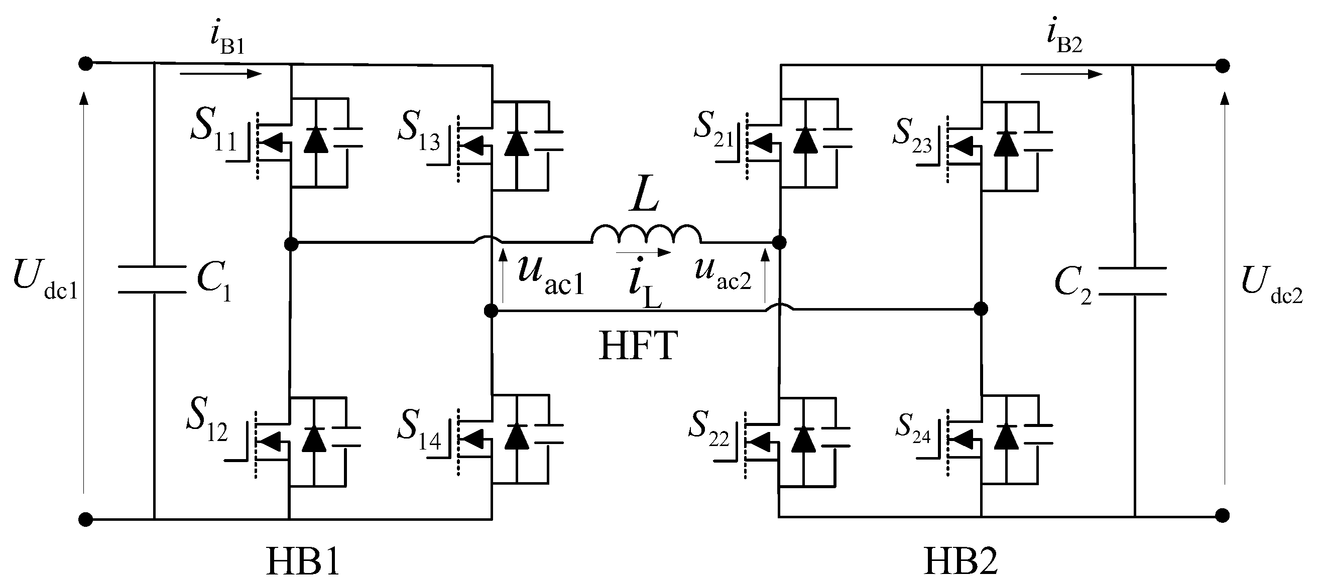
2. Main Circuit Topology and Working Principle of PCS

Main Circuit Topology

Figure 1 shows the topology of a high-frequency isolated large-capacity energy storage system. The PCS adopts the star-connection mode, A,B,C represents the three phases of the power grid, and each phase is cascaded by multiple power modules. Each power module is composed of an H-bridge power converter, bidirectional DAB (dual active bridge) DC/DC conversion unit, battery pack and supporting drive circuit, capacitor, voltage equalizing resistance, etc. HVAC modules are connected in series, and some LVDC modules are connected to batteries in groups, and the reactor is connected in series to realize filtering.
The DAB module is the primary function module of the topology, which realizes the DC bidirectional converter and isolation, as shown in Figure 2. Each DAB module consists of two sets of H-bridges, an HFT (high-frequency transformer), and corresponding capacitor components C1 and C2 [21]. The leakage inductance of HFT is the key to realizing the ZVS (Zero Voltage Switch) under phase-shifting control [25,26]. In Figure 2, Udc1 and Udc2 are DC voltages at both ends of the converter, Uac1 and Uac2 are the HFT primary and secondary AC voltages, iT1 and iT2 are the HFT primary and secondary AC currents, n = N1/N2 represents the transformation ratio of HFT, and S11–S24 are power electronic devices.
The DAB module adopts single-phase-shift control mode, and the phase angle of the HB2 driving signal is φ degrees later than HB1. The bidirectional energy flow of HB1 and HB2 can be realized by adjusting the polarity of the phase-shift angle φ.
When the voltage phase of the bridge arm is ahead of the AC power supply, the energy storage system is in discharge operation state. On the contrary, when the voltage phase of the bridge arm lags behind the voltage phase of the AC power grid, the energy storage is in charging state. The charge and discharge power is determined by the phase-shift angle φ [21].
The equivalent circuit of DAB is shown in Figure 3, wherein Udc1 is the DC-side voltage of H-bridge on the grid side; Udc2 is the DC voltage at the battery side; uac1 and uac2 represent HB1 and HB2 high-frequency AC voltage, respectively; L represents HFT leakage inductance reduced to Udc1 side; and iL represents HFT high-frequency current.
The high-frequency AC part can be expressed as:
d i L ( t ) d t = u a c 1 ( t ) u a c 2 ( t ) L
Ths represents half a switching cycle:
T hs = 1 2 T s
Then the average transmission power in one switching cycle Ts is:
P = 1 T s 0 T s u a c 1 ( t ) i L ( t ) d t = n U d c 1 U d c 2 φ ( 1 | φ | ) T hs L
where n is the HFT transformation ratio and φ is the phase-shift angle, assuming that:
k = U d c 1 n U d c 2
Then, the maximum current of the transformer is:
i max = n U d c 2 4 f s L ( 2 φ + k 1 )
The switching frequency is:
f s = 1 2 T h s
In order to analyze the influencing factors and change the trend of transmission power, PB is taken as the reference value of power to obtain the unit value P′ of transmission power, and the following formula is obtained:
P B = n U d c 1 U d c 2 8 f s L
P = P P B = 4 φ ( 1 φ )
Equation (8) shows that the transmission power changes with the change in φ, and the relationship between transmission power and φ is shown in Figure 4. It can be seen that when φ is 0.5, the power reaches its peak.

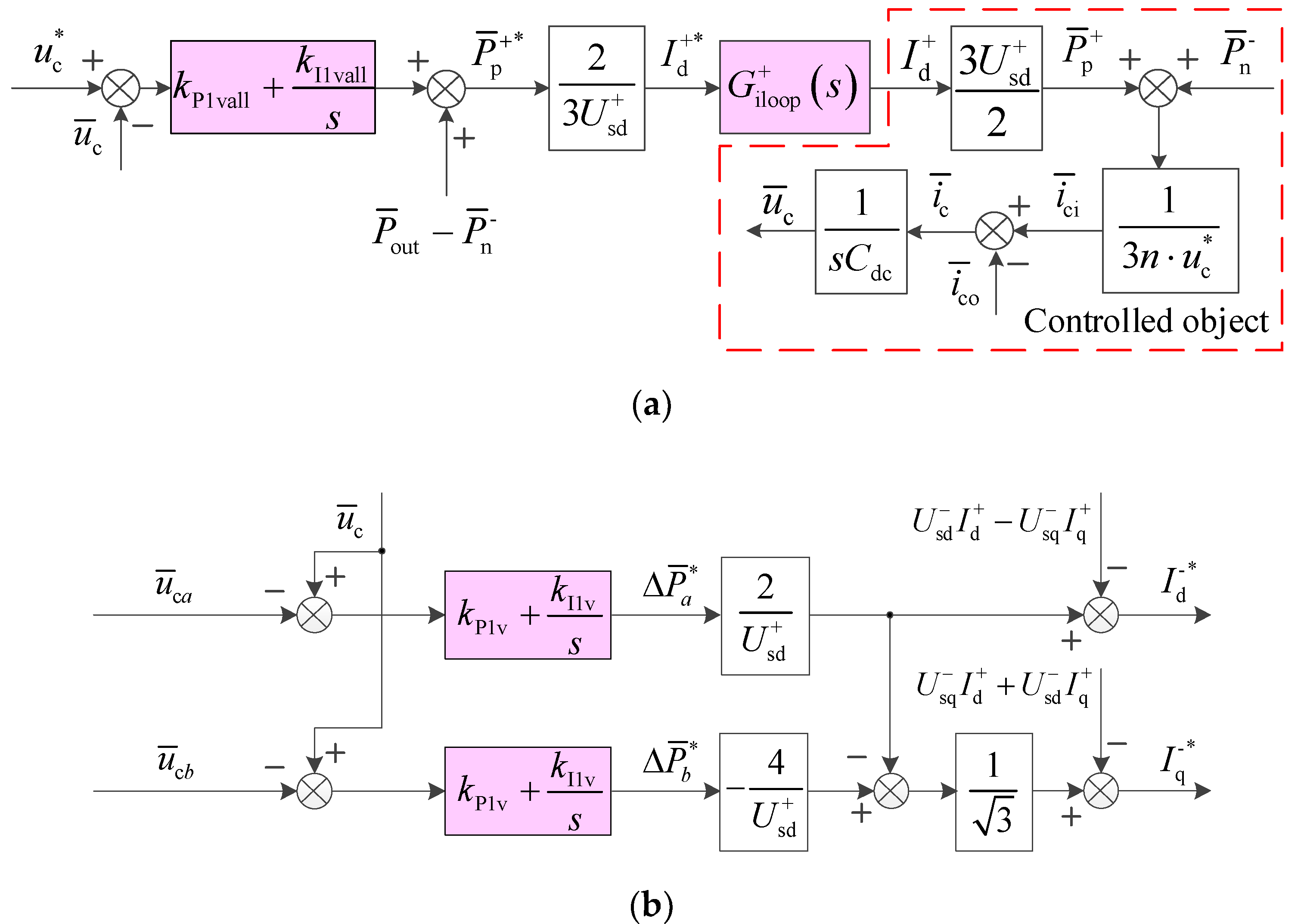
3. PCS Control Strategy

3.1. HVAC Port Control Strategy

A power decoupling control strategy is proposed for the HVAC port of the PCS; the phase voltages (usag, usbg and uscg) of the PCS can be expressed as:
u s = u s + + u s + u s t h = u s + + u s + h = 6 k ± 1 k = 1 , 2 , 3 u s h
In Equation (9), u s + and u s represent the positive sequence and negative sequence components of the fundamental wave, respectively, u s t h is the high-order harmonic component, h = 6k ± 1 is the harmonic number, and k is a positive integer with the value of 1, 2, or 3.
The input current of the PCS can be expressed as:
i = i + + i + i t h = i + + i + h = 6 k ± 1 k = 1 , 2 , 3 i h
The three-phase average active power of the HVAC port can be expressed as:
P ¯ = [ P ¯ a P ¯ b P ¯ c ] T = P ¯ + + P ¯ = P ¯ p + + P ¯ n + + P ¯ n + P ¯ p
In Equation (11), superscript “+” and “−” represent the positive sequence current component and negative sequence current component, respectively, and subscripts p and n represent the positive sequence voltage component and negative sequence voltage component, respectively. Taking P ¯ p + as an example, it represents the instantaneous active power flow generated by positive sequence current i+ and positive sequence voltage u s + . Each power component can be expressed as voltage and current components in the dq coordinate system:
P ¯ p + = [ P ¯ p a + P ¯ p b + P ¯ p c + ] = [ ( U s d + I d + + U q + I q + ) / 2 ( U s d + I d + + U s q + I q + ) / 2 ( U s d + I d + + U s q + I q + ) / 2 ]
P ¯ n + = [ P ¯ n a + P ¯ n b + P ¯ n c + ] = 1 4 [ 2 U s d 2 U s q U s d 3 U s q U s q 3 U s d U s d + 3 U s q U s q + 3 U s d ] [ I d + I q + ]
P ¯ n = [ P ¯ n a P ¯ n b P ¯ n c ] = [ ( U s d I d + U s q I q ) / 2 ( U s d I d + U s q I q ) / 2 ( U s d I d + U s q I q ) / 2 ]
P ¯ p = [ P ¯ p a P ¯ p b P ¯ p c ] = 1 4 [ 2 U s d + 2 U s q + U s d + 3 U s q + U s q + 3 U s d + U s d + + 3 U s q + U s q + + 3 U s d + ] [ I d I q ]
where the subscripts sd and d represent d-axis components and the subscripts sq and q represent q-axis components.
The average value of DC bus voltage in the phase is called cluster voltage, and the average cluster voltage represents the average value of all DC bus voltages of three phases, and the distribution law of input active power can be obtained. For the average active power P ¯ p + and P ¯ n of cluster balance, each element is equal, and adjusting the positive sequence or negative sequence current will not affect the performance of phase-to-phase active power balance; for the cluster unbalanced average active power P ¯ n + and P ¯ p , the sum of each element is zero, and the average cluster voltage has nothing to do with it. By adjusting the positive sequence or negative sequence current, the active power of each phase can be controlled independently, so as to control the cluster voltage and improve its balance performance.
The average cluster voltage of CHB fluctuates under the influence of active power flow, which can be stabilized by balancing the three-phase total input and output active power. The three-phase total input active power of CHB can be expressed as:
P ¯ in = P ¯ p + + P ¯ n = ( u s + ) T i + + ( u s ) T i
Since u s is generally small, let i = 0. In Equation (16), the positive sequence active current to be injected is:
I d + * = 2 P ¯ p + * 3 U sd +
In addition, the DC side of CHB is satisfied by KCL (Kirchhoff’s current law):
i ¯ c = C d c d u ¯ c d t = i ¯ ci i ¯ co
wherein u ¯ c , i ¯ c , i ¯ ci and i ¯ co are the average values of DC side voltage and current of all sub modules of MVAC port, i.e.,
{ u ¯ c = 1 3 n m = 1 3 j = 1 n u cmj , i ¯ c = 1 3 n m = 1 3 j = 1 n i cmj i ¯ ci = 1 3 n m = 1 3 j = 1 n i cimj , i ¯ co = 1 3 n m = 1 3 j = 1 n i comj
Assuming that the DC bus of each module of CHB has equal voltage, there is:
i ¯ ci = P ¯ in 3 n u ¯ c
i ¯ co = P ¯ out 3 n u ¯ c
The three-phase total active power control loop can be obtained as shown in Figure 5a, and the single-phase average active power control block diagram can be found in Figure 5b, wherein, P ¯ out is the active power at the DC side of CHB, P ¯   out P ¯   n is the power feedforward quantity, and G iloop + ( s ) is the current inner loop transfer function, the superscript * represents the instruction reference value.

3.2. LVDC Port Control Strategy

The LVDC port works in constant current mode, and its DC side meets the following relationship:
U P 2 = U 2 + L P 2 d i 2 d t + R P 2 i 2
i c 2 = C dc d U 2 d t = i 2 i h f 2
wherein UP2 is the LVDC port voltage, U2 is the voltage at both ends of the LVDC DC support capacitor, LP2 is the LVDC port inductance, RP2 is the LVDC port line resistance, and i2 is the LVDC port input current.
The DC side current ihf2 of the LVDC port can be expressed as:
i h f 2 = U 1 D 1 _ 2 2 f s L 1 _ 2
D 1 _ 2 = ( d 2 d 1 ) ( 1 | d 2 d 1 | )
D1_2 is shown in Equation (25), where d1 and d2 represent the H-bridge phase-shift ratio of the HVAC and LVDC, and L1_2 is the equivalent phase-shifting inductance between the HVAC and LVDC.
According to the above relationship, the small signal mathematical model of the system can be obtained as follows:
{ i ^ h f 2 = ( U 1 * D ^ 1 _ 2 2 f s L 1 _ 2 + D 1 _ 2 * U ^ 1 2 f s L k _ 2 ) i ^ 2 ( s ) = G ior ( s ) i ^ h f 2 ( s ) G ior ( s ) = 1 C dc L P 2 s 2 + C dc R P 2 s + 1
The current control block diagram of the LVDC port can be obtained from the small signal mathematical model, as shown in Figure 6, in which GPIi(s) is the current controller and Gd(s) is the delay link.
G PIi ( s ) = K Pi + K Ii / s
G d ( s ) = 1 1 + ( T sd + 0.5 T hd ) s
K 2 = U 1 * U 2 2 f s L 1 _ 2
The transfer function of the above current control loop can be expressed as:
i ^ 2 ( s ) = G i ( s ) 1 + G i ( s ) i ^ 2 _ ref ( s ) + D 1 _ 2 * 2 f s L 1 _ 2 G ior ( s ) 1 + G i ( s ) U ^ 1 ( s )
G i ( s ) = ( K Pi + K Ii s ) 1 1 + ( T sd + 0.5 T hd ) s 1 U 2 _ ref G ior ( s )
Simplify the order of the transfer function, i.e.,
K Pi K Ii = T sd + 0.5 T hd
Then:
G i ( s ) = K Ii s ( 1 U 2 _ ref 1 C dc L P 2 s 2 + C dc R P 2 s + 1 )
The amplitude margin of the system shall meet:
γ m = 20 lg ( K Ii U 2 _ ref L P2 C dc 2 ) > 6   dB
i.e.,
K Ii U 2 _ ref L P 2 C dc 2 < 0.5

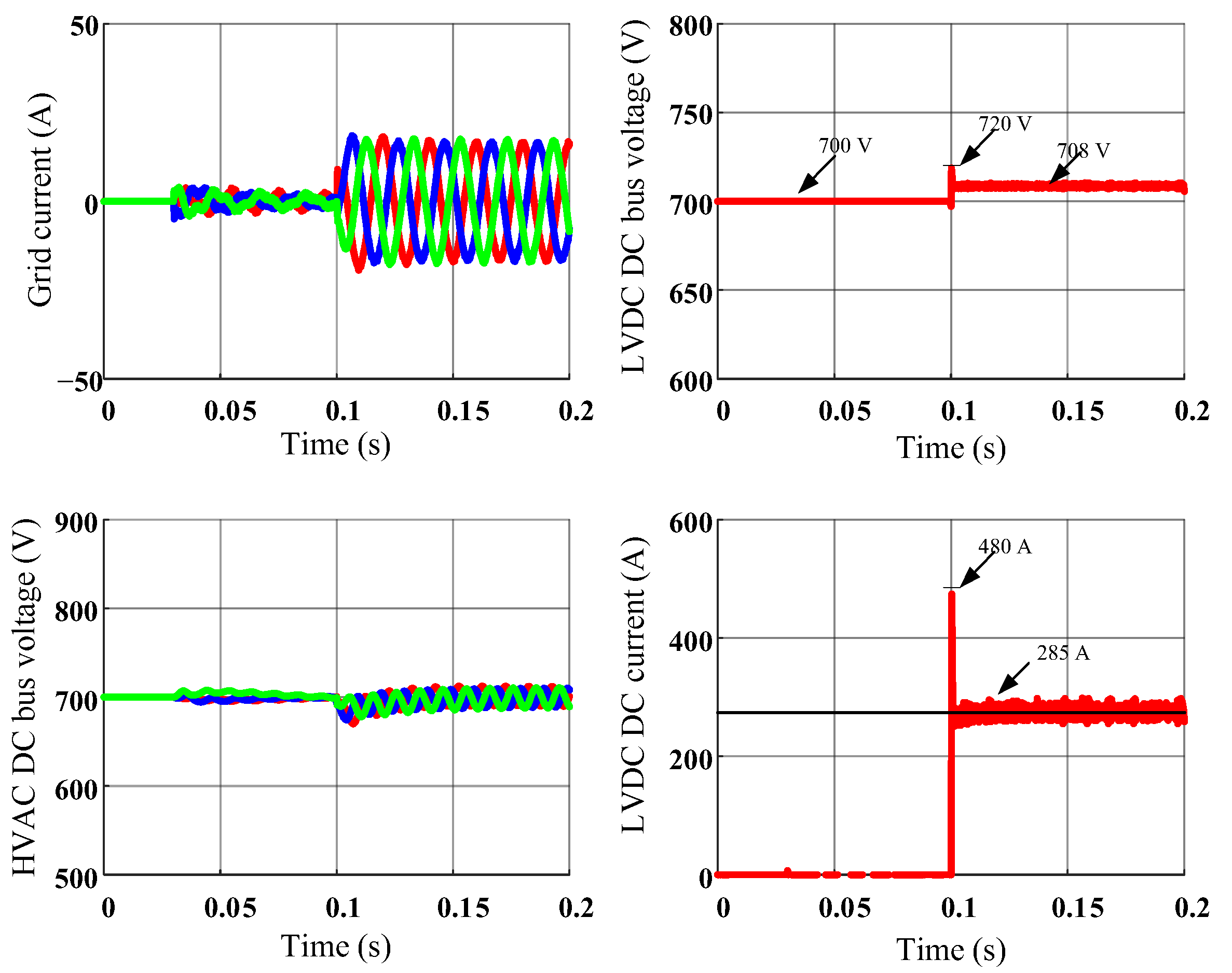
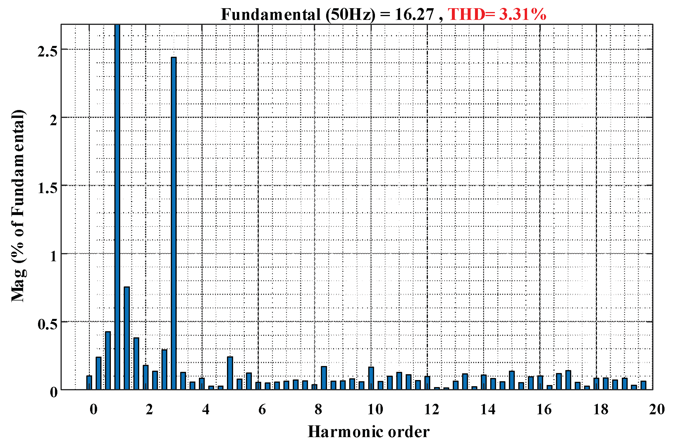
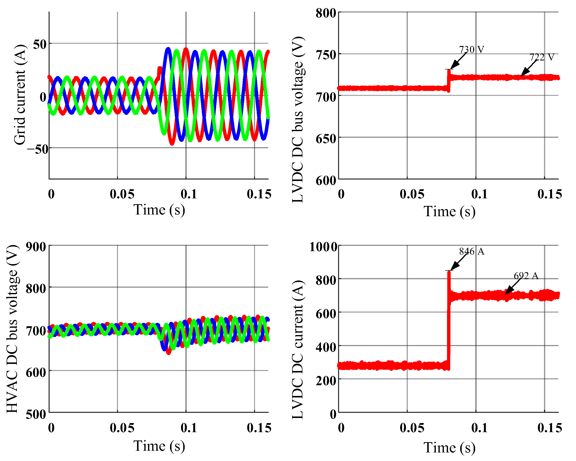
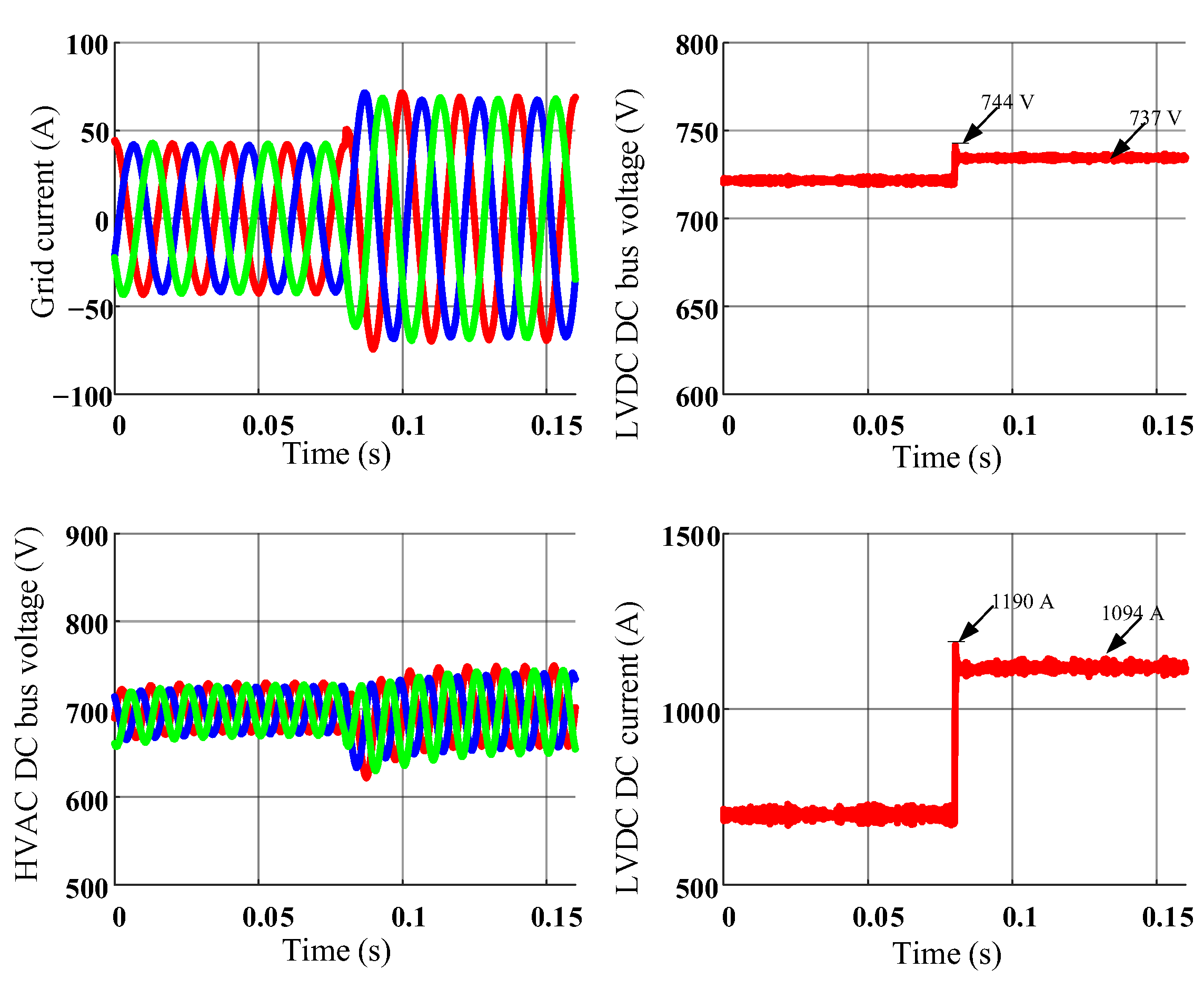
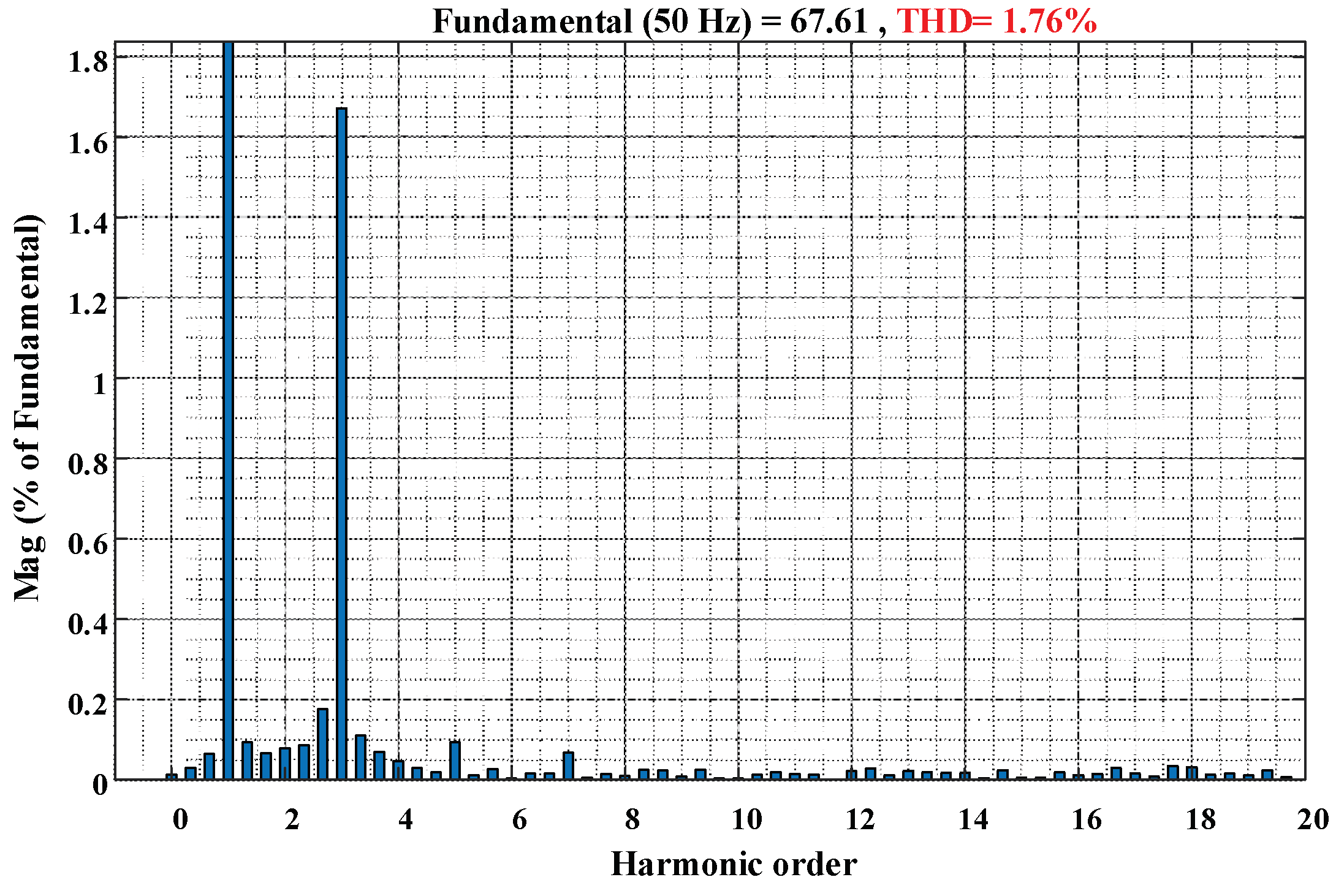
4. Simulation Verification

Based on the PSCAD simulation platform, the simulation model of the energy storage PCS system proposed in this paper is built, the specific parameters are shown in Table 1, and the power step transient process and steady-state process are simulated and analyzed.
Among them, the rated voltage of the power grid is 10 kV and the frequency is 50 Hz. The HVAC part of the energy storage PCS system contains 15 modules in each phase, with a three-phase Y-connection. In each HVAC module, the filter inducement is 16 mH, support capability is 1 mF, HFT capacity is 40 kVA, HFT Leakage inductance is 45 μH and excitation inductance is 3 mH. The LVDC part contains 45 modules, the DC rated voltage is 500~700 V, support capacitance is 1 mF, high-frequency reactance is 7 μF, LVDC output inductance is 10 μF and DC isolation capacitor is 100 μF. The switching frequency is 20 kHz.
Figure 7 shows the simulation results of the grid current, HVDC DC-bus voltage, LVDC DC-bus voltage and LVDC DC current under the condition of battery power step from 0 to 20%. It can be seen that the dynamic response process of the HVAC AC side is less than 20 ms with no overshoot. The peak value of transient overvoltage at the LVDC side is about 720 V and overshoot is about 0.02%, and the peak value of transient overcurrent at the LVDC side is about 480 A and overshoot is about 68.4%, which is within the allowable range. Under the condition of 20% rated power, the output current THDi is 3.31%, as shown in Figure 8.
Figure 9 shows the simulation results of grid current, HVDC DC bus voltage, LVDC DC bus voltage, and LVDC DC current under the condition of battery power step from 20% to 50%. It can be seen that the dynamic response process of the HVAC AC side is less than 20 ms with no overshoot. The peak value of transient overvoltage at the LVDC side is about 730 V and overshoot is about 0.01%, and the peak value of transient overcurrent at the LVDC side is about 846 A and overshoot is about 22.2%, which is within the allowable range. Under the condition of 50% rated power, the output current THDi is 1.31%, as shown in Figure 10.
Figure 11 shows the simulation results of grid current, HVDC DC bus voltage, LVDC DC bus voltage, and LVDC DC current under the condition of battery power step from 50% to 80%. It can be seen that the dynamic response process of the HVAC AC side is less than 20 ms with no overshoot. The peak value of transient overvoltage at the LVDC side is about 744 V and overshoot is about 0.01%, and the peak value of transient overcurrent at the LVDC side is about 1190 A and overshoot is about 0.09%, which is within the allowable range. Under the condition of 50% rated power, the output current THDi is 1.76%, as shown in Figure 12.
Figure 13 shows the simulation results of grid current, HVDC DC bus voltage, LVDC DC bus voltage and LVDC DC current under the condition of battery power step from 80% to 100%. It can be seen that the dynamic response process of the HVAC AC side is less than 20 ms with no overshoot. The peak value of transient overvoltage at the LVDC side is about 750 V and overshoot is about 0.01%, and the peak value of transient overcurrent at the LVDC side is about 1455 A and overshoot is about 0.08%, which is within the allowable range. Under the condition of 50% rated power, the output current THDi is 2.86%, as shown in Figure 14.
In conclusion, under the power step conditions of the PCS, the response of the HVDC port is fast with no overshoot, the voltage overshoot of the LVDC port is small, and the current overshoot is within the allowable range, which has little impact on the energy storage battery. For the output current THDi of the HVDC, it reaches the optimum under medium load, about 1.31%. With the increase in power, THDi increases and reaches 2.86% under rated power, meeting the requirements of grid connection.
In conclusion, under the power step conditions of the PCS, the response of the HVDC port is fast with no overshoot, the LVDC port has low overvoltage, and the current overshoot is within the allowable range, which has little impact on the energy storage battery. The output current THDi of the HVDC reaches the optimum under medium load, about 1.31%. With the increase in power, THDi increases and reaches 2.86% under the rated power, meeting the grid connection requirements.

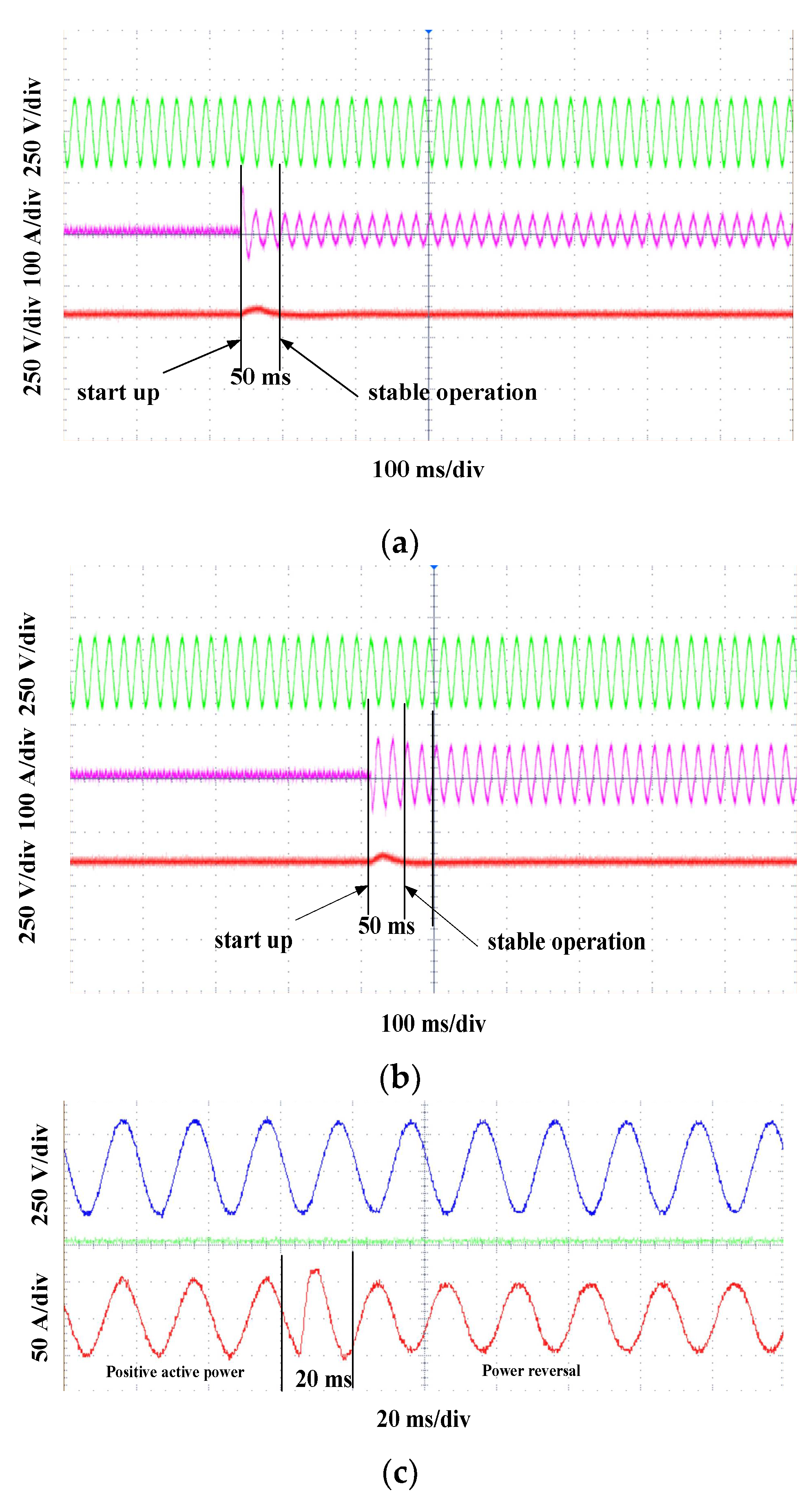
5. Experimental Verification

An experimental prototype of the energy storage PCS with a rated power of 1 MW and rated voltage of 10 kV was built, and the feasibility and effectiveness of the PCS proposed in this paper were verified by comparison and analysis with simulation. The relevant parameters of the prototype are consistent with the simulation parameters, as shown in Table 1.
Traditional silicon (Si) power devices cannot meet developmental needs in selecting power electronic devices. In contrast, silicon carbide (SiC) power devices have lower switching loss, higher operating frequency, smaller passive components and a simpler cooling system design. Thus, they are more conducive to the development trend of high efficiency, miniaturization, lightness and high frequency of power electronic systems [12]. Therefore, the prototype we built adopts a SiC-MOSFET device.
The PCS prototype can be shown as Figure 15, which adopts the SiC-MOSFET switching device with the model of CAS120M12BM2. The source drain voltage of the device is Vds = 1.2 kV, and 15 modules are used for each phase in series for 18 kV, meeting the insulation requirements of the 10 kV voltage level. The rated capacity of each module is 23.8 kW, and the rated through current is about 34 A, with a sufficient through current margin.
First, the power feedback test is carried out for two groups of modules (H-bridge and a DAB), in which the AC side and DC side are connected in parallel. Figure 16a shows the AC voltage, current and DC voltage waveforms of the module under 10 kW power; it can be seen that the stability can be restored within 50 ms, and the DC voltage is slightly overshot. Figure 16b shows waveforms of the module grid under 25 kW power, which shows that the module can recover stability within 50 ms, and the DC voltage is slightly overshot. Figure 16c shows the voltage and current waveforms of the power reversal test. It can be seen that the output current can reach stability within 20 ms without overcurrent. The above tests show that the module can meet the dynamic and steady-state requirements under different working conditions.
Through the power quality analyzer, the HVAC side current waveforms and THD trend of the device prototype are observed. Under light load conditions (10% load rate), Figure 17a shows the three-phase HVAC current waveform with slight distortion. Figure 17b shows the three-phase THDi trend under a steady-state operation within 10 min. It can be seen that THDi is relatively stable, between 2.4% and 2.8%.
Under heavy load conditions (80% load rate), Figure 17c shows the three-phase HVAC current waveforms, which are relatively smooth. Figure 17d shows the three-phase THDi trend under a steady-state operation within 10 min. It can be seen that THDi is relatively stable, between 1.4% and 1.8%.
Figure 18 shows the efficiency curve of PCS under different charging powers. The PCS efficiency can reach more than 98% under a 60% load rate and 98.6% under full load conditions.
The above analysis shows that the test results of the PCS are consistent with the simulation results, which further proves the correctness and feasibility of the proposed new topology of the energy storage converter.
Compared with the conventional topology [22,23], the energy-storage PCS proposed in this paper is isolated by a high-frequency transformer, which can cancel the power frequency transformer, reduce the volume of passive components, improve the power density of equipment, and reduce the insulation costs of energy storage battery. In addition, the engineering prototype adopts SiC-MOSFET switching devices, which improves the rated efficiency of the equipment.

6. Conclusions

In this paper, a high-frequency isolated high-capacity PCS is proposed. The power unit adopts a DAB power module, which effectively suppresses the secondary pulsating current and has higher applicability to the battery; SiC-MOSFET switching devices have been applied, and the maximum efficiency of the equipment can reach 98.6%, with remarkable high-efficiency characteristics. An HVAC and LVDC control strategy based on power decoupling is proposed. Under the power step conditions of the PCS, the response of the HVDC port is fast without overshoot, the voltage overshoot of the LVDC port is small, and the current overshoot is within the allowable range. The output current THDi of the HVDC port is less than 3% under various load rate conditions, meeting the grid connection requirements. The simulation and experimental results show that the high-frequency isolated PCS proposed in this paper is accurate. The engineering application of the equipment in different scenarios, as well as the reliability and costs of the equipment itself, still need to be further improved.

Author Contributions

Conceptualization, N.X. and J.S.; validation, N.X.; writing—original draft preparation N.X. and J.S.; writing—review and editing, N.X. and J.C.; funding acquisition, N.X., H.W. and F.X. All authors have read and agreed to the published version of the manuscript.

Funding

This research was supported by the “Transformational Technologies for Clean Energy and Demonstration” Strategic Priority Research Program of the Chinese Academy of Sciences (Grant No. XDA21000000), the “Key Research and Development Project of Guangdong Province” (No. 2021B0101230004), and Sino-US Green Community DC Microgrid Technology Cooperation Research and Demonstration (2019YFE0120200).

Institutional Review Board Statement

Not applicable.

Informed Consent Statement

Not applicable.

Data Availability Statement

Not applicable.

Conflicts of Interest

The authors declare no conflict of interest.

References

  1. Painuly, J.P. Barriers to renewable energy penetration; a framework for analysis. Renew. Energy 2001, 24, 73–89. [Google Scholar] [CrossRef]
  2. Dunn, B.; Kamath, H.; Tarascon, J.M. Electrical energy storage for the grid: A battery of choices. Science 2011, 334, 928–935. [Google Scholar] [CrossRef] [PubMed] [Green Version]
  3. Wang, F.; Duarte, J.L.; Hendrix, M.A.; Ribeiro, P.F. Modeling and analysis of grid harmonic distortion impact of aggregated DG inverters. IEEE Trans. Power Electron. 2011, 26, 786–797. [Google Scholar] [CrossRef]
  4. Zeng, Z.; Zhao, R.X.; Lv, Z.P.; Ma, L. Impedance reshaping of grid-tied inverters to damp the series and parallel harmonic resonances of photovoltaic systems. Proc. CSEE 2014, 34, 4547–4558. [Google Scholar]
  5. Zhao, B.; Yu, Q.G.; Wang, L.W.; Xiao, Y. Bi-directional extensible converter and its distributed control strategy for battery energy storage Grid-connected system. Proc. CSEE 2011, 31, 244–251. [Google Scholar]
  6. Malinowski, M.; Gopakumar, K.; Rodriguez, J.; Perez, M.A. A survey on cascaded multilevel inverters. IEEE Trans. Ind. Electron. 2010, 57, 2197–2206. [Google Scholar] [CrossRef]
  7. Kawakami, N.; Ota, S.; Kon, H.; Konno, S.; Akagi, H.; Kobayashi, H.; Okada, N. Development of a 500-kW modular multilevel cascade converter for battery energy storage systems. IEEE Trans. Ind. Appl. 2014, 50, 3902–3910. [Google Scholar] [CrossRef]
  8. Ota, J.I.Y.; Sato, T.; Akagi, H. Enhancement of Performance, Availability, and Flexibility of a Battery Energy Storage System Based on a Modular Multilevel Cascaded Converter(MMCC-SSBC). IEEE Trans. Power Electron. 2015, 31, 2791–2799. [Google Scholar] [CrossRef]
  9. Townsend, C.D.; Summers, T.J.; Betz, R.E. Impact of practical issues on the harmonic performance of phase shifted modulation strategies for a cascaded H-bridge StatCom. IEEE Trans. Ind. Electron. 2014, 61, 2655–2664. [Google Scholar] [CrossRef]
  10. Gu, L. A review of single stage high-frequency-isolated three-phase bidirectional AC/DC converter. Proc. CSEE 2021, 41, 7434–7448. [Google Scholar]
  11. Lan, D.; Das, P.; Sahoo, S.K. A high-frequency link matrix rectifier with a pure capacitive output filter in a discontinuous conduction mode. IEEE Trans. Ind. Electron. 2020, 67, 4–15. [Google Scholar] [CrossRef]
  12. Khodabandeh, M.; Afshari, E.; Amirabadi, M. A single-stage soft-switching high-frequency AC-link PV inverter: Design, analysis, and evaluation of Si-based and SiC-based prototypes. IEEE Trans. Power Electron. 2019, 34, 2312–2326. [Google Scholar] [CrossRef]
  13. Rojas, C.A.; Kouro, S.; Perez, M.A.; Echeverria, J. DC-DC MMC for HVDC grid interface of utility-scale photovoltaic conversion systems. IEEE Trans. Ind. Electron. 2018, 65, 352–362. [Google Scholar] [CrossRef]
  14. Sun, K.; Lu, S.L.; Yi, Z.Y.; Cao, G.E.; Wang, Y.B.; Li, Y.D. A Review of High-power High-frequency Transformer Technology for Power Electronic Transformer Applications. Proc. CSEE 2021, 41, 8531–8545. [Google Scholar]
  15. Tan, N.M.L.; Abe, T.; Akagi, H. Design and performance of a bidirectional isolated dc-dc converter for a battery energy storage system. IEEE Trans. Power Electron. 2012, 27, 1237–1248. [Google Scholar] [CrossRef]
  16. Zhao, B.; Song, Q.; Liu, W.; Sun, Y. Overview of dual-active-bridge isolated bi-directional dc-dc converter for high-frequency-link power-conversion system. IEEE Trans. Power Electron. 2014, 29, 4091–4106. [Google Scholar] [CrossRef]
  17. Ma, F.; Kuang, Y.; Wang, Z.; Huang, G.; Kuang, D.; Zhang, C. Multi-Port and -Functional power conditioner and its control strategy with renewable energy access for a railway traction system. Energies 2021, 14, 6146. [Google Scholar] [CrossRef]
  18. Fan, B.; Wang, K.; Zheng, Z.; Xu, L.; Li, Y. Optimized Branch Current Control of Modular Multilevel Matrix Converters Under Branch Fault Conditions. IEEE Trans. Power Electron. 2018, 33, 4578–4583. [Google Scholar] [CrossRef]
  19. Yu, Y.; Konstantinou, G.; Hredzak, B.; Agelidis, V.G. Power balance optimization of cascaded h-bridge multilevel converters for large-scale photovoltaic integration. IEEE Trans. Power Electron. 2016, 31, 1108–1120. [Google Scholar] [CrossRef] [Green Version]
  20. Yang, J.T.; Wu, X.Q.; Li, R.; Ma, K.; Cai, X.; Xu, M.X.; Xu, J. Research on Submodules Voltage-power Self-tracking Control Method for Medium-voltage Direct-linked Photovoltaic Power Generation System. Proc. CSEE 2021, 41, 2815–2824. [Google Scholar]
  21. Xie, N.; Zhao, B.; Zhao, W.; Zhao, Y.; Xie, Z.; Wang, W. High-frequency Isolated and Large Capacity Power Conversion System Based on SiC MOSFET. In 2021 IEEE 5th Conference on Energy Internet and Energy System Integration (EI2); IEEE: Piscataway, NJ, USA, 2021; pp. 3789–3794. [Google Scholar]
  22. Cai, X.; Li, R.; Liu, C. Transformerless High-voltage Power Conversion System for Battery Energy Storage System and the First Demonstration Application in World. Proc. CSEE 2020, 40, 200–211. [Google Scholar]
  23. Tao, Y.B.; Yin, S.; Li, G.J. Design of topology parameters and control technology for direct-hanging energy storage converter. Power Electron. 2022, 56, 35–39. [Google Scholar]
  24. Alam, M.J.E.; Muttaqi, K.M.; Sutanto, D. Effective Utilization of Available PEV Battery Capacity for Mitigation of Solar PV Impact and Grid Support with Integrated V2G Functionality. IEEE Trans. Smart Grid 2017, 7, 1562–1571. [Google Scholar] [CrossRef] [Green Version]
  25. Schrittwieser, L.; Leibl, M.; Kolar, J.W. 99% efficient isolated three-phase matrix-type DAB buck-boost PFC rectifier. IEEE Trans. Power Electron. 2020, 35, 138–157. [Google Scholar] [CrossRef]
  26. Sayed, M.A.; Suzuki, K.; Takeshita, T.; Kitagawa, W. PWM switching technique for three-phase bidirectional grid-tie DC-AC-AC converter with high-frequency isolation. IEEE Trans. Power Electron. 2018, 33, 845–858. [Google Scholar] [CrossRef]
Figure 1. Topology of high-frequency isolated energy storage converter.
Energies 15 05272 g001
Figure 2. DAB topology.
Energies 15 05272 g002
Figure 3. DAB approximate equivalent circuit.
Energies 15 05272 g003
Figure 4. Relationship between transmission power and phase-shift angle.
Energies 15 05272 g004
Figure 5. Average active power control block diagram of HVAC: (a) Three-phase total average active power control block diagram; (b) single-phase average active power control block diagram.
Energies 15 05272 g005
Figure 6. Power control block diagram of LVDC.
Energies 15 05272 g006
Figure 7. Simulation waveform (power from 0 step to 20% rated power).
Energies 15 05272 g007
Figure 8. HVAC grid current THDi (20% of rated power).
Energies 15 05272 g008
Figure 9. Simulation waveform (power from 20% step to 50% rated power).
Energies 15 05272 g009
Figure 10. HVAC grid current THDi (50% of rated power).
Energies 15 05272 g010
Figure 11. Simulation waveform (power from 50% step to 80% rated power).
Energies 15 05272 g011
Figure 12. HVAC grid current THDi (80% of rated power).
Energies 15 05272 g012
Figure 13. Simulation waveform (power from 80% step to 100% rated power).
Energies 15 05272 g013
Figure 14. HVAC grid current THDi (rated power).
Energies 15 05272 g014
Figure 15. PCS prototype.
Energies 15 05272 g015
Figure 16. Double module power cycle test: (a) Power voltage, module current and DC voltage (10 kW); (b) Single-phase average active power control block diagram (25 kW); (c) Power voltage and module current (20 kW).
Energies 15 05272 g016
Figure 17. Current output waveforms and THD trend of PCS: (a) Current output waveforms of PCS (100 kW); (b) THD trend of PCS (100 kW); (c) current output waveforms of PCS (800 kW); (d) THD trend of PCS (800 kW).
Energies 15 05272 g017
Figure 18. Efficiency of PCS under different load rates.
Energies 15 05272 g018
Table 1. Simulation parameters.
ParameterValue
Grid parametersGrid line voltage10 kV
Grid frequency50 Hz
HVACNumber of modules15 per phase, 45 in total
Support capacitance1 mF
HFT parametersCapacity 40 kVA
Leakage inductance 45 μH
Excitation inductance 3 mH
Filter inductance16 mH
LVDCLVDC port voltage range500~700 V
Number of modules45
Support capacitance1 mF
High-frequency reactance7 μH
LVDC output inductance10 μH
DC isolation capacitor100 μF
Switching frequency20 kHz
Publisher’s Note: MDPI stays neutral with regard to jurisdictional claims in published maps and institutional affiliations.

