Abstract
This paper presents the study of air-core transformers for electric vehicles, developing them for medium-power (tens of kWs) converter applications specifically used at a high frequency. Air-core transformers have the advantage of lacking magnetic saturation and iron losses, making them suitable for high-frequency applications. We designed and manufactured a transformer for a determined frequency and inductance value. The design of this passive component aims to both keep the magnetic field inside the transformer and manage the thermal energy efficiently. The electrical, magnetic, and thermal properties are simulated and then verified by experiments with a specific test bench. The transformer reaches high performances for a higher frequency than usual for an equivalent power transfer in automotive applications.
1. Introduction
The extensive use of electrical power in embedded converters requires an increase in the power density with a size reduction of electronic devices. A higher power density is attainable by increasing the frequency of converters for a similar power while maintaining good power efficiency. Wide band-gap transistors, such as Gallium Nitride (GaN) technology, permit a new range of switching frequency for power converters [1,2]. Despite their high electric performances, they induce new issues of high-frequency losses for power conversion, especially in passive components [3]. Depending on the frequency, conduction losses in the conductor and core losses in the transformer are responsible for power losses [4].
We propose to reach a better efficiency for the 7 kW DC/DC by removing the transformer core, consequently reducing the total losses. Limitations due to the saturation of the induction field, eddy effect, and hysteresis losses are therefore avoided [5]. However, air-core transformers are rarely used in power conversion, especially for automotive applications. They are sometimes used as a driver’s flyback converter to generate a quicker response but not for power transmission due to the lack of magnetic field canalization [6,7]. The use of an air-core transformer is usually dedicated to low power application as signal processing because cores can disturb signals by changing harmonics or signal transmissions [8]. Air-core inductors can be used, such as high harmonic filters [9] and current sensors in power applications [10]. In all of the above applications, the power efficiency is not relevant, and the accuracy of the signal through the inductance is the reason for air-core presence. This work focuses on the efficiency, emission, and volume to obtain the best converter possible. We determine a new geometry of air-core transformer fitting with the MHz range of frequency by taking into consideration the power density, the thermal management, and the magnetic radiation around the transformer. This transformer will be used in a Dual Active Bridge (DAB) converter as an isolated DC/DC converter dedicated to a 22 kW bidirectional automotive charger. The DAB topology allows a constant switching frequency and a ZVS soft-switching technique. We focus in particular on a 7 kW DC/DC converter, which leads to 22 kW with three blocks. We also present a simulation study on the electrical and magnetic key parameters for the new geometry of the transformer. To verify the simulation result, a 3D-printed plastic support was designed, and a prototype was realized to validate the thermal behavior. A dedicated test bench was set up to reach the nominal current in the transformer using only two switches in zero-voltage switching conditions. Finally, thermal management simulation results were evaluated for creating a final support fitting with our application. Several tests were performed using an impedance analyzer, closed field test bench, and thermal camera for confirming the simulation results.
2. Design of the Proposed Transformer
2.1. Magnetic Field Canalization
The huge advantage of an air-core magnetic component is the absence of a core. The usual geometry of air-core inductance is toroidal in order to limit the magnetic field inside the component. The superposition theorem is used with a revolution’s symmetry as in [11]. Figure 1a shows qualitatively the development of one coil passing to a toroidal inductance with FEMM simulations. This geometry is insufficient for power applications because of thermal issues. The symmetrical structure allows the fringing effect to be disregarded [12]. However, the transformer realization is difficult due to the use of sewing techniques. The superposition theorem leads first to magnetic field canalization and then to the maximization of the inductance value.
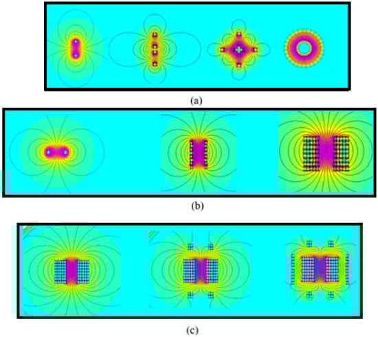
Figure 1.
(a) Tore elaboration; (b) Solenoid elaboration; (c) Magnetic field canalization of a solenoid.
Figure 1b illustrates the transformation from one coil to one solenoid. This transformation improves the magnetic field concentration without canalizing it. The additional winding around the transformer improves the magnetic field canalization and the necessary inductance value, as presented in Figure 1c. The result leads to a reduction of the total magnetic field out of the transformer and the transformer’s inductance. Figure 2 illustrates the canalization field with the positive induction spires at the center and the negative induction spires around, differentiated by the current orientation in opposition. We propose to arrange the geometry by keeping a high inductance value with a weak magnetic field around the transformer. The transformer characteristics are described below in Table 1 for 1500 kHz, which is the switching frequency of our converter application. Further analyses are presented in [13]. Table 1 globally shows a drastic limitation of the magnetic emission, considering that the probe is set at 2 cm from the conductor for a 10% reduction of the inductance value by additional conductors. However, the transformer volume is increased due to its higher number of turns necessary for obtaining an identical inductance value. The quality factor [14] is not considered in this work, although this coefficient is dependent on the frequency, and the goal of this work is to increase the induction retainability.
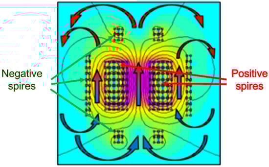
Figure 2.
Natural air flux possible in the transformer with induction field canalization in background.

Table 1.
Inductance result of finite element method simulation.
In the next calculations, we established by simulations and experiments a first approximation of the desired value by using Formula (1) applied for a classical solenoid minus 10% [15]. represents the inductance value, the vacuum permeability, N the number of turns, and the internal diameter of the inductance.
We can balance the result with Formula (2) of the square section toroidal inductance [16] to determine the best dimensions for a fixed inductance value of 15.22 µH. The results are in Table 2, with and , respectively, the internal and external radius.
Table 2.
Comparison between tore and canalized solenoid.
In comparison with the same inductance value, both a 2.6-fold lower volume and 24% less wire length is obtained. Even if the magnetic emission is 3.2 times higher, this value is considered too low to create disturbances in the system regarding the value of 20 µT considered.
Moreover, in comparison with a tore, the solenoid geometry is easier to realize, and the air inside the transformer is free of convection, allowing a natural or forced convection to perform a better cooldown as shown in Figure 2.
2.2. Conduction Losses
The transformer losses consist of winding DC loss, winding AC loss, and core loss. The latter two are the worst considering the high-frequency application and are increased proportionally by the frequency as we can observe in Formulas (3) and (4), providing a classical transformer design [17]. In air-core magnetic devices, those losses are avoided, even if AC winding losses composed of proximity effect and skin effect are still present [18]. However, these effects are increased with the square root of the frequency, as described in Formula (5), and impact the global resistance by modifying the current circulation in the wires as mentioned by Formula (6).
In these formulas, is the frequency, the resistivity, the magnetic field, the magnetic permeability, and the DC resistance. and are geometrical-dependant parameters. and are the hysteresis coefficient, the weight of the core, the skin effect coefficient, and the effective current. In (6), represents the number of alternating windings with an identical current direction side by side. This winding configuration drastically reduces the proximity effect. The magnetic field with this structural compensation and its coupling coefficient is also improved. The current orientation in the secondary winding is therefore opposed to those of the primary winding, resulting in a negligible proximity effect [19]. Finally, the strongest factor of loss is due to the skin effect.
Furthermore, Litz wire was selected because of its external magnetic field independence and its handling facility [20].
2.3. Model and Simulation
To model the transformer and to evaluate its magnetic emission, FEMM simulations were realized. A numerical approach was used to determine the best position of the windings. The study was simplified by taking advantage of the symmetric revolution and symmetric surface in the center of the transformer. Simulations of a quarter of the transformer section were therefore realized on a 2D surface.
The model is accurate enough compared to a usual transformer because of the nonlinear hysteresis presence due to the magnetic core absence. It corresponds simply to the linear properties of the Biot and Savart equation with the constant permeability of the magnetic circuit as in Equation (7). The magnetic contribution depends on the crossing current , the elemental distance , and the distance between the chosen coordinates and the turn .
The value of the magnetic component is determined at each point of the space in (8). For a dedicated coordinate , the turn induces a magnetic excitation . After summing up the magnetic contributions of all turns, we can integrate them in (9).
In Figure 3, the red points represent the primary windings, while the blue points represent the secondary windings. Indeed, it is advised to alternate as represented the primary and secondary windings in order to limit the internal induction increases and losses related due, for example, to the proximity effect. The results in the open-circuit condition, with the secondary in open circuit, are plotted in Figure 3. The magnetic field arrows stay inside the windings, and the magnetic field is canalized.
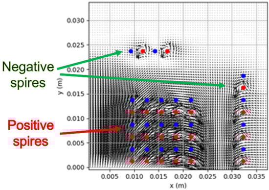
Figure 3.
Magnetic field model on python.
3. Electromagnetic Calculation
This section may be divided by subheadings and provides a concise and accurate description of the experimental results, their interpretation, and the experimental conclusions.
3.1. Electrical Simulation
By adding the magnetic field in each point, the magnetic field crossing one turn induces a specific magnetic flux as described in Equation (11) where is the axis component of the magnetic field. The value of the total flux is therefore determined in addition to the self-inductance value of the transformer via Equation (12). The natural inductance of the copper wire was added to the equation to improve the accuracy of the calculation with as the copper length.
To determine the value of the equivalent resistance transformer, we assumed that the main losses are induced by skin effect and proximity effects between the wire strands, and we neglected the proximity losses between turns because of the interlacing winding between primary and secondary. The properties of the Litz wire are characterized by an impedance analyzer, and we obtained a metric resistance of 46 mΩ/m at 1.5 MHz. By simulation, we obtained the length of the windings and an equivalent resistance
The best geometry simulation of our transformer was the result of the geometrical parameter sweeping optimization, using the inductance value as a condition and the magnetic field emission reduction as parameters for the variable configuration, presented in Figure 4. The geometrical problem is constituted of 10 variables, 4 decimal distance variables, and 6 integer variables of the number of turns.
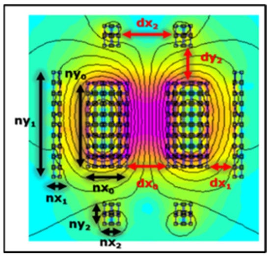
Figure 4.
Parameter configurations with canalization of the induction field in background.
A transformer matching with a self-inductance of 20 µH was obtained with the following properties (Table 3). It allows the comparison between electrical simulation and experimental results, performed by the impedance analyzer.
Table 3.
Transformer simulation result.
As observed, the experimental results match perfectly with the simulation. We note that as the proximity effect losses due to the handle realization are considered, the effective resistance is higher than the simulated resistance. This difference could be reduced by realizing industrially a transformer, for a higher accuracy of winding configurations. The self-inductance is quite similar, although the simulation does not include the wire’s length for connecting the transformer at the converter, which logically increases the overall inductance and resistance. However, the leakage inductance measured smaller than expected. This result can be physically explained. In the simulation, inside the transformer, a 2.5 mm space separated each wire, whereas for handing simplification, the distance was experimentally only 2.3 mm. The latter is therefore closer to the primary winding, resulting in a smaller leakage inductance measure.
3.2. Test Bench
For the magnetic and thermal study, the transformer was evaluated in nominal electrical conditions, such as 450 V and 30 A at 1500 kHz. Indeed, as viewed in Formula (5), losses depend on current and frequency as well as on the magnetic field as written in (7). A specific test bench ensures soft switching at a high frequency, and a high current was designed. It consists of only one inverter branch instead of a full converter. The following RLC series configuration is proposed in Figure 5. Its associated command is developed as follows: an inverter branch provides a square signal from 0 to U between the middle point and the ground. This signal is composed of the DC value Um and an alternative square signal Ualt.
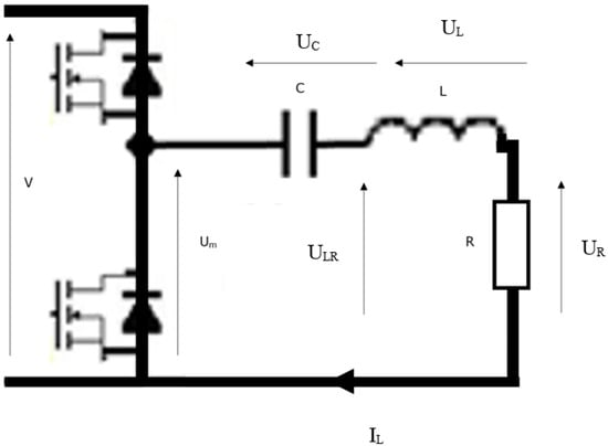
Figure 5.
RLC series test bench.
The voltage equations are in (13).
For the DC study, we assumed that the transient components are zero. The simplification is therefore written in (14).
The DC signal is entirely consumed by the capacitor and the equivalent capacitors according to (15). The square signal Ualt through LR is the only component in the transformer in a short-circuit configuration.
As the frequency is high enough, we neglected the resistance contribution. This condition can be represented by Equation (18).
The current in the transformer has a similar behavior to the integration of according to (19). The peak current value becomes also easier to calculate because of its triangle form and is expressed in (20).
3.3. Electrical Measurements
Thanks to this process, a natural 29 A triangular form of switching of the current was observed as shown in Figure 6. According to Equation (20), this current corresponds to an RMS current of 15.5 A, which is the appropriate current for a 7 kW transfer power when 450 V is applied to the converter.
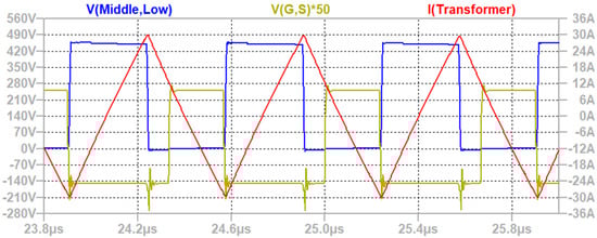
Figure 6.
Simulation results of the test bench; in red the current; in blue Vds; and in yellow Vgs.
The test bench results in Figure 7 confirm the precedent simulations, calculations, and soft-switching operations. The 15.61 arms (red) for a square voltage signal of 450 V were obtained (yellow). The Vgs signal (blue) shows the soft-switching mode when the simultaneous current is changing of signs.
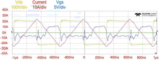
Figure 7.
Test on the RLC configuration.
The benefit of the full converter in terms of power density, through the volume and weight, was developed in a Dual Active Bridge (DAB) application [21]. The comparison with an equivalent power transformer [22] switching at 500 kHz instead of 1500 kHz proves the power density gain for the embedded application, even if a further analysis, such as for reliability, has to be carried out. In addition, in this study, we only considered the transformer, although the whole converter, with, for example, electromagnetic compatibility (EMC) filters, has to be studied. Finally, the transformer comparison is not totally relevant because of the strong difference of behavior due to the high switching frequency, leading to limits for a ferrite core, such as the core magnetic saturation and thermal management due to iron losses.
3.4. Magnetic Simulation
In Section 3.1, the magnetic emission is plotted to validate the best arrangement of windings. The magnetic field emission is a huge issue for the air-core transformer to avoid EM problems in other parts of the converter. A magnetic study was firstly performed by simulation by applying Biot and Savart’s laws and then by experiment to verify the magnetic field canalization and the low value of magnetic emission around the transformer. Two simulations were proposed, considering only one quarter of the transformer due to symmetry: one in open-circuit configuration to see the magnetic field inside the transformer and the other in short-circuit configuration to observe the magnetic emission at the nominal point. A reference line at the transformer center (blue) and a line above (orange) at the 5 mm of the transformer extremity were plotted to discuss the magnetic canalization, such as in Figure 8 and Figure 9.
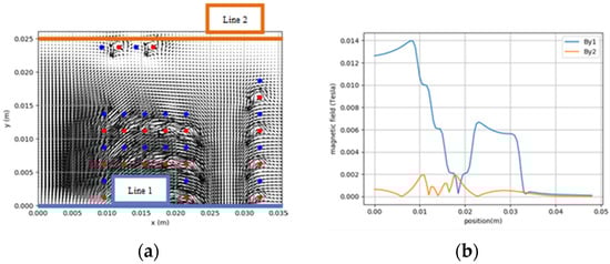
Figure 8.
Open-circuit test: (a) Studied lines of magnetic field; (b) Magnetic field.
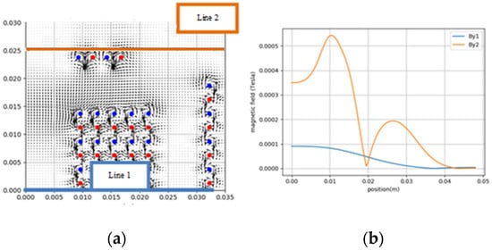
Figure 9.
Short circuit test: (a) Studied lines of magnetic field; (b) Magnetic field.
The magnetic field around the transformer reaches in simulation 560 µT at 5 mm of distance above the Device Under Test (DUT). To compare with the test bench, the transformer was carried on a wooden structure, and a mapping of the magnetic field was realized with a near-field measurement platform as in Figure 10.
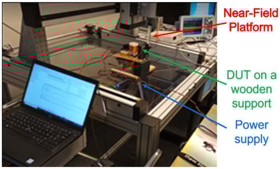
Figure 10.
DUT under test with the closed field test bench.
The simulation and probe mapping start at 1 cm of the transformer’s winding because of the probe’s dimension. The test bench was set up as explained in Section 3.2, and the emission measurement system was performed by a robot as in Figure 11.
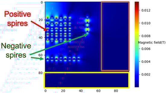
Figure 11.
Transformer magnetic field mapping and test surfaces with in red, the vertical characterization and in yellow the horizontal characterization.
As it is impossible to measure the magnetic field with a probe inside the transformer due to high magnetic field values, the mapping was separated into two rectangles as in Figure 10. The simulation results were fitted using the symmetry properties to match with the coordinates of experimental tests [23].
The simulation and experimental results seem to have similar hot points as shown in Figure 12a,b and were obtained by using the previous test bench. We confirm in both cases that the magnetic field emission was measured under 200 µT at 1 m, which is the limit fixed by the ICNIRP for automotive applications [24]. The converter should not have any EMC issues in terms of emission compatibility due to its low magnetic emission value [25]. The brown and yellow squares are reminders of the probe measurement areas according to Figure 10.
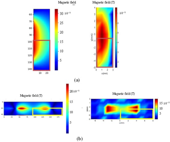
Figure 12.
Comparison of simulation and test: (a) On the yellow surface measurement with symmetrical mapping added; (b) on the brown surface measurement with symmetrical mapping added.
4. Thermal Design
4.1. Support Material Determination
To realize the transformer, a nonmagnetic support had to be designed with a material able to withstand high temperatures. Because of prototyping issues, the quickest and easiest way to design this support was with a 3D printer. A comparison among 3D materials is displayed in Table 4 [26]. As the literature is poor on coreless power transformers, comparisons are difficult, but after several prototypes, a deep study is proposed here.
Table 4.
Comparison among different printing materials.
The value of glass transition temperature is the most important parameter to select the printing material because it determines the thermal limit of the transformer. In addition, the thermal conduction must be the highest as possible. The “Impact Resistance” parameter is also important for manipulation issues because manual process requires robustness of the support to not fall apart. A minimal hardness is also required to limit winding deformation.
PC material has the highest glass transition temperature. Moreover, its high thermal conduction is a good point for cooling the transformer, and its consistency is enough for keeping its shape when we manipulated or ventilated the transformer. Nevertheless, the low-impact resistance of the PC material requires precaution to avoid any fragility during the realization process. A special water-soluble support was therefore used to fit the high printing temperature of PC and to ensure accurate printing without any manipulations. Finally, the hand-winding process was carefully performed because the Litz wire helped to maintain a more homogeneous component.
4.2. Natural Convection
The honeycomb geometry is a good balance between thermal evacuation and solidity for natural convection [27,28].
The support is composed of two pieces: Part A corresponds to the central and the top/down windings, such as in Figure 13a, and part B corresponds to the external winding as in Figure 13b. Part B finally fits around part A as in Figure 13c.
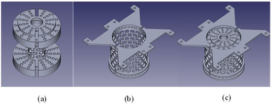
Figure 13.
Model of transformer’s support: (a) Inside part A; (b) Outside part B; (c) Addition of both for total transformer support before winding.
For determining the temperature for heat evacuation, we started by calculating the power losses. As shown in Table 3, a resistance value of 248 mΩ at ambient temperature was obtained for the transformer windings, resulting in a current of 15.5 A in 56 W to dissipate. A thermal simulation of the transformer was generated on Ansys software for a constant power of 56 W to dissipate. That means that we considered the resistance value independent of the temperature and that the dissipated power is equally distributed along the transformer winding. We considered in addition to this model a Kapton insulation of the Litz wire and thermal properties of the PC support. If the temperature is considered higher or if the distribution is not perfectly distributed, the losses will be further increased.
The first simulation was realized in a natural convection configuration, with a temperature conductor limit, fixed by the manufacturer at 180 °C, and by the PC support at 110 °C. The simulation results are shown in Figure 14a especially for the conductor and in Figure 15b for the plastic support. In natural convection, there is no additional structure, and the transformer’s volume can be considered as final. Otherwise, we would need to add a specific heatsink, for example, for the heat evacuation.
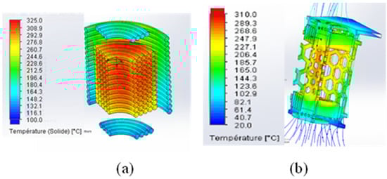
Figure 14.
Thermal simulation of the air-core transformer: (a) Conductor focus; (b) Support focus.
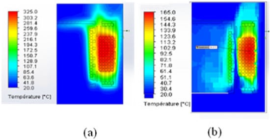
Figure 15.
Thermal simulation of the air-core transformer: (a) Natural convection; (b) Forced convection.
Both conductor and support exceed their limit. Indeed, they reached 325 °C and 310 °C, respectively, in a steady state. Natural convection and forced convection are compared and presented in Figure 15.
The conductor temperature varies from 325 °C to 162 °C, which is presently tolerated. However, the PC temperature is more susceptible and still too high at 142 °C. The next part exposes the different possibilities explored to decrease the transformer’s temperature to a steady-state configuration.
4.3. Air-Forced Convection
Three thermal issues for cooling improvement are proposed:
4.3.1. Change Material
In our case, PC is the best material choice for 3D printing, and its study requires several prototypes. The first improvement technique will not be explored further. The study will finish with the presentation of two other improvement possibilities.
4.3.2. Change the Support Geometry
Four main modifications are proposed, as shown in Figure 16:
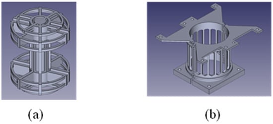
Figure 16.
New support geometry for air-forced convection: (a) Inside part; (b) Outside part.
- The honeycomb configuration is replaced by long vertical corridors increasing the exchange surface in the direction of the fan.
- The above and below parts are the airiest as possible.
- A cylindrical part is added in the middle of the inside hole to force ventilated air to be in contact with the hot surfaces.
- A base is fixed to the fan and confines the air inside the transformer where the temperature is the highest.
4.3.3. Add Spaced Layers
This new support was simulated with classical winding and a space of 0.5 mm between each layer of the central part, instead of being in contact. This third improvement modification also reduces the leakage inductance and improves the self-inductance of the transformer [15]. This configuration was not realized in the first version because the layer’s space was not considered as a parameter of study for our transformer design. The two simulations resulting from the new support are presented in Figure 17.
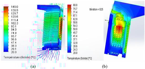
Figure 17.
Thermal simulation of the air-forced convection configuration: (a) Classical winding; (b) Spaced layer of 0.5 mm.
The new geometry decreases the temperature only from 162 °C to 148 °C in the conductor, which is not enough for the PC support. The space between layers provides better thermal performances and decreases the temperature in the windings to 80 °C. The PC stays under 80 °C for a limit fixed at 110 °C.
The first geometry with natural convection and the final geometry with the new support with spaced windings are presented in Figure 18.
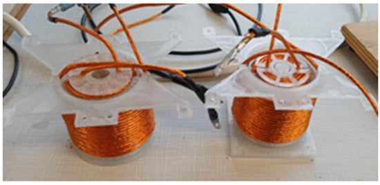
Figure 18.
Air-core transformer: Left: Natural convection; Right: Air-forced convection.
The temperature was then evaluated experimentally with a current of 15.5 A in the transformer at a frequency of 1.5 MHz. The natural convection geometry can withstand the requirements.
The thermal simulation and experiments validate the transformer’s thermal property fitting with a 7 kW power transfer (Figure 19). Measurements by thermal camera show a temperature of 47.5 °C matching the simulation. Even if the accuracy of the thermal camera is debatable, an elevation of temperature is observed, leading to the transformer being able to work properly in a steady state.
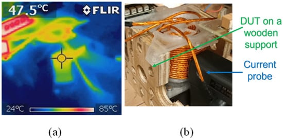
Figure 19.
Thermal results: (a) Thermal camera picture; (b) Reference image.
5. Conclusions
This article proposes a new geometry of air-core transformers for medium power application as embedded in an electrical vehicle reaching high performances. This geometry opens a new range of frequency for DC/DC converters in automotive applications, fitting with the wide bandgap transistor abilities for a high frequency and a high power density. In this study, electrical, magnetic, and thermal parameters are analyzed by simulation and are experimentally tested. We succeeded indeed in making one with a specific value of self-inductance and a high coupling coefficient. Comparisons were carried out among simulations and measurements, and they validate the device. Several ideas are proposed for improving cooling and to keep the magnetic emission below the norm, as well as an optimal design to facilitate the thermal management in a steady state. The result ensures a possible operation of the transformer at 1.5 MHz and a 7 kW power conversion in Dual Active Bridge operation. A full prototype of the converter is still in development but could drastically improve the power density.
Author Contributions
Investigation, V.R. and T.P.; Resources, J.S.; Supervision, D.S. All authors have read and agreed to the published version of the manuscript.
Funding
This research received no external funding.
Conflicts of Interest
The authors declare no conflict of interest.
References
- Jafari, A.; Nikoo, M.S.; Perera, N.; Yildirim, H.K.; Karakaya, F.; Soleimanzadeh, R.; Matioli, E. Comparison of Wide-band-gap Technologies for Soft-Switching Losses at High Frequencies. IEEE Trans. Power Electron. 2020, 35, 12595–12600. [Google Scholar] [CrossRef]
- Ribeiro, K.; Sadarnac, D.; Karimi, C.; Phulpin, T.; Bendani, L. A Bidirectional Three-port Current-fed LC Parallel Resonant Converter. In Proceedings of the 13th IEEE International Conference on Power Electronics and Drive Systems (PEDS 2019), Toulouse, France, 9–12 July 2019. [Google Scholar] [CrossRef]
- Sobrayen, L.; Dehem, P.; Karimi, C.; Phulpin, T.; Sadarnac, D. Modeling and ZVS Constraints of the Hybrid LLC Resonant Converter for MHz Level Operation. In Proceedings of the ECCE, Virtual, Vancouver, BC, Canada, 10–14 October 2021. [Google Scholar]
- Kabbara, W.; Bensetti, M.; Phulpin, T.; Caillierez, A.; Loudot, S.; Sadarnac, D. A Control Strategy to Avoid Drop and Inrush Currents during Transient Phases in a Multi-Transmitters DIPT System. Energies 2022, 15, 2911. [Google Scholar] [CrossRef]
- Nigam, M.; Sullivan, C.R. Multi-layer folded high-frequency toroidal inductor winding. In Proceedings of the IEEE Applied Power Electronics Conference, Austin, TX, USA, 24–28 February 2008; pp. 682–688. [Google Scholar]
- Yildirim, H.K.; Karakaya, F.; Soleimanzadeh, R.; Matioli, E. Design and analysis of different structures of a coreless planar transformer for a flyback converter. In Proceedings of the International Symposium on Power Electronics Power Electronics, Electrical Drives, Automation and Motion, Sorrento, Italy, 20–22 June 2012; pp. 827–831. [Google Scholar] [CrossRef]
- Hui, S.Y.R.; Chung, H.; Tang, S.C. Coreless PCB-based transformers for Power MOSFET/IGBT Gate Drive Circuits. In Proceedings of the PESC97, Record 28th Annual IEEE Power Electronics Specialists Conference, Formerly Power Conditioning Specialists Conference 1970-71, Power Processing and Electronic Specialists Conference 1972, St. Louis, MO, USA, 27 June 1997; Volume 2, pp. 1171–1176. [Google Scholar] [CrossRef]
- Yunas, J.; Yeop, B.; Azrul, M.; Hamzah, A.; Bais, B. Si Monolithic Planar Coreless Inductors for High Frequency Signal Transmission. In Proceedings of the 2013 IEEE International RF and Microwave Conference (RFM), Penang, Malaysia, 9–11 December 2013; pp. 47–50. [Google Scholar] [CrossRef]
- Reggiani, U.; Grandi, G.; Sancineto, G.; Serra, G. Comparison Between Air-Core and Laminated Iron-Core Inductors in Filtering Applications for Switching Converter. In Proceedings of the 7th IEEE International Power Electronics Congress. Technical Proceedings. CIEP 2000 (Cat. No.00TH8529), Acapulco, Mexico, 15–19 October 2000; pp. 9–14. [Google Scholar] [CrossRef]
- Ma, X.; Guo, Y.; Chen, X.; Xiang, Y.; Chen, K.-L. Impact of Coreless Current Transformer Position on Current Measurement. IEEE Trans. Instrum. Meas. 2019, 68, 3801–3809. [Google Scholar] [CrossRef]
- Murgatroyd, P.N. The Optimal Form for Coreless Inductors. IEEE Trans. Magn. 1989, 25, 2670–2677. [Google Scholar] [CrossRef]
- Hsuan, L.; Jiann-Fuh, C. Design process of high-frequency inductor with multiple air-gaps in the dimensional limitation. IET Power Electron. 2021, 16–33. [Google Scholar] [CrossRef]
- Rigot, V.; Phulpin, T.; Sadarnac, D.; Sakly, J. A new design of an air core transformer for Electric Vehicle On-Board Charger. In Proceedings of the 2020 22nd European Conference on Power Electronics and Applications (EPE’20 ECCE Europe), Lyon, France, 7–11 September 2020; pp. 1–9. [Google Scholar]
- Zhang, H.-B.; Cai, M.; He, X.-Y.; Chen, G.-H.; Wu, H.-J. A high self-resonant and quality factor transformer using novel geometry for silicon based RFICs. In Proceedings of the 2013 IEEE International Conference of Electron Devices and Solid-State Circuits, Hong Kong, China, 3–5 June 2013. [Google Scholar]
- Yu, D.; Han, K.S. Self-Inductance of Air-Core Circular Coils with Rectangular Cross Section. IEEE Trans. Magn. 1987, 23, 3916–3921. [Google Scholar] [CrossRef]
- Sadarnac, D. Du Composant Magnétique à L’électronique de Puissance—Analyse Modélisation Conception Dimensionnement des Transformateurs Inductances Convertisseurs—Cours et Exercices Corrigés; Ellipses: Paris, France, 2014. [Google Scholar]
- Vaisambhayana, S.; Dincan, C.; Shuyu, C.; Tripathi, A.; Haonan, T.; Karthikeya, B.R. State of Art survey for design of Medium Frequency High Power Transformer. In Proceedings of the 2016 Asian Conference on Energy, Power and Transportation Electrification (ACEPT), Singapore, 25–27 October 2016. [Google Scholar]
- Dowell, P.L. Effects of eddy currents in transformer windings. Proc. Inst. Electr. Eng. 1966, 113, 1387–1394. [Google Scholar] [CrossRef]
- Meyer, P.; Perriard, Y. Skin and Proximity Effects for Coreless Transformers. In Proceedings of the 2011 International Conference on Electrical Machines and Systems, Beijing, China, 20–23 August 2011; pp. 1–5. [Google Scholar] [CrossRef]
- Wojda, R.P.; Kazimierczuk, M.K. Winding Resistance and Power Loss of Inductors with Litz and Solid-Round Wires. In Proceedings of the 2016 IEEE International Power Electronics and Motion Control Conference (PEMC), Varna, Bulgaria, 25–28 September 2016; pp. 860–865. [Google Scholar] [CrossRef]
- Rigot, V.; Phulpin, T.; Sakly, J.; Sadarnac, D. An Automotive High-Frequency Coreless Transformer of 11kw Dual Active Bridge Converter. In Proceedings of the PCIM2022, Nuremberg, Germany, 10–12 May 2022. [Google Scholar]
- Taurou, E.; Sadarnac, D.; Karimi, C.; Doffin, H. Design of a transformer for high power density charger—Electric vehicles application. In Proceedings of the 2017 19th European Conference on Power Electronics and Applications (EPE’17 ECCE Europe), Warsaw, Poland, 11–14 September 2017; pp. 1–10. [Google Scholar] [CrossRef]
- Pei, Y.; Le Bihan, Y.; Bensetti, M.; Pichon, L. Comparison of Coupling Coils for Static Inductive Power-Transfer Systems Taking into Account Sources of Uncertainty. Sustainability 2021, 13, 6324. [Google Scholar] [CrossRef]
- Lin, J.; Saunders, R.; Schulmeister, K.; Söderberg, P.; Stuck, B.; Swerdlow, A.; Taki, M.; Veyret, B.; Ziegelberger, G.; Repacholi, M.H. ICNIRP guidelines for limiting exposure to time-varying electric and magnetic fields (1 Hz TO 100 kHz). Health Phys. 2010, 99, 818–836. [Google Scholar] [CrossRef]
- International Commission on Non-Ionizing Radiation Protection. Guidelines for limiting exposure to electromagnetic fields (100 khz to 300 ghz). Health Phys. 2020, 118, 483–524. [Google Scholar] [CrossRef] [PubMed]
- Available online: https://ultimaker.com (accessed on 9 October 2021).
- Hexeb™ “Honeycomb Attributes and Properties” Hexcel Composites 2010-06-01. Available online: https://www.hexcel.com/Products/Honeycomb/ (accessed on 17 July 2022).
- Oftadeh, R.; Haghpanah, B.; Vella, D.; Boudaoud, A.; Vaziri, A. Optimal Fractal-like Hierarchical Honeycombs. Phys. Rev. Lett. 2014, 113, 104301. [Google Scholar] [CrossRef] [PubMed] [Green Version]
Publisher’s Note: MDPI stays neutral with regard to jurisdictional claims in published maps and institutional affiliations. |
© 2022 by the authors. Licensee MDPI, Basel, Switzerland. This article is an open access article distributed under the terms and conditions of the Creative Commons Attribution (CC BY) license (https://creativecommons.org/licenses/by/4.0/).