Article

Guidelines on Composite Flexible Risers: Monitoring Techniques and Design Approaches

1
Department of Engineering, Lancaster University, Bailrigg, Lancaster LA1 4YR, UK
2
Standards Organisation of Nigeria (SON), 52 Lome Crescent, Wuse Zone 7, Abuja 900287, Nigeria
3
School of Civil and Mechanical Engineering, Curtin University, Bentley, WA 6102, Australia
4
Department of Civil Engineering, Universiti Teknologi PETRONAS, Seri Iskander 32610, Malaysia
5
School of Civil and Architectural Engineering, Shandong University of Technology, Zibo 255000, China
6
College of Safety and Ocean Engineering, China University of Petroleum—Beijing, Beijing 102249, China
*
Author to whom correspondence should be addressed.
Energies 2022, 15(14), 4982; https://doi.org/10.3390/en15144982
Submission received: 5 June 2022 / Revised: 2 July 2022 / Accepted: 4 July 2022 / Published: 7 July 2022

Abstract

:
The increasing energy demand has led to more explorations in the oil and gas industry. To achieve this, marine risers and pipelines are used to convey fluid and other resources to meet the increasing demand. In recent years, hybrid flexible composite risers have become more adaptable. Flexible risers have already proven to be a popular riser solution for various floating production systems in shallow to deepwater in many parts of the world due to their good dynamic behaviour and dependability. The hybrid flexible composite riser is made up of numerous layers of plastics, flexible pipes, composites, and steel. Some innovative monitoring methods, such as Fiber Optics Bragg Gratings (FBG), are based on a clamped composite structure with embedded optical fibre. This study presents characteristics of the monitoring techniques of composite flexible riser technology. The advantages of the monitoring techniques include aiding composite riser measurements, recording data from riser deformation, improving integrity assurance, and dependability of design from stable readings. It also proposes some design approaches as guidelines that are advised, with some policy implications.

1. Introduction

The increasing energy demand has led to more explorations in the oil and gas industry. To achieve this, marine risers and pipelines are used to convey fluid and other resources to meet the increasing demand. In addition, offshore platforms are designed to have structural components and conduits for extracting oil and gas products to provide energy [1,2,3]. However, the structural strength of aeronautical structures, subsea pipelines\cables, and marine risers is subject to certain limits, which also affect their service life and useability [4,5,6,7]. Conversely, an engineering challenge faced by pipe designers includes sustainable design methods, safe operating procedures, and better monitoring techniques [8,9,10,11]. The safety and protection of SURF (subsea cables, umbilicals, risers, and flowlines) systems have increased demand in the industry [12,13,14,15,16,17]. Aside from protection, material choice is also important for long service and for preventing any structural failure. Hence, the reliability of the engineering material is important and requires some monitoring. However, the strengths of engineering materials, such as steel and composites, differ.
Steel has long been utilised in the oil and gas sector throughout the hydrocarbon value chain, from wells and rig equipment to onshore pipelines, marine risers, subsea cables, storage tanks, and refineries [18,19,20,21,22]. Composites, on the other hand, are gaining popularity due to the multiple advantages they provide over traditional building materials, such as steel and aluminium [23,24,25,26,27,28]. The use of composites decreases the total weight of the structure, improves corrosion resistance, lowers overall operational costs, and allows for more design freedom [29,30,31,32,33,34]. Risers, drill pipes, tubes, pressure vessels, tanks, and other fluid conveyances are also made of materials, such as composites. Each of these components utilises some monitoring measurements during design, testing, and qualification. Figure 1 shows an experimental setup showing some sensors for monitoring strains on a composite pipe sample under pressure loading.
The structural integrity of composite materials, subsea cables/pipelines, and marine risers are very important [35,36,37,38,39,40]. However, these systems are applications that require adequate monitoring when deployed on offshore facilities. Zumpano et al. [40] investigated the integrity of pipelines using sensors to take readings, which indicated that the base material must also be resistant to sulphide stress corrosion cracking. Aside from corrosion, monitoring helps in several other areas to ensure the long-term integrity of the cladding or overlay as a protective layer for any pipeline under anticipated service circumstances. However, an industry challenge is the early detection of failure on composite structures, such as delamination and ply failure, hence the need for more monitoring techniques, such as the use of fibre-optics sensing [41,42,43,44,45,46]. Different monitoring sensors and monitoring techniques are used on composite structures and optical fibre materials [47,48,49,50]. One such technique is the Rayleigh backscatter via its Optical Backscatter Reflectometer (OBR) and the use of a distributed fibre optic network to identify accidental impact damage early [51,52,53,54,55,56]. This method delivers high spatial resolution strain and temperature measurements from several sensors placed all along the optical cable.
Since armour layers are critical to the structural integrity of flexible risers, operators, and service providers around the world are still looking for reliable inspection or monitoring techniques that can detect the presence of cracks or other defects in the metallic wires that make up the pipe’s internal and external armour layers. OBR is a monitoring technique that has also been successfully used on both flexible risers and composite materials [35,57,58]. However, other structural health monitoring (SHM) systems have been developed, as well as advances made from SHM technology, which demonstrate the benefits [59,60,61,62,63,64,65]. As a result, distributed sensing is one of the best methods for identifying local cracks that could lead to ply-failure initiation in real applications. Another object of current inventions on monitoring is to provide a structural integrity monitoring system for determining strain concentrations and local anomalies by measuring average strains in the metal-to-composite end connection of composite tubulars, including risers, using the Optical Time Domain Reflectometry (OTDR) optical fibre strain measurement method in the metal-to-composite end connection of composite tubulars, including risers. Wrapping the optical fibres around the outside of the composite structure and attaching them to the composite material with a bonding agent such as epoxy, as well as protecting the optical fibre with the bonding agent and an additional outside protective layer of polymer or rubber-like material, is the preferred method.
The study proposes some guidelines for composite risers, with some design approaches and monitoring techniques. Section 1 introduces the subject to be discussed, while Section 2 presents the materials and monitoring techniques. Section 3 presents the methodology and design approaches. Section 4 presents the application and case studies of composite risers. The concluding remarks are presented in Section 5.

2. Materials and Monitoring Techniques

This section presents a discussion of the materials and monitoring techniques.

2.1. Composites for Marine Risers

Marine risers are a form of pipeline built to vertically transport fluid from the seabed to production and drilling facilities above the water’s surface, including from the facility to the seafloor, and vice versa. These risers serve as a link between subsea field developments and production and drilling facilities, whether as production or import/export vehicles. Marine risers transmit generated hydrocarbons as well as production materials, such as injection fluids, control fluids, and gas lifts, similar to pipelines or flowlines. By classification, marine risers can be rigid or flexible. Due to their application, marine risers are usually insulated to resist seabed temperatures. Different researchers have presented different studies on monitoring of marine risers, such as fatigue monitoring using shape-sensing devices [53,66,67,68,69], fibre-optic monitoring [54,70,71,72,73], intelligent systems [74,75,76], optical sensing [51,77,78,79,80,81], Riser Integrity Management (RIM) [82,83], flexible pipe integrity assurance [36,69,84], pipeline condition monitoring [85,86,87], vibration monitoring for armour failure [63,67,68,86], pipeline surveillance monitoring [88], and leak detection systems [76,86,89,90,91].
Flexible risers have good dynamic behaviour and reliability, which makes them one of the favoured riser solutions. Riser systems are utilised on different floating production systems in shallow to deepwater in several parts of the world. There are also newer deployments of composites on flexible risers, called hybrid composite flexible risers [24,92,93,94,95]. The flexible pipe is made up of numerous layers of plastic and steel. The weight of the riser is supported by a huge number of steel wires (known as tensile armours) that are critical to the pipe’s integrity. As a result, it is critical to be able to ensure the integrity of those armour wires and to detect any potential failure early enough to intervene [58,96,97,98]. With the growing impact of structural monitoring, offshore structures can be monitored with better integrity management and improved reporting on the performance [99]. One method is to conduct sufficient fatigue studies on composite risers [98,99,100,101,102]. For large-scale assessments, Corrignan et al. [66] recommended that risers be inspected and then have a plan to re-terminate or partially replace it, if necessary. To address this operational and safety concern, novel monitoring devices can be used to identify tensile armour wire failure or conditions that could lead to failure. Some monitoring methods invented include Technip/Schlumberger’s device which is based on a clamped composite structure with an embedded optical fibre that employs technologies such as Fibre Optics Bragg Gratings (FBG) [66]. It was reported further that the devised gadget can monitor permanent deformation (torsion and elongation) caused by an imbalanced equilibrium of the tensile armour layers, which can lead to armour collapse. Integrity assurance becomes more reliable as a result of these cross-referenced data.
Any production optimisation system must be able to accept high-quality data on demand to function properly. The reservoir monitoring sector has been tackling the issue of reliability over the past decade, including the use of a step-change technology called Passive Optical Sensing Systems [79]. Optical sensing devices were initially expensive, difficult to install, and could serve only a limited number of applications. In terms of performance, cost, and ease of installation, they are now on level with electronic gauges. Bragg-grating-based Pressure and Temperature sensors, permanent Distributed Temperature Sensing (DTS), Single-phase and Multiphase Flowmeters, and Seismic sensors are among the state-of-the-art optical sensing technologies [78,103,104]. Since the first in-well optical pressure gauge was installed over 20 years ago, the industry has established a solid track record, with several P&T gauge installations and DTS installations—and acceptance is growing. Drakeley et al. [79] presented the workings on each of the above-mentioned sensing systems, as well as the data and information provided, as well as applicable case histories. These range from modest single-gauge installations to elaborate Smart or Intelligent Wells with integrated pressure monitoring, flow metring, and remotely activated zonal flow control.
Intelligent completions and subsea installations will become considerably more sophisticated in the future. High-precision distributed array temperature sensing, optical distributed pressure sensing, sand detection, and distributed strain (for example, for riser monitoring) are only a few of the innovative sensing systems discussed in this study. Operators want in-well monitoring systems that provide high-performance measurements throughout the life of the well, as well as reliability without the need for routine maintenance or intervention, to manage and optimise well output. Optical sensing’s first applications in the 1980s were mostly in the military and aerospace industries [105]. Early optical sensing systems were driven by requirements that were not readily available in comparable electrical systems. The following were among the requirements:
  • Small physical dimensions allow for easy integration in tight spaces and incorporation into composite structural systems.
  • Various sensing points and measurement kinds on a single fibre, obviating the need for multiple electrical sensors, instruments, and connections. In aeronautical systems, this reduced system complexity and weight are crucial.
  • Silica with high-temperature fibre coatings, allowing for the construction of sensing devices at temperatures above 1000 °C.
  • High reliability is achieved by using basic sensing elements at the measurement point and keeping the sensor’s instrument in a serviceable or repairable position.
  • Interference immunity from nearby radio or electrical transmission sources.
  • There is no risk of fire due to the lack of a spark hazard.
  • Optical communication methods also dramatically enhance signal quality, data density, and transmission distance.
These specifications are also appropriate for oil and gas in-well monitoring applications. Historically, the first in-well optical pressure and temperature gauge was installed in 1993 in a producing land well in the Netherlands, as the initial system worked flawlessly for more than for over 5 years [79]. So began the industry’s march towards a broader embrace of technology. A greater range of commercial optical sensing devices and services has been introduced to the oil and gas sector as a result of increased investment by service firms and operators in the development of sensor systems.
Recent utilisation of monitoring systems, as well as composites, has yielded results for marine risers in the industry. These have also led to the development of newer composite riser specifications [106,107,108,109]. Because composites are in high demand as a subsea plumbing substitute for activities in deeper waters, there is increasing interest as their usage expands into thermoplastic composite pipes (TCP) for deep-sea oil and gas applications. Airborne Oil and Gas, a TCP manufacturer, was the first to construct and deploy an offshore TCP downline in 2009 [23]. The adoption of TCP was aided by the fact that it is less expensive and easier to transport, prepare, and install than steel. Today, it has been applied to composite flowlines and composite riser technologies. Currently, some oil operators have used composite materials over substantial areas of their oil and natural gas flowline networks. Additionally, Airborne Oil and Gas’ carbon fibre reinforced PVDF (polyvinylidene difluoride) has proven to save 30% more on as-installed cost than steel. In addition, Technip FMC‘s Magma Global formed a joint venture to develop a new carbon fibre composite hybrid flexible pipe (HFP) for offshore applications, while Solvay and Baker Hughes have formed a joint venture to employ TCP in offshore flexible pipes and risers. Hence, there is increased application of advanced composite flowlines, composite risers, and other composite tubes.
This guideline proposes the consideration of designing the marine riser as a basis for making a choice riser with monitoring. Hence, the steel riser can be chosen as a benchmark from different marine risers for the design of composite risers. The steel riser can be modelled as a reference model used as a benchmark in composite riser research. Generally, the range of marine risers includes marine hoses, hybrid flexible risers, attached risers, pull-tube risers, steel catenary risers (SCRs), top-tensioned risers (TTRs), and riser towers. However, marine risers are broadly classified as drilling risers or production risers, although different riser types are considered for benchmarking purposes, as illustrated in Figure 2.

2.2. Why Is Monitoring Important?

Due to various failure issues in subsea pipelines, monitoring has been an increasing challenge that needs to be tackled, such as corrosion and the need for composite pipe repairs [110,111,112,113]. Earlier studies have been conducted on acoustic measurements and monitoring [114,115,116,117,118]. Some of these studies include inspection and monitoring of flexible line systems like flexible pipes [119,120]. Current techniques use a diverse range of monitoring devices and techniques on marine risers and pipelines [11,121,122]. These techniques aid in the proper monitoring of composite tubulars to ensure the safety and structural integrity of the structure and to avoid accidents on the offshore field [69,83,123,124]. Hence, composite risers must be monitored regularly using different monitoring devices, monitoring techniques, and sensors. Sometimes, these composite risers, flexible risers, composite pipes, and subsea cables can have some failures that can be detected early and fixed. The easiest method that has been identified to cut costs is to conduct on-the-site repairs and at-the-spot repairs on the structure. Transporting the composite riser pipe is usually cost intensive, manpower intensive, and machinery intensive. Hence, newer monitoring techniques and devices must be embedded on the composite riser during service. Over time, there may be some failure on the composite riser or faults detected, which may require maintenance called early repair schemes. To ensure that the repair delivers the same strength and functionality as if no damage exists, careful monitoring is required. The long-term effectiveness of bonded repairs is unknown, and one of the goals of bonded repairs is to prevent critical problems. Monitoring can detect defects, such as debonding and delamination, which are both problems that affect the repair’s efficiency, hence the need to design with industry specifications [125,126,127,128,129,130]. Sensors are also used for marine risers for in-service feedback and to ensure that the structural health of the equipment is intact. Figure 3 shows a fatigue testing rig for composite marine riser with cables, sensors, and other monitoring devices.
There is a particular challenge in assessing the original damage when applying the repair; thus, the need to fix the damage arises. Since the damage is no longer visible, a new method of inspecting and monitoring it is required [10,50,131]. To maintain credible measurements, a proper monitoring technique must be used. According to Zumpano et al. [40], the rupture of the thickness of the Corrosion Resistant Alloy (CRA) layer becomes a failure mode due to the low resistance of carbon steel to corrosion fatigue in the presence of contaminants in the fluid content. When subjected to critical cyclic loads over the service life, an Engineering Critical Assessment (ECA) must be undertaken to determine whether circumferential planar faults in weld overlay zones would not spread through the CRA layer, exposing the underlying material. To estimate the maximum weld overlay pass height to be limited by machining, such an analysis would include fatigue crack growth simulation and the surface interaction of entire circumferential embedded flaws. A full circumferential defect should be able to endure the operational fatigue life due to the limited height of the machined layers. However, this is a time-consuming manufacturing method that raises further problems about out-of-straightness and out-of-roundness for long extensions. The ECA data might also be utilised to estimate the defect acceptability criteria and the needed probability of detection for volumetric non-destructive testing. In terms of project timing and production costs, recent innovations in ultrasonic inspection have been effectively adopted and represent better solutions. In terms of image quality indicators (IQI), radiographic testing can also be employed if it fulfils the needed sensitivity. Validation tests must be conducted in any case to demonstrate sufficient reliability in detecting the minimum flaw height needed. However, different monitoring systems are utilised in energy systems, such as on offshore platforms, as seen in Figure 4.

2.3. Monitoring System Requirements

There are numerous conditions for properly implementing the monitoring strategy in the provided application. It must first investigate a parameter capable of detecting appropriate failure scenarios. When it comes to detecting mechanical failure, such as the failure modes listed above, strain is one of the most important characteristics to consider because changes in strain will be present if any of them occur. Furthermore, a composite material’s strain response will not be uniform [128]. As a result, the monitoring system should have a sufficient spatial range to connect the readings to the entire repair rather than just one place. One application of composite riser technology is repairing the riser. The sensor used in the repair must be non-destructive and not cause system harm, such as weak points, crack initiators, or sharp corners. The repair and monitoring equipment will be used in a high-risk setting that is prone to electrical sparks. Aspects that could cause a fire must be avoided. According to Lamvik [10], it is vital to remember that the interface between the pipeline and the repair is the most important aspect to keep an eye on. This is the most likely location for debonding, and flaws at this interface are more serious than those at the plies’ interface because it is the sole load path [128]. As a result, this interface should be used to implement the sensing device.
Different researchers have applied diverse monitoring strategies to composite pipes [10,11,131,132]. Each chosen monitoring is conducted using the above-mentioned parameters while selecting an appropriate monitoring technique. The options for implementation can be classified into two categories: embedded and surface mounted. In research by Lamvik [10], it was obvious that the optical backscatter reflectometer (OBR) was the best monitoring method to use. The OBR uses optical fibres as sensors, which may be placed in various orientations around the riser and provide a greater measuring range than the alternatives. The optical fibres can be inserted into the repair to monitor the desired position without affecting the repair significantly. The measurements were not affected by the surroundings. Pipa et al. [132] reported the use of the MAPS-FR probe, depicted in Figure 5, which is the basic component of the MAPS-FR apparatus also used for strain measurements on pipes. Each probe has an excitation coil that generates the electromagnetic field that travels through the wires of the riser, as well as three sensor coils that detect the response of a wire or set of wires to the excitation field. The value received by the sensing coils is determined by the force placed on the wires.

2.4. Leak Detection System

One of the requirements of any detection system is to obtain preliminary data from the risk analysis to evaluate the safety, social, and environmental consequences of a containment breach [89,90]. It will be able to examine a strategy for early detection of a loss of containment, as well as a specific method or technology, based on this requirement. A leak detection system allows for risk management in this regard: the earlier the leak is noticed, the faster the pipeline operator can deploy emergency plan countermeasures.
The methods of early detection can be divided into two categories:
  • “Direct” approaches based on fluid detection or “direct” observation following containment loss;
  • “Indirect” or “deductive” methods deduce the probability of loss of containment based on the evolution of measured pipeline operating data.
One of the most promising “direct” leak detection solutions is fibre optics. The mechanism of light backscattering within the fibre can be exploited to convert the fibre core used for telecommunication into a sensor. With real-time analysis of the light backscattered when passing a light pulse through the fibre, distributed temperature or acoustic profiles can be acquired [89,90]. However, the demand for performance enhancement is continuously increasing as pipeline leak detection systems become more widely deployed in the oil, gas, chemical, and water industries [133]. According to Zhang et al. [133], the following leak-detection technologies are applicable to various pipelines, as follows:
  i.
Transient model in real time;
 ii.
Statistical analysis;
iii.
Negative pressure waves; and
iv.
Fibre optics.
These technologies show different performance figures, which show the least leak detectable, the time of detection, the accuracy of leak location, and the rate of false alarms. The future of leak detection is promising, with possible combinations of different technologies examined to provide the best available solution and optimum environmental protection. Other technologies that apply monitoring systems are real-time ship tracking in the maritime industry as seen in Figure A1 and Figure A2, and monitoring of climatic weather as well as ocean weather conditions as seen in Figure A3 and Figure A4.

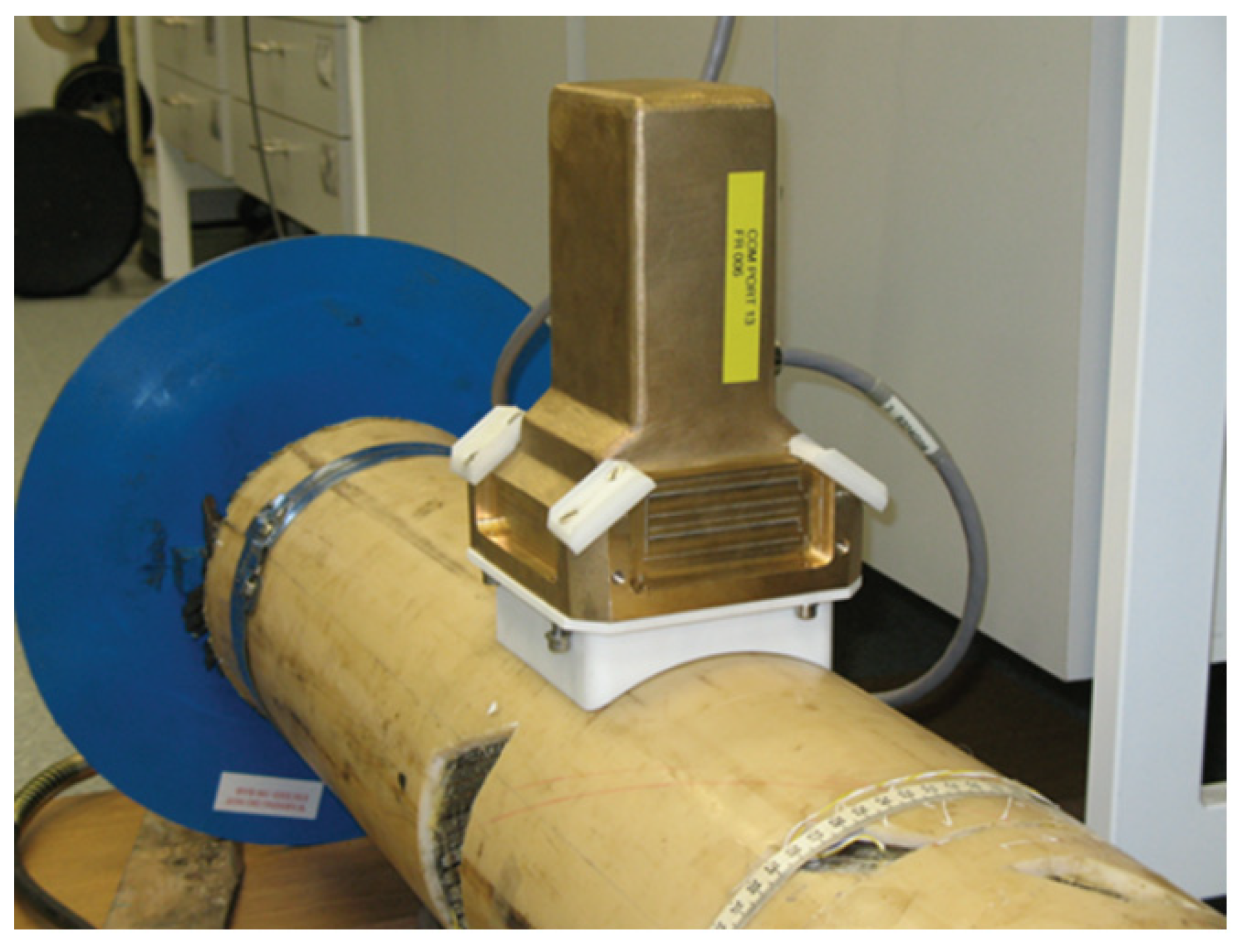
2.5. Reflectometer for Optical Backscatter

Sensors that interpret and analyse light reflections in optical fibres are referred to as fibre optic sensors (FOS). Distributed fibre optic sensors (DFOS) generate temperature or strain fields based on the scattering process in the optical fibre, which is decoded by software [134,135]. The optical fibre has a tiny diameter of 155–195 m, a high spatial resolution, and is sensitive enough to detect minute changes while maintaining a wide measurement range. The measuring range can be very extensive, ranging from one to several thousand metres, although the length will reduce the measurement’s spatial resolution. Spatial resolution refers to the precision with which data are captured, which can be as low as 1 mm [10,136].
The optical backscatter reflectometer (OBR) is a device that uses optical fibres to detect changes in strain. The programme allows for continuous measurements along the optical fibre’s whole length. The optical fibre, referred to as the main fibres, is carefully positioned across the areas to be examined and connected to the OBR via shielded optical fibres, referred to as secondary fibres. When composite production equipment is removed, the optical fibre is commonly embedded in composites or polymers, but it can easily break. Optical fibres are typically installed in the composite fibre direction [137,138]. The OBR generates a probe signal by emitting a laser beam from the light source. Rayleigh backscattering is caused by natural flaws or a fluctuating reflective index along the length of the optical cable. The detected signal is backscattering, which provides continuous sensing locations along with the optical fibre based on information from the reflected pattern and backscatter time. When the optical fibre deforms, the reflection pattern changes. The signal can be turned into a function of length by comparing it to a reference signal. The strain response will cover the entire length of the optical fibre in a single test and provide information about the structure’s overall behaviour. Two-dimensional strain fields can be created by arranging the optical fibres in a grid. In the programme, parameters such as gauge length and sensor spacing are defined, which specify the virtual sensors along the length of the optical fibre. Strain is calculated by averaging the backscattered signal’s displacement over the gauge length for each virtual sensor [138]. The measurement points will overlap if the gauge length is greater than the sensor spacing. The sensing length divided by the sensor spacing gives the number of measurement points. The best mix of these factors is different for each measurement, as data with a short gauge length will contain more details, while measurements with a long gauge length will reduce scatter in the measurements [10]. OBR is a relatively new technology for strain measurements that has been shown to be a promising measurement technique [10,136,137,138,139,140]. Since optical fibres have been applied practically, although they are typically time-consuming and difficult, they have contributed to research findings [60,141,142,143].
The OBR was utilised by Grave et al. [137] to measure the strain field emerging in a composite patch glued to a metal I-beam during a four-point bending test. There was a 20 mm machined crack in the centre of the top flange of the I-beam, which was terminated by a 6 mm hole. The composite patch was made of carbon fibre composite with a galvanic protective layer of chopped strand mat below. The optical fibre was installed in two places: one was embedded in the composite laminate and would measure the strain arising from the adhesive contact, while the other was positioned on the composite patch’s surface. For comparison, four electrical strain gauges were mounted on the patch surface. The strain obtained from the physical test at high loads differed from that derived from the linear finite element analysis (FEA) in the Abaqus model. The reason for this was damage development in the composite, which was not accounted for in the FEA but demonstrates the OBR’s ability to detect damage early. High strain gradients resulted in noise in the measurements, which may have been reduced with postprocessing. Finally, OBR was used to successfully assess the repair.
Optical fibres can be inserted into composite materials using OBR to assess structural health in composite pressure pipes to investigate impact and burst tests [139]. The optical fibre design allowed for high-resolution strain measurements throughout the whole surface of the pressure vessels. Optical fibres are normally inserted parallel to the composite layup, but this is not always the case with filament wound constructions. The optical fibres were placed between the hoop layers, although the pitch angles of the optical fibres and the composite layup varied. The optical fibres were spaced 20–30 mm apart, resulting in a pitch angle of 2.6°–3.9° for the optical fibres and 0.65° for the composite fibres. In addition to vacancies, this offset creates resin-rich patches around the optical fibres, and if the composite material fractures owing to high levels of pressure loads, the matrix cracks can cause significant local strains around the optical fibre, disrupting the signal. The variation in pitch angle, on the other hand, is tiny and produces only minor disruptions to the laminate, with no significant effect on the composite’s qualities. Optical fibres were also used in a grid in the centre of the pressure vessel to detect strain caused by impact loads.
When disassembling from the filament winding machine, several fibres failed at the point where the fibre egressed from the laminate; only 50% of the optical fibres were intact after manufacture. According to Lamvik [10], this problem was overcome by placing a patch of glass fibre composite over the area where the optical fibres were vulnerable, and almost all fibres remained undamaged. In that study, strain measurements were carried out with the help of LUNA OBR 4600 [134,135]. The resolution can be changed by adjusting the sensor spacing and gauge length parameters. The gauge length is essentially the length of a virtual strain gauge, and the sensor spacing is the distance between these strain gauges. Unlike regular strain gauges, these virtual strain gauges can overlap. Saeter et al. [139] used three different sets of parameters in their experiments: gauge lengths of 5, 10, and 30 mm, and sensor spacings of 1, 5, and 10 mm, respectively. With a gauge length of 5 mm and a sensor spacing of 1 mm, a very fine spatial resolution is achieved; however, local variations in the data may occur. These oscillations can be averaged and thus avoided with a coarser resolution if the strain field is close to a homogeneously high spatial resolution is not required.
An important aspect of this monitoring study is acoustic measurements. It is not uncommon for noise to be present in measurements. As the load levels increased, the strain measurements became noisy, as noted by Saeter et al. [139]. Noise can be caused by faulty splices, improper connections, or excessive curvature in the secondary or primary coated optical fibre. Damages to the optical fibre itself, such as hits or probable voids, can result in a signal with disruptions.
As previously stated, when the orientation of optical fibre and composite fibre differs, voids, and resin-rich areas are widespread; therefore, a bigger pitch offset results in higher noise levels. Noise can be introduced by post-processing, and some strain calculation settings can increase noise. The trials conducted by Saeter et al. [139] served as the foundation for a subsequent report by Lasn et al. [140], one of the main goals of which was to localise the damage detected by the OBR. When studying impact damage, the simplest detection method depends solely on the backscattered signal from optical fibres. In the measurements, the end of the optical fibre appears as a high peak. If the optical fibre breaks owing to a heavy load, the end of the fibre, and hence the peak in the measurements, will shift. This method is easy and effective; however, it is only effective if the fibre breaks. This will also limit the amount of data that can be collected in future measurements.
When a network of optical fibres was subjected to an impact load, stresses were computed by Lasn et al. [140]. To locate the damage, a strain map was created in post-processing, with a dot representing the strain value and a hoop and axial position indicating its location. A larger dot denoted a higher strain value. This not only helped to locate the damage, but it also helped to visualise the contour of the damage. The helical orientation of the composite fibres, which were coiled at a 15° angle to the axial direction, coincided with the orientation of the damage [10]. The strain was measured using a running reference approach rather than matching each measurement to an initial reference in the studies conducted by Heinze et al. [141] and Saeter et al. [139]. The running reference method calculates strain by comparing each measurement to the preceding one, and then combining the strain differences to get an absolute amount of strain. When the optical fibre is subjected to specific physical conditions, such as microbending or pinching, noise enters the measurements, and the strain values produced are not always useful. In situations when the standard method fails, such as the previously indicated conditions for the optical fibre or very high load levels, the running reference method obtains meaningful strain values with reduced voice [139]. It was further reported that noise will be present at high levels of pressure loads (near failure) and around damaged areas, although it can be misinterpreted as a symptom of damage, such as matrix cracks.
When composite materials are subjected to impact loads, they are prone to delamination, especially near free edges. The OBR was utilised by different researchers to detect and localise delamination [59,60]. In the study by Diaz-Maroto et al. [60], the colour strain map and the ultrasonic inspection of the sample investigated were able to visualise the first ply failure and delamination in the sample, as seen in Figure 6 and Figure 7.
Optical fibres were inserted and attached to the surface in a dense network with 5 mm spacing between each fibre. The optical fibre linked to the surface will experience residual strains because of delamination, indicating the location and level of damage. Delamination was detected via experimental tests on composite laminate plates with a [0n/90n]S layup, with the number of layers n varying between 2 and 4 for different specimens. A drop weight testing machine was used to provide impact stress to the specimens. Delamination was discovered on both the edge and near edge of the board. Delamination was identified and confirmed by visual inspection in the first example. The damage in the latter example was internal and could not be seen with the naked eye but was confirmed by ultrasonic C-scan inspection. The measurements revealed a delaminated zone with a residual strain field change of 200. Finally, OBR proved to be a promising technology for detecting and localising delamination in composites.
Composite bonded lap joints, which are an effective connecting method for composite constructions, are routinely monitored via optical fibres. Fatigue tests were performed using fibre-optic sensing devices as a potential method for monitoring such structures [141,142,143]. A single lap adhesively bonded CFRP joint was subjected to a 3.5 kN load with a test frequency of 10 Hz until failure at 60,000 cycles in the former. The optical fibre was bent such that it could monitor four segments on the front surface and two segments on the back surface with just one optical fibre. By halting the test every 5000 cycles, the measurements were taken at the mean load value. The whole strain profile and the minimum strain value were acquired from the OBR readings. From the FEA conducted, it was discovered that minimum strain and crack length had a linear relationship. Wong et al. [143] put a flush-step lap joint of CFRP through a fatigue test. One optical fibre was looped onto the surface and used to monitor the junction on both sides. An extensometer was used to determine the relationship between strain and load. With a frequency of 5 Hz, the specimen was subjected to a peak strain of 1000, which was increased to 2000 after 100,000 cycles. The test was carried out until it failed after 250,000 cycles. Increased strain values in the past 3500 cycles were indicative of damage prior to the breakdown. Optical fibre sensors have proven to be a promising approach for damage assessment and monitoring of fatigue crack propagation, with great potential for incorporation in structures for monitoring while in operation.
The research previously mentioned is primarily focused on lab experiments. The OBR was used to monitor real structures in Barcelona in a study by Barrias et al. [144] on the Sarajevo Bridge in Barcelona, Spain, which was monitored while it was being built without the bridge being closed to traffic. The goal was to detect changes in the bridge’s structural behaviour during and after construction, as well as to determine the bridge’s structural safety. In areas prone to stress increases and cracking, optical fibres were installed along the length of the bridge. The measurements were taken on two 50 m optical fibres. The monitoring took place over a nine-month period, with readings taken during certain monitoring periods. Temperature variations affect the behaviour of both the structure and the optical fibre over such a long monitoring period. This temperature effect has an impact on both the refractive index and the substance of the optical fibre. This can be mitigated by using point-to-point thermal compensation or loop-based thermal compensation. These compensating methods rely on a piece of optical fibre being unbonded in a tiny tube or loop. Thermal correction by loop was applied in this case. From the strain produced from the bonded portion, the strain depending on the refractive index and the strain dependent on the optical fibre’s thermal expansion are eliminated. The measurements revealed that the optical fibres were successfully installed. The OBR was successfully used in the model to obtain measurements over time. Finally, across a wide range of applications, OBR has provided satisfactory monitoring results. Experimental tests and finite element analysis are required to ensure that this is the best option for the specified application. Finding the most significant life-limiting factor for glass fibre composite repair and conducting tests accordingly is reasonable. Since the glass fibre composite bands employed for the repair can be woven, some voids and resin-rich areas can be expected surrounding the optical fibres. As a result, measurements acquired using optical sensors may have more noise than the OBR’s potential, and the running reference approach for strain analysis may be appropriate.

3. Methodology and Design Approach

This section presents the methodology and design approach proposed for composite risers.

3.1. Design Approaches

3.1.1. Design for Local Loading

The first design is a composite riser using similar designs for the layers, considering the number of layers and type of material, and the lay-up configuration. Since the composite riser is multi-layered and has a structure that is quite complex, the design is simplified by removing sophisticated cases, and stating all assumptions considered, such as that the manufacturing of the complex riser is a perfect CPR product. Additionally, since the design of the composite riser incorporates more variables, unlike the design of the steel riser, three stages were approached in the local design of the composite riser tube, starting with the geometry design. It is also noteworthy to add that the composite tube is made up of the liner material, the liner thickness, the layup configuration, the laminate arrangement, the composite layer thicknesses, and the subjected local loadings. The local design should first be performed to generate the first estimate of the laminate required, the composite body, its wall thickness, liner thickness, and the laminate configuration [27,28,29,30,31]. This can be obtained by considering different computations, such as composite theories, homogenisation, or the Netting theory [31,32,33]. If the forces and stresses on the composite body increase, the configuration and thicknesses of its liner and composite body can then be modified and redesigned. Additionally, if it led to some increase in moments acting across the lengthwise cross-section of the composite riser, then some structural reliability is required upon redesign. Under global loads, these moments can be determined by the large deformations to which they are subjected. These moments are also dependent on the cross-sectional tubular geometry of the composite riser. Note that these global loads can be computed using environmental weather conditions obtained from ocean monitoring as recorded in guidance bulletin [145]. On the other hand, the local design can be carried out by utilising layered solid elements in finite element analysis (FEA) to determine the stress distributions in each layer of the laminate with precision [23,27,34,146,147,148].
The design moves on to the second phase once the local geometry has been tentatively determined. In this stage, the entire riser is analysed under global stresses to evaluate its critical condition sites, as well as the load combinations that can be used at these locations. Pipe elements that are one-dimensional are used in FEA for global analysis, such as layering 3D elements over the whole surface. The third stage of the design is the structural verification of these main areas, which is defined by the global forces, pressures, and moments operating on them. A major design consideration will be the length of the riser. For instance, a 2000 m-long riser would be prohibitively very computationally expensive. Thus, a second 3 m or 5 m model can be considered in the local design to reduce computational resources and for ease of modelling.

3.1.2. Design for Global Loading

In this research, the composite riser was designed based on the criteria for extracting natural resources from a depth of approximately 2030 metres in the Gulf of Mexico (GoM) using the API RP2Int-Met standard [145]. In global design, two different design configurations are considered. This second design uses the global load and platform load on the marine riser. The type of marine riser configuration is also important, such as the TTR configuration attached to a SPAR platform, submarine hoses on floating buoys, and semisubmersible platform [149,150,151] with a metallic tension junction at the top and a metallic stress joint at the bottom, called the bottom joint. The first model recommended in the initial phase of the design is a steel riser, which is designed for minimum weight requirements and as a base case design for benchmarking. The loading requirements include functional and environmental loads in both local and global cases in accordance with the respective industry specification(s). Figure 8 illustrates a floating structure with marine risers and mooring lines.

3.1.3. Design for End Fitting, Liners, and Metal–Composite Interface (MCI)

Since the riser would have a liner and an end fitting, as well as mid-joint sections that are metallic, there is a need to also investigate the effect of the metal–composite interface (MCI) in the design. The investigation was also carried out on the MCI with layered 3D elements to precisely determine the stress distributions on the composite riser tube, its liner, and its end fitting. For the end fitting design, four different end fitting models were considered, but one was chosen with justification based on its performance. Additionally, the results of the study were checked against the material limits. In the design, certain checks were made to ensure safety factors (S.F). Any of the design models with S.F that does not fulfil the design requirements would require the component being redesigned, as well as the complete design process being repeated. The design models that passed this requirement were presented.
Based on the liner considerations, there are different distinct material combinations to choose from, including high-strength and high-modulus materials. As for the composite tubular structure, the material specifications include metallic liner materials, thermoplastic/ thermoset matrices, and fibre reinforcements. For the fibre reinforcements, carbon fibres and glass fibres were comparatively studied in this research.

3.1.4. Design for Optimisation

The composite riser must be modelled first, and then the design can be optimised later. There could be various composite material combinations. These designs can be developed to be as light as possible by utilising unique methodologies. These could be traditional (or conventional), local, and customised (or tailored) design techniques. The traditional design considers layout in axial and hoop directions without any off-axis directions. Only fibre is considered in this strategy, which has been used in many earlier projects [152,153,154,155,156,157,158,159,160,161,162]. However, the later strategy of the customised design includes reinforcements in the axial and hoop directions, and analyses those in other intermediate angles that are optimised for the smallest possible angle [163,164,165,166,167,168,169,170,171,172,173]. However, optimisation of composite riser design should be included in design guidelines. One challenge that is faced numerically is the computational resources and number of run times required to achieve a composite riser optimisation model. Detailed investigations on the weight of the composite structure, with some considerations for optimisation, have also been conducted [29,30,31,32]. In these studies, the three design methods have been applied, with some optimisation. Comparisons can be made between the optimised model and the tailored model used to verify the design approaches and materials selected using different mathematical optimisation methods.

3.1.5. Design for Motion Response and Stability

The design of the motion response and stability of the composite risers was based on studies of their hydrodynamics and mechanics. A somewhat ‘flexible design approach’ can be considered by using a hybrid layered structure having composite layers. This makes it easier to incorporate the riser model into a floating platform and investigate its response based on the design of the motion and stability of the floating structure. In some aspects of ocean engineering research, the motion and stability of other structures, such as semisubmersibles, can also be examined, and incorporated with marine risers, mooring lines, and tensioners. However, further work on the composite riser by requiring new configurations led the direction of the research to consider the design. Engineering systems are designed and investigated using the requirements of industry standards. Depending on the application, the effect of different components, such as hawsers, mooring lines, and the motion offset, can also be looked at for further incorporation into design guidelines. In that case, different ocean and weather conditions were considered to obtain the wave spectra. For global design, weather conditions are used based on weather reports and real-time data. As seen in the typical parameters for the global design in Table 1 and Figure 9, different environmental conditions could be considered for designing composite risers. The selection for oceans, waves, and currents depends on the varying weather conditions around the word. Environmental data for global rising sea levels and global climatic weather conditions are available in Figure A3 and Figure A4.
This data is necessary to ensure that the composite riser is safely designed and that the design can operate in deep water environments. It also enables an understanding of the effect of riser integration on the supporting structure and the level of motion response from the marine riser system across various regional seas. The effect of phenomena such as wave–current interactions and vortex-induced vibrations (VIV) can also be conducted, as illustrated in Figure 10.
Numerical investigations can be conducted using the CFD model using ANSYS Fluent and Simscale’s OpenCFD to investigate the effect of drag coefficient, flow patterns around the floating buoy, vortex identification on the structure, and VIV on the riser. The designs for investigating wave–current interactions (WCI) can be carried out using hydrodynamic diffraction analysis in ANSYS AQWA. The wave parameters can be developed by utilising the flow’s potential theory. This represents the dynamics of the flow with a velocity potential that changes with time and distance. Using the flow potential, a calculation of the flow’s force parameters can be obtained. This eliminates the challenges related to the complexity of flow rotation and separation. The study of the VIV included system coupling from the ANSYS ACP into ANSYS Fluent, which can provide insight into the challenge from the vortex shedding effect on the composite riser [26,102].

3.1.6. Design for Weight Savings and Strengths

In the design of the composite riser, the aim is to reduce deck loads by having a novel composite riser that has light weight as well as strength. From some investigations, different composite riser models have been developed. There are diverse findings on the best combination, such as AS4/PEEK, as each design is relative to the requirements of this investigation, the design parameters, and the numerical model. Based on the global design, the wave, current, and wind loads can be extracted from the hydrodynamic analysis using numerical tools, such as WAMIT, ANSYS AQWA, ABAQUS AQUA, and Bentley’s Moses. This can be applied as the loading conditions in the FEM by coupling it into Orcaflex from ANSYS AQWA. The static loads include the buoyancy force acting upwards, the riser weight, the mooring weight, the weight of liquid stored in the columns, the load of the facilities, the operating loads, the topside weight, and the hull steel weight. The results obtained from the FEM and CFD studies can be used to make some conclusions and recommendations on the following aspects:
  • Laminate configuration;
  • Design approach for weight savings;
  • Laminate thicknesses;
  • Liner design and materials to use;
  • Nature of steel grade and the materials to use;
  • Marine riser design;
  • Composite tube design;
  • End-fitting design;
  • Recommendations for layer thicknesses;
  • Marine hose and composite riser designs;
  • Configurations for composite risers;
  • Guidance on Dynamic Amplification Factor (DAFhose);
  • Recommendations for composite riser motion response; and
  • VIV of composite risers and supporting structures.

3.2. Model Development

Based on the model development, there were five sets of numerical models recommended against different experimental models that can be developed to understand the behaviour of the composite riser based on its hydrodynamics and mechanics, with a response when attached to floating structures; these are:
Composite model: This was set up to design the composite structure, such as a composite production riser (CPR), which can be modelled as a multi-layered structure with 18 layers with different configurations. Depending on the designer’s choice, it can be developed using different numeral tools, such as ABAQUS or COMSOL composite module or ANSYS ACP module, linked to ANSYS Static Structural, ANSYS Mechanical, and system coupled.
Mechanical model: The mechanical model is a benchmark model of the steel riser used as a benchmark model. It was also used when modelling the metallic aspects of the composite structure. Using the case study of CPR, the mechanical model can be used to model its metallic liner.
Finite element model: The finite element model (FEM) is developed to investigate the safety factors and stress magnitudes on the different layers of the composite riser under static load and dynamic load cases. In CPR studies, the FEM is also developed for the static loads in ANSYS Static Structural, Solidworks 2020, ANSYS Design Modeler, ANSYS ACP, and Orcaflex. The FEM can be used to investigate the strength of the CPR, the fatigue behaviour, the impact analysis, the tensile properties, and the deformation profile of the marine riser.
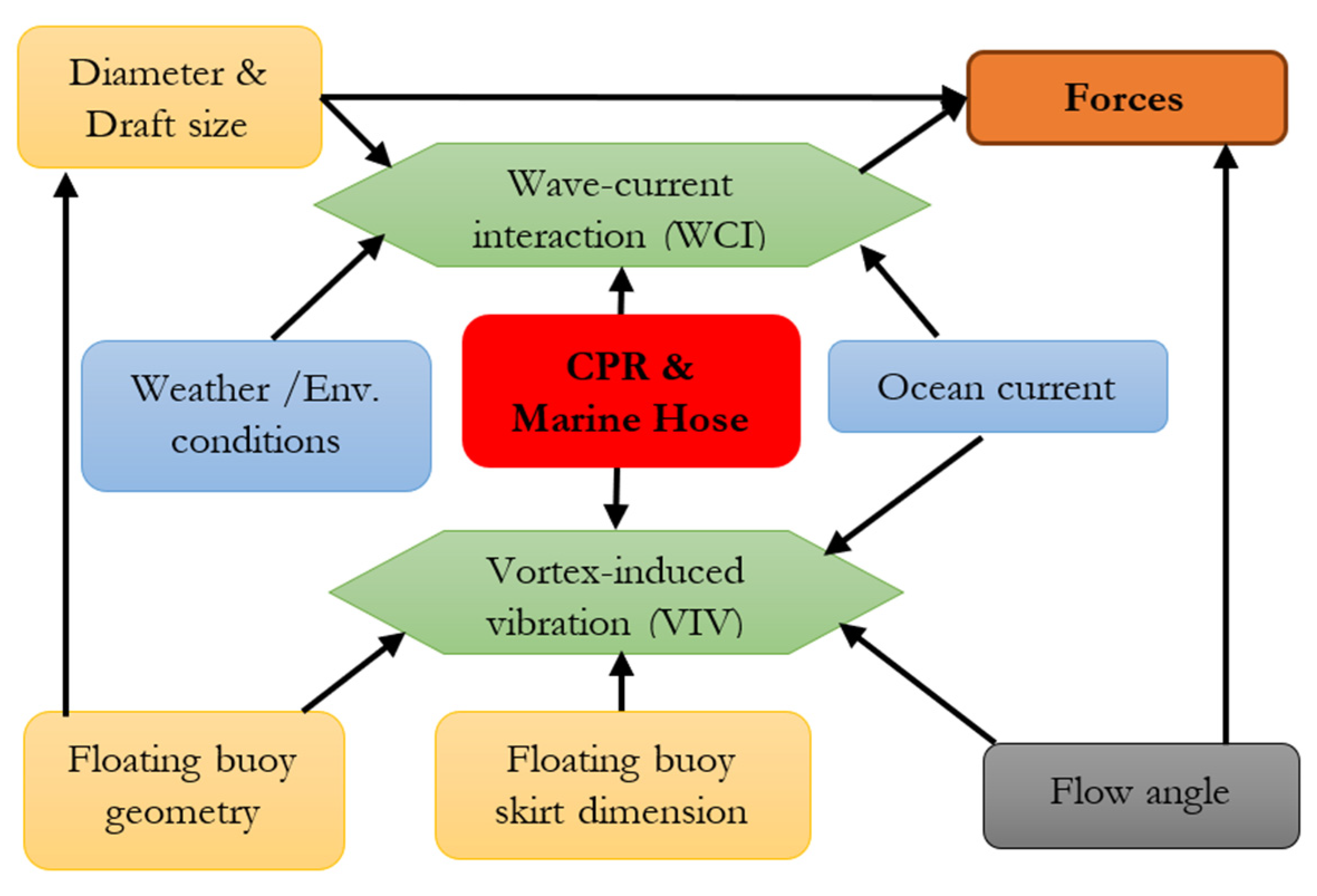
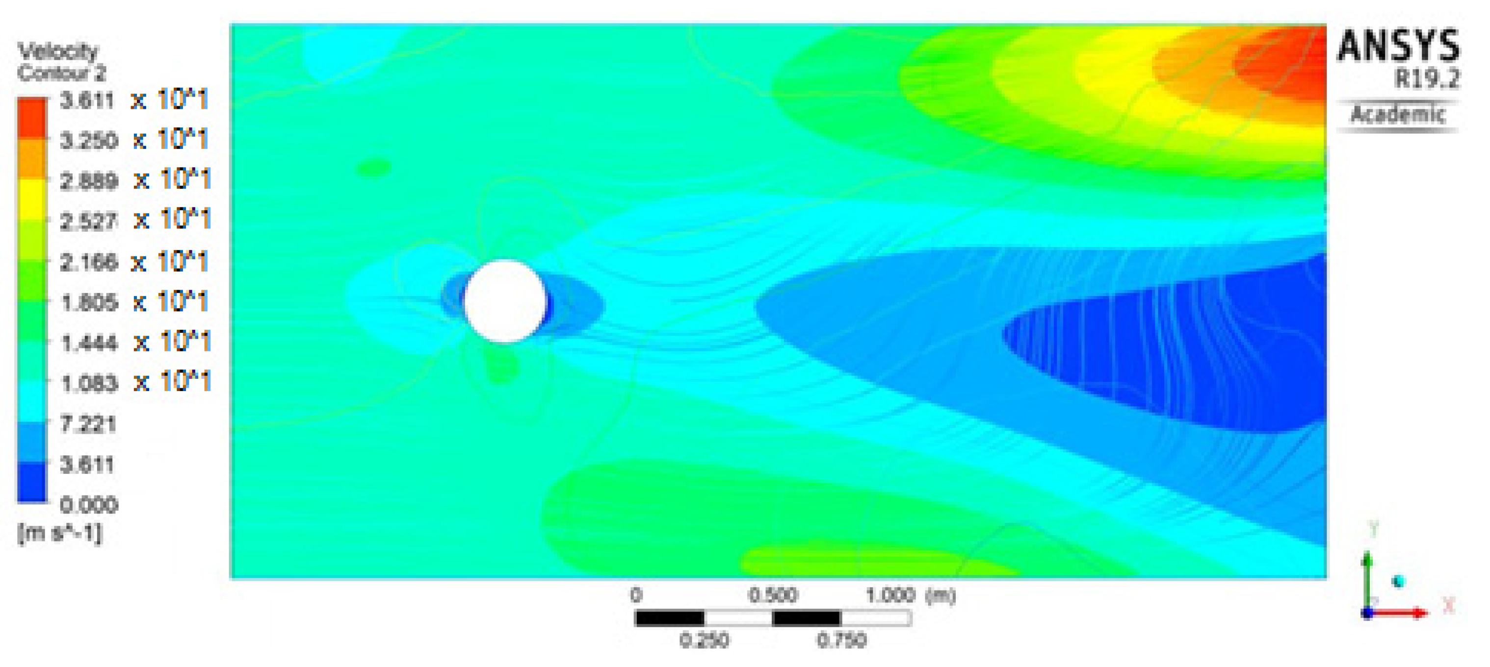
CFD model: The flow around the marine riser can be investigated for vortex effects. This is usually conducted using a computation fluid dynamics (CFD) tool, such as ANSYS Fluent, ANSYS CFX, or COMSOL Multiphysics. The model is developed by considering the nonlinear drag parameter, flow around the floating buoy, and effect of strakes on the riser as modelled in this study. The CFD model can then be further developed in the later stage of the project to understand the nature of flow around the hull, such as a tension leg platform (TLP), Truss SPAR, or semisubmersible hull. It can also be conducted to understudy the effect of flow around the riser, when risers are integrated into the floating structures, the effect of Vortex-Induced Vibrations (VIV), and the effect of strakes on the risers. The oscillation from the waves and drag effects on the structures are recorded, and reciprocating shed vortexes can be observed. Figure 11 shows a typical illustration of the flow pattern and vortex effect around the structure examined in the CFD study.
Hydrodynamic model: Hydrodynamic aspects can be set up to investigate the motion response of the composite riser under wind, current, and wave loads. CPR can be developed in WAMIT or ANSYS AQWA using the Boundary Element Method (BEM) using pipe elements and Morison elements. The AQWA model was also coupled with Orcaflex for the hydrodynamic model, as Orcaflex applies line theory. It is noteworthy to add that the hydrodynamic model can be developed using diffraction principles to characterise the motion behaviour of both the TTR composite riser and the composite submarine hose models. Current practice requires that they be modelled using the response from wind, wave, and current loads by considering industry standards and specifications. The Boundary Element Method (BEM) could be used to conduct this investigation in ANSY AQWA, as the BEM formulations are used in the AQWA package. The AQWA solver solves a set of complex partial differential equations describing the flow potential near the incidence, diffraction, and radiation boundaries. The force, pressure, and moment parameters can then be computed after resolving these sets of equations. A wave spectrum was used to study complex and irregular wave behaviour. The influence of drift second-order factors on the hull’s reaction behaviour in complicated wave flow was explored. Interactions between currents and waves should also be considered. The hull’s response can then be investigated under the time and frequency domains using the basic motion equation for a single degree of freedom (DoF) system, with multiple line matrices built to compute succeeding degrees of freedom. However, various software packages may produce different results, but they may be similar, depending on the study investigated when compared, and validated before use.
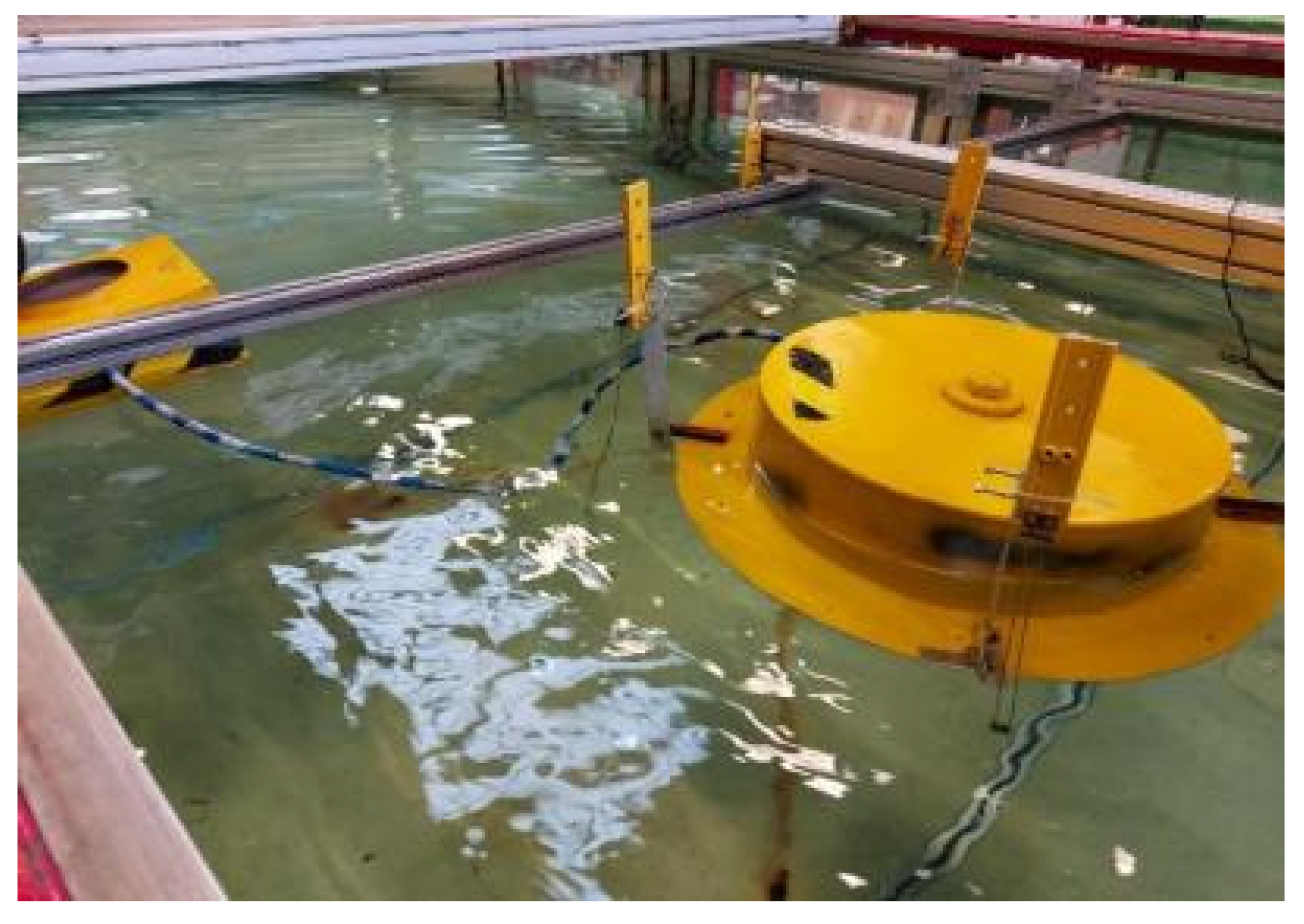
Experimental model: Validation of the model should be conducted to ensure the validity and correctness of the hydrodynamic model. This can be achieved by experimental studies set up using a wave tank testing facility, such as the Lancaster University wave tank. The motion of the scaled-down risers will be attached to the hull models of a floating platform. Data are outputted during the experiment, which must be recorded. However, to ensure consistency in the design, different runs are required. The experimental results with the attached risers on the floating structure’s model can also be presented. However, there are also different approaches that could be applied in any experimental investigation. Figure 12 shows an experimental model in a wave tank.

3.3. Analysis Setup and Software Utilisation

During this research, the design of the composite risers involved a combination of various commercial and open-source software.

3.3.1. Setup for Numerical Analysis

  • For the FEM models, the numerical setup was developed in ANSYS Structural, Solidworks, ANSYS ACP. Others were on ANSYS APDL, ABAQUS, and Simscale OpenFEA.
  • For CFD analysis, the numerical setup can be developed in ANSYS CFX, ANSYS FLUENT, COMSOL Multiphysics, and OpenCFD.
  • For hydrodynamic diffraction and response analysis, the numerical setup can be developed in ANSYS AQWA and Orcina’s Orcaflex.
  • The CAD models can be built in SolidWorks, ANSYS Design Modeller, and Autodesk Inventor.
  • For the FSI (fluid–structure interaction), ANSYS Hydrodynamic and ANSYS Diffraction models can be used.
  • A numerical setup for risers and mooring analysis can be developed in Orcaflex and ANSYS AQWA.

3.3.2. Setup for Experimental Analysis

  • Wave tank testing facility;
  • Regular waves: sea state and sinusoidal wave;
  • Imetrum System for DIC (Digital Image Capture);
  • Electronic wave gauges;
  • LabView Software;
  • Edinburgh Designs wave tank software;
  • WitMotion Bluetooth Sensors; and
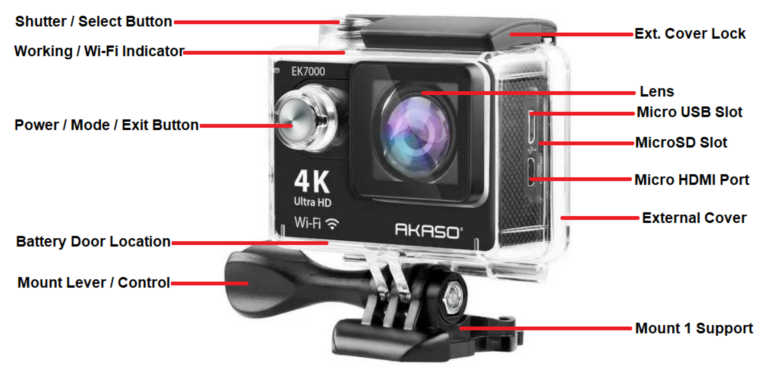
  • Akaso 4k Underwater Video Camera (see Figure 13).

3.3.3. Software for Modelling and Analysis

Different marine riser analysis software programmes can be applied to both riser-specific and general-purpose software packages currently available. Table 2 presents the most widely used marine riser software. The data were compared for institutional usage by comparing the software available in the authors’ affiliations as case studies using Lancaster University, UK and Universiti Teknologi PETRONAS, Malaysia at the time of this investigation, which were also applied in this research, as presented herein.

3.4. Qualification and Standards Utilisation

During this research, some standards are recommended for designing, qualification, and monitoring composite risers, as discussed in this section.

3.4.1. Qualification

A component’s qualification certifies that the component’s structural integrity has been retained. Component management is a crucial aspect of the qualification process. Both theoretical assessments and verification by testing are carried out in accordance with relevant standards to qualify a structure. For qualification, the composite riser pipe must be tested thoroughly to ensure that it can perform during the in-service case [174,175,176,177,178,179]. For theoretical assessments, some numerical models or simple test cases may be provided, and the numerical models used must be well validated. Furthermore, the design, installation, and maintenance of the specific application must meet the requirements of industry standards and guidelines; otherwise, it will not be in service. After that, the most important standards are provided, along with a brief explanation of how they are qualified. It is important to make some observations on related industry standards for the qualification of composite risers.

DNV-RP-F202: Composite Risers

This standard provides the recommended practice for the application of composites to marine risers, though with some limitations. There is insufficient information on practical data, design limits, recommended composite materials, and global design investigations using a floating platform. However, it specifies very helpful guidance on the design of composite risers. The physical properties of the composite are modified when exposed to external conditions over a long period, such as a year, and the impacts usually increase over time. Due to their chemical differences, the fibre and matrix react differently to environmental circumstances. Environmental resistance is influenced by the fibre matrix interface, void content, and matrix cracks. Temperature, water, chemicals, and UV radiation are among the environmental factors considered by the standard. Seawater is said to have a milder effect than fresh water. The composite is influenced more severely by the combination of water and high temperatures than if the influences occurred separately.

DNV-GL OS C501: Composite Components

This standard outlines rules and guidelines for the design and analysis of composite components, as well as their modification, operation, and upgrading. It is applicable to all composites. The importance of environmental loads and circumstances in the offshore business is stressed, as well as factors such as paperwork, verification, and inspection. There are specifications for composite restorations that are predicated on reaching the same level of strength and functioning as the original construction. A composite repair is essentially a laminated joint, with the interface for load transfer being the most important component.
Testing can be done to qualify a component or to confirm the accuracy of an analysis or design calculation. No failure will be critical for the component’s functionality or safety, according to testing and analysis. The evaluation of likely failure causes is critical for a particular application when long-term performance is required. The test specimens must be accurate representations of the component in question. Only the load situations and environmental circumstances examined are valid for the test findings. The failure mode(s), failure mechanism(s), and failure location(s) must all be documented and validated.

ASME PCC-2-2015: Repair of Pressure Equipment and Piping

During the service life of equipment and pipelines, this standard defines how to design, construct, evaluate, and test repairs. This standard is primarily intended for broad applications and may not be appropriate for everyone. Testing is required to determine mechanical and thermal parameters, such as tensile strength, in-plane shear modulus, lap shear adhesion strength, and thermal expansion. A minimum value (if applicable) is specified, as well as which test method applies to which property.

DNV-RP-C301: Design, Fabrication, Operation, and Qualification on Bonded Repair of Steel Structures

For bonded repairs, this paper outlines rules and recognised techniques. Chemical and thermal loads may hasten the breakdown of such repairs, which are sensitive to environmental stressors. Non-destructive inspection (NDI) technologies, such as ultrasound and x-ray, are recommended for detecting laminate delamination. However, no technology is recommended for detecting bondline faults. If the repair is to be exposed to thermal fatigue, long-term tests are required to establish the effects of thermal loadings. It is pertinent that there should be proper documentation of the long-term tests, ultrasound tests, x-ray tests, and other non-destruction inspection reports.

DNV-RP-A203: New Technology Qualification

This best practice outlines a method for systematically qualifying new components, equipment, and assemblies that use new technology, mostly for offshore applications. Furthermore, qualified technology in a novel location or previously qualified components integrated in a novel manner are both considered innovative technologies. There are five steps in the qualification procedure. The qualification basis is developed first, followed by the qualification requirements. The technology is also evaluated, with obstacles and uncertainties noted. Threats are assessed, and failure modes are identified based on the level of criticality which is determined by the risk to the components as well as the system. The activities necessary for the qualification are then designed, completed, and documented.

3.4.2. Standard Utilisation

In research, one of the findings is that there are limited standards for composite risers [106,107,174]. The limitation of the application of composite risers includes the elaboration of these standards, which is not considered in this study, but recommendations were made on standards for composite marine risers. Other issues that were not looked at are reliability analysis, and health and safety issues. In addition, some tasks require special codes to obtain some results and to develop new codes/programs to obtain the desired results. Additionally, several industry standards are utilised on marine risers, as there are limited standards specific to composite risers, as shown in Table 3. These are some recommendations, guidance reports, and industry standards related to composite risers, marine risers, and floating structures that can be considered at different stages.

4. Application and Case Study Analysis

The application of monitoring on advanced composites requires some discussion of its advantages, developments, and analysis of some case studies, as presented in this section.

4.1. Application of Advanced Composites

The composites industry appears to be waiting for “the big one”—the game-changing application that will drive composites into the mainstream of materials. Offshore oil has been identified as one such area with such potential. Composites have been gradually replacing topside (above water level) metal in a growing number of offshore facilities, in both new installations and retrofits of existing structures, for some time. However, large-scale applications, such as carbon composite riser pipes for deepwater drilling, are on the verge of commercial success, bringing the market very close to “big one” status for the first time. Composites have a significantly lower weight and far stronger corrosion resistance than traditional offshore materials, and regulatory and materials-certification organisations are increasingly accepting composites. Weight reduction is a primary driver since lighter structures cost less to construct and allow for more drill pipe and oil production equipment. “When installed costs are examined, the cost gap narrows, and when life-cycle costs are evaluated, the cost differential swings in favour of composites” [180]. Fibre-reinforced plastic pipes have been shown to save up to 70% during their lifetime. When manufactured with chemical-resistant resins, composites are almost corrosion free, unlike steel, which corrodes quickly in seawater. This corrosion resistance translates to years of maintenance-free service for platform components, such as column pipes (pipes that extend from the platform down below the water surface to provide seawater) and firewater systems (strategically located pipes for combating potential fires). Steel pipe installations are sometimes severely rusted after only two or three years of service, according to one Gulf Coast manufacturing factory, but thousands of composite column pipes are still in use, some of which are more than 25 years old.
Composites have also benefited from key regulatory changes in the last five years. On offshore platforms and drill ships, the US Coast Guard allowed the use of fibre-reinforced polymer (FRP) pipework and glass/phenolic gratings in late 1998, as given in USCG Policy File Memoranda (PFM) 1–98 and 2–98 [180,181,182,183]. The International Maritime Organisation (IMO) has certified composite pipes for use in water-carrying platform fire-fighting systems, as required by the IMO’s Level 3 Fire Endurance requirements (A.753), which include jet fire endurance criteria. (“Jet fire” refers to the high-pressure emission of burning hydrocarbons). However, IMO standards prohibit the use of composite pipes for flammable liquids, such as hydrocarbons or diesel fuel (Level 1 Fire Endurance), making certification doubtful. For composite piping applications, ISO 14692 (International Organization for Standardization) proposes a performance-based risk assessment. Det Norsk Veritas, a Norwegian certification company for seagoing vessels and structures, later released two composites’ standards: DNV-OS-C501 and DNV-RP-F202. DNV-OS-C501 is an offshore standard that specifies the requirements and methods for composite component structural design and structural analysis. On the other hand, DNV-RP-F202 is the Recommended Practice that prescribes performance-based guidelines for composite riser certification. Both point to a rising acceptance of composites in the design and construction of offshore oil platforms.

4.2. Advantages of Advanced Composites

Composites are becoming increasingly used in the oil and gas industry. Despite all the advantages of composites, the oil and gas industry has been slow to adopt composite solutions. This is sometimes linked to the industry’s old guard’s conservatism, which believes that steel is “good enough” to suit its needs. Another significant issue confronting composites is the lack of a universal design and qualification standard. Hence, this review on the monitoring of composite risers has been conducted by presenting some design approaches, and recommended standards. While composites are making advances into retrofitting older platforms, simple material substitution for immediate weight reductions or corrosion resistance does not fully harness the advantages of composites. However, with retrofitting, these potential benefits can be obtained from composites. During the design stage, composites will be key to lowering total platform system costs. In addition, platform engineers have a strong incentive to design with composites in mind, given the wide range of proven composite solutions now accessible. Despite all the advantages of composites, the oil and gas industry has been slow to adopt composite solutions. This is sometimes linked to the industry’s old guard’s conservatism, which believes that steel is “good enough” to suit its needs. Another significant issue confronting composites is the lack of a universal design and qualification standard. A minimum testing duration of more than a year and a half is necessary under the current requirements for a new composite pipeline product. Material testing centres assist in the development of non-metallic field application technologies that are ready to use. By strengthening existing qualifications and developing new service standards, inspections, and monitoring systems, the goal is to promote composite use. Composites also have huge potential for use in pipe systems, risers, umbilical and frac plugs, and balls used during hydraulic fracturing. There is a scarcity of meaningful performance data to contend with, especially in harsh offshore locations, which is a key impediment to composites’ progress. However, the advantages of composite materials exceed the dangers associated with novel material technology.
Another advantage is that composite piping saves weight and costs on the top side. Some forms of topside facility pipework use composites as standard equipment. Composite pipes may now be constructed to withstand even the most intense jet fire conditions using phenolic resins, fire-retardant additives, and intumescent coatings. While conventional fibreglass composite pipes are non-conductive, there is significant debate in the industry about whether conductivity is necessary on a platform’s open deck. Most manufacturers offer electrically conductive versions of their plumbing products for areas where operators want or demand them [180]. Composites are quite less pricey than the copper/nickel alloy commonly used for fire pipes. Composites have also been recorded as having the ability to be fabricated into fewer parts to fit into irregularly—shaped or sleek sections. Composite piping’s lower modulus allows for elasticity and flexibility in designs that would be impossible with a more rigid metal. Furthermore, bonded joints avoid the requirement for hot welding, which might be a fire hazard on a platform containing flammable hydrocarbons. Since composites can be ruined if dropped or struck by a large object, they must be treated differently than metal during installation.

4.3. Patent Publications

In the research on the guidelines for composite risers, patent publications for composite riser design are presented to discuss some developments made so far. These developments also show that some devices, apparatuses, and methods have also been patented on flexible risers and composite risers, which will aid in developing guidelines for composite risers. One particular standard that stands out is US20050100414 (also filed as CA2541542 and WO2005047641), whereby the system monitors the degradation of a composite riser string and ensures that its structural integrity is maintained. Composite riser structures with strain and vibration sensors are used in the system to assess variations in stiffness strain in the first and second orientations. Monitoring modules attached to each individual riser, as well as devices to convey data from the monitoring module to the surface controller, can be included in the system, as illustrated in Figure 14. When predetermined warning limits surpass, the monitor system can also sound an alert. Table 4 and Table 5 present some patents on monitoring devices and methods, with some of these related components for composite risers.

4.4. Policy Implications and Recommendations

In recent years, hybrid flexible composite risers have become more adaptable. Currently, flexible risers have proven to be one of the most popular riser solutions for various floating production systems in shallow to deepwater in many parts of the world due to their good dynamic behaviour and dependability. The flexible pipe is made up of numerous layers of plastic and steel. The weight of the riser is supported by a huge number of steel wires (known as tensile armours) that are critical to the pipe’s integrity. As a result, it is critical to be able to guarantee the integrity of those armour wires and to notice a potential failure early enough to respond. Some innovative monitoring methods, such as FBG, as applied in Figure 15, are based on a clamped composite structure with embedded optical fibre. They track permanent deformation (torsion and elongation) and deliver cross-referenced data to improve integrity assurance dependability.
Even though armour layers are critical to the structural integrity of flexible risers, operators, and service providers around the world are still looking for reliable inspection or monitoring techniques that can detect the presence of cracks or other defects in the metallic wires that make up the pipe’s internal and external armour layers. Some advice on monitoring systems based on acoustic emission, residual magnetic field measurement, optical sensing, or the use of visual monitoring cameras has been provided in the literature [184,185,186,187]. So far, technology that relies on optical fibre sensors has yielded the best results. The use of fibre Bragg grating sensors to directly measure strains in each wire of the external traction layer provides an accurate and reliable real-time, continuous monitoring technique, giving the operator valuable information and an early warning if any deviation from the expected wire’s structural behaviour is detected.
In addition, since flexible pipes could have relative issues, repairs could be achieved with composite repair technologies, such as ComposiSleeveTM, can be used on composite risers and other composite pipes [63,188,189,190,191]. Alexander et al. [63] recently presented an experimental investigation of the success of this repair regime using FBG sensors. Hence, composite tubes could also be repaired better by adequate monitoring and inspection of the onshore/offshore faults. In practice, monitoring provides a good alternative to standard maintenance methods because they may not always require shutting down operations [10]. A typical composite pipe repair system is shown in Figure 15.
Considering the technology applied in Figure 16, the sensors are placed on the area to be repaired and glued to it strategically, and then one end of the sensor is carefully linked to a wire onto a readout to obtain the readings after calibration. These composite riser repair systems have been developed using different techniques over time and have proven to be more effective under adequate monitoring [61,62,63]. The current repair practice considered for pipelines is the ANSI/ASME PCC-2 (ASME 2015); however, it is suggested to elaborate on the guidelines for composite riser repair. Figure 17 shows a typical composite pipe repaired using the ComposiSleeveTM sample, with the results shown in Figure 15.

5. Conclusions

The study proposes some guidelines for composite risers, with some design approaches and monitoring techniques. For the design, six different considerations are presented for the composite flexible riser. For monitoring, four different techniques are identified; however, more monitoring techniques are available. However, the following conclusions are drawn from this study:
  • The future of monitoring and leak detection is promising, with possible combinations of different technologies examined to provide the best available solution and optimum environmental protection.
  • This study has identified a knowledge gap in the standards for composite riser technology and aids in closing it. In addition, this study presents important advances made on composite flexible risers and related monitoring devices through published patents.
  • In comparison to other industries, such as aerospace, automotive, and construction, where composites have been widely utilised for decades, the oil and gas industry has been sluggish to adopt them. On composite risers, the study explains the technology and design approaches that are advised.
  • This study provides some guidelines for designing and monitoring composite flexible risers. The study also presents software, specifications, and guidelines that should be considered in designing the composite structure. It also proposes some design approaches as guidelines that are advised, with some policy implications.
  • This study presents characteristics of the monitoring techniques of composite flexible riser technology. The advantages of the monitoring techniques include aiding composite riser measurements, recording data from riser deformation, improving integrity assurance, and dependability of design from stable readings.
  • Composites could be used for hybrid systems as composite flexible risers and to repair offshore faults, as they are a good alternative to standard maintenance methods.

Author Contributions

Conceptualisation, C.V.A.; methodology, C.V.A. and A.R.; software, C.V.A., A.R., I.A.J., C.A. and C.W.; validation, C.V.A. and A.R.; formal analysis, C.V.A., A.R., I.A.J., C.A. and C.W.; investigation, C.V.A., A.R., I.A.J. and C.W.; resources, C.V.A. and A.R.; writing—original draft preparation, C.V.A.; writing—reviewing draft, C.V.A., A.R., I.A.J., C.A. and C.W.; data curation, C.V.A. and A.R.; visualisation, C.V.A., A.R., I.A.J., C.A. and C.W.; supervision, C.V.A.; project administration, C.V.A., A.R., I.A.J., C.A. and C.W.; funding acquisition, C.V.A. and A.R. All authors have read and agreed to the published version of the manuscript.

Funding

The Engineering and Physical Sciences Research Council (EPSRC)’s Doctoral Training Centre (DTC), UK, and the Department of Engineering, Lancaster University, UK, are highly appreciated. Additionally, Niger Delta Development Commission (NDDC), Nigeria, is also appreciated for funding via the Overseas Postgraduate Scholarship. The authors also recognise the support of the Standards Organisation of Nigeria (SON), F.C.T Abuja, Nigeria.

Institutional Review Board Statement

Not applicable.

Informed Consent Statement

Not applicable.

Data Availability Statement

The data for this study is not shared as it is an aspect of an on-going study on this present research.

Acknowledgments

The authors also acknowledge the permissions of different publishers and industry firms on the images used in this publication. The authors acknowledge the technical support from Lancaster University Engineering Department. The permission from Chris Alexander to use some images in this manuscript is also well appreciated.

Conflicts of Interest

The funders had no role in the design of the study; in the collection, analyses, or interpretation of data; in the writing of the manuscript, or in the decision to publish the results. The authors declare no conflict of interest.

Abbreviations

3DThree-Dimensional
APIAmerican Petroleum Institute
ASMEAmerican Society of Mechanical Engineers
BEMBoundary Element Method
CFDComputational Fluid Dynamics
DNVDet Norske Veritas
CADComputer-Aided Design
CFRPCarbon Fibre Reinforced Polymer
CPRComposite Production Riser
CRACorrosion Resistant Alloy
DFOSDistributed Fibre Optic Sensors
DICDigital Image Capture
DoFDegree of Freedom
DTSDistributed Temperature Sensing
ECAEngineering Critical Assessment
FBGFibre Optics Bragg Gratings
FEAFinite Element Analysis
FEMFinite Element Model
FOSFibre Optic Sensors
FRPFibre-Reinforced Polymer
GOMGulf of Mexico
HFPHybrid Flexible Pipe
IMOInternational Maritime Organisation
ISOInternational Organization for Standardization
IQIImage Quality Indicators
JONSWAPJoint North Sea Wave Project
LancsUniLancaster University
MCIMetal–Composite Interface
NASANational Aeronautics and Space Administration
NDINon-Destructive Inspection
NDTNon-Destructive Testing
NTNUNorwegian University of Science and Technology
OBROptical Backscatter Reflectometer
OTDROptical Time Domain Reflectometry
PFMPolicy File Memoranda
PVDFPolyvinylidene Difluoride
RIMRiser Integrity Management
ROVRemotely Operated Vehicle
SCRSteel Catenary Risers
S.FSafety Factors
SHMStructural Health Monitoring
SPARSingle Point Anchor Reservoir
SURFSubsea Cables, Umbilicals, Risers, And Flowlines
TCPThermoplastic Composite Pipes
TLPTension Leg Platform
TTRTop Tension Riser
USAUnited States of America
UTPUniversiti Teknologi PETRONAS
VIVVortex Induced Vibration
WCIWave–Current Interactions

Appendix A

Figure A1. Map of all the ships showing their real-time positions globally at sea, with data obtained through monitoring (MarineTraffic.com, accessed on 23 November 2017).
Energies 15 04982 g0a1
Figure A2. Map of all the ships showing their real-time positions globally at sea, with data obtained through monitoring (MarineTraffic.com, accessed on 5 June 2022).
Energies 15 04982 g0a2
Figure A3. Map of sea level rising conditions globally and extreme weather (Courtesy: Mapsofworld).
Energies 15 04982 g0a3
Figure A4. Map of global climatic weather conditions showing the climate across different geographical zones.
Energies 15 04982 g0a4

References

  1. Williams, J.G. Offshore Oil Composites: Designing in Cost Savings. Composites World, 26 February 2009; Issue 2. Available online: https://www.compositesworld.com/articles/offshore-oil-composites-designing-in-cost-savings (accessed on 11 May 2022).
  2. Williams, J.G. Composite Material Offshore Corrosion Solutions. In Proceedings of the International Workshop on Corrosion Control of Marine Structures and Pipelines, Galveston, TX, USA, 9–11 February 1999; Available online: https://www.bsee.gov/sites/bsee.gov/files/tap-technical-assessment-program//392aa.pdf (accessed on 12 May 2022).
  3. Reda, A.; McKee, K.K.; Howard, I.M.; Sultan, I.A. When is a subsea anchor required for a short pipeline/SCR system? Int. J. Pres. Ves. Pip. 2019, 171, 278–298. [Google Scholar] [CrossRef]
  4. Reda, A.; Rawlinson, A.; Sultan, I.A.; Elgazzar, M.A.; Howard, I.M. Guidelines for safe cable crossing over a pipeline. Appl. Ocean Res. 2020, 102, 102284. [Google Scholar] [CrossRef]
  5. Amaechi, C.V.; Chesterton, C.; Butler, H.O.; Wang, F.; Ye, J. Review on the design and mechanics of bonded marine hoses for Catenary Anchor Leg Mooring (CALM) buoys. Ocean Eng. 2021, 242, 110062. [Google Scholar] [CrossRef]
  6. Amaechi, C.V.; Chesterton, C.; Butler, H.O.; Wang, F.; Ye, J. An Overview on Bonded Marine Hoses for sustainable fluid transfer and (un)loading operations via Floating Offshore Structures (FOS). J. Mar. Sci. Eng. 2021, 9, 1236. [Google Scholar] [CrossRef]
  7. Díaz-Maroto, P.F. Structural Health Monitoring in Aeronautical Structures by Means of Distributed Fibre Optic Sensing Networks. Ph.D. Thesis, School of Aeronautical and Space Engineering, Polytechnic University of Madrid, Madrid, Spain, 2018. Available online: https://oa.upm.es/53147/1/PATRICIA_FERNANDEZ_DIAZ_MAROTO.pdf (accessed on 28 June 2022).
  8. Bai, Y.; Bai, Q. Subsea Pipeline and Risers; Elsevier Publishers: Oxford, UK, 2005. [Google Scholar]
  9. Kyriakides, S.; Corona, E. Mechanics of Offshore Pipelines: Volume 1: Buckling and Collapse; Elsevier Publishers: Oxford, UK, 2007. [Google Scholar]
  10. Lamvik, K.S. Monitoring of Composite Repair on Risers. Master’s Thesis, Norwegian University of Science and Technology (NTNU), Department of Mechanical and Industrial Engineering, Trondheim, Norway, June 2019. Available online: https://ntnuopen.ntnu.no/ntnu-xmlui/bitstream/handle/11250/2623204/no.ntnu%3Ainspera%3A2525072.pdf?sequence=1&isAllowed=y (accessed on 1 June 2022).
  11. Clarke, T.; Jacques, R.; Bisognin, A.; Camerini, C.; Damasceno, S.; Strohaecker, T. Monitoring the structural integrity of a flexible riser during a full-scale fatigue test. Eng. Struct. 2011, 33, 1181–1186. [Google Scholar] [CrossRef] [Green Version]
  12. Woo, J.; Kim, D.; Na, W.-B. Damage assessment of a tunnel-type structure to protect submarine power cables during anchor collisions. Mar. Struct. 2015, 44, 19–42. [Google Scholar] [CrossRef]
  13. Jie, W.; Yao-Tian, F. Study on Safety Monitoring System for Submarine Power Cable on the Basis of AIS and Radar Technology. Phys. Procedia 2012, 24, 961–965. [Google Scholar] [CrossRef] [Green Version]
  14. Reda, A.; Abu-Siada, A.; Howard, I.M.; McKee, K.K. A testing platform for subsea power cable deployment. Eng. Fail. Anal. 2018, 96, 142–157. [Google Scholar] [CrossRef]
  15. Nimmo, B.; Hinds, G. Beginners Guide to Corrosion; NPL: Teddington, UK, 2003. [Google Scholar]
  16. Setvati, M.R.; Mustaffa, Z.; Shafiq, N.; Syed, Z.I. A Review on Composite Materials for Offshore Structures. In Proceedings of the ASME 2014 33rd In International Conference on Ocean, Offshore Mechanics and Arctic Engineering, San Francisco, CA, USA, 8–13 June 2014; ASME: New York, NY, USA, 2014; Volume 5. [Google Scholar] [CrossRef]
  17. Reda, A.; Howard, I.M.; Forbes, G.L.; Sultan, I.A.; McKee, K.K. Design and installation of subsea cable, pipeline and umbilical crossing interfaces. Eng. Fail. Anal. 2017, 81, 193–203. [Google Scholar] [CrossRef]
  18. Gardner, L. Stability and design of stainless steel structures—Review and outlook. Thin-Walled Struct. 2019, 141, 208–216. [Google Scholar] [CrossRef]
  19. Lim, K.S.; Azraai, S.N.A.; Noor, N.M.; Yahaya, N. An Overview of Corroded Pipe Repair Techniques Using Composite Materials. Int. J. Mater. Metall. Eng. 2015, 10, 19–25. [Google Scholar]
  20. Reda, A.; Thiedeman, J.; Elgazzar, M.A.; Shahin, M.A.; Sultan, I.A.; McKee, K.K. Design of subsea cables/umbilicals for in-service abrasion—Part 1: Case studies. Ocean Eng. 2021, 234, 108895. [Google Scholar] [CrossRef]
  21. Reda, A.; Elgazzar, M.A.; Thiedeman, J.; McKee, K.K.; Sultan, I.A.; Shahin, M.A. Design of subsea cables/umbilicals for in-service abrasion—Part 2: Mechanisms. Ocean Eng. 2021, 234, 109098. [Google Scholar] [CrossRef]
  22. Reda, A.; Forbes, G.L.; Al-Mahmoud, F.; Howard, I.M.; McKee, K.K.; Sultan, I.A. Compression limit state of HVAC submarine cables. Appl. Ocean Res. 2016, 56, 12–34. [Google Scholar] [CrossRef]
  23. Amaechi, C.V.; Chesterton, C.; Butler, H.O.; Gillet, N.; Wang, C.; Ja’E, I.A.; Reda, A.; Odijie, A.C. Review of Composite Marine Risers for Deep-Water Applications: Design, Development and Mechanics. J. Compos. Sci. 2022, 6, 96. [Google Scholar] [CrossRef]
  24. Ochoa, O.; Salama, M. Offshore composites: Transition barriers to an enabling technology. Compos. Sci. Technol. 2005, 65, 2588–2596. [Google Scholar] [CrossRef]
  25. Wang, C.; Shankar, K.; Morozov, E.V. Global design and analysis of deep sea FRP composite risers under combined environmental loads. Adv. Compos. Mater. 2015, 26, 79–98. [Google Scholar] [CrossRef]
  26. Wang, C.; Sun, M.; Shankar, K.; Xing, S.; Zhang, L. CFD Simulation of Vortex Induced Vibration for FRP Composite Riser with Different Modeling Methods. Appl. Sci. 2018, 8, 684. [Google Scholar] [CrossRef] [Green Version]
  27. Amaechi, C.V.; Gillett, N.; Odijie, A.C.; Hou, X.; Ye, J. Composite risers for deep waters using a numerical modelling approach. Compos. Struct. 2018, 210, 486–499. [Google Scholar] [CrossRef] [Green Version]
  28. Toh, W.; Bin Tan, L.; Jaiman, R.K.; Tay, T.E.; Tan, V.B.C. A comprehensive study on composite risers: Material solution, local end fitting design and global response. Mar. Struct. 2018, 61, 155–169. [Google Scholar] [CrossRef]
  29. Amaechi, C.V. Local tailored design of deep water composite risers subjected to burst, collapse and tension loads. Ocean Eng. 2022, 250, 110196. [Google Scholar] [CrossRef]
  30. Roberts, D.; Hatton, S.A. Development and Qualification of End Fittings for Composite Riser Pipe. In Proceedings of the Offshore Technology Conference, Houston, TX, USA, 6–9 May 2013. [Google Scholar] [CrossRef]
  31. Amaechi, C.V.; Gillet, N.; Ja’E, I.A.; Wang, C. Tailoring the Local Design of Deep Water Composite Risers to Minimise Structural Weight. J. Compos. Sci. 2022, 6, 103. [Google Scholar] [CrossRef]
  32. Gillett, N. Design and Development of a Novel Deepwater Composite Riser. Bachelor’s Thesis, Engineering Department, Lancaster University, Lancaster, UK, 2018. [Google Scholar]
  33. DOD. Military Handbook, MIL-HDBK-17-3F: Composite Materials Handbook; Polymer Matrix Composites Materials Usage, Design and Analysis; U.S. Department of Defense (DOD): Arlington, VA, USA, 17 June 2002; Volume 3 of 5, pp. 43–53. Available online: https://www.library.ucdavis.edu/wp-content/uploads/2017/03/HDBK17-3F.pdf (accessed on 4 March 2022).
  34. Pham, D.-C.; Sridhar, N.; Qian, X.; Sobey, A.J.; Achintha, M.; Shenoi, A. A review on design, manufacture and mechanics of composite risers. Ocean Eng. 2016, 112, 82–96. [Google Scholar] [CrossRef] [Green Version]
  35. Jacques, R.; Clarke, T.; Morikawa, S.; Strohaecker, T. Monitoring the structural integrity of a flexible riser during dynamic loading with a combination of non-destructive testing methods. NDT E Int. 2010, 43, 501–506. [Google Scholar] [CrossRef]
  36. Marinho, M.G.; Santos, J.M.; Carneval, R.O. Integrity assessment and repair techniques of flexible risers. In Proceedings of the 25th ASTM International Conference on Offshore Mechanics and Arctic Engineering, Hamburg, Germany, 4–9 June 2006; Volume 4, pp. 253–260. [Google Scholar]
  37. Out, J.; Kronemeijer, D.; Van De Loo, P.; De Sterke, A. The integrity of flexible pipe: Search for an inspection strategy. Eng. Struct. 1995, 17, 305–314. [Google Scholar] [CrossRef]
  38. Reda, A.; Elgazzar, M.A.; Sultan, I.A.; Shahin, M.A.; McKee, K.K. Failure analysis of articulated paddings at crossing interface between crossing cable and crossed pipeline. Appl. Ocean Res. 2021, 115, 102850. [Google Scholar] [CrossRef]
  39. Güemes, A.; Fernández-López, A.; Díaz-Maroto, P.F.; Lozano, A.; Sierra-Perez, J. Structural Health Monitoring in Composite Structures by Fiber-Optic Sensors. Sensors 2018, 18, 1094. [Google Scholar] [CrossRef] [Green Version]
  40. Zumpano, P.; Garmbis, A.G.; Oazen, E.V.; Leite, L.G.T.S.; Silva, R.N. Integrity of Weld Overlay of Flexible Joints and Lined Pipe. In Proceedings of the ASME 2015 34th International Conference on Ocean, Offshore and Arctic Engineering, St. John’s, NL, Canada, 31 May–5 June 2015; Volume 5B. [Google Scholar] [CrossRef]
  41. Brown, G.; Christiansen, M. Development, Testing and Track Record of Multi-Way Underwater Mateable Fiber-Optic Connectors for Deepwater Applications. In Proceedings of the Offshore Technology Conference, Houston, TX, USA, 5 May 2002. [Google Scholar] [CrossRef] [Green Version]
  42. Hocheng, H.; Tsao, C.C. Comprehensive analysis of delamination in drilling of composite materials with various drill bits. J. Mater. Processing Technol. 2003, 140, 335–339. [Google Scholar] [CrossRef]
  43. Long, S.; Yao, X.; Zhang, X. Delamination prediction in composite laminates under low-velocity impact. Compos. Struct. 2015, 132, 290–298. [Google Scholar] [CrossRef]
  44. Malhotra, A.; Guild, F.J. Impact Damage to Composite Laminates: Effect of Impact Location. Appl. Compos. Mater. 2014, 21, 165–177. [Google Scholar] [CrossRef] [Green Version]
  45. Malhotra, A.; Guild, F.J.; Pavier, M.J. Edge impact to composite laminates: Experiments and simulations. J. Mater. Sci. 2008, 43, 6661–6667. [Google Scholar] [CrossRef]
  46. Guillamet, G.; Turon, A.; Costa, J.; Linde, P. A quick procedure to predict free-edge delamination in thin-ply laminates under tension. Eng. Fract. Mech. 2016, 168, 28–39. [Google Scholar] [CrossRef]
  47. Güemes, J.A.; Menendez, J.M.; Frovel, M.; Fernandez, I.; Pintado, J.M. Experimental analysis of buckling in aircraft skin panels by fibre optic sensors. Smart Mater. Struct. 2001, 10, 490–496. [Google Scholar] [CrossRef]
  48. Güemes, J.A.; Fernandez-Lopez, A.; Soller, B. Optical Fiber Distributed Sensing. Physical Principles and Applications. J. Struct. Health Monit. 2010, 9, 233–245. [Google Scholar] [CrossRef]
  49. Güemes, A.; Fernández-López, A.; Fernández Díaz-Maroto, P. Damage detection in compo-site structures from fibre optic distributed strain measurements. In Proceedings of the 7th Euro-pean Workshop on Structural Health Monitoring 2014, Nantes, Francia, 8–11 July 2014. [Google Scholar]
  50. Lozev, M.G.; Smith, R.W.; Grimmett, B.B. Evaluation of Methods for Detecting and Monitoring of Corrosion Damage in Risers. In Proceedings of the International Conference on Offshore Mechanics and Arctic Engineering, Cancun, Mexico, 8–13 June 2003; Volume 2, pp. 363–374. [Google Scholar] [CrossRef]
  51. Weppenaar, N.; Kristiansen, M. Present and Future Possibilities Within Optical Condition Monitoring of Flexible Risers. In Proceedings of the Offshore Technology Conference, Houston, TX, USA, 5–8 May 2008. [Google Scholar] [CrossRef]
  52. Soller, B.J.; Wolfe, M.; Froggatt, M.E. Polarization resolved measurement of Rayleigh backscatter in fiber-optic components. In Proceedings of the Optical Fiber Communication Conference and Exposition and the National Fiber Optic Engineers Conference Technical Digest, Anaheim, CA, USA, 6 March 2005. [Google Scholar]
  53. Roberts, R.; Garnham, S.; D’all, B. Fatigue Monitoring of Flexible Risers Using Novel Shape-Sensing Technology. In Proceedings of the Offshore Technology Conference, Houston, TX, USA, 30 April–3 May 2007. [Google Scholar] [CrossRef]
  54. Andersen, B.A.M.; Staveley, C.; Worsley, J.; Watley, D.; Naldrett, G.J.; Bennett, P.J. Producing the Intelligent Riser: Advances in Fiber-Optic Monitoring and Visualization Applications within Flexible Risers. In Proceedings of the SPE Latin American and Caribbean Petroleum Engineering Conference, Lima, Peru, 1–3 December 2010. [Google Scholar] [CrossRef]
  55. Inaudi, D. Long-gauge strain sensors for underwater and deep-water applications. In Proceedings of the 21st International Conference on Optical Fiber Sensors (OFS21), Ottawa, ON, Canada, 15–19 May 2011; pp. 77535R–77535R-4. [Google Scholar] [CrossRef]
  56. Li, H.N.; Ren, L.; Li, D.S.; Zhou, G.D. Advances of structural health monitoring by fiber Bragg grating sensor. In Proceedings of the 2nd International Conference in Structural Health Monitoring and Intelligent Infrastructure, Shenzhen, China, 16–18 November 2005; Ou, J.P., Li, H., Duan, Z.D., Eds.; Taylor & Fracis Group: London, UK, 2006. [Google Scholar]
  57. Jacques, R.C.; Flores, J.V.; Strohaecker, T.R.; Reguly, A. Acoustic emission testing in wires from the tensile armour of flexible risers under load. Insight—Non-Destructive Test. Cond. Monit. 2009, 51, 504–507, 511. [Google Scholar] [CrossRef]
  58. Elosta, H.; Gavouyere, T.; Garnier, P. Flexible Risers Lifetime Extension: Riser In-Service Monitoring and Advanced Analysis Techniques. In Proceedings of the ASME 2017 36th International Conference on Ocean, Offshore and Arctic Engineering, Trondheim, Norway, 25–30 June 2017; Volume 5A. [Google Scholar] [CrossRef]
  59. Criado, A.; Riezu, M.; Fernandez, A.; Oizm, A. Evaluation of OBR for strain measurements in blade testing. In Proceedings of the European Wind Energy Conference, Marseille, France, 16–19 March 2009. [Google Scholar]
  60. Díaz-Maroto, P.; López, A.F.; Larrañaga, B.; Gordo, J.A.G. Free-edge delamination location and growth monitoring with an embedded distributed fiber optic network. In Proceedings of the 2016 8th European Workshop on Structural Health Monitoring (EWSHM 2016), Spain, Bilbao, 5–8 July 2016; Available online: https://www.ndt.net/events/EWSHM2016/app/content/Paper/316_FernandezDiaz-Maroto.pdf (accessed on 28 June 2022).
  61. Alexander, C.; Brooks, C. Development and Evaluation of a Steel-Composite Hybrid Composite Repair System. In Proceedings of the IPC 2012 (Paper No. IPC2012-90573), 9th International Pipeline Conference, Calgary, AB, Canada, 24–28 September 2012; pp. 755–769. [Google Scholar] [CrossRef] [Green Version]
  62. Alexander, C. Advanced Techniques for Establishing Long-Term Performance of Composite Repair Systems. In Proceedings of the IPC 2014 (Paper No. IPC2014-33405), 10th International Pipeline Conference, Calgary, AB, Canada, 29 September–3 October 2014. [Google Scholar] [CrossRef]
  63. Alexander, C.; LaVergne, R.; Turner, A. Use of Fiber Optic Technology in Monitoring Steel Sleeves and Composite Wrap Reinforcements. In Proceedings of the 2018 12th International Pipeline Conference, IPC2018, Calgary, AB, Canada, 24–28 September 2018; Available online: https://www.chrisalexander.com/wp-content/uploads/2020/05/IPC-2018-78037-WS-LR-ADV.pdf (accessed on 28 June 2022).
  64. Maheshwari, M.; Wu, L.; Yao, Y.; Upadrashta, D.; Yang, Y.; Wang, X.; Gu, H.; Liu, X. Selection and Characterization of Fiber Optic Sensors for Improved Offshore Structural Health Monitoring. Conference Paper. 2017. Available online: https://www.researchgate.net/profile/Muneesh-Maheshwari/publication/320183366_Selection_and_Characterization_of_Fiber_Optic_Sensors_for_Improved_Offshore_Structural_Health_Monitor-ing/links/59d35f124585150177f9438d/Selection-and-Characterization-of-Fiber-Optic-Sensors-for-Improved-Offshore-Structural-Health-Monitoring.pdf (accessed on 28 June 2022).
  65. Wu, L.; Maheshwari, M.; Yang, Y.; Xiao, W. Selection and characterization of packaged FBG sensors for offshore applications. Sensors 2018, 18, 3963. [Google Scholar] [CrossRef] [Green Version]
  66. Corrignan, H.; Ramos, R.; Smith, R.; Kimminau, S.J.; El Hares, L. New Monitoring Technology for Detection of Flexible Armour Wire Failure. In Proceedings of the Offshore Technology Conference, Houston, TX, USA, 4–7 May 2009. [Google Scholar] [CrossRef]
  67. Morikawa, S.; Camerini, C.S.; Braga, A.M.; Llerena, R.A. Real time continuous structural integrity monitoring of flexible risers with optical fiber sensors. In Proceedings of the Offshore Technology Conference, Houston, TX, USA, 3–6 May 2010. [Google Scholar] [CrossRef]
  68. Braga, A.M.; Morikawa, S.; Camerini, C.S.; Camerini, M.G.; Ribeiro, A.S.; Simoes, T.B. Vibration Monitoring Technique to Detect Failure in Armour Wires of Flexible Risers. In Proceedings of the OTC Brasil, Rio de Janeiro, Brazil, 4–6 October 2011. [Google Scholar] [CrossRef]
  69. Marinho, M.; Camerini, C.; dos Santos, J.; Pires, G. Surface Monitoring Techniques for a Continuous Flexible Riser Integrity Assessment. In Proceedings of the Offshore Technology Conference, Houston, TX, USA, 30 April–3 May 2007. [Google Scholar] [CrossRef]
  70. Pitt, G.; Barnett, J.; Thornton, G. Offshore Monitoring and Control Using Optical Fibers. In Proceedings of the Offshore Technology Conference, Houston, TX, USA, 6–9 May 1985. [Google Scholar] [CrossRef]
  71. Worsley, J.; Minto, C.; Hill, D.; Godfrey, A.; Ashdown, J. Fibre Optic Four Mode Leak Detection for Gas, Liquids and Multiphase Products. In Proceedings of the Abu Dhabi International Petroleum Exhibition and Conference, Abu Dhabi, United Arab Emirates, 10–13 November 2014. [Google Scholar] [CrossRef]
  72. Weaver, M.A.; Kragas, T.K.; Burman, J.; Copeland, D.L.; Phillips, B.; Seagraves, R. Installation and Application of Permanent Downhole Optical Pressure/Temperature Gauges and Distributed Temperature Sensing in Producing Deepwater Wells at Marco Polo. In Proceedings of the SPE Annual Technical Conference and Exhibition, Dallas, TX, USA, 9–12 October 2005. [Google Scholar] [CrossRef]
  73. Rahman, M.; Reed, D.A.; Allan, M.E. The Challenges of Full Field Implementation of Fiber-Optic DTS for Monitoring Injection Profile in Belridge Field, California. In Proceedings of the SPE Digital Energy Conference, The Woodlands, TX, USA, 5–7 March 2013. [Google Scholar] [CrossRef]
  74. Kamal, S.Z. Fiber Optic Sensing: Evolution to Value. In Proceedings of the SPE Intelligent Energy Conference & Exhibition, Utrecht, The Netherlands, 1–3 April 2014. [Google Scholar] [CrossRef]
  75. Lovell, J.R. Reducing Intervention in Subsea Wells with Fiber Optic Technology: Deployments and Results. In Proceedings of the Offshore Technology Conference, Houston, TX, USA, 6–9 May 2013. [Google Scholar] [CrossRef]
  76. Thodi, P.; Paulin, M.; Forster, L.; Burke, J.; Lanan, G. Arctic Pipeline Leak Detection using Fiber Optic Cable Distributed Sensing Systems. In Proceedings of the OTC Arctic Technology Conference, Houston, TX, USA, 10–12 February 2014. [Google Scholar] [CrossRef]
  77. Hadley, M.R.; Brown, G.A.; Naldrett, G.J. Evaluating Permanently Installed Fiber-Optic Distributed Temperature Measurements Using Temperature-Step Resolution. In Proceedings of the SPE International Improved Oil Recovery Conference in Asia Pacific, Kuala Lumpur, Malaysia, 5–6 December 2005. [Google Scholar] [CrossRef]
  78. Weppenaar, N.; Iversen, T.S.; Andersen, B.A.M. Full-Scale Testing of Distributed Temperature Sensing in Flexible Risers and Flowlines. In Proceedings of the Offshore Technology Conference, Houston, TX, USA, 6–9 May 2013. [Google Scholar] [CrossRef]
  79. Drakeley, B.K.; Johansen, E.S.; Zisk, E.; Bostick, T.I. In-well Optical Sensing—State Of The Art Applications And Future Direction For Increasing Value in Production Optimization Systems. In Proceedings of the Intelligent Energy Conference and Exhibition, Amsterdam, The Netherlands, 11–13 April 2006. [Google Scholar] [CrossRef]
  80. Zisk, E. Optical In-Well Permanent Monitoring-Initial Promise Now A Reality? In Proceedings of the Offshore Technology Conference, Houston, TX, USA, 2–5 May 2005. [Google Scholar] [CrossRef]
  81. Shand, M.M.; Birch, M.C.; Bostick, T.I.; Tough, G. Optical Permanent Monitoring System Meets the Subsea Challenge. In Proceedings of the Offshore Technology Conference, Houston, TX, USA, 4–7 May 2009. [Google Scholar] [CrossRef]
  82. Dahl, C.S.; Andersen, B.A.M.; Gronne, M. Developments in Managing Flexible Risers and Pipelines, A Suppliers Perspective. In Proceedings of the Offshore Technology Conference, Houston, TX, USA, 2–5 May 2011. [Google Scholar] [CrossRef]
  83. Quinn, R.; Kavanagh, K.; Quinn, T. SCR Integrity Management-Recent Industry Advances With a Risk-Based Approach. In Proceedings of the Offshore Technology Conference, Houston, TX, USA, 1–4 May 2006. [Google Scholar] [CrossRef]
  84. Obrien, P.; Meldrum, E.; Overton, C.; Picksley, J.; Anderson, K.; MacLeod, I. Outcomes from the SureFlex Joint Industry Project—An International Initiative on Flexible Pipe Integrity Assurance. In Proceedings of the Offshore Technology Conference, Houston, TX, USA, 2–5 May 2011. [Google Scholar] [CrossRef]
  85. El Hares, L.; Strong, A.P.; Le Stanc, P. Midstream & Subsea Pipeline Condition Monitoring. In Proceedings of the Offshore Technology Conference, Houston, TX, USA, 2–5 May 2011. [Google Scholar] [CrossRef]
  86. Turner, N. Hardware and Software Techniques for Pipeline Integrity and Leak Detection Monitoring. In Proceedings of the SPE Offshore Europe, Aberdeen, UK, 3–6 September 1991. [Google Scholar] [CrossRef]
  87. Strong, A.P.; Lees, G.; Hartog, A.H.; Twohig, R.; Kader, K.; Hilton, G.; Mullens, S.; Khlybov, A.; Sanderson, N. An Integrated System for Pipeline Condition Monitoring. In Proceedings of the International Petroleum Technology Conference, Doha, Qatar, 7–9 December 2009. [Google Scholar] [CrossRef]
  88. Fagbami, D.; Echem, C.; Okoli, A.; Mondanos, M.; Bain, A.; Carbonneau, P.; Martey, A. A Practical Application of Pipeline Surveillance and Intrusion Monitoring System in the Niger Delta: The Umugini Case Study. In Proceedings of the SPE Nigeria Annual International Conference and Exhibition, Lagos, Nigeria, 31 July–2 August 2017. [Google Scholar] [CrossRef]
  89. Baque, M. Early Gas Leak Detection EGLD. In Proceedings of the Abu Dhabi International Petroleum Exhibition & Conference, Abu Dhabi, United Arab Emirates, 13–16 November 2017. [Google Scholar] [CrossRef]
  90. Baqué, M. Fiber Optic Leak Detection FOLD Project. In Proceedings of the Abu Dhabi International Petroleum Exhibition & Conference, Abu Dhabi, United Arab Emirates, 7–10 November 2016. [Google Scholar] [CrossRef]
  91. Cramer, R.; Tulalian, R.; Angelo, P.; Van Stuijvenberg, M.; Shaw, D. Detecting and Correcting Pipeline Leaks Before They Become a Big Problem. In Proceedings of the SPE Middle East Oil & Gas Show and Conference, Manama, Bahrain, 8–11 March 2015. [Google Scholar] [CrossRef]
  92. Hanonge, D.; Luppi, A. Special Session: Advances in Flexible Riser Technology: Challenges of Flexible Riser Systems in Shallow Waters. Paper No:OTC 20578. In Proceedings of the Offshore Technology Conference, Houston, TX, USA, 3–6 May 2010. [Google Scholar] [CrossRef]
  93. Cheldi, T.; Cavassi, P.; Serricchio, M.; Spenelli, C.M.; Vietina, G.; Ballabio, S. Use of spoolable reinforced thermoplastic pipes for oil and water transportation. In Proceedings of the 14th Offshore Mediterranean Conference (OMC) and Exhibition, Revenna, Italy, 27–29 March 2019. [Google Scholar]
  94. McGeorge, D.; Sodahl, N.; Moslemian, R.; Horte, T. Hybrid and composite risers for deep waters and aggressive reservoirs. In Proceedings of the 14th Offshore Mediterranean Conference (OMC) and Exhibition, Revenna, Italy, 27–29 March 2019. [Google Scholar]
  95. Saad, P.; Salama, M.M.; Jahnsen, O. Application of Composites to Deepwater Top Tensioned Riser Systems. In Proceedings of the ASME 2002, 21st International Conference on Offshore Mechanics and Arctic Engineering, Oslo, Norway, 23–28 June 2002; Volume 3, pp. 255–261. [Google Scholar] [CrossRef]
  96. Sævik, S.; Thorsen, M.J. Techniques for Predicting Tensile Armour Buckling and Fatigue in Deep Water Flexible Pipes. In Proceedings of the ASME 2012 31st International Conference on Ocean, Offshore and Arctic Engineering, Rio de Janeiro, Brazil, 1–6 July 2012; Volume 3, pp. 469–482. [Google Scholar] [CrossRef]
  97. Sævik, S.; Berge, S. Fatigue testing and theoretical studies of two 4 in flexible pipes. Eng. Struct. 1995, 17, 276–292. [Google Scholar] [CrossRef]
  98. Sævik, S. On Stresses and Fatigue in Flexible Pipes. Ph.D. Thesis, Department of Marine Structures, The University of Trondheim, Trondheim, Norway, 1992. [Google Scholar]
  99. Ruf, W.; Diestler, J.; Maheshwari, H. The Growing Use of Structural Monitoring as Part of Wellhead and Conductor Integrity Management. Proceedings of the DOT. 2013. Available online: https://acteon.com/wp-content/uploads/pulse-files/files/291-64.pdf (accessed on 28 June 2022).
  100. Singh, M.; Ahmad, S. Fatigue Life Calculation of Deep Water Composite Production Risers by Rain Flow Cycle Counting Method. In Proceedings of the ASME 2015 34th International Conference on Ocean, Offshore and Arctic Engineering, St. John’s, NL, Canada, 31 May–5 June 2015; Volume 5B. [Google Scholar] [CrossRef]
  101. Sheehan, J.M.; Grealish, F.W.; Harte, A.M.; Smith, R.J. Characterizing the Wave Environment in the Fatigue Analysis of Flexible Risers. J. Offshore Mech. Arct. Eng. 2005, 128, 108–118. [Google Scholar] [CrossRef]
  102. Rakshit, T.; Atluri, S.; Dalton, C. VIV of a Composite Riser at Moderate Reynolds Number Using CFD. J. Offshore Mech. Arct. Eng. 2008, 130, 011009. [Google Scholar] [CrossRef]
  103. Ravet, F.; Rochat, E.; Borda, C.; Nikles, M.R. Qualification and Validation of DTS/DSS Technology for Umbilical Monitoring. In Proceedings of the OTC Brasil, Rio de Janeiro, Brazil, 29–31 October 2013. [Google Scholar] [CrossRef]
  104. Gazi, N.H.; Al-Humoud, J.; Kotecha, R.; Al-Sabea, S.; Behera, P.; Attar, I.; Shafiq, M.; Al-Mutairi, F. Use of Distributed Temperature Sensors and Permanent Gauges in Shallow Wells to Monitor Real Time Fluid Movement to the Surface and Within the Well Bore. In Proceedings of the SPE Kuwait Oil and Gas Show and Conference, Mishref, Kuwait, 11–14 October 2015. [Google Scholar] [CrossRef]
  105. Shanafield, M.; Banks, E.W.; Arkwright, J.W.; Hausner, M.B. Fiber-Optic Sensing for Environmental Applications: Where We Have Come From and What Is Possible. Water Resour. Res. 2018, 54, 8552–8557. [Google Scholar] [CrossRef] [Green Version]
  106. Echtermeyer, A.; Steuten, B. Thermoplastic Composite Riser Guidance Note. In Proceedings of the Offshore Technology Conference, Houston, TX, USA, 6–9 May 2013. [Google Scholar] [CrossRef]
  107. Echtermeyer, A.T.; McGeorge, D.; Grave, J.H.L.; Weitzenböck, J. Bonded patch repairs for metallic structures—A new recommended practice. J. Reinf. Plast. Compos. 2013, 33, 579–585. [Google Scholar] [CrossRef]
  108. Hugaas, E.; Vedvik, N.P.; Echtermeyer, A.T. Buckling due to external pressure of a composite tube measured by Rayleigh optical backscatter reflectometry and analyzed by finite elements. Struct. Control Health Monit. 2018, 25, e2205. [Google Scholar] [CrossRef]
  109. Echtermeyer, A.T. Integrating Durability in Marine Composite Certification. In Durability of Composites in a Marine Environment; Solid Mechanics and Its Applications; Davies, P., Rajapakse, Y., Eds.; Springer: Dordrecht, The Netherlands, 2014; Volume 208, Available online: https://wwz.ifremer.fr/rd_technologiques/content/download/64200/865449/file/9-Echtermeyer.pdf (accessed on 28 June 2022). [CrossRef]
  110. Duong, C.N. Composite Repair: Theory and Design; Wang, C.H., Ed.; Elsevier: Amsterdam, The Netherlands, 2007. [Google Scholar]
  111. Sykes, D.J. Metallurgical Failures in Oil and Gas Pipelines. In Proceedings of the Asia Offshore Energy Conference, Beijing, China, 12–13 January 2012. [Google Scholar]
  112. Guo, B.; Song, S.; Ghalambor, A.; Lin, T. Chapter 17—An Introduction to Condition-Based Maintenance. In Offshore Pipelines: Design, Installation, and Maintenance, 2nd ed.; Gulf Professional Publishing: Oxford, UK, 2014; pp. 257–297. [Google Scholar] [CrossRef]
  113. Singh, R. Chapter One—Need for the Study of Corrosion. In Corrosion Control for Offshore Structures; Singh, R., Ed.; Gulf Professional Publishing: Boston, UK, 2014; pp. 3–6. [Google Scholar]
  114. Harrop, I.; Summerscales, J. Acoustic Emission testing of the structural integrity of multicore cable. Br. J. Non-Destr. Test 1989, 31, 383–386. [Google Scholar] [CrossRef]
  115. Drummond, G.; Watson, J.; Acarnley, P. Acoustic emission from wire ropes during proof load and fatigue testing. NDT E Int. 2007, 40, 94–101. [Google Scholar] [CrossRef]
  116. Casey, N.; Holford, K.; Taylor, J. The acoustic evaluation of wire ropes immersed in water. NDT Int. 1987, 20, 173–176. [Google Scholar] [CrossRef]
  117. Casey, N.; Laura, P. A review of the acoustic-emission monitoring of wire rope. Ocean Eng. 1997, 24, 935–947. [Google Scholar] [CrossRef]
  118. Hanzawa, M.; Yokota, H.; Toda, Y.; Yokoyama, K. Fatigue Behavior of Large-Diameter Wire Ropes. Soc. Pet. Eng. J. 1982, 22, 420–428. [Google Scholar] [CrossRef]
  119. Bogarin, J.A.G.; Ebecken, N.F.F. Integration of knowledge sources for flexible pipe evaluation and design. Expert Syst. Appl. 1996, 10, 29–36. [Google Scholar] [CrossRef]
  120. Carneval, R.O.; Marinho, M.G.; dos Santos, J.M. Flexible line inspection. In Proceedings of the 9th European Non-Destructive Testing Conference, Berlin, Germany, 25–29 September 2006; Volume 106, p. 1. [Google Scholar]
  121. Chen, J.; Huang, Y.; Dong, X. Study on the splash zone corrosion protection of carbon steel by sacrificial anode. Int. J. Electrochem. Sci. 2012, 7, 4114–4120. [Google Scholar]
  122. Lyons, G.; Witz, J.; Brown, D. Measurements from the Emerald instrumented flexible riser. Eng. Struct. 1996, 18, 615–627. [Google Scholar] [CrossRef]
  123. Escuer, C.; Mahieu, C.; Sicsic, P. Dynamic Integrity Management of Flexible Pipe through Condition Performance Monitoring. In Proceedings of the Offshore Technology Conference Asia, Kuala Lumpur, Malaysia, 20–23 March 2018. [Google Scholar] [CrossRef]
  124. Picksley, J.; Kavanagh, K.; Garnham, S.; Turner, D. Managing the Integrity of Flexible Pipe Field Systems: Industry Guidelines and their Application. In Proceedings of the Offshore Technology Conference, Houston, TX, USA, 6–9 May 2002. [Google Scholar] [CrossRef]
  125. ANSI/ASME PCC-2-2015; Repair of Pressure Equipment and Piping, Repair Standard, Article 4.1, Non-Metallic Composite Repair Systems for Pipelines and Pipework: High Risk Applications. American Society of Mechanical Engineers: New York, NY, USA, 2015.
  126. DNV, Recommended Practice DNVGL-RP-C301; Design, Fabrication, Operation and Qualification of Bonded Repair of Steel Structures. Det Norske Veritas (DNV): Oslo, Norway, 2015. Available online: https://rules.dnv.com/docs/pdf/DNV/RP/2015-07/DNVGL-RP-C301.pdf (accessed on 28 June 2022).
  127. DNVGL, Offshore Standards DNVGL-OS-C201; Structural Design of Offshore Units—WSD Method; Det Norske Veritas (DNV): Oslo, Norway, 2017. Available online: https://rules.dnv.com/docs/pdf/DNV/OS/2017-07/DNVGL-OS-C201.pdf (accessed on 28 June 2022).
  128. DNV, Offshore Standard DNV-OS-C501; Composite Components. Det Norske Veritas (DNV): Oslo, Norway, 2013. Available online: https://rules.dnv.com/docs/pdf/dnvpm/codes/docs/2013-11/OS-C501.pdf (accessed on 4 March 2022).
  129. DNV, Recommended Practice DNV-RP-F202; Composite Risers. Det Norske Veritas (DNV): Oslo, Norway, 2010. Available online: https://rules.dnv.com/docs/pdf/dnvpm/codes/docs/2010-10/RP-F202.pdf (accessed on 28 June 2022).
  130. API. API 17B. Recommended Practice for Flexible Pipe, 3rd ed.; American Petroleum Institute: Houston, TX, USA, 2002. [Google Scholar]
  131. Li, J.-F.; Ye, J.-L.; Qin, X.-W.; Qiu, H.-J.; Wu, N.-Y.; Lu, H.-L.; Xie, W.-W.; Lu, J.-A.; Peng, F.; Xu, Z.-Q.; et al. The first offshore natural gas hydrate production test in South China Sea. China Geol. 2018, 1, 5–16. [Google Scholar] [CrossRef]
  132. Pipa, D.; Morikawa, S.; Pires, G.; Camerini, C.; Santos, J. Flexible Riser Monitoring Using Hybrid Magnetic/Optical Strain Gage Techniques through RLS Adaptive Filtering. EURASIP J. Adv. Signal Process. 2010, 2010, 176203. [Google Scholar] [CrossRef] [Green Version]
  133. Zhang, J.; Hoffman, A.; Murphy, K.; Lewis, J.; Twomey, M. Review of Pipeline Leak Detection Technologies. In Proceedings of the PSIG Annual Meeting, Prague, Czech Republic, 16–19 April 2013. [Google Scholar]
  134. Luna Inc. Optical Backscatter Reflectometry (OBR)—Overview and Applications; Luna Inc.: Blacksburg, VA, USA, 2018. [Google Scholar]
  135. Luna Inc. Distributed Fiber Optic Strain Sensing: Applications in Composites Test and Measurement; Luna Inc.: Blacksburg, VA, USA, 2013. [Google Scholar]
  136. Palmieri, L. Distributed Optical Fiber Sensing Based on Rayleigh Scattering. Open Opt. J. 2013, 7, 104–127. [Google Scholar] [CrossRef]
  137. Grave, J.H.L.; Håheim, M.L.; Echtermeyer, A. Evaluation of the Strain Field in a Composite—Metal Adhesive Joint with an Optical Backscatter Reflectometer. In Proceedings of the 15th European Conference on Composite Materials (ECCM), Venice, Italy, 24–28 June 2012; Available online: http://hdl.handle.net/11250/275533 (accessed on 28 June 2022).
  138. Grave, J.H.L.; Håheim, M.L.; Echtermeyer, A. Measuring changing strain fields in composites with Distributed Fiber-Optic Sensing using the optical backscatter reflectometer. Compos. Part B Eng. 2015, 74, 138–146. [Google Scholar] [CrossRef]
  139. Saeter, E.; Lasn, K.; Nony, F.; Echtermeyer, A.T. Embedded optical fibres for monitoring pressurization and impact of filament wound cylinders. Compos. Struct. 2018, 210, 608–617. [Google Scholar] [CrossRef]
  140. Lasn, K.; Sæter, E.; Echtermeyer, A. Sensing of Structural Damage with OBR Based Fibre-Optic Networks; STO-Meeting Proceedings Paper; 2018. Available online: http://hdl.handle.net/11250/2587611 (accessed on 28 June 2022).
  141. Heinze, S.; Echtermeyer, A. A Running Reference Analysis Method to Greatly Improve Optical Backscatter Reflectometry Strain Data from the Inside of Hardening and Shrinking Materials. Appl. Sci. 2018, 8, 1137. [Google Scholar] [CrossRef] [Green Version]
  142. Bernasconi, A.; Carboni, M.; Comolli, L.; Galeazzi, R.; Gianneo, A.; Kharshiduzzaman, M. Fatigue Crack Growth Monitoring in Composite Bonded Lap Joints by a Distributed Fibre Optic Sensing System and Comparison with Ultrasonic Testing. J. Adhes. 2015, 92, 739–757. [Google Scholar] [CrossRef]
  143. Wong, L.D.; Chowdhury, N.; Wang, J.; Chiu, W.K.; Kodikara, J. Fatigue Damage Monitoring of a Composite Step Lap Joint Using Distributed Optical Fibre Sensors. Materials 2016, 9, 374. [Google Scholar] [CrossRef] [Green Version]
  144. Barrias, A.; Rodriguez, G.; Casas, J.R.; Villalba, S. Application of distributed optical fiber sensors for the health monitoring of two real structures in Barcelona. Struct. Infrastruct. Eng. 2018, 14, 967–985. [Google Scholar] [CrossRef]
  145. API. Interim Guidance on Hurricane Conditions in the Gulf of Mexico; API Bulletin 2INT-MET; American Petroleum Institute: Houston, TX, USA, 2007; Available online: https://law.resource.org/pub/us/cfr/ibr/002/api.2int-met.2007.pdf (accessed on 28 June 2022).
  146. Gao, Q.; Zhang, P.; Duan, M.; Yang, X.; Shi, W.; An, C.; Li, Z. Investigation on structural behavior of ring-stiffened composite offshore rubber hose under internal pressure. Appl. Ocean. Res. 2018, 79, 7–19. [Google Scholar] [CrossRef]
  147. Gao, P.; Gao, Q.; An, C.; Zeng, J. Analytical modeling for offshore composite rubber hose with spiral stiffeners under internal pressure. J. Reinf. Plast. Compos. 2020, 40, 352–364. [Google Scholar] [CrossRef]
  148. Tonatto, M.L.; Tita, V.; Araujo, R.T.; Forte, M.M.; Amico, S.C. Parametric analysis of an offloading hose under internal pressure via computational modeling. Mar. Struct. 2017, 51, 174–187. [Google Scholar] [CrossRef]
  149. Amaechi, C.V.; Wang, F.; Hou, X.; Ye, J. Strength of submarine hoses in Chinese-lantern configuration from hydrodynamic loads on CALM buoy. Ocean Eng. 2018, 171, 429–442. [Google Scholar] [CrossRef] [Green Version]
  150. Amaechi, C.V.; Wang, F.; Ye, J. Numerical studies on CALM buoy motion responses and the effect of buoy geometry cum skirt dimensions with its hydrodynamic waves-current interactions. Ocean Eng. 2021, 244, 110378. [Google Scholar] [CrossRef]
  151. Amaechi, C.V.; Odijie, A.C.; Wang, F.; Ye, J. Numerical investigation on mooring line configurations of a Paired Column Semisubmersible for its global performance in deep water condition. Ocean Eng. 2022, 250, 110572. [Google Scholar] [CrossRef]
  152. Johnson, D.; Salama, M.; Long, J.; Wang, S. Composite Production Riser—Manufacturing Development and Qualification Testing. In Proceedings of the Offshore Technology Conference, Houston, TX, USA, 4–7 May 1998; pp. 113–123. [Google Scholar] [CrossRef]
  153. Johnson, D.B.; Baldwin, D.D.; Long, J.R. Mechanical Performance of Composite Production Risers. In Proceedings of the Offshore Technology Conference, Houston, TX, USA, 3–6 May 1999; pp. 1–10. [Google Scholar] [CrossRef]
  154. Rasheed, H.; Tassoulas, J. Strength Evaluation of Composite Risers. In Proceedings of the Offshore Technology Conference, Houston, TX, USA, 1–4 May 1995; pp. 215–222. [Google Scholar] [CrossRef]
  155. Sparks, C.; Odru, P.; Metivaud, G.; Le Floc’h, C. Composite Riser Tubes: Defect Tolerance Assessment and Nondestructive Testing. In Proceedings of the Offshore Technology Conference, Houston, TX, USA, 4 May 1992; pp. 191–198. [Google Scholar] [CrossRef]
  156. Baldwin, D.; Newhouse, N.; Lo, K.; Burden, R. Composite Production Riser Design. In Proceedings of the Offshore Technology Conference, Houston, TX, USA, 5–8 May 1997; pp. 1–8. [Google Scholar] [CrossRef]
  157. Baldwin, D.D.; Johnson, D.B. Rigid Composite Risers: Design for Purpose Using Performance-Based Requirements. In Proceedings of the Offshore Technology Conference, Houston, TX, USA, 6–9 May 2002; pp. 1–10. [Google Scholar] [CrossRef]
  158. Baldwin, D.; Lo, K.; Long, J. Design Verification of a Composite Production Riser. In Proceedings of the Offshore Technology Conference, Houston, TX, USA, 4–7 May 1998; pp. 103–112. [Google Scholar] [CrossRef]
  159. Salama, M.M.; Murali, J.; Baldwin, D.D.; Jahnsen, O.; Meland, T. Design Consideration for Composite Drilling Riser. In Proceedings of the Offshore Technology Conference, Houston, TX, USA, 3–6 May 1999; pp. 1–11. [Google Scholar] [CrossRef]
  160. Salama, M. Lightweight Materials For Deepwater Offshore Structures. In Proceedings of the Offshore Technology Conference, Houston, TX, USA, 5–8 May 1986; pp. 297–304. [Google Scholar] [CrossRef]
  161. Sparks, C.; Odru, P.; Bono, H.; Metivaud, G. Mechanical Testing of High-Performance Composite Tubes For TLP Production Risers. In Proceedings of the Offshore Technology Conference, Houston, TX, USA, 2–5 May 1988; pp. 467–472. [Google Scholar] [CrossRef]
  162. Tamarelle, P.; Sparks, C. High-Performance Composite Tubes for Offshore Applications. In Proceedings of the Offshore Technology Conference, Houston, TX, USA, 27–30 April 1987; pp. 255–260. [Google Scholar] [CrossRef]
  163. Picard, D.; Hudson, W.; Bouquier, L.; Dupupet, G.; Zivanovic, I. Composite Carbon Thermo-plastic Tubes for Deepwater Applications. In Proceedings of the Offshore Technology Conference, Houston, TX, USA, 30 April–3 May 2007; pp. 1–9. [Google Scholar]
  164. Kim, W.K. Composite Production Riser Assessment. Ph.D. Thesis, Department of Mechanical Engineering, Texas A & M University, College Station, TX, USA, 2007. Available online: https://core.ac.uk/download/pdf/4272879.pdf (accessed on 18 March 2022).
  165. Wang, C.; Shankar, K.; Morozov, E.V. Design of deep sea composite risers under combined environmental loads. In Proceedings of the 9th Composites Australia & CRC-ACS Conference Diversity in Composites Conference, Leura, Australia, 15–16 March 2012; pp. 1–14. [Google Scholar]
  166. Wang, C.; Shankar, K.; Morozov, E.V. Local design of composite risers under burst, tension and collapse cases. In Proceedings of the 18th International Conference on Composite Materials (ICCM18), Jeju, Korea, 22 August 2011; pp. 1–6. Available online: http://www.iccm-central.org/Proceedings/ICCM18proceedings/data/2.%20Oral%20Presentation/Aug22%28Monday%29/M04%20Applications%20of%20Composites/M4-1-IF0161.pdf (accessed on 4 March 2022).
  167. Wang, C.G.; Shankar, K.; Morozov, E.V. Tailoring of Composite Reinforcements for Weight Reduction of Offshore Production Risers. Appl. Mech. Mater. 2011, 66, 1416–1421. [Google Scholar] [CrossRef]
  168. Wang, C.; Shankar, K.; A Ashraf, M.; Morozov, E.V.; Ray, T. Surrogate-assisted optimisation design of composite riser. Proc. Inst. Mech. Eng. Part L J. Mater. Des. Appl. 2016, 230, 18–34. [Google Scholar] [CrossRef]
  169. Wang, C.; Shankar, K.; Morozov, E.V. Tailored design of top-tensioned composite risers for deep-water applications using three different approaches. Adv. Mech. Eng. 2017, 9. [Google Scholar] [CrossRef] [Green Version]
  170. Singh, M.; Ahmad, S. Bursting Capacity and Debonding of Ultra Deep Composite Production Riser: A Safety Assessment. In Proceedings of the ASME 2014 33rd International Conference on Ocean, Offshore and Arctic Engineering, San Francisco, CA, USA, 8–13 June 2014; Volume 6A. [Google Scholar] [CrossRef]
  171. Singh, M.; Ahmad, S. Probabilistic Analysis and Risk Assessment of Deep Water Composite Production Riser against Fatigue Limit State. In Proceedings of the ASME 2015 34th International Conference on Ocean, Offshore and Arctic Engineering, Safety and Reliability, St. John’s, NL, Canada, 31 May–5 June 2015; Structures, Safety and Reliability. Volume 3. [Google Scholar] [CrossRef]
  172. Ragheb, H.; Goodridge, M.; Pham, D.; Sobey, A. Extreme response based reliability analysis of composite risers for applications in deepwater. Mar. Struct. 2021, 78, 103015. [Google Scholar] [CrossRef]
  173. Ragheb, H.; Sobey, A. Effects of extensible modelling on composite riser mechanical responses. Ocean Eng. 2021, 220, 108426. [Google Scholar] [CrossRef]
  174. Carpenter, C. Qualification of Composite Pipe. J. Pet. Technol. 2016, 68, 56–58. [Google Scholar] [CrossRef]
  175. Huang, Z.; Zhang, W.; Qian, X.; Su, Z.; Pham, D.-C.; Sridhar, N. Fatigue behaviour and life prediction of filament wound CFRP pipes based on coupon tests. Mar. Struct. 2020, 72, 102756. [Google Scholar] [CrossRef]
  176. Huang, Z.; Qian, X.; Su, Z.; Pham, D.C.; Sridhar, N. Experimental investigation and damage simulation of large-scaled filament wound composite pipes. Compos. Part B Eng. 2019, 184, 107639. [Google Scholar] [CrossRef]
  177. Schuett, C.; Paternoster, A. Full Generic Qualification of Nylon 12 Carbon Fiber Composite for Dynamic Thermoplastic Composite Pipe and Hybrid Flexible Pipe Applications. In Proceedings of the Offshore Technology Conference, Houston, TX, USA, 16–19 August 2021. [Google Scholar] [CrossRef]
  178. Cederberg, C.A.; Baldwin, D.D.; Bhalla, K.; Tognarelli, M.A. Composite-Reinforced Steel Drilling Riser for Ultra-deepwater High Pressure Wells. In Proceedings of the Offshore Technology Conference, Houston, TX, USA, 6–9 May 2013. [Google Scholar] [CrossRef]
  179. Andersen, W.; Anderson, J.; Landriault, L. Full-Scale Testing of Prototype Composite Drilling Riser Joints-Interim Report. In Proceedings of the Offshore Technology Conference, Houston, TX, USA, 4–7 May 1998; pp. 147–154. [Google Scholar] [CrossRef]
  180. Black, S. Offshore Applications: The Future Is Now. Composites World, Issue: 4/1/2003. Available online: https://www.compositesworld.com/articles/offshore-applications-the-future-is-now (accessed on 28 June 2022).
  181. USCG. USCG PFM 1-98 Policy File Memorandum on the Fire Performance Requirements for Plastic Pipe per IMO Resolution, A.753(18); USCG: Washington, DC, USA, 1998.
  182. USCG. USCG PFM 2-98 Policy File Memorandum on the Fire Performance Requirements for Plastic Pipe per IMO Resolution A.753(18); USCG: Washington, DC, USA, 1998.
  183. Mishra, M. Encyclopedia of Polymer Applications; CRC Press: Boca Raton, FL, USA, 2018. [Google Scholar]
  184. Wan, B. Using fiber-reinforced polymer (FRP) composites in bridge construction and monitoring their performance: An overview. In Advanced Composites in Bridge Construction and Repair; Woodhead Publishing: Cambridge, UK, 2014; pp. 3–29. [Google Scholar]
  185. Ma, W.F.; Luo, J.H.; Cai, K. Discussion about Application of Composite Repair Technique in Pipeline Engineering. Adv. Mater. Res. 2011, 311–313, 185–188. [Google Scholar] [CrossRef]
  186. Martins, C.O.D.; Reguly, A. Micromagnetic stress evaluation of flexible riser tensile armours. Insight 2009, 51, 8–20. [Google Scholar] [CrossRef]
  187. Almeida, R.M.; Rebello, J.M.A.; Vaz, M.A. Reliable radiographic inspection of flexible risers for the oil industry. AIP Conf. Proc. 2010, 1211, 1689–1696. [Google Scholar] [CrossRef]
  188. Macfarlane, C. Flexible riser pipes: Problems and unknowns. Eng. Struct. 1989, 11, 281–289. [Google Scholar] [CrossRef]
  189. Alexander, C.R. Development of Composite Repair System for Reinforcing Offshore Risers. Ph.D. Thesis, Department of Mechanical Engineering, Texas A&M University, College Station, TX, USA, 2007. Available online: http://oaktrust.library.tamu.edu/bitstream/handle/1969.1/ETD-TAMU-2534/ALEXANDER-DISSERTATION.pdf?sequence=1 (accessed on 15 February 2022).
  190. Chan, P.H. Design Study of Composite Repair System for Offshore Riser Applications. Ph.D. Thesis, Department of Mechanical, Materials and Manufacturing Engineering, The University of Nottingham, Malaysian Campus, Semenyih, Malaysia, 2015. Available online: http://eprints.nottingham.ac.uk/33455/1/CHAN%20PARK%20HINN%20-%20Design%20Study%20of%20Composite%20Repair%20System%20for%20Offshore%20Riser%20Applications.pdf (accessed on 15 February 2022).
  191. Alexander, C.; Ochoa, O. Extending onshore pipeline repair to offshore steel risers with carbon–fiber reinforced composites. Compos. Struct. 2010, 92, 499–507. [Google Scholar] [CrossRef]
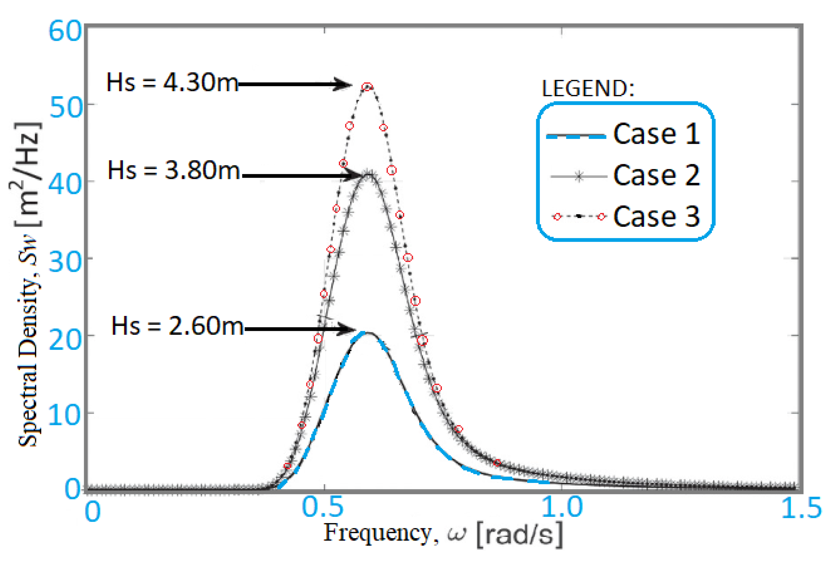
Figure 1. An experimental test showing some sensors attached to a GFRP composite pipe sample for monitoring strains under pressure loading (a test was conducted at Lancaster University Engineering Department; Image Credit: Author 1—C.V.A.).
Energies 15 04982 g001
Figure 2. Different types of marine riser systems are considered for benchmarking composite risers.
Energies 15 04982 g002
Figure 3. A fatigue testing rig for composite marine riser showing sensors, cables, and other monitoring devices used (Reprinted/adapted with permission from Ref. [109]. Copyright year: 2014, copyright owner’s name: Prof. Andreas Echtermeyer, NTNU).
Energies 15 04982 g003
Figure 4. Different monitoring systems utilised in an offshore production investigation, showing submarine buoy monitoring systems, ocean submersible monitoring systems, remotely operated vehicle (ROV), ice mass-balance buoy (IMB), Conductivity-temperature-depth (CTD) instrument, air–sea exchange flux monitoring systems, Ocean Monitoring System (OMS), etc. (Reprinted/adapted with permission from Ref. [131]. Copyright year: 2018, copyright owner’s name: Keia Publishers & China Geology Journal).
Energies 15 04982 g004
Figure 5. The MAPS-FR probe on a pipe sample (Reprinted/adapted with permission from Ref. [132]. Copyright year: 2010, copyright owner’s name: Springer Nature).
Energies 15 04982 g005
Figure 6. Delamination region to visualise failure on the ply when the Ultrasonic C-Scan inspection plot is zoomed (Reprinted/adapted with permission from Ref. [60]. Copyright year: 2016, copyright owner’s name: UPM, NDT & Patricia F. Díaz-Maroto).
Energies 15 04982 g006
Figure 7. The result after the impact of 6.8 J shows the strain map (Reprinted/adapted with permission from Ref. [60]. Copyright year: 2016, copyright owner’s name: UPM, NDT & Patricia F. Díaz-Maroto).
Energies 15 04982 g007
Figure 8. Schematic showing marine risers and mooring lines on a floating platform. The green lines are steel catenary risers (SCR), the black dash straight lines are top-tensioned risers (TTR) while the red lines are mooring lines.
Energies 15 04982 g008
Figure 9. Typical wave data on the JONSWAP spectra.
Energies 15 04982 g009
Figure 10. Wave–current interaction and vortex-induced vibration and motion response on a floating buoy as a typical floating structure.
Energies 15 04982 g010
Figure 11. Illustration of flow patterns and vortex effect around a platform from CFD study in ANSYS Fluent R19.2, showing the Velocity Contour profile.
Energies 15 04982 g011
Figure 12. An experimental model in the Lancaster University wave tank facility showing a floating buoy with wave gauges for monitoring the wave forms and position of the buoy.
Energies 15 04982 g012
Figure 13. The AKASO EK7000 camera utilised in the experiment with its part labelled. It is used to monitor the motion of water waves against the floating structure inside the wave tank or flume used.
Energies 15 04982 g013
Figure 14. Illustration of the monitoring module attached to the surface controller in the patent for composite riser monitoring devices and methods (Patent No.: US20050100414, Courtesy: Conoco Phillips Company).
Energies 15 04982 g014
Figure 15. Application of fiber optic sensor with an optical strain gauge in the corroded part of a pipe (Reprinted/adapted with permission from Dr. Chris Alexander; Source: Ref. [63]. Copyright year: 2018, copyright owner’s name: ASME & Dr. Chris Alexander).
Energies 15 04982 g015
Figure 16. Typical composite pipe repaired with ComposiSleeveTM sample (Reprinted/adapted with permission from Dr. Chris Alexander; Source: Ref. [63]. Copyright year: 2018, copyright owner’s name: ASME & Dr. Chris Alexander).
Energies 15 04982 g016
Figure 17. Result of Hoop strain against internal pressure using the ComposiSleeveTM sample (Reprinted/adapted with permission from Dr. Chris Alexander; Source: Ref. [63]. Copyright year: 2018, copyright owner’s name: ASME & Dr. Chris Alexander).
Energies 15 04982 g017
Table 1. Typical parameters for waves and environmental conditions.
Case ID.Hs (m)Tz (s)Tp (s)Conditions
12.606.207.95Operation
23.805.108.35Extreme
34.305.709.85Survival
Table 2. Analysis Software for Marine Riser and related ocean engineering facilities.
SoftwareVendorApproachAcademic License Available at:PopularityUsage
Nonlinear FEMFrequency DomainTime DomainLancsUniUTP
OrcaFlexORCINA****Wide
ABAQUSSIMULIA*****Limited
ANSYSANSYS*****Limited
DeepLinesPRINCIPIA ***Limited
ANFLEX--- ***Limited
FreecomMCS *Limited
FlexcomMCS *****Wide
Riflex,MARINTEK *****Limited
SimscaleSIMSCALE ***Limited
SesamDNV ***Limited
OrcalayOrcina ***Limited
PipelayMCS ***Limited
SolidworksDassault Syst.*****Limited
MathcadMATHSOFT ****Limited
MatLabMATHWORKS*****Limited
PVIPegasus Vertex *Limited
MOSESBentley ****Wide
DeepCDNV ****Limited
HelicaDNV **Limited
LabViewNational Instru.****Limited
PIPESIMSchlumberger *Limited
OLGASchlumberger *Limited
InventorAutodesk***Limited
VIVANADNV ****Limited
WAMITWAMIT ****Limited
(NOTE: Asterisk (*) is Author’s rating of software’s popularity and usage, ***** is rated highest while * is the least).
Table 3. Industry Standards, Codes and Guidelines on marine hoses, flexible pipes and composite marine risers.
Ref. No. for StandardsTitles and Description
DNV-OS-F101: 2013DNV Offshore Standard: Subsea Pipeline Systems
ABS 2017Guide for Building and Classing subsea riser systems. 3rd ed.
DNV-RP-F202; 2010DNV Recommended Practice: Composite Risers
DNV-OS-F501: 2013, 2010DNV Recommended Practice: Composite Components
API 2INT-MET; 2007Interim Guidance on Hurricane Conditions in the Gulf of Mexico
API Bulletin 16JBulletin on Comparison of Marine Drilling Riser Analyses
API RP 17G; 2011; 2nd Ed.Recommended Practice for Completion/Workover Risers,
API 17J; 2013Specification for unbonded flexible pipe
API 17K, 2017Specification for bonded flexible pipe
API 15S; 2013Qualification of spoolable reinforced plastic line pipe
API RP 2Q, 1984Recommended practice for design and operation of marine drilling riser systems (Been Replaced)
API RP 16Q, 2010Design, selection, operation and maintenance of marine drilling riser systems (To Replace API RP 2Q)
ASTM D4762; 2011Standard guide for testing polymer matrix composite materials
API-RP-2RD 2009 Design of Risers for FPSs and TLPs (errata Ed.)
DNV-OSS-302; 2010DNV Service Specification: Offshore Riser Systems
DNV-OS-F201; 2010DNV Offshore Standard: Dynamic Risers
DNV-RP-F201; 2010DNV Recommended Practice: Design of Titanium Risers
BS 7910:2013 Guide to methods for assessing the acceptability of flaws in metallic structures
DNV-RP-F203; 2010DNV Recommended Practice: Riser Interference
DNV-RP-F204; 2010DNV Recommended Practice: Riser Fatigue
DNV RP C203; 2008Riser Integrity Management: Recommended Practice
DNV RP C203; 2007Environmental conditions and Environmental loads
DNVGL-RP-A203, DNV RP C203Technology Qualification: Recommended Practice
DNV Tech. Rep. 2002-0067DNV Project recommended practice: composite risers, Technical Report Rev. 5
DNVGL-CG-0170: 2015Offshore classification projects—testing and commissioning (To Replace DNV-RP-A205: 2015)
DNVGL-RP-F119; 2015Recommended practice: Thermoplastic composite pipes (TCP)
ISO 13624-1: 2009Part 1: Design and operation of marine drilling riser equipment
ISO 13624-2: 2009Part 2: Deep water drilling riser methodologies, operations, and integrity (technical report)
ISO 13625: 2002Marine drilling riser couplings
ISO 13628-7: 2010 Completion/workover riser system
ISO 13628-10: 2005Part 10: Specification for bonded flexible pipe
ISO 13628-11: 2007Part 11: Flexible pipe systems for subsea and marine applications
MMS Riser Guide; 2010Composite Riser Experience and Design Guidance -Ochoa
RPSEA 1101496; 2014Riser Concept Analysis and Recommendation Report
NORSOK M-001; 2002Norsok Materials Selection Standard
Table 4. Patent list for innovations in monitoring devices with methods for composite risers and steel risers.
Patent No.ReferenceDateTitle of Patent
US20040206187A1Jerry Williams2 October 2007Performance monitoring of offshore petroleum risers using optical strain sensors
US20050100414A1Salama, Mamdouh M.12 May 2005Composite Riser with Integrity Monitoring Apparatus and Method
WO2005047641A1Conocophillips Company26 May 2005Composite Riser with Integrity Monitoring Apparatus and Method
US20040177681A1Harthorn Larry K.16 September 2004Internal riser inspection device and methods of using same
US20050075846A1Hyeung-Yun Kim7 April 2005Methods for monitoring structural health conditions
WO2004111605A3Exxonmobil Upstream Res Co20 October 2005Method and apparatus for fluid flow testing
US20060045408A1Jones Martin P W2 March 2006Structural member bend radius and shape sensor and measurement apparatus
US20060065401A1John Allen30 March 2006System for sensing riser motion
WO2006102259A2Shell Int’le. Research28 September 2006Underwater structure monitoring systems and methods
US7194913B2Shell Oil Company27 March 2007Apparatuses and methods for monitoring stress in steel catenary risers
US20060287842A1Advanced Structure Monitoring, Inc.21 December 2006Methods of networking interrogation devices for structural conditions
US20070012111A1Advanced Structure Monitoring, Inc.18 January 2007Interrogation network patches for active monitoring of structural health conditions
US20070112515A1Gauthier Leo R Jr17 May 2007Light-speed hitpoint sensor
US20070266788A1Hyeung-Yun Kim22 November 2007Diagnostic systems of optical fiber coil sensors for structural health monitoring
WO2008020240A1Insensys Limited21 February 2008Fibre optic sensors
US20080148853A1Hyeung-Yun Kim26 June 2008Gas tank having usage monitoring system
US7536912B2Hyeung-Yun Kim26 May 2009Flexible diagnostic patches for structural health monitoring
US20090157358A1Hyeung-Yun Kim18 June 2009System for diagnosing and monitoring structural health conditions
WO2009087371A1Services Petroliers Schlumberger16 July 2009Monitoring system for pipelines or risers in floating production installations
US20040206187A1Jerry Williams21 October 2004Performance monitoring of offshore petroleum risers using optical strain sensors
US10488296B2Axel Sundermann26 November 2019Method of determining stress variations over time in an undersea pipe for transporting fluids
US20060233485A1Donald Allen19 October 2006Underwater structure monitoring systems and methods
US7461561B2Denby Grey Morrison, Jeremy R. Dean9 December 2008Apparatuses and methods for monitoring stress in steel catenary risers
US6999641B2Jerry Gene Williams, David Barton Smith, Jeffrey David Muhs14 February 2006Measurement of large strains in ropes using plastic optical fibers
US7781725B2; US20050082467A1Guy E. Mossman24 August 2010; 21 April 2005Optical fiber based sensor system suitable for monitoring remote aqueous infiltration
US8520195B2Ramos R.T., Strong A., Lees G.27 August 2013Method and system for estimating fluid leak flow rates using distributed optical fiber sensors
AU2006236751A1Rambow F.H.K.26 October 2006Method of applying a strain sensor to a cylindrical structure
US7245791B2Rambow F.H.K., Dria D.E., Shuck M.Y.17 July 2007Compaction monitoring system
WO2012136259A1Fabien Ravet11 October 2012Method and assembly for sensing permanent deformation of a structure
WO1993025866A1Edward Eduardovich Tapanes23 December 1993Sensing patches utilising incorporated waveguide sensor
Table 5. Patent list on monitoring devices with methods for composite risers, marine hoses, and flexible pipes.
Patent No.ReferenceDateTitle of Patent
US9915579B1David V. Brower13 March 2018Apparatus, system and sensor housing assembly utilizing fiber optic sensors for enabling monitoring operating conditions within a structural member
US9719309B2David V. Brower1 Augu 2017Instrumented strakes and fairings for subsea riser and pipeline monitoring
WO2005064300A1Magne S., Ferdinand P., Pierre-Jean Daniel14 July 2005Instrumented tubular device for the transport of a pressurised fluid using bragg grating rosettes
US7703331B2Magne S., Ferdinand P., Pierre-Jean Daniel13 December 2007Instrumented tabular device for transporting a pressurized fluid
US10054516B2USA & NASA21 August 2018System and method for optical frequency domain reflectometer
US9250120B2Russell James Smith, Andrew Strong, Gareth P Lees2 February 2016Fiber-optic monitoring cable
US8973434B2Shell Oil Company10 March 2015Monitoring system for well casing
US9927263B2The Penn State Research Foundation27 March 2018Intrusion detection system for an undersea environment
US8789585B2Schlumberger Tech. Co.29 July 2014Cable monitoring in coiled tubing
US20180136017A1Lloyd’s Register Americas, Inc.17 May 2018Integration of fiber optic sensors into sleeve
GB2522709AAquaterra Energy Ltd.5 August 2015An offshore pipe monitoring system
US6913079B2Paulo S. Tubel5 July 2005Method and system for monitoring smart structures utilizing distributed optical sensors
US5182779ALtv Aerospace and Defense Company26 January 1993Device, system and process for detecting tensile loads on a rope having an optical fiber incorporated therein
US6865194B1Cidra Corporation8 March 2005Strain-isolated Bragg grating temperature sensor
EP2128571B1Daniele InaudiMarco BossiAntonio Barletta23 July 2014Fiberoptic strain sensor with distributed strain coupling
US20110088910A1Mccann Dominic21 April 2011Monitoring system for pipelines or risers in floating production installations
US10168253B2Liu S., Guzzo J.A., Carbone J.W., et al.1 January 2019Marine riser management system including subsea acoustic monitoring platform and an associated method
US7793726B2Jeremiah DanielJames E. DaileyRuxin Song14 September 2010Marine riser system
US5908049AWilliams, J.G., Sas-Jaworsky, A.,1 June 1999Spoolable composite tubular member with energy conductors.
WO2013037002A1Woodside Energy Tech.21 March 2013Redeployable subsea manifold-riser system
US9784041B2National Oilwell Varco10 October 2017Drilling rig riser identification apparatus
US7798233B2Chevron U.S.A. Inc.21 September 2010Overpressure protection device
US3769127AGoldsworthy W., Hardesty E.20 October 1973Method and apparatus for producing filament reinforced tubular products on a continuous basis.
US5520422ARalph Friedrich, Ming Kuo, Kevin Smyth24 October 1994High-pressure fiber reinforced composite pipe joint
US8656961B2Chen, B.25 February 2014Composite flexible pipe and method of manufacture.
Publisher’s Note: MDPI stays neutral with regard to jurisdictional claims in published maps and institutional affiliations.

