Review

Grid-Forming Converters for Stability Issues in Future Power Grids

Department of Electrical and Computer Engineering, University of Michigan-Dearborn, Dearborn, MI 48128, USA
*
Authors to whom correspondence should be addressed.
Energies 2022, 15(14), 4937; https://doi.org/10.3390/en15144937
Submission received: 23 June 2022 / Revised: 28 June 2022 / Accepted: 30 June 2022 / Published: 6 July 2022

Abstract

:
Historically, the power system has relied on synchronous generators (SGs) to provide inertia and maintain grid stability. However, because of the increased integration of power-electronics-interfaced renewable energy sources, the grid’s stability has been challenged in the last decade due to a lack of inertia. Currently, the system predominantly uses grid-following (GFL) converters, built on the assumption that inertial sources regulate the system stability. Such an assumption does not hold for the low-inertia grids of the future. Grid-forming (GFM) converters, which mimic the traditional synchronous machinery’s functionalities, have been identified as a potential solution to support the low-inertia grids. The performance analysis of GFM converters for small-signal instability can be found in the literature, but large-signal instability is still an open research question. Moreover, various topologies and configurations of GFM converters have been proposed. Still, no comparative study combining all GFC configurations from the perspective of large-signal stability issues can be found. This paper combines and compares all the existing GFM control schemes from the perspective of large-signal stability issues to pave the way for future research and development of GFM converters for large-signal stability analysis and stabilization of the future low-inertia grids.

Graphical Abstract

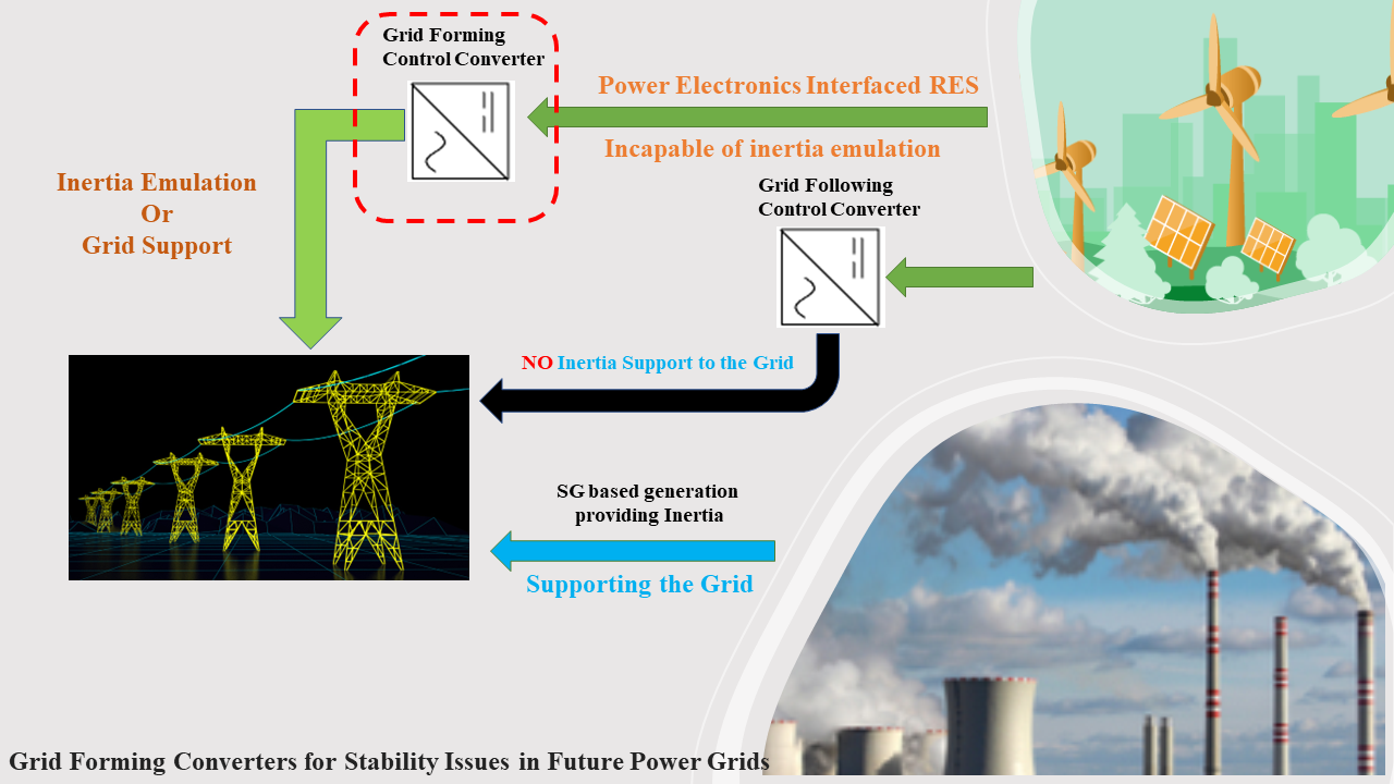
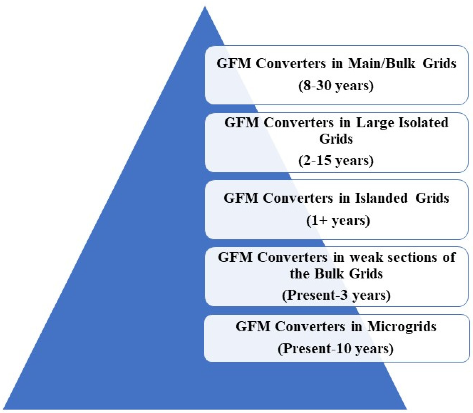
1. Introduction and Literature Review

Technological advancements aided by the motivation to harness clean energy have led power systems to undergo a paradigm shift from conventional synchronous generation methods to power-electronics-interfaced generation. Today’s power grid is transitioning toward having an increasing proportion of generation from non-conventional energy sources, such as solar and wind. The future power system will be a power converter-dominated one [1]. These renewable energy sources (RES) are integrated into the grid through power electronic converters. One of the challenges of this transition from synchronous generation (SG) to a power-electronics-converter-dominated system is the reduction in the amount of rotational inertia in the power system.
The low-inertia system comes with a whole set of critical stability challenges [2]. In addition to the generation side, power converters are constantly increasing on the demand side (consumer electronics, motor drives, EV chargers, etc.) and the transmission side (high-voltage direct current (HVDC) transmission links) [3]. Countries are constantly aiming and planning to increase the share of RES in their system. Europe is a general example of how fast the transition toward RES is occurring. Denmark is an extreme example, where renewable energy has reached 67% of the total electric supply [4]. According to the climate act passed by the Danish government, the target is to reduce greenhouse emissions by 70% by 2030 and to achieve the extreme goal of climate neutrality by 2050. Similar examples and efforts can be found across Europe, America, China, Australia, etc. It can be projected that the share of converter-interfaced generation in the coming decade may cross 70% for some regions where the adoption of RES is at pace [5]. So, it is evident that the future power system will be converter-dominated for those regions. To realize a 100% RES-based grid or converter-dominated system, the problem of low inertia needs to be solved.
Recent projects, reports, and scientific studies have highlighted that the issues of frequency stability in the AC grid and voltage stability in the DC grid are rooted in the low-inertia problem. The Electricity Reliability Council of Texas (ERCOT) reported a continuous decline in the inertial system response [6,7]. Figure 1 shows the inertia box plots for 2013–2018 and the minimum inertia hour of each year. The colored circle at the bottom of each whisker indicates the system inertia during the hour when RES served the highest share of the load. In 2018, the share of RES reached its highest value of 57.87%. The minimum inertia recorded was 129 GWs on one night in November 2018, as presented in Table 1. However, the lowest recorded inertia value is still 30% higher than the ERCOT’s critical inertia value of 100 GWs. Below the critical value, the existing stability responses and mechanisms would not be enough to keep the system stable during a disturbing event [8].
It should be noted that Figure 1 and Table 1 are interrelated. Table 1 explains the data represented in Figure 1. The red line represents the median for each box and the blue box edges represent the 25th and 75th percentiles. Assuming the data are normally distributed, the whiskers represent +/−0.7 (representing 99.3% coverage). It should be noted that the Texas grid (ERCOT) in the United States is one of the three main grids with the minimum size. Its size and the greater penetration of wind energy have required it to opt for solutions such as fast frequency response to handle the problem of declining inertia.
Similarly, the United Kingdom’s national grid also faces the challenge of low inertia. On 9 August 2019, there were blackouts across the UK due to insufficient inertia on the grid. The System Operability Framework report confirms that there has been a continuous decrease in the total system inertia, as shown in Figure 2, and this trend is projected to continue unless some disruptive solution is applied [9].
Grid-forming (GFM) converters are sought as a potential solution for RES integration to overcome the stability issues in the weak inertial system compared to the traditionally used grid-following (GFL) converters. By using a phase-locked loop (PLL) grid-following converters regulates their output. It is important to note that the PLL negatively impacts grid stability [10]. Hence, GFL converters cannot control their output frequency. Comparatively, grid-forming converters can actively control their frequency and voltage outputs, providing grid-forming services [11]. Evidence from the literature shows that the GFM converters support the stability and dynamics of a converter-dominated grid [12]. Moreover, GFM converters have superior abilities, such as enhanced synchronization in weak systems, black start capability, and rate of change of frequency (RoCoF) capability.
The literature shows that the various configurations of grid-forming converters, such as droop control, synchronverter, matching control, virtual oscillator control, direct voltage (V-f) control, and partial grid forming, have been developed over the past decade [13]. The fundamental idea behind the implementation of the GFM converter is to operate it in a similar manner to the operation of a synchronous generator (SG). In [14,15], for the power synchronization of a converter connected to a weak grid system the droop control mechanism is used. The P-f droop control operates similar to a SG in a way that the frequency is reduced when the active power increases. Similarly, for Q-V droop control strategy when there is an increase in the reactive power, the voltage is reduced [16,17]. However, the issue of the lack of inertia persists in the droop control strategies. To improve this, the concept of the synchronverter, was proposed in [18] to emulate inertia. It is also known as a virtual synchronous generator (VSG). The self-synchronized synchronverter is an example of the efforts made to improve further the GFM converters’ fundamental idea [19]. Matching control is based on similarities between the SG and the inverters [20]. Unlike matching control, the virtual oscillator uses droop functions to regulate the output voltage [21]. Parallel inverters are utilized to realize partial grid-forming control [22]. These GFM converters will be discussed in detail later in this paper.
GFM converters are applied for non-traditional grids that lack traditional synchronous generation, which gives rise to modern challenges, such as high grid impedance, lower short-circuit ratio, and lower inertia.
This paper is focused on the stability challenges in non-traditional power grids to leverage the superior performance of GFM converters for stability issues. Significant research efforts can be found on the small-signal disturbances issue [23,24,25]. Small-signal stability criteria can be defined and assessed by linearizing the converter. It can be linearized around an equilibrium point. Various methods have been developed for the small-signal estimation and assessment criteria [26]. In [27], the small-signal analysis and parametric designs for a VSG have been discussed. Robust small-signal stability exists for the GFM converters in weak power grids [28].
A small-signal analysis is not enough or acceptable for large-signal disturbances, such as losing a generation unit, a voltage sag, a fault in the transmission line or a large voltage swing, due to the change of the operating point [28]. So, the large-signal stability leveraging the performance of GFM converters in a non-traditional grid is an open research problem. This paper aims to initiate and analyze all the possible research and technical options that can pave the way for achieving large-signal stability using GFM converters for modern and future grids. Recently, due to the maturation and superior performance of GFM converters, researchers are trying to formulate and define a large-signal stability criterion for such grids. The transient analysis of a droop control for a voltage source converter can be found in [29,30]. The transient behavior under various fault scenarios for a VSC with power synchronization control is presented in [31]. To analyze the large-signal stability of the converters, the equal area criteria (EAC) was proposed in [32,33]. However, EAC is not a good choice for a system containing negative damping. Using EAC for a system with negative damping will affect the system stability determination. In [34], a reduced non-linear model was used for the transient analysis of a converter. Solving the non-linear model equations is a challenge. To overcome the lack of analysis methods, Ref. [35] presented the transient behavior of the voltage source converter. It analyses the energy function of the SG and its stability. It is important to mention that a GFM converter will operate in the voltage source mode under normal conditions. However, it will saturate and change into the current source mode when subjected to a large disturbance. Thus, both modes must be understood and explored for a comprehensive stability study. In [36], it is proved that the non-inertial GFM converters have strong transient stability compared to the inertial control converters. However, the drawback of using non-inertial converters is the lack of inertia, the effects of which are discussed at the start of this paper. Hence, inertial control converters with enhanced transient stability are the only solution for future power grids. The phase portrait method demonstrates the inertial and non-inertial GFM control in terms of stability [37]. The alternative virtual inertia optimization approach is suggested in [38,39] to enhance transient stability and dynamic performance. In [40], a method to maintain stability without the set equilibrium points is presented by switching the positive feedback to the negative feedback of the power angle.
It is to be noted that these methods, based on the difference ( δ ) , are applicable and tested for strong power grids. These methods are not applicable for low-inertia grids, which is our focus in this paper. For converter-dominated grids, the phase angle δ is approximately constant. Significant research needs to be conducted to extend and modify these identified methods for the low-inertia grids. The center of inertia (COI) concept was proposed to solve this issue for low-inertia grids [41]. The concept of the switching control method states that the GFM control should switch to GFL control to ensure system stability in an event of a severe disturbance [42].
Another problem that arises is the saturation of the current limiters. One solution is the virtual impedance-based voltage limiting strategy. To reduce the AC voltage reference in the case when the current exceeds the threshold, a virtual output impedance is added [43]. However, a constant virtual impedance does not apply to all types of faults. The selection of the virtual impedance depends on the fault type and location; hence, more research can be performed to formulate an adaptive method. Table 2 provides the overview of major existing issues for the power converters. The ranking is based on the authors extensive research survey and in the guidance of various reports from all the stake holders in this domain.
This paper contributes toward the comprehensive literature review of all the existing large-signal stability techniques for a low-inertia grid, analysis, and comparison of all the grid-forming converters topologies to date, and identification of the potential research questions that need to be researched for the realization of the futuristic renewable sources dominated/low-inertia grid. The paper is structured as follows:
Section I forms the basis through the introduction and background knowledge to help the reader to understand the importance of and need to address the identified research gap. Moreover, it provides an extensive literature review of the existing transient stability techniques and GFM converters and highlights the drawbacks of each method. It also identifies the potential areas where the existing strategies can be improved or extended to make them applicable for the futuristic low-inertia grids.

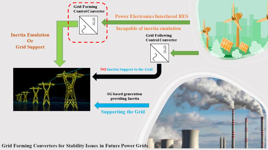
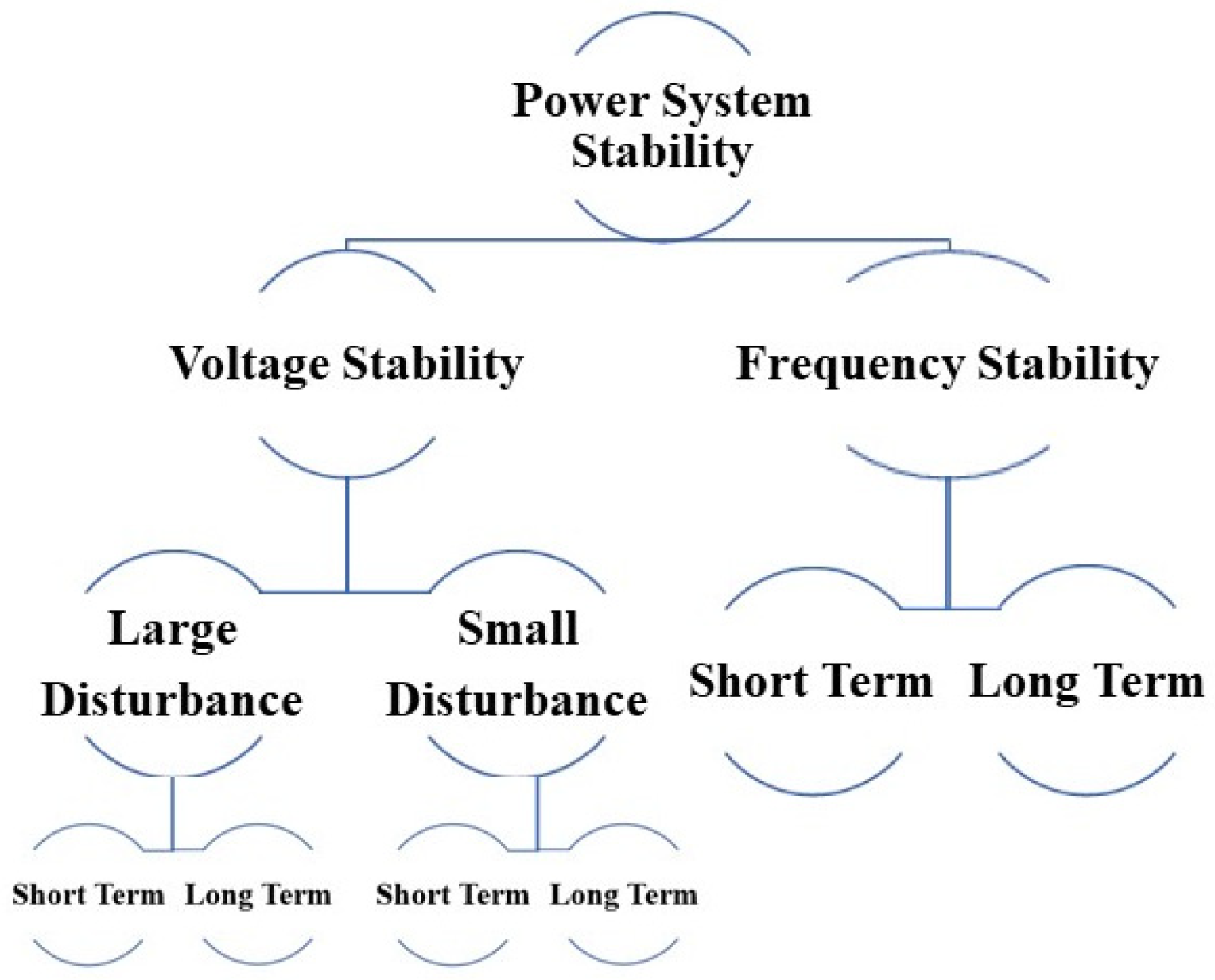
2. Grid-Forming Converters and Power System Stability

Grid-forming (GFM) converters, a relatively new concept, cannot be readily implemented into the bulk grid system. Significant research and reliability tests for a more extended period are required before commissioning them into the bulk grids. Microgrids and island grids are a good starting point to mature and test the GFM technology. Figure 3 shows the grid-forming converters’ multi-year research and implementation road map [44].
It is not wise and economically feasible to replace all existing predominantly GFL converters with grid-forming controls. The near-future power system will involve a mix of grid-following and grid-forming controls. The growth and performance of GFM converters over time will determine the speed of recognition as the penetration of RES increases. It also means that before reaching the goal of a 100% renewable energy-based grid, there will be a mixed/hybrid grid containing both traditional generators and power electronics-interfaced generation (RES). The power system stability can be analyzed and assessed through the system performance under frequency control, voltage control, and fault protection [45]. Figure 4 provides the classification of the power system stability criteria.

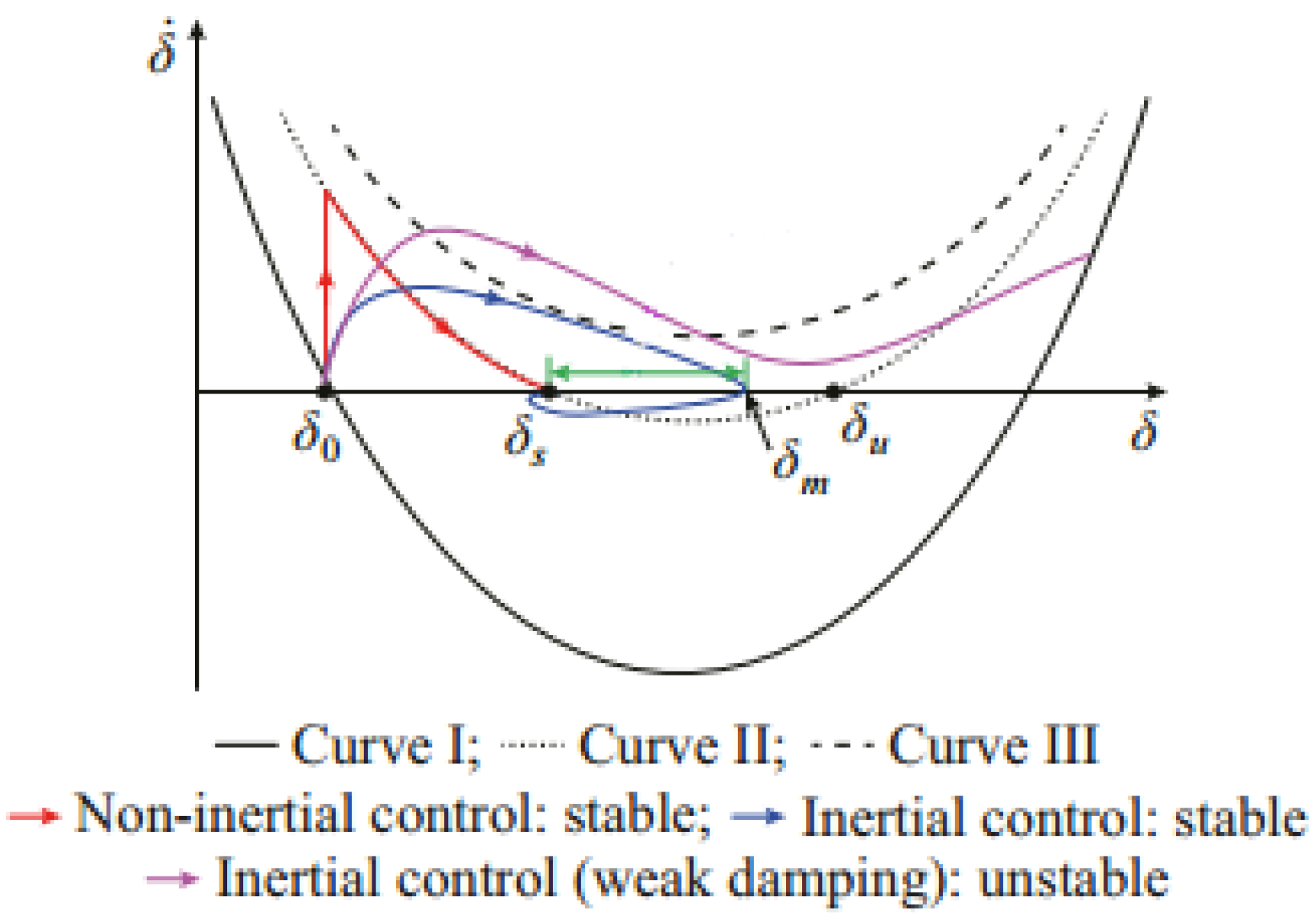
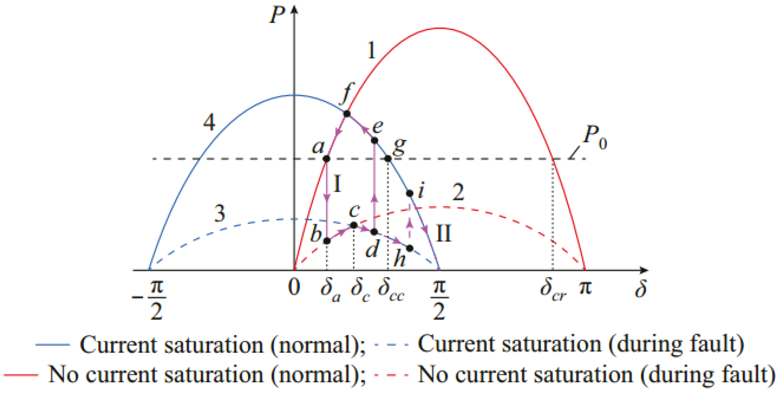
2.1. Large-Signal Stability Issues

In the case of a large-signal disturbance, such as a 3-phase AC fault, the GFM converter faces overcurrent problems; thus, current limiting strategies are necessary for safe operation. The two major fault-limiting strategies found in the literature include the instantaneous saturation limiter and latched limiter [46]. Due to the large-signal disturbance, the GFM converter’s operation mode switches from voltage source to current source mode. Both modes need exploration for the comprehensive analysis and understanding of large-signal stability.
The converter’s current should not exceed the limits for the GFM converter to stay in the voltage source mode. This is possible in the case of a low or less severe fault. The power loop of the inertia-providing GFM converter is a second-order system. It can produce power oscillations when no sufficient damping is provided, and as a result, the stability performance of the GFM converters is affected [47]. In [48,49], the stability of the inertial GFM control is analyzed using the phase portrait method, as shown in Figure 5. Under normal operating conditions, the equilibrium point is set at δ o on curve I; in the case of a slight fault, the operation shifts to curve II at point δ s . Due to the inertial nature (second order) of the GFM converter, the operating point and trajectory of the curve deviate from curve II. This phenomenon, aided by the weak damping system, causes the inertial GFM controller to lose stability, even if a stable equilibrium point exists at δ . Thus, non-inertial control has a greater stability performance. Still, due to the lack of inertia, it is not applicable to the future l ow-inertia grids, where inertia-emulating converters are in scope.
Due to the saturation of the current limiter in the case of a severe fault, the converter shifts to the current source mode. Transient stability analysis in the current source mode is performed using the virtual power angle curve [50], as shown in Figure 6.
For curves 1 and 2, the GFM converter operates in the voltage source mode. Curves 3 and 4 correspond to the scenario in which the GFM converter switches to the current source mode due to a severe fault. The next event is the current limiter saturation. Under normal circumstances, the operating point is set on curve 1. In the case of a fault, the operating point shifts to b and then to c on curve 2, following the power imbalance. The saturation of the current limiter at point c leads to the shifting of the GFM converter to the current source mode. The operating point shifts to curve 3 due to the increase in the angle. The operating point would go to point e if the fault is cleared before reaching the critical clearing angle δ c c , and then finally reach the normal operating point a. The operating point will keep moving on curve 2 and eventually lose synchronization if the fault is not cleared before reaching δ c c . To solve these stability problems, various methods have been proposed, such as a shifting control method [52], in which the GFM converter switches to GFL control mode in the case of a fault. In [53], the virtual impedance-based voltage-limiting method was implemented. In this method, an output impedance is added to lower the reference voltage when the current goes beyond the allowable limits. This helps the current reference to decrease and avoid saturation. The power angle curve is modified in [54] to satisfy the equal area criteria and ensure that the equilibrium points still exist under faulty conditions. To understand the stability dynamics in-depth, specific stabilities, such as frequency and voltage stability, need to be understood.

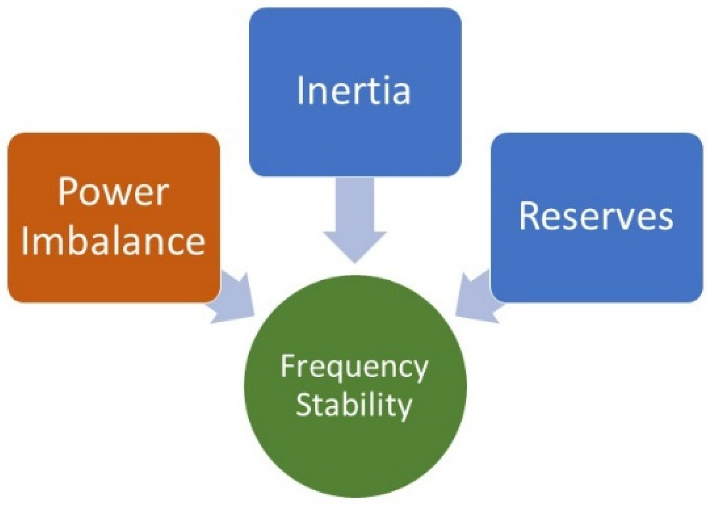
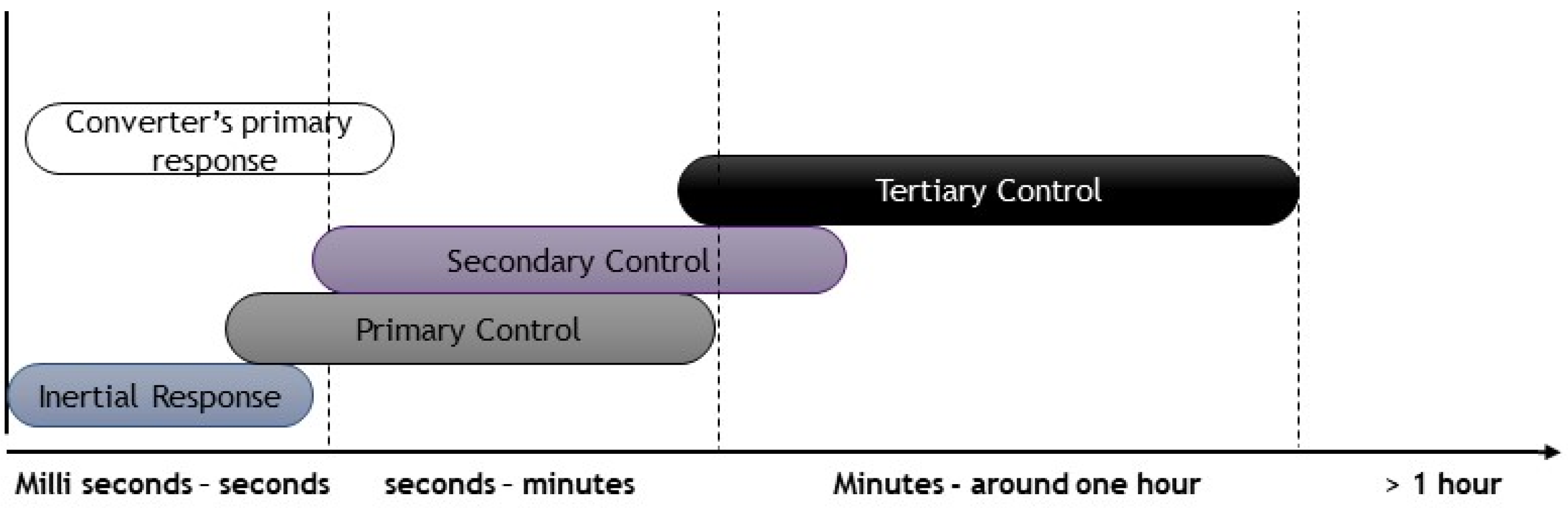
2.2. Frequency Stability

The frequency stability or control objective is to keep/regulate the frequency at the nominal or set value. The major indicators for monitoring and control are the rate of change of frequency (RoCoF) and frequency nadir. The contex of low-inertia grids leads to a higher RoCoF, and the frequency nadir falls outside the allowable limits. The addition of the rotational mass to the grid is directly proportional to the inertia emulation and increased damping. For converter-based renewable energy generation, the risk of high-frequency swings can be mitigated by GFM converter controls, which provide the inertial response and the primary frequency control by detecting the frequency swing and adjusting the power injection to maintain the nominal value [55]. Factors affecting the system stability are highlighted in Figure 7.
To achieve a faster frequency control action after a large disturbance, a headroom or reserved capacity must be in place to mitigate the generation and the load imbalance. After disturbance, the frequency swing magnitude depends on the power imbalance. For inverter-interfaced sources, the reserve capacity can be obtained through inverter interfaced batteries or by operating the inverter at a value less than the rated value. The drawback is the unused capacity and the associated cost. It is to be noted that for large frequency deviations in low inertia, the primary control based on the spinning or mechanical reserves may not be fast enough [56]. So, fast-acting devices, such as converters, are the most suitable option for low-inertia grids. Figure 8 shows the control and response scheme associated with frequency dynamics and control. The rotation of the rotor provides the inertial response immediately for synchronous machines, while for a converter-dominated system, the inertial response is provided with a little bit of delay. After that, the primary, secondary, and tertiary controls take over. A faster primary frequency response than the conventional plants can be generated using power converters. Power converters, in general, have a fast response time. The challenge at hand is the inability of power converters to respond to natural power imbalances. This risk is in the first few milliseconds of the disturbance timescale. Due to the stochastic nature of RES, another challenge is ensuring and guaranteeing a given reserve and security.
Multiple techniques can be realized considering frequency stability in the context of grid-forming controls. All GFM controls adhere to the p-f steady-state droop law through which the steady-state frequency deviations are controlled. Compared with the traditional grids, the established hierarchical control methods for inverter-interfaced microgrids are somewhat similar to the hierarchical control strategies. P-f droop slope can be used for each inverter’s primary response. The schemes having low bandwidth communication requirements have been used for secondary and tertiary response mechanisms [57,58]. These techniques used on droop inverters can be applied to the grid-forming inverters. The lack of matured and applied grid forming solutions holds back the hierarchical control strategies in microgrids and bulk systems. The steady-state response of all the GFM control methods is almost identical; however, their dynamic response is different. The specific dynamic behavior of each GFM converter topology is discussed in the next section. The following research questions need further investigation to realize GFM converters in low-inertia grids on the bulk level that can regulate frequency during a large disturbance:
  • Should the grid-forming controls be categorized similarly to hierarchical controls based on time scale?
  • Considering the stochastic nature of RES, new dynamic models need to be derived to guarantee the system reserve and security margin.
  • GFM-controlled sources can generate a fast frequency response when storage reserves are made available. What is the optimal placement amount and location of these reserves?
  • Do the maximum and minimum frequency limits need to be changed for a low-inertia or converter-dominated grid?
  • Does the simultaneous operation of the GFM, GFL, and SG improve the system stability or worsen it?
  • What is each regulator’s optimal and maximum allowable share, such as GFL or GFM?
  • How can the nature of RES (such as PV and wind) impact the frequency regulation for a GFM-controlled converter?

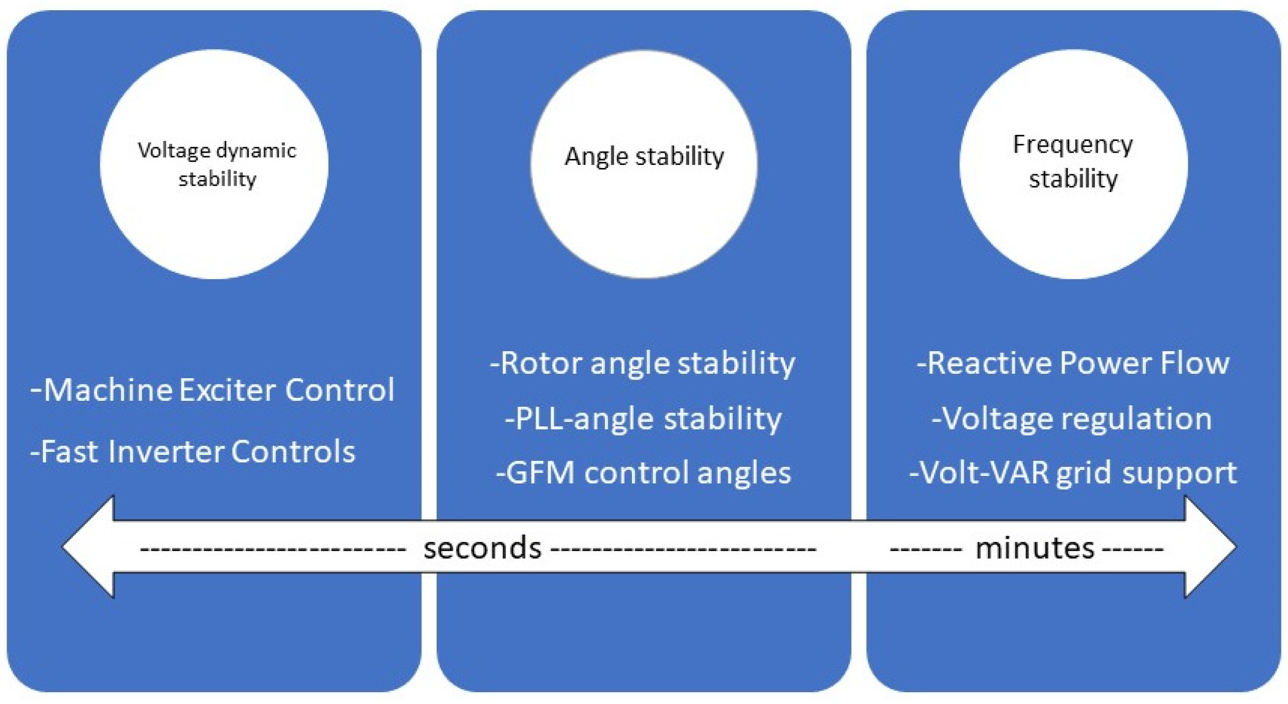
2.3. Voltage Stability

Voltage stability can be understood as keeping the system voltage within the acceptable range. Dynamic voltage stability issues are experienced by the exisiting GFL converters in low-inertia grids. Recently, the case of voltage stability issues was reported by ERCOT, where the voltage at the 230 KV system dropped in a weak grid [59]. The principal reason behind such stability problems is the voltage reduction when the power order increases at the PCC. This coupling is due to the GFL control architecture aided by the weak inertial grid conditions. The short-circuit ratio (SCR) defines the grid strength, which is 1 X g ,   where   X g is the line reactance. If SCR < 3, it refers to a weak grid [60]. The system’s GFL control depends on the grid for voltage and frequency regulation. According to the NREL’s report on GFM converters, GFM converters are considered the only feasible and potential option that can provide frequency and voltage support services.
The voltage regulation or control action includes increasing or decreasing real and reactive power. Usually, GFM converters provide voltage control through reactive power due to its enhanced sensitivity, also known as the Q-V droop control. There is a tradeoff between steady-state voltage and reactive power for GFM converters. A common method used to balance the power control is known as volt–volt ampere reactive (VAR) control. Its functionality can be added to GFL inverters too. So, GFM converters can perform better and provide voltage support in weak inertial grids [61]. The importance of voltage control or stability is enhanced for the developing DC grids. Thus, there have been some advancements in voltage control in microgrids. In [62], virtual impedances have been added to reduce the parameter sensitivity and assist with the reactive power. Communication-based controllers offer low steady-state errors and great power-sharing capability [63]. These approaches apply only to systems where a communication link is possible and with high fault current magnitudes. As the future bulk grids and microgrids would be geographically distributed and the fault current of the GFM converters is not high, these approaches cannot be applied. Specific new approaches and stability criteria are required for the developing systems. Ref. [64] reported adverse effects and responses when GFM converters and synchronous machines were combined for the voltage regulation. Similar issues are also found with the mature GFL converter technology. Such uncertain responses are harmful to a hybrid grid network, and more research needs to be performed to find the root cause and a remedy for this problem. The stability framework includes only frequency, voltage, and rotor angle stability for the traditional power grids. Compared to the classical, the modern and future systems will include more controls and factors, as shown in Figure 9.
Following open research, questions can be formulated regarding voltage regulation.
  • When GFM replaces GFL controls on a large scale, it will shift the reactive power control from a centralized to the local level. How will it affect the system control and stability?
  • How can their interaction be optimized in a hybrid system that includes both machines and GFM inverter-based sources?
  • Will the combination of machines, GFL controls, and GFM controls strengthen or weaken the system’s stability? How can the optimal share of each be identified?
  • How can the input and output impedances of GFM converters be modeled and characterized to improve the system’s overall dynamic response?
  • Investigation of the possible issues in the implementation of VAR controls for GFM converters.

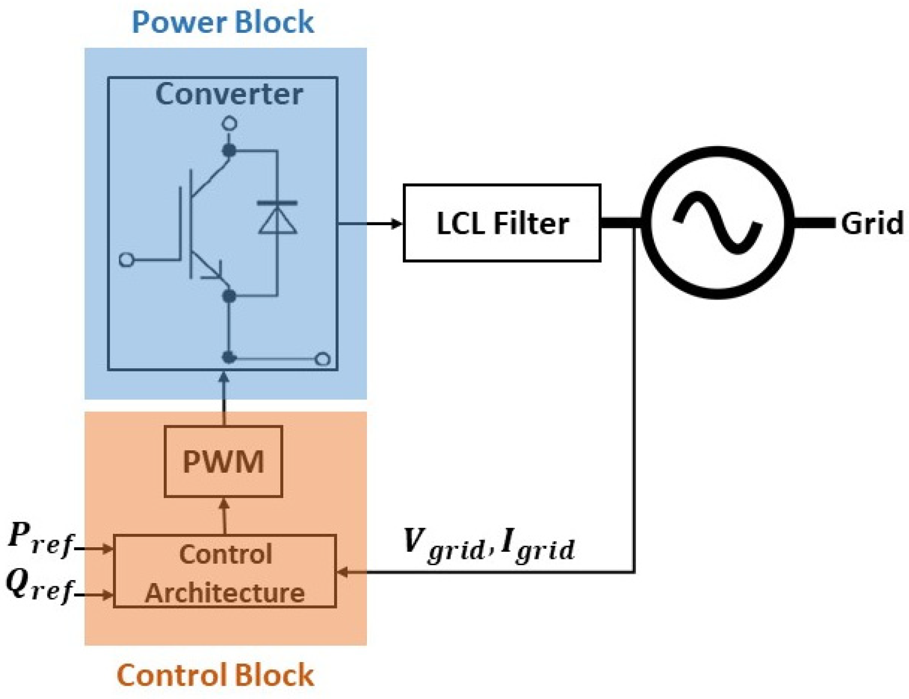
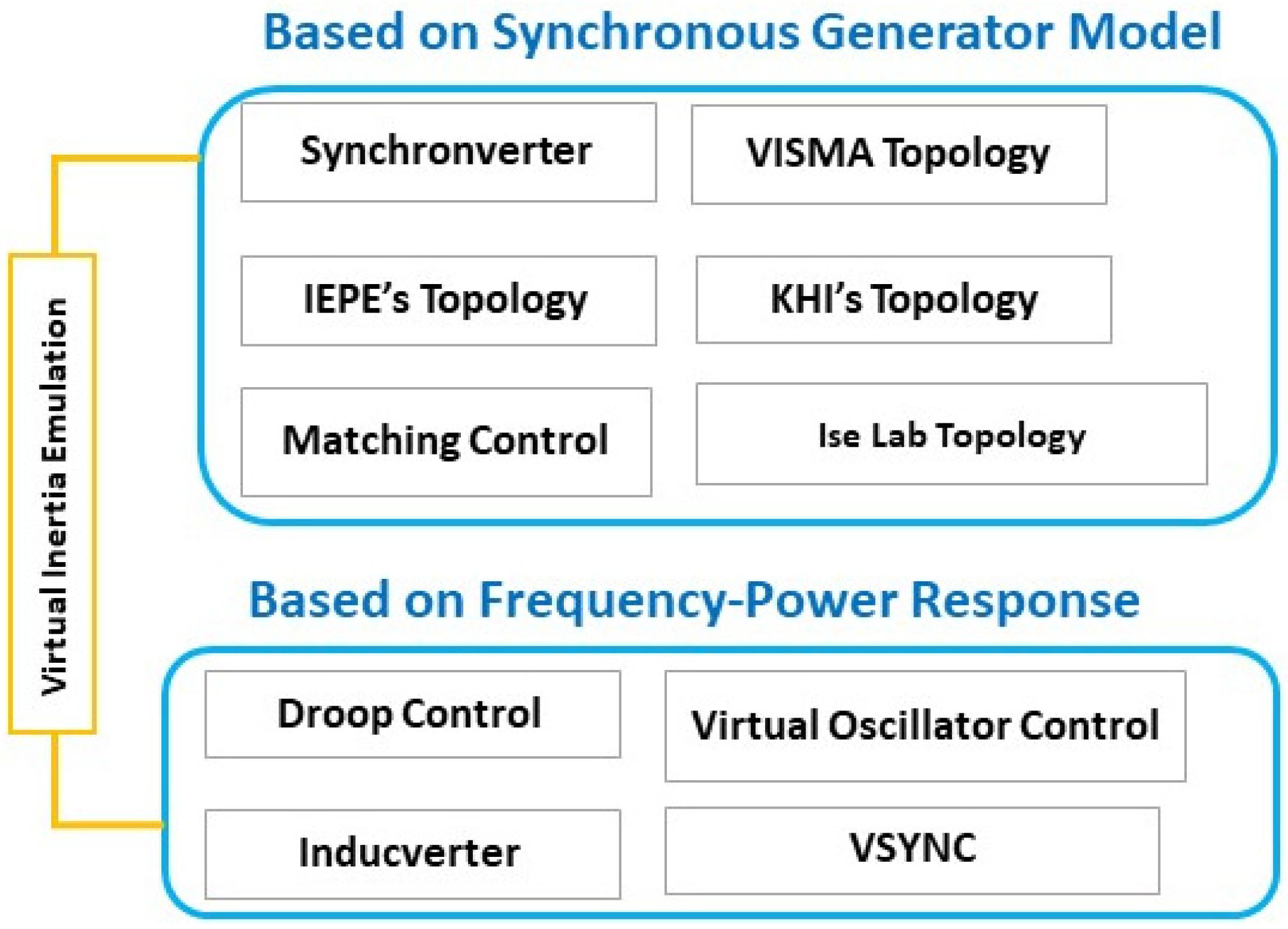
3. Grid-Forming Converters Topologies
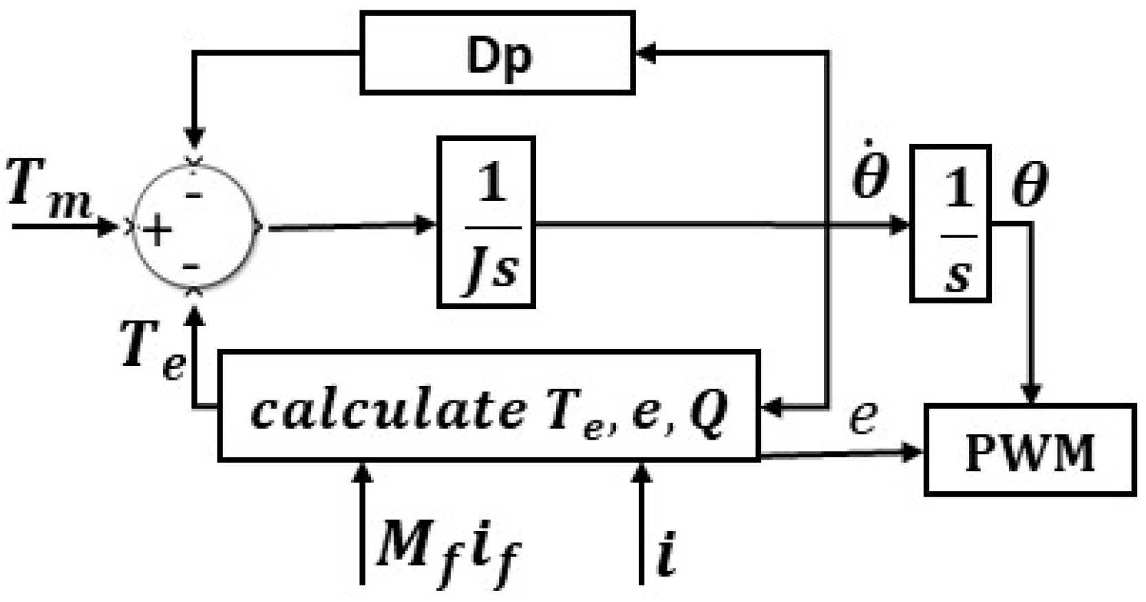
Various topologies and configurations of grid-forming converters can be found in the literature. In [63], GFM converters are classified based on the controller structure. GFM converters have some distinct properties that make them the best for inverter-based grids, apart from providing inertia and strengthening the grid. This includes the independent voltage and frequency control, being able to function as an infinite bus, black start capability, suitability for weak AC grids due to low output impedance, etc. [64]. In this section, GFM converters capable of inertia emulation are discussed.

3.1. Synchronverter

The synchronverter, also known as a virtual synchronous machine (VSM), operates on the principle of the synchronous machine virtually following the famous swing equation shown in Equation (1).
J w ˙ = T m + T d T e
T m = m e c h a n i c a l   T o r q u e ,
T e = E l e c t r i c a l   t o r q u e   i n d u c e d   b y   c u r r e n t ( i t   o p p o s e s   p r i m e   m o v e r )
T d = d r o o p   t o r q u e ,
( T m + T d ) = a c t i v e   t o r q u e   o r   p r i m e   m o v e r   t o r q u e
The synchronverter can be classified into two major blocks, i.e., control and power block. Power block consists on the converter and its interconnection with the grid, while the control block is responsible for the calculation, regulation, and generation of PWM pulses for the gate driver of the converter, as depicted in Figure 10.
T e = M f i f i ,   s i n θ ˜
e = M f i f w   s i n θ ˜
= v q i d v d i q
Here, mechanical inertia is replaced by the power of a DC bus. It also models the other attributes of SG, such as disturbance response and inertia emulation. The unique feature of the synchronverter is that all the parameters of SG are modeled in a synchronverter; thus, all the matured and existing control strategies designed for SG can be applied to a synchronverter [18]. Moreover, it depicts the same dynamics as the SG and can be operated as a synchronous motor, which sets it apart from other machine-emulating methods. A synchronverter can be operated in GFM and GFL mode, as it does not follow a voltage or current reference. In [19], an improved self-synchronized version of synchronverter was proposed. The control architecture of the synchronverter is presented in Figure 11.

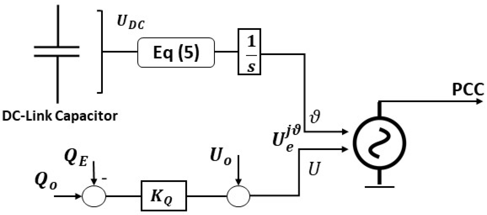
3.2. Matching Control

The structural similarities between the SG and inverter model realize the matching control topology. It controls the DC link, similar to how a mechanical rotor is controlled. The difference between synchronverter and matching control is that, in the latter, to drive the harmonic frequency oscillator, instead of using an SG model, a DC link is utilized. A controller drives the inverter modulation based on the embedded internal oscillator model. To monitor the power balance, the DC link voltage is used. By controlling the DC current, active power tracking can be achieved, which results in the oscillator frequency and voltage control. Matching control only utilizes DC-side measurements which results in no processing delays [65]. In simple words, the duality of the DC voltage of the converter and the machine’s angular velocity can be referred as matching control. It considers the DC-link capacitor as a storage device, similar to the concept of inertia. So, the capacitor voltage is used to regulate the frequency of the converter bridge [66]. The control is depicted in Equation (5):
ω = ω g + s + K T K j s + K D [ ( U D C ) 2 ( U D C r e f ) 2 ]  
where ω is the output frequency, ω g is the grid frequency, and U D C is the voltage of the DC-link capacitor. The control architecture is shown in Figure 12.

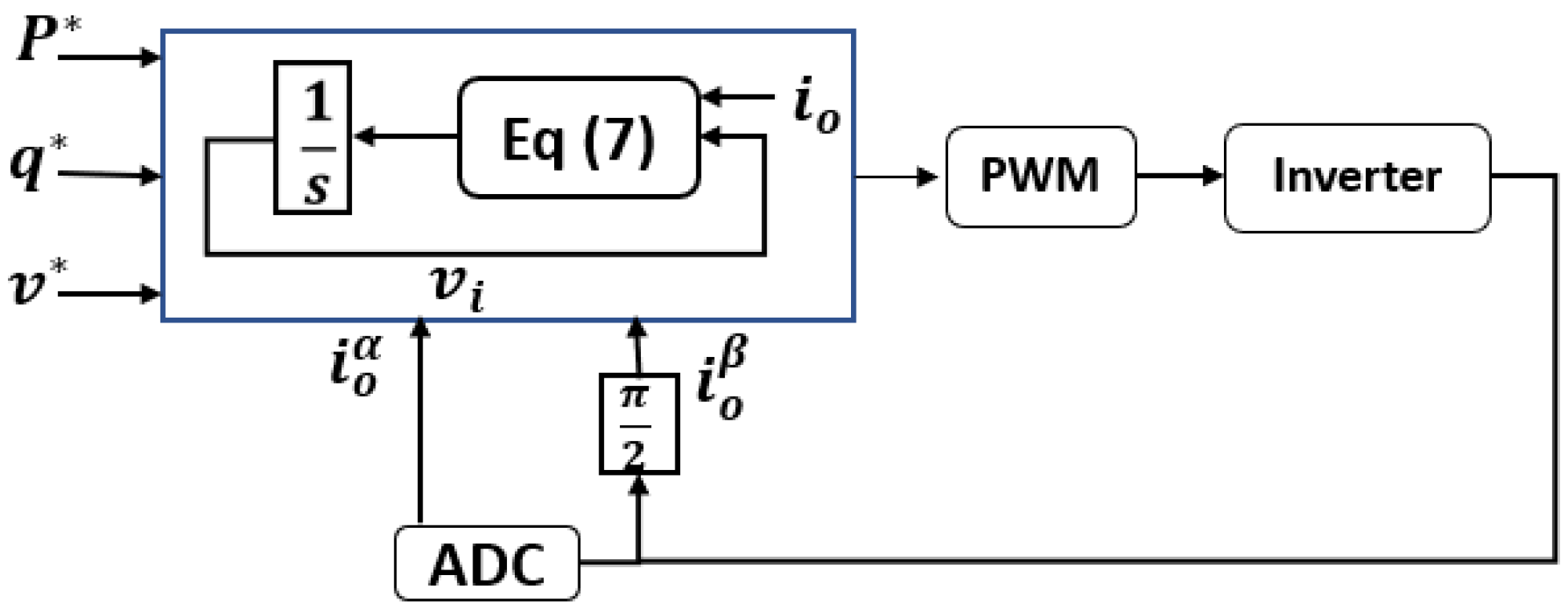
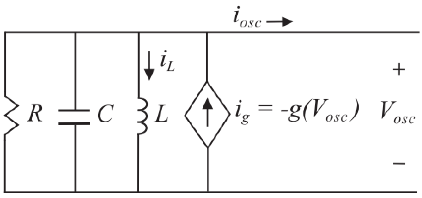
3.3. Virtual Oscillator Control (VOC)

VOC is based on the emulation of the non-linear oscillators’ dynamics in the inverter control. It is much similar to matching control in terms of the emulation of non-linear oscillations’ dynamics. The difference is that, instead of using phasors, the VOC uses time-domain signals for voltage regulation. Understanding the oscillator model is a prerequisite to understanding the VOC approach. The non-linear dead zone oscillator on which the VOC method is based is shown in Figure 13 [67]. The oscillator consists of a resonant LC tank through which the frequency can be set. The non-linear current source helps to sustain the oscillations, and the resistor R acts as a damping element. Most oscillators can be modeled by connecting a passive impedance parallel to a non-linear current source. Figure 13 represents the topological approach for the VOC.
The PWM signals for the converter are generated using the oscillator’s terminal voltage. It is to be noted that the oscillator must operate in the quasi-harmonic region by following Equation (6):
ε = L C ( σ 1 R ) > 0  
The unique characteristics of VOC include possessing all the features of droop control, while providing superior voltage regulation and load-sharing capabilities. The only point that needs attention and further research is the trade-off between frequency deviation and response time for a VOC.

3.4. Dispatchable Virtual Oscillator (dVOC)

Virtual oscillator control provides enhanced performance in dynamic voltage regulation and maintains the droop control law [68], but it is still a mystery how to configure the inverter’s power injections when they lack programmable power setpoints. A good candidate for such a scenario is dVOC.
Dispatchable VOC allows the user to set power setpoints for the inverter. In the case of absent set points, dVOC operates in the VOC mode and provides all the needed functions. v d q is the reference voltage generated, following the control law from Equation (7):
d d t v d q = w r e f J v d q + η ( K v d q R ( k ) i d q + α v r e f 2 ( v r e f 2 v d q 2 ) v d q )  
where R ( k ) is the rotation matrix:
R ( k ) = [ c o s ( k ) s i n ( k ) s i n ( k ) c o s ( k ) ]  
where K is the inductance-to-resistance ratio. η   and   α are virtual oscillator design parameters; ω r e f   and   v r e f are frequency and voltage references, respectively;   i d q is the measured current; and | | v d q | | is the measured voltage magnitude. The control architecture of dVOC is shown in Figure 14. P * ,   q * ,   v * represents the reference values.

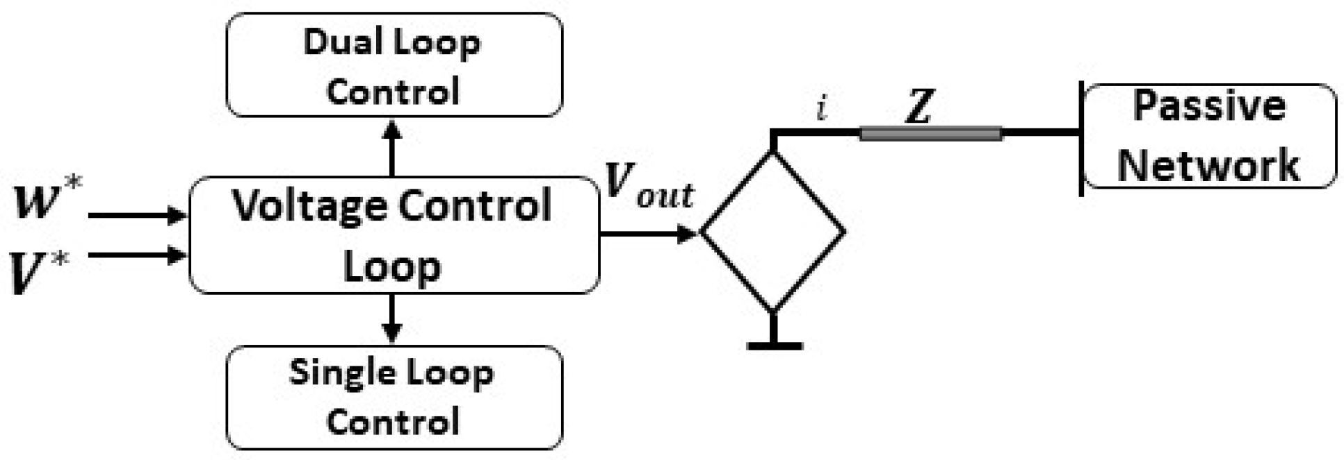
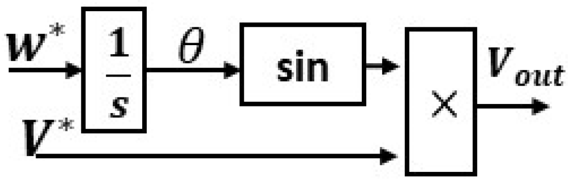
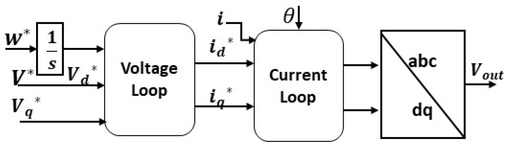
3.5. Direct Voltage (V-f) Control

V-f control is most suitable for passive grid applications, such as uninterruptible power supply and islanded grids because the output voltage and frequency remain under closed-loop control. This GFM technique lacks power-sharing ability. Therefore, it has limitations when applied to active grids. As depicted in Figure 15, V-f control can be presented as a controlled voltage source, having an output impedance in series. W * ,   V * represents the reference values.
V-f control have two modes, i.e., a single or dual-loop control. In the case of single-loop control, the reference value of the frequency and voltage generates the voltage output ( V o u t ) of the converter. For a dual-loop control, the output voltage ( V o u t ) comes through cascaded loops of current and voltage, which give current-limiting ability to dual-loop control. The single loop mode is applied for DC-link voltage control in GFL applications, and it can be used for AC voltage regulation in GFM applications. This control strategy is beneficial when implemented in a master–slave topology. Where multiple GFL converters follow a master or a leader, the leader is a GFM converter. In the case of more than one GFM converter in a network, the phase synchronization angle should be shared amongst all of them via communication channels, which disables this control scheme’s decentralized operation ability. Figure 16 and Figure 17 show both the single and dual-loop control modes.
The unique aspect of the grid forming converters lies in their ability to emulate inertia. Multiple topologies are reported in the literature to date; Figure 18 presents an overview of all the existing and proven virtual inertia emulation topologies. The synchronverter is explained in detail in [18,19]. Refs. [63,64,65,66] presents the matching control and the VOC is presented in [67,68]. The droop control is explained in [69,70]. The VISMA topology can be understood through [71,72]. The IEPE’s topology is presented in [73,74] is focused on KHI’s Topology The Ise topology is presented in [75,76]. The inducverter can be understood through [77] and the VSYNC is explained in [78,79]. GFM techniques can be divided into two categories, i.e., based on the SG model or on frequency power response. Both approaches have pros and cons, so the selection is dependent purely on the application and conditions. For large-signal stability, SG-based models are more promising due to accurate modeling and the mimicking of SG characteristics. The SG-based model enables the accurate emulation of the dynamics; there is no need for PLL (except for synchronization), and it is not dependent on the frequency derivative. The challenges include numerical instability issues, voltage source implementation, and over-current protection.
Frequency power response has a much simpler and straightforward implementation. It has an inherent over current protection and has current source implementation. The drawbacks include instability issues due to the presence of PLL (especially in weak grids). Moreover, it also needs a frequency derivative and is more susceptible to noise.

4. Conclusions

To overcome the stability challenges (especially large-signal stability) in modern/future RES-dominated low-inertia grids, this article provided a comprehensive analysis and investigation into leveraging the superior performance of grid-forming converters to improve the large-signal stability performance. The long- and short-term stability criteria and factors affecting it, along with the converter’s behavior during large-signal instability, were discussed.
A comparative analysis of all the relevant existing grid-forming topologies and their control architectures was presented to enable in-depth understanding for the reader. Moreover, open research questions were identified throughout the paper, which must be extended as a future research problem. In conclusion, this article provided a research roadmap. It built a foundation to utilize GFM converters for the maturation and stabilization of the modern power system by solving the low-inertia and large-signal stability issues.

Funding

This work was supported in part by the U.S. National Science Foundation (NSF) under Award 2034938. Any opinions, findings, conclusions, or recommendations expressed in this material are those of the author(s) and do not necessarily reflect the views of the National Science Foundation.

Institutional Review Board Statement

Ethical approval not required.

Informed Consent Statement

Not applicable.

Data Availability Statement

Not applicable.

Conflicts of Interest

The authors declare no conflict of interest.

References

  1. Monti, A. Low Inertia Grids: Towards a power electronics-based power system. In Proceedings of the 2019 21st European Conference on Power Electronics and Applications (EPE ‘19 ECCE Europe), Genova, Italy, 3–5 September 2019; p. 1. [Google Scholar] [CrossRef]
  2. Milano, F.; Dörfler, F.; Hug, G.; Hill, D.J.; Verbi, G. Foundations and Challenges of Low-Inertia Systems. In Proceedings of the Power Systems Computation Conference (PSCC), Dublin, Ireland, 11–15 June 2018. [Google Scholar]
  3. ENTSOE—System Operation Committee (SOC). One Vision 2030 Internal Report; ENTSOE: Brussels, Belgium, 2019. [Google Scholar]
  4. IEA. Energy Policies of IEA Countries: Denmark 2017 Review; IEA: Paris, France, 2017; Available online: https://www.iea.org/reports/energy-policies-of-iea-countries-denmark-2017-review (accessed on 4 April 2022).
  5. IEA. Global Energy Review 2021; IEA: Paris, France, 2021; Available online: https://www.iea.org/reports/global-energy-review-2021 (accessed on 4 April 2022).
  6. Electricity Reliability Council of Texas (ERCOT). Future Ancillary Services in ERCOT; ERCOT: Austin, TX, USA, 2013. [Google Scholar]
  7. Matevosyan, J.; Sharma, S.; Huang, S.H.; Woodfin, D.; Ragsdale, K.; Moorty, S.; Wattles, P.; Li, W. Proposed future Ancillary Services in Electric Reliability Council of Texas. In Proceedings of the IEEE PowerTech, Eindhoven, The Netherlands, 29 June–2 July 2015; p. 6. [Google Scholar]
  8. Julia Matevosyan-ERCOT. Inertia Trends in ERCOT. 25 February 2020. Available online: https://www.esig.energy/inertia-trends-in-ercot/ (accessed on 2 February 2022).
  9. National Grid ESO. O I NEEE; National Grid ESO: Warwick, UK, 2020. [Google Scholar]
  10. Wen, B.; Boroyevich, D.; Burgos, R.; Mattavelli, P.; Shen, Z. Analysis of dq small-signal impedance of grid-tied inverters. IEEE Trans. Power Electron. 2015, 31, 675–687. [Google Scholar] [CrossRef]
  11. Pattabiraman, D.; Lasseter, R.H.; Jahns, T.M. Comparison of Grid Following and Grid Forming Control for a High Inverter Penetration Power System. In Proceedings of the 2018 IEEE Power & Energy Society General Meeting (PESGM), Portland, OR, USA, 5–10 August 2018; pp. 1–5. [Google Scholar] [CrossRef]
  12. Ackermann, T.; Prevost, T.; Vittal, V.; Roscoe, A.J.; Matevosyan, J.; Miller, N. Paving the Way: A Future Without Inertia Is Closer Than You Think. IEEE Power Energy Mag. 2017, 15, 61–69. [Google Scholar] [CrossRef] [Green Version]
  13. Ray, I. Grid-Forming Converter Control Method to Improve DC-Link Stability in Inverter-Based AC Grids. Ph.D. Thesis, The University of Tennessee, Knoxville, TN, USA, 2021. [Google Scholar]
  14. Zhang, L.; Harnefors, L.; Nee, H.-P. Power-synchronization control of grid-connected voltage-source converters. IEEE Trans. Power Syst. 2010, 25, 809–820. [Google Scholar] [CrossRef]
  15. Zhang, L.; Harnefors, L.; Nee, H.-P. Interconnection of two very weak AC systems by VSC-HVDC links using power-synchronization control. IEEE Trans. Power Syst. 2011, 26, 344–355. [Google Scholar] [CrossRef]
  16. Li, Y.; Vilathgamuwa, D.M.; Loh, P.C. Design, analysis, and realtime testing of a controller for multibus microgrid system. IEEE Trans. Power Electron. 2004, 19, 1195–1204. [Google Scholar] [CrossRef]
  17. Guerrero, J.M.; Vicuna, L.G.; Matas, J.; Castilla, M.; Miret, J. A wireless controller to enhance dynamic performance of parallel inverters in distributed generation systems. IEEE Trans. Power Electron. 2004, 19, 1205–1213. [Google Scholar] [CrossRef]
  18. Zhong, Q.; Weiss, G. Synchronverters: Inverters That Mimic Synchronous Generators. IEEE Trans. Ind. Electron. 2011, 58, 1259–1267. [Google Scholar] [CrossRef]
  19. Zhong, Q.; Nguyen, P.; Ma, Z.; Sheng, W. Self-Synchronized Synchronverters: Inverters without a Dedicated Synchronization Unit. IEEE Trans. Power Electron. 2014, 29, 617–630. [Google Scholar] [CrossRef]
  20. Arghir, C.; Jouini, T.; Dörfler, F. Grid-forming control for power converters based on matching of synchronous machines. Automatica 2018, 95, 273–282. [Google Scholar] [CrossRef] [Green Version]
  21. Johnson, B.B.; Sinha, M.; Ainsworth, N.G.; Dörfler, F.; Dhople, S.V. Synthesizing virtual oscillators to control islanded inverters. IEEE Trans. Power Electron. 2016, 31, 6002–6015. [Google Scholar] [CrossRef]
  22. Markovic, U.; Stanojev, O.; Aristidou, P.; Hug, G. Partial grid forming concept for 100% inverter-based transmission systems. In Proceedings of the 2018 IEEE Power Energy Society General Meeting (PESGM), Portland, OR, USA, 5–10 August 2018; pp. 1–5. [Google Scholar]
  23. Pico, H.N.V.; Johnson, B.B. Transient Stability Assessment of Multi-Machine Multi-Converter Power Systems. IEEE Trans. Power Syst. 2019, 34, 3504–3514. [Google Scholar] [CrossRef]
  24. Schöll, C.; Lens, H. Design- and simulation-based comparison of grid-forming converter control concepts. In Proceedings of the 20th International Workshop on Large-Scale Integration of Wind Power into Power Systems as well as on Transmission Networks for Offshore Wind Power Plants (WIW 2021), Berlin, Germany, 29–30 September 2021; pp. 310–316. [Google Scholar] [CrossRef]
  25. Pogaku, N.; Prodanovic, M.; Green, T.C. Modeling, analysis and testing of autonomous operation of an inverter-based microgrid. IEEE Trans. Power Electron. 2007, 22, 613–625. [Google Scholar] [CrossRef] [Green Version]
  26. Wu, H.; Ruan, X.; Yang, D.; Chen, X.; Zhao, W.; Lv, Z.; Zhong, Q.C. Small-signal modeling and parameters design for virtual synchronous generators. IEEE Trans. Ind. Electron. 2016, 63, 4292–4303. [Google Scholar] [CrossRef]
  27. Huang, L.; Xin, H.; Wang, Z.; Zhang, L.; Wu, K.; Hu, J. Transient stability analysis and control design of droop-controlled voltage source converters considering current limitation. IEEE Trans. Smart Grid 2019, 10, 578–591. [Google Scholar] [CrossRef]
  28. Khan, S.A.; Liu, C.; Ansari, J.A. Unified voltage droop control strategy for VSC-MTDC in HVDC system. In Proceedings of the 16th IET International Conference on AC and DC Power Transmission (ACDC 2020), Online, 2–3 July 2020; pp. 846–851. [Google Scholar] [CrossRef]
  29. Wu, H.; Wang, X. Design-oriented transient stability analysis of grid-connected converters with power synchronization control. IEEE Trans. Ind. Electron. 2019, 66, 6473–6482. [Google Scholar] [CrossRef] [Green Version]
  30. Geng, H.; Liu, L.; Li, R.Q. Synchronization and reactive current support of PMSG-based wind farm during severe grid fault. IEEE Trans. Sustain. Energy 2018, 9, 1596–1604. [Google Scholar] [CrossRef]
  31. Wu, H.; Wang, X. Design-oriented transient stability analysis of PLL-synchronized voltage-source converters. IEEE Trans. Power Electron. 2020, 35, 3573–3589. [Google Scholar] [CrossRef] [Green Version]
  32. Hart, P.; Lesieutre, B. Energy function for a grid-tied, droop-controlled inverter. In Proceedings of the 2014 North American Power Symposium (NAPS), Pullman, WA, USA, 7–9 September 2014; pp. 1–6. [Google Scholar]
  33. Fu, X.; Sun, J.; Huang, M.; Tian, Z.; Yan, H.; Iu, H.H.C.; Hu, P.; Zha, H. Large-Signal Stability of Grid-Forming and Grid-Following Controls in Voltage Source Converter: A Comparative Study. IEEE Trans. Power Electron. 2021, 36, 7832–7840. [Google Scholar] [CrossRef]
  34. Zhang, H.; Xiang, W.; Lin, W.; Wen, J. Grid Forming Converters in Renewable Energy Sources Dominated Power Grid: Control Strategy, Stability, Application, and Challenges. J. Mod. Power Syst. Clean Energy 2021, 9, 1239–1256. [Google Scholar] [CrossRef]
  35. Mei, L.; Ding, L.; Wang, Z.; Cai, D.; Ding, R.; Wang, J.; Xu, H. Synchronization Stability of PLL-Based Power Converters Connected to Weak AC Grid. In Proceedings of the 2021 6th Asia Conference on Power and Electrical Engineering (ACPEE), Chongqing, China, 8–11 April 2021; pp. 1436–1440. [Google Scholar] [CrossRef]
  36. Alipoor, J.; Miura, Y.; Ise, T. Power system stabilization using virtual synchronous generator with alternating moment of inertia. IEEE J. Emerg. Sel. Top. Power Electron. 2015, 3, 451–458. [Google Scholar] [CrossRef]
  37. Hou, X.; Han, H.; Zhong, C.; Yuan, W.; Yi, M.; Chen, Y. Improvement of transient stability in inverter-based AC microgrid via adaptive virtual inertia. In Proceedings of the 2016 IEEE Energy Conversion Congress and Exposition (ECCE), Milwaukee, WI, USA, 18–22 September 2016; pp. 1–6. [Google Scholar]
  38. Wu, H.; Wang, X. A mode-adaptive power-angle control method for transient stability enhancement of virtual synchronous generators. IEEE J. Emerg. Sel. Top. Power Electron. 2020, 8, 1034–1049. [Google Scholar] [CrossRef]
  39. Lan, Z.; Gan, D.; Shi, L.; Ni, Y. A study on the control of ac/dc power systems based on system dynamic COI. In Proceedings of the 2007 IEEE Power Engineering Society General Meeting, Tampa, FL, USA, 24–28 June 2007; pp. 1–5. [Google Scholar]
  40. Oureilidis, K.O.; Demoulias, C.S. A fault clearing method in converter-dominated microgrids with conventional protection means. IEEE Trans. Power Electron. 2016, 31, 4628–4640. [Google Scholar] [CrossRef]
  41. Paquette, A.D.; Divan, D.M. Virtual impedance current limiting for inverters in microgrids with synchronous generators. IEEE Trans. Ind. Appl. 2015, 51, 1630–1638. [Google Scholar] [CrossRef]
  42. Lin, Y.; Eto, J.H.; Johnson, B.B.; Flicker, J.D.; Lasseter, R.H.; Villegas Pico, H.N.; Seo, G.-S.; Pierre, B.J.; Ellis, A. Research Roadmap on Grid-Forming Inverters; NREL/TP-5D00-73476; National Renewable Energy Laboratory: Golden, CO, USA, 2020. [Google Scholar]
  43. Zografos, D. Power System Inertia Estimation and Frequency Response Assessment. Ph.D. Dissertation, KTH Royal Institute of Technology, Stockholm, Sweden, 2019. Available online: http://urn.kb.se/resolve?urn=urn:nbn:se:kth:diva-263786 (accessed on 5 May 2022).
  44. Bottrell, N.; Green, T.C. Comparison of current-limiting strategies during fault ride-through of inverters to prevent latch-up and wind-up. IEEE Trans. Power Electron. 2014, 29, 3786–3797. [Google Scholar] [CrossRef] [Green Version]
  45. Hou, X.; Sun, Y.; Zhang, X.; Lu, J.; Wang, P.; Guerrero, J.M. Improvement of frequency regulation in VSG-based AC microgrid via adaptive virtual inertia. IEEE Trans. Power Electron. 2020, 35, 1589–1602. [Google Scholar] [CrossRef]
  46. Sato, T.; Asharif, F.; Umemura, A.; Takahashi, R.; Tamura, J. Cooperative Virtual Inertia and Reactive Power Control of PMSG Wind Generator and Battery for Improving Transient Stability of Power System. In Proceedings of the 2020 IEEE International Conference on Power and Energy (PECon), Penang, Malaysia, 7–8 December 2020; pp. 101–106. [Google Scholar] [CrossRef]
  47. Yu, H.; Awal, M.A.; Tu, H.; Husain, I.; Lukic, S. Comparative transient stability assessment of droop and dispatchable virtual oscillator controlled gridconnected inverters. IEEE Trans. Power Electron. 2021, 36, 2119–2130. [Google Scholar] [CrossRef]
  48. Chen, J.; Prystupczuk, F.; O’Donnell, T. Use of voltage limits for current limitations in grid-forming converters. CSEE J. Power Energy Syst. 2020, 6, 259–269. [Google Scholar]
  49. Kkuni, K.V.; Yang, G. Effects of current limit for grid forming converters on transient stability: Analysis and solution. arXiv 2021, arXiv:2106.13555. [Google Scholar]
  50. Afshari, E.; Moradi, G.R.; Rahimi, R.; Farhangi, B.; Yang, Y.; Blaabjerg, F.; Farhangi, S. Control strategy for three-phase grid-connected PV inverters enabling current limitation under unbalanced faults. IEEE Trans. Ind. Electron. 2017, 64, 8908–8918. [Google Scholar] [CrossRef] [Green Version]
  51. Binu Krishnan, U.; Mija, S.J.; Cheriyan, E.P. Small signal stability analysis of droop controlled microgrid with state feedback controller. In Proceedings of the 2019 9th International Conference on Power and Energy Systems (ICPES), Perth, WA, Australia, 10–12 December 2019; pp. 1–6. [Google Scholar] [CrossRef]
  52. Fan, W.; Yan, X.; Hua, T. Adaptive parameter control strategy of VSG for improving system transient stability. In Proceedings of the 2017 IEEE 3rd International Future Energy Electronics Conference and ECCE Asia (IFEEC 2017-ECCE Asia), Kaohsiung, China, 3–7 June 2017; pp. 2053–2058. [Google Scholar]
  53. Pan, D.; Wang, X.; Liu, F.; Shi, R. Transient stability of voltage-source converters with grid-forming control: A design-oriented study. IEEE J. Emerg. Sel. Top. Power Electron. 2020, 8, 1019–1033. [Google Scholar] [CrossRef]
  54. Institute of Electrical and Electronics Engineers (IEEE); North American Electric Reliability Corporation (NERC). Task Force on Short-Circuit and System Performance Impact of Inverter Based Generation. In Impact of Inverter Based Generation on Bulk Power System Dynamics and Short-Circuit Performance; Institute of Electrical and Electronics Engineers: Piscataway, NJ, USA, 2018. [Google Scholar]
  55. Alegria, E.; Brown, T.; Minear, E.; Lasseter, R.H. CERTS Microgrid Demonstration with Large-Scale Energy Storage and Renewable Generation. IEEE Trans. Smart Grid 2014, 5, 937–943. [Google Scholar] [CrossRef]
  56. Golestan, S.; Guerrero, J.M.; Vasquez, J.C. Three-Phase PLLs: A Review of Recent Advances. IEEE Trans. Power Electron. 2017, 32, 1894–1907. [Google Scholar] [CrossRef] [Green Version]
  57. Guerrero, J.M.; Vasquez, J.C.; Matas, J.; De Vicuña, L.G.; Castilla, M. Hierarchical Control of Droop-Controlled AC and DC Microgrids A General Approach Toward Standardization. IEEE Trans. Ind. Electron. 2011, 58, 158–172. [Google Scholar] [CrossRef]
  58. Huang, S.-H.; Schmall, J.; Conto, J.; Adams, J.; Zhang, Y.; Carter, C. Voltage control challenges on weak grids with high penetration of wind generation: Ercot experience. In Proceedings of the 2012 IEEE Power and Energy Society General Meeting, San Diego, CA, USA, 22–26 July 2012; IEEE: Piscataway, NJ, USA, 2012; pp. 1–7. [Google Scholar]
  59. IEEE Std 1204–1997; IEEE Guide for Planning DC Links Terminating at AC Locations Having Low Short-Circuit Capacities. IEEE: Piscataway, NJ, USA, 1997; pp. 1–216.
  60. North American Electric Reliability Corporation (NERC). Protection System Response to Power Swings; NERC System Protection and Control Subcommittee Report; NERC: Atlanta, GA, USA, 2013. [Google Scholar]
  61. Erickson, M.J.; Jahns, T.M.; Lasseter, R.H. Improved Power Control Bandwidth of Grid-Forming Sources in a CERTS Microgrid. In Proceedings of the 2012 IEEE Energy Conversion Congress and Exposition, Raleigh, NC, USA, 15–20 September 2012; Institute of Electrical and Electronics Engineers: Piscataway, NJ, USA, 2012; pp. 2366–2373. [Google Scholar]
  62. Hossain, M.; Pota, H.; Issa, W.; Hossain, M. Overview of ac microgrid controls with inverter-interfaced generations. Energies 2017, 10, 1300. [Google Scholar] [CrossRef]
  63. NERC. Inverter-Based Resource Performance Guideline; NERC: Atlanta, GA, USA, 2018. [Google Scholar]
  64. Deng, Z.; Wang, H.; Qin, Y.; Zhang, J.; Zhu, C.; Cai, X. Matching-Control of Wind Power System Based on Current Source Converter. In Proceedings of the 10th Renewable Power Generation Conference (RPG 2021), Online, 14–15 October 2021; pp. 144–150. [Google Scholar] [CrossRef]
  65. Dhople, S.V.; Johnson, B.B.; Hamadeh, A.O. Virtual Oscillator Control for voltage source inverters. In Proceedings of the 2013 51st Annual Allerton Conference on Communication, Control, and Computing (Allerton), Monticello, IL, USA, 2–4 October 2013; pp. 1359–1363. [Google Scholar] [CrossRef]
  66. Seo, G.-S.; Colombino, M.; Subotic, I.; Johnson, B.; Gross, D.; Dorfler, F. Dispatchable Virtual Oscillator Control for Decentralized Inverter-Dominated Power Systems: Analysis and Experiments. In Proceedings of the 2019 IEEE Applied Power Electronics Conference and Exposition (APEC), Anaheim, CA, USA, 17–21 March 2019; National Renewable Energy Laboratory: Golden, CO, USA, 2019. [Google Scholar]
  67. Tayyebi, A.; Dörfler, F.; Kupzog, F.; Miletic, Z.; Hribernik, W. Grid-forming converters—Inevitability, control strategies and challenges in future grid applications. In Proceedings of the Workshop on Microgrids and Local Energy Communities (CIRED 2018), Ljubljana, Slovenia, 7–8 June 2018. [Google Scholar]
  68. Kim, J.; Guerrero, J.M.; Rodriguez, P.; Teodorescu, R.; Nam, K. Mode Adaptive Droop Control With Virtual Output Impedances for an Inverter-Based Flexible AC Microgrid. IEEE Trans. Power Electron. 2011, 26, 689–701. [Google Scholar] [CrossRef]
  69. Hesse, R.; Turschner, D.; Beck, H. Micro grid stabilization using the virtual synchronous machine (VISMA). Renew. Energy Power Qual. J. 2009, 1, 676–681. [Google Scholar] [CrossRef]
  70. Chen, Y.; Hesse, R.; Turschner, D.; Beck, H. Dynamic properties of the virtual synchronous machine (VISMA). Renew. Energy Power Qual. J. 2011, 11, 755–759. [Google Scholar] [CrossRef]
  71. Chen, Y.; Hesse, R.; Turschner, D.; Beck, H. Comparison of methods for implementing virtual synchronous machine on inverters. In Proceedings of the International Conference on Renewable Energies and Power Quality (ICREPQ’12), Santiago de Compostela, Spain, 28–30 March 2012; pp. 734–739. [Google Scholar]
  72. Hirase, Y.; Abe, K.; Sugimoto, K.; Shindo, Y. A grid connected inverter with virtual synchronous generator684 model of algebraic type. IEEE Trans. Power Energy 2012, 132, 371–380. [Google Scholar] [CrossRef]
  73. Li, M.; Huang, W.; Tai, N.; Duan, D. Virtual Inertia Control of the Virtual Synchronous Generator: A Review. arXiv 2021, arXiv:2109.07590. [Google Scholar]
  74. Liu, J.; Miura, Y.; Ise, T. Dynamic characteristics and stability comparisons between virtual synchronous generator and droop control in inverter-based distributed generators. In Proceedings of the 2014 International Power Electronics Conference (IPEC—Hiroshima 2014—ECCE ASIA), Hiroshima, Japan, 18–21 May 2014; pp. 1536–1543. [Google Scholar]
  75. Ashabani, M.; Freijedo, F.D.; Golestan, S.; Guerrero, J.M. Inducverters: PLL-Less Converters with Auto-Synchronization and Emulated Inertia Capability. IEEE Trans. Smart Grid 2016, 7, 1660–1674. [Google Scholar] [CrossRef] [Green Version]
  76. Driesen, J.; Visscher, K. Virtual synchronous generators. In Proceedings of the 2008 IEEE Power and Energy Society General Meeting—Conversion and Delivery of Electrical Energy in the 21st Century, Pittsburgh, PA, USA, 20–24 July 2008; pp. 1–3. [Google Scholar]
  77. Morren, J.; Pierik, J.; de Haan, S.W.H. Inertial response of variable speed wind turbines. Electr. Power Syst. Res. 2006, 76, 980–987. [Google Scholar] [CrossRef]
  78. Günther, K.; Sourkounis, C. Investigation of Virtual Synchronous Machine Control for the Grid-Side Converter of Wind Turbines with Permanently Excited Synchronous Generator. In Proceedings of the IECON 2019—45th Annual Conference of the IEEE Industrial Electronics Society, Lisbon, Portugal, 14–17 October 2019; pp. 2395–2401. [Google Scholar]
  79. Shang, L.; Hu, J.; Yuan, X.; Huang, Y. Improved virtual synchronous control for grid-connected VSCs under grid voltage unbalanced conditions. J. Mod. Power Syst. Clean Energy 2019, 7, 174–185. [Google Scholar] [CrossRef]
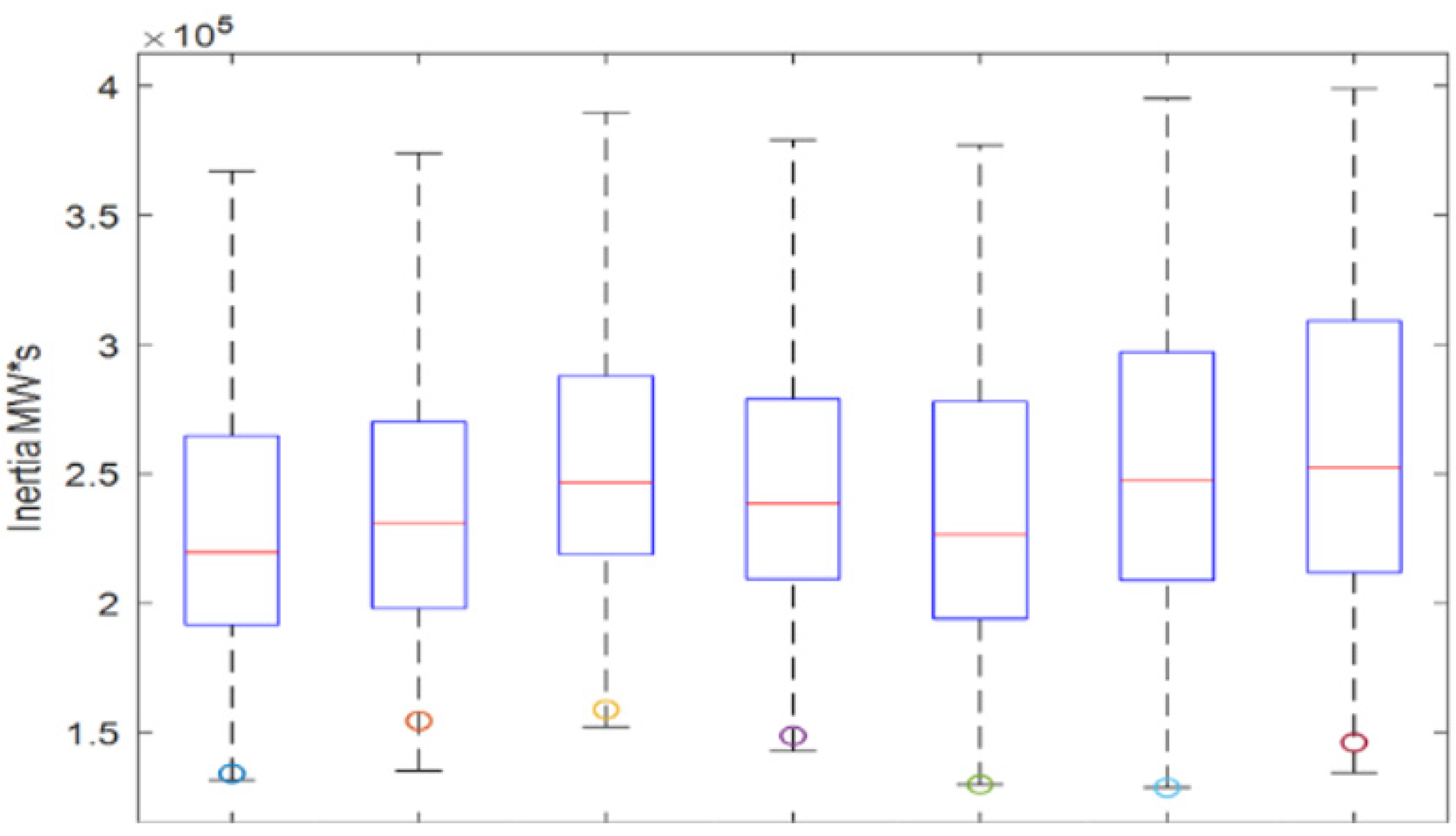
Figure 1. Inertia trends in ERCOT.
Energies 15 04937 g001
Figure 2. UK’s national inertia [9].
Energies 15 04937 g002
Figure 3. Implementation road map of the GFM controls.
Energies 15 04937 g003
Figure 4. Power system stability criteria.
Energies 15 04937 g004
Figure 5. Phase portrait of GFM control [50].
Energies 15 04937 g005
Figure 6. Virtual power angle curve [51].
Energies 15 04937 g006
Figure 7. Factors affecting system stability.
Energies 15 04937 g007
Figure 8. Timescale frequency dynamics.
Energies 15 04937 g008
Figure 9. Futuristic power system stability framework.
Energies 15 04937 g009
Figure 10. Synchronverter.
Energies 15 04937 g010
Figure 11. Synchronverter control architecture.
Energies 15 04937 g011
Figure 12. Control architecture of matching control GFM converter.
Energies 15 04937 g012
Figure 13. Dead zone oscillator.
Energies 15 04937 g013
Figure 14. Control architecture of dVOC.
Energies 15 04937 g014
Figure 15. V-f control architecture.
Energies 15 04937 g015
Figure 16. Single-mode V-f control.
Energies 15 04937 g016
Figure 17. Dual-mode V-f control.
Energies 15 04937 g017
Figure 18. Classification overview of inertia-emulating topologies.
Energies 15 04937 g018
Table 1. Data corresponding to Figure 1.
Time and Date2013
14 March 2013
3:00 a.m.
2014
30 March 2014
3:00 a.m.
2015
25 November 2015
2:00 a.m.
2016
10 April 2016
2:00 a.m.
2017
27 October 2017
4:00 a.m.
2018
3 November 2018
3:30 a.m.
Min Synch Inertia (GW’s)132135152143130128.8
System Load at Min. Synch Inertia (MW)24,72624,54027,19027,83128,42528,397
Non-Synch Gen. in % of system Load313442475453
Table 2. Major issues in power converter stability.
Priority RankIssues
1Inertia
2Transient stability
3Variety of load during frequency containment
4Power converters integration
5Lack of reactive power
6Power oscillations
7Voltage and frequency dip
Publisher’s Note: MDPI stays neutral with regard to jurisdictional claims in published maps and institutional affiliations.

