Article

Numerical Simulation of Premixed Methane–Air Explosion in a Closed Tube with U-Type Obstacles

1
National-Local Joint Engineering Laboratory of Harbor Oil & Gas Storage and Transportation Technology, Zhejiang Ocean University, Zhoushan 316022, China
2
School of Petrochemical Engineering & Environment, Zhejiang Ocean University, Zhoushan 316022, China
3
Zhejiang Provincial Key Laboratory of Petrochemical Pollution Control, Zhejiang Ocean University, Zhoushan 316022, China
4
Department of Oil, Army Logistical University, Chongqing 401331, China
*
Author to whom correspondence should be addressed.
Energies 2022, 15(13), 4909; https://doi.org/10.3390/en15134909
Submission received: 31 May 2022 / Revised: 22 June 2022 / Accepted: 3 July 2022 / Published: 5 July 2022
(This article belongs to the Topic Advances in Clean Energies)

Abstract

:
Given the spatial structures and functional requirements, there are a number of different types of obstacles in long and narrow confined spaces that will cause a premixed gas explosion to produce greater overpressure and influence the flame behavior for different obstacles. Because the volume fraction of unburned gas changes with the changing height of the U-type obstacles, we can further study the influence on the volume fraction of the unburned premixed gas for the characteristics of the overpressure and the flame behaviors in the closed tube with the obstacles. The results show that after the premixed gas is successfully ignited in the pipe, the overpressure in the pipe greatly increases as the unburned premixed gas burns between the adjacent plates. Moreover, the increase of the overpressure in the closed duct becomes faster when the decrease of unburned gas becomes faster. The high-pressure areas between the plates move inversely compared with the direction of flame propagation when the height of the U-type increases, whereas the high pressure in the front of the flame moves further when the flame propagation passes all obstacles. In addition, the reversed flow structure of the flame is a coupling result for the overpressure caused by the flame propagation and the vortex between the plates. From the perspective of production safety, this study is a significant basic subject about the characteristics of overpressure and flame behaviors in a closed tube with obstacles.

1. Introduction

In the field of petroleum and chemicals, premixed methane–air causes a number of explosion accidents. Premixed gas results in extremely destructive explosions. After the flow field is disturbed by the obstacles, it causes the flow field to change from deflagration to detonation [1,2,3,4] if the premixed methane–air explodes in the closed space with obstacles, and the destructive explosion might be aggravated again. Therefore, from the perspective of production safety, this study is of great significance for preventing premixed methane–air explosions in a closed space with obstacles disturbance.
These obstacles, with different geometries, positions [5,6], blocking probability [7,8] and numbers of obstacles [9], all have different effects on the combustion and explosion of premixed gas. The research on this problem was mostly carried out through experiments [10,11] or simulations [12,13]. Patel et al. [14] built a platform of closed pipe with three flat obstacles and found the pressure of premixed methane–air drastically increased. Meanwhile, Xu et al. [15] suggested there were four development stages for the pressure, and Wang et al. [16] also found in the premixed gasoline and air explosion experiments that the progress of the pressure not only included four stages but further showed that the progress had nothing to do with combusted materials. Further, Wen et al. [17] reached a similar conclusion about the pressure by changing the number and location of three plates based on Patel’s experiment, and the times of the maximal pressure value were nearly equal for different operating conditions. In addition, Shiryanpour et al. [18] verified Patel’s experiment by simulation and suggested that the block shape obstacles also caused high pressure in a simulation experiment. Gubba et al. [19] found that the flame propagation could be influenced by the number of obstacles and its blocking rate and low pressure areas could appear [12] around the next plates, whereas its blocking rate decreased during the experiment of combining the block shape with plates. In addition, Na’inna et al. [20] suggested that it can cause higher pressure for appropriate blocking rate and separation distance of obstacles. After experimentation, Li et al. [21] suggested these obstacles could have a great influence on the explosion overpressure and the flame propagation based on the different shapes of trapezoid, circle, square and rectangle. Sheng et al. [22] and Yu et al. [23] found that compared with other geometric barrier plates, triangular barrier plates produced the largest overpressure and had the strongest influence on flame turbulence, which should be related to the sphericity coefficient of obstacles [24]. Xiao et al. [25] proposed that obstacles with tips would promote the generation of flow instability and produce more intense flame propagation behavior. Meanwhile, Li et al. also suggested cylindrical obstacles [26] or continuous round hole plates [27] had a similar influence for increasing pressure. If the shapes of obstacles were more complex, Qin et al. [28] suggested these obstacles can make overpressure more intense; in particular, plate obstacles with re-entrant had a significant influence on the overpressure. Li et al. [29] suggested that the overpressure explosion might stimulate the flame propagation and accelerate the flame propagation again, but the vortex caused by the obstacles can make the flame propagation unsteady [4]. The explosion overpressure, however, can also cause the flame to oscillate [30]. Luo et al. [31] found by conducting a numerical simulation that that flame front tip instability was related to the length of the obstacle, and the longer the obstacle, the faster the explosive overpressure and flame propagation speed in the tube. Meanwhile, Qin et al. [32] also believed that Rayleigh–Taylor (R–T) instability always accompanied and affected flame propagation in the process of combustion and explosion, whereas Kelvin–Helmholtz (K–H) instability had a greater impact on the flame front surface. Baroclinic torque is formed by the interaction between density gradient and pressure gradient.
The flame might appear the reverse flow in the deflagration. Chen et al. [33] found that there was a structure of reverse flow induced by the blocking obstacles in the flow field of premixed methane–air combustion during the experiment. In addition, Wang et al. [8] also showed that the flow field of premixed hydrogen and air also appeared as a unique structure in the experiment. Meanwhile, Chen et al. [34] suggested that the plate gaps also could stimulate the reverse flow, which showed that the blocking obstacles were similar to the plate gaps. That is to say, under the disturbance of obstacles in the deflagration, the structure of the flow field and the characters of the overpressure were influenced by the obstacles after explosion.
Many studies mainly focused on the numbers and shapes of the obstacles but didn’t take the characteristics of the overpressure and the flame behaviors for the volume fraction of the unburned premixed methane–air in the closed duct into consideration. The unburned volume fraction might be a significant factor in causing their change around the pressure and the flame surface; during the pressure-increasing stage, the flame has not yet been released from the closed pipe. With the same blocking rate, U-type obstacles were different from plates in the spatial structure. The combustion total of the unburned premixed gas can be changed by changing the height of the U-type that could not make unburned premixed gas instantly combust; so U-type might influence the flow structure and the flame propagation characteristics during the explosion.
This paper aims to investigate whether the characteristics of the overpressure and the flame behaviors in a closed tube are related to the volume fraction of unburned premixed gas with U-type obstacles. We firstly verified the effectiveness of the numerical simulation by reviewing the literature [35] and then carried out numerical simulation to study the subject.

2. Materials and Methods

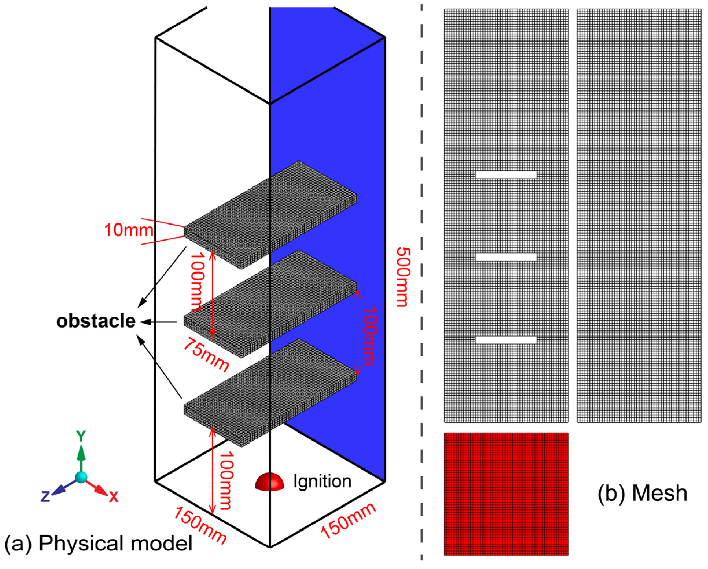
2.1. Physical Model and Mesh

In this paper, the experimental model of Wen et al. [35] was mainly used. As shown in Figure 1a, there were three obstacles with dimensions of 75 mm × 10 mm × 150 mm in a square pipe of 150 mm × 500 mm × 150 mm, and the distance between each obstacle was 100 mm. Before the explosion, stoichiometric premixed methane–air was contained in the pipe and the top and bottom of the pipe were closed, and the top was covered with a thin PVC membrane to prevent the leakage of premixed methane-air. An ignition device was set at the center of the bottom of the pipe, and a pressure sensor was set 40 mm next to the ignition source to monitor the change of pressure.
As Figure 1b shows, a mesh model was used in the simulation of the experiment. To meet the calculation requirements, as the Table 1 shows, the fluid area was divided into structured hexahedral grids with a uniform cell size by the ANSYS ICEM.

2.2. Combustion Model

The premixed combustible with the non-adiabatic model was used to calculate the combustion. To solve the problem that the initial flame thickness [36] was thin in the premixed combustible, the Zimont combustion model [37] made the flame front surface thicker. The equation of turbulent flame speed was as follows:
U t = A * ( μ Δ ) 4 / 3 S L 1 / 2 X 1 / 4 L Δ 1 / 4 ,
where, U t is the turbulent flame speed, A * is a model constant and is equal to 0.5, S L is the laminar flame speed, μ Δ is the sub-grid velocity, X is the unburnt thermal diffusivity and L Δ is the turbulence length scale.
The coupled equations of pressure and velocity were solved by the SIMPLE algorithm, where the under-relaxation factors ranged from 0.7 to 0.9.

2.3. Boundary Conditions and Initial Conditions

The vertical, bottom faces and obstacles of the closed pipe were set to adiabatic and non-slip wall because the ignited premixed methane–air was in contact with those surfaces for a very short time. In order to decrease the influence on the reflection of the pressure wave during the calculation, the top surface of the closed duct was set as the pressure outlet with non-reflection, without considering the influence of the thin PVC membrane for the pressure in pipe. The boundary condition can be seen in Table 2.

2.4. Numerical Details

Before calculation, the initial temperature and pressure were 300 K and 0 Pa, respectively. In addition, those parameters were set to zero for the velocity components, energy and reaction progress variables. A hemisphere with a radius of 5 mm [18,38] was patched in the center of the bottom of the tube as the ignition point, and the reaction progress variable of the patched part was set to 1 to simulate ignition.
Stoichiometric, premixed methane–air was considered as an ideal gas, where the specific heat was approximated by a piecewise polynomial fitting related to temperature; its viscosity was calculated using Sutherland’s law and the laminar flame velocity was regarded as a constant value, 0.36 m/s [7]. The heat of combustion was set to 55,643,750 J/kg, and the unburnt fuel mass fraction was set to 0.055. The details of the premixed gas are shown the Table 3.
In order to ensure the convergence of the calculation results, the time step size was set to 1 × 10⁻⁶, and 40 iterations were required in each time step. Except for the energy equation and the progress variable equation, whose convergence criteria were lower than 1 × 10⁻⁶ and 1 × 10⁻³, respectively, all other equations were lower than 2 × 10⁻⁵.

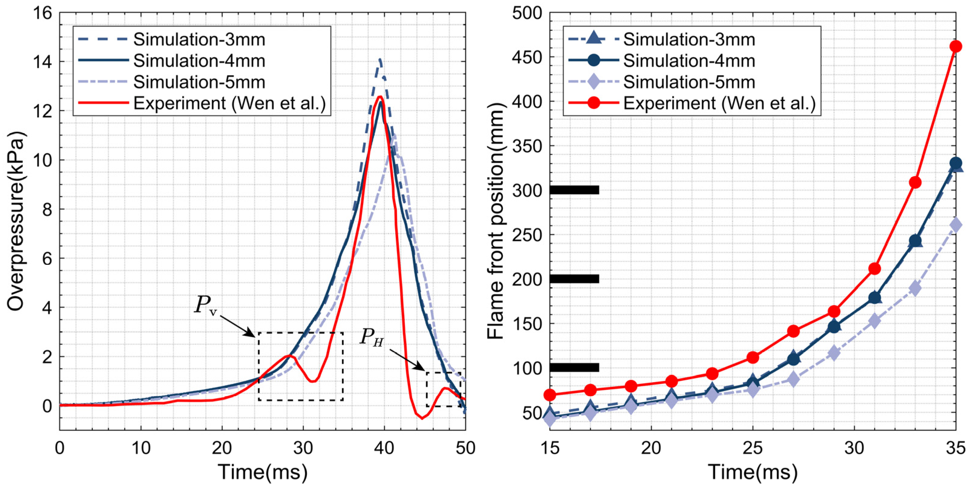
2.5. Numerical Verification

The experiment of (Wen et al.) aims to investigate the deflagration characteristics of the premixed methane–air in the closed tube with the obstacle plates in the different positions. The simulated results of the LES model in the paper are reliable according to the comparison with the experimental results of Wen et al. As Figure 2a shows, the premixed gas was successfully ignited in the experiment during the 5 ms period [35]. The flame propagated in the pipe formed the shape of a hemisphere [39] and fingertip before 25 ms had elapsed. At the 25 ms mark, the flame front surface connected with the first obstacle plate, and the flame shape became symmetrical horns on each side of the plates. The shape of flame propagation was a symmetrical antler in the closed duct until the flame rushed out of the pipe. Comparing the simulated progress of flame combustion with the experiment, as Figure 2b shows, the simulation results of the flame propagation progress might be similar to the experiment when the flame structure of the experiment is regarded as the comparison standard. In addition, the flame structure that was simulated also not did not contact the tube shell during the flame propagation.
According to the overpressure comparison curves from the Figure 3, the overpressure curves of LES were similar to the experiment with meshes of three different cell sizes before the peak value of the pressure. The decrease speed of the simulated pressure was slower than the experiment because the walls were set to be adiabatic and non-slip, so the high temperature could not shed heat from the closed tube after the peak value of the pressure [40]. There was a small pressure peak that might relate to the rupture process of the PVC membrane at the opening of the tube [4], such as the Pv in Figure 3. However, the simulated pressure did not appear as the small peak value because the PVC membrane wasn’t considered during the simulation process. From 40 ms to 48 ms, the burned and unburned premixed gas rushed out the tube with the rupture of the PVC membrane; there was negative pressure in the tube. The air outside the tube was drawn into the tube because of the pressure difference, so the unburned premixed gas inside the tube was burned again, which created a small pressure peak, such as the PH in Figure 3. With the disappearance of the premixed gas in the tube, the pressure of the content of the tube gradually drops to 0. The process of numerical simulation was simplified by covering the PVC membrane at the outlet; therefore, there was not such a small pressure peak and it slowly returned to zero [8].
The simulated results of the flame front position, as Figure 3 shows, were also lower than the results of the experiment, but the changing tendency of the pressure curves was similar to the experiment. However, only the cell size of 4 mm was more accurate than others. To save computer resources, the cell size of 4 mm might be considered for other cases.

3. Results and Discussion

As Figure 4 shows, the obstacles of the experiment from the reference [35] have been re-constructed as U-types with three different heights (20 mm, 35 mm and 50 mm, respectively) without changing their blocking rates.

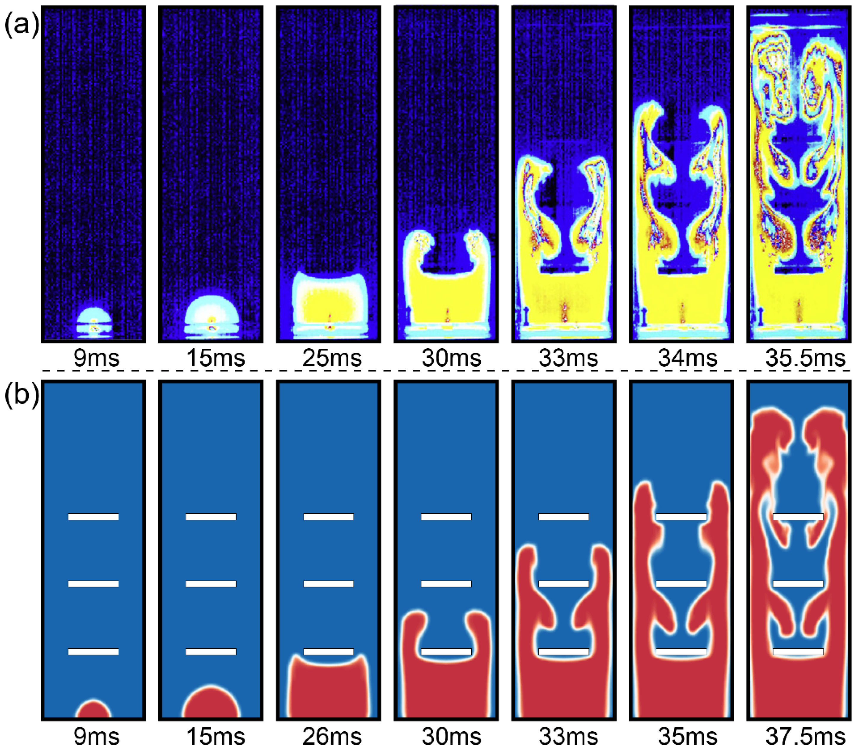
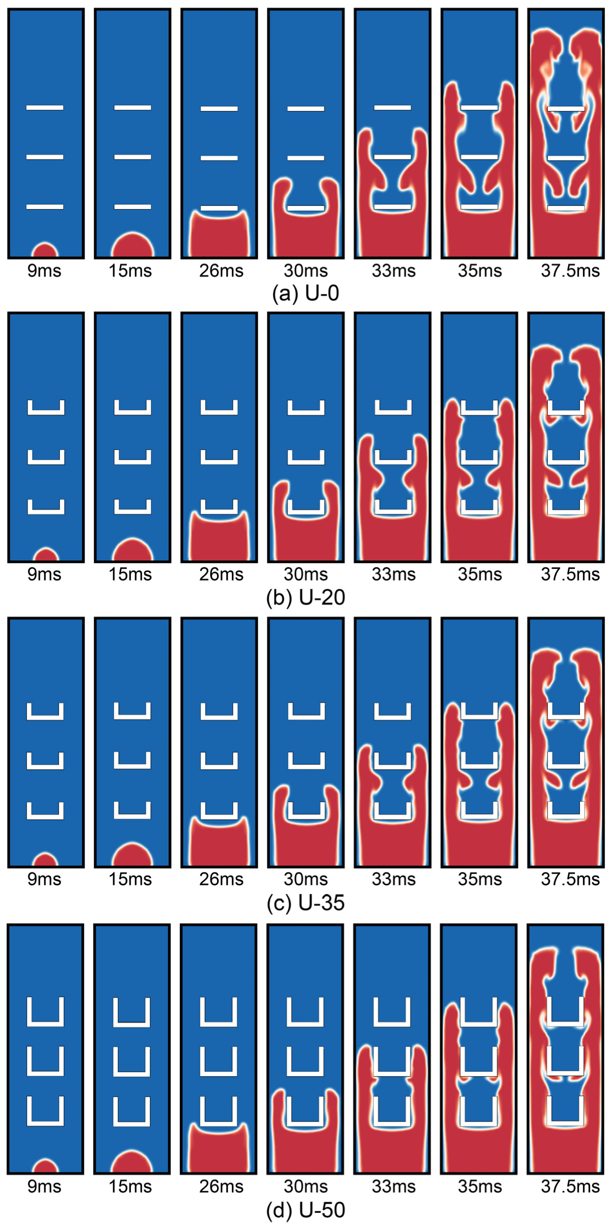
3.1. The Flame Structure

The flame structure of premixed gas during flame propagation is shown in Figure 5. The flame structure was gradually changed from the shape of a hemisphere to a fingertip to the symmetrical horns to the symmetrical antler in the closed duct with four U-type obstacles. At 26 ms, the front top of flame made contact with the surface of the first obstacle. At 30 ms, with the height of the U-type obstacles increasing, the flame propagation can not bend to the space between the adjacent plates and its propagation continued to extend along each side of the plates. This is because the flame propagation was obstructed by the U-type obstacles, which prevented the premixed methane–air between the plates from combusting. At 33 ms and 35 ms, the unburned premixed methane–air began gradually to burn when the flame propagation passed the second and third obstacles. The volume fraction of unburned premixed gas, however, slowly decreased between the adjacent plates because the flame propagation was obstructed by the increasing height of the U-type obstacles. At 37.5 ms, the spreading flame gradually advanced to the opening of the duct, but the volume fraction of burned premixed gas of the U-50 obstacle was less than that of the other U-type obstacles because of the restriction of those obstacles.

3.2. The Relation of the Flame Propagation, Velocity and Pressure

During the progress of flame propagation, the change of pressure and velocity in the field are shown in Figure 6. In order to study the coupling function of overpressure, velocity and flame front position, the fluid structure at 30 ms, 33 ms and 35.5 ms were regarded as research subjects. With high pressure in the field, the burned, premixed methane–air around the four obstacles formed vortexes behind the plates and created high pressure around the vortexes, as the annotated areas show, which related to the unburned premixed gas compassed in the flame front areas when the burned gas rapidly moved toward the opening of the duct.
Some unique structures of reverse flow were formed between the adjacent plates because of the influence on the vortex and high-pressure areas when the flame front position passed the obstacles, which was the result of the coupling function of the vortex and high pressure. However, these structures gradually decreased and even faded away with the increasing height of the U-type plates, as shown at 35 ms in Figure 5. When the height increased, the areas influenced by high pressure and the pressure values decreased with the decreased height at the same time because the influence of unburned premixed gas was gradually decreased, such as in the annotated areas at 30 ms and 33 ms. The flame of reverse flow continually burned those unburned premixed gases and caused those unburned gases to be compressed and combusted. Therefore, the created high-pressure areas could move toward the reverse direction of the flame propagation, as the annotated rectangles at 33 ms and 35 ms in the U-20 show. However, the phenomenon of moving high pressure didn’t appear in U-20, which related to the height of the U-type. This is because the flame in the U-0 plates bent to the space between two plates and the unburned premixed gases were also combusted by the flame front tip. Those spaces with high pressure can not create the pressure gradient, and the high-pressure areas cannot move toward the back. When the flame surface entirely passed all plates, the high-pressure field of the flame front position moved toward the opening of the closed tube with the increase of height of the U-type plates, such as in those annotated areas at 35.5 ms.

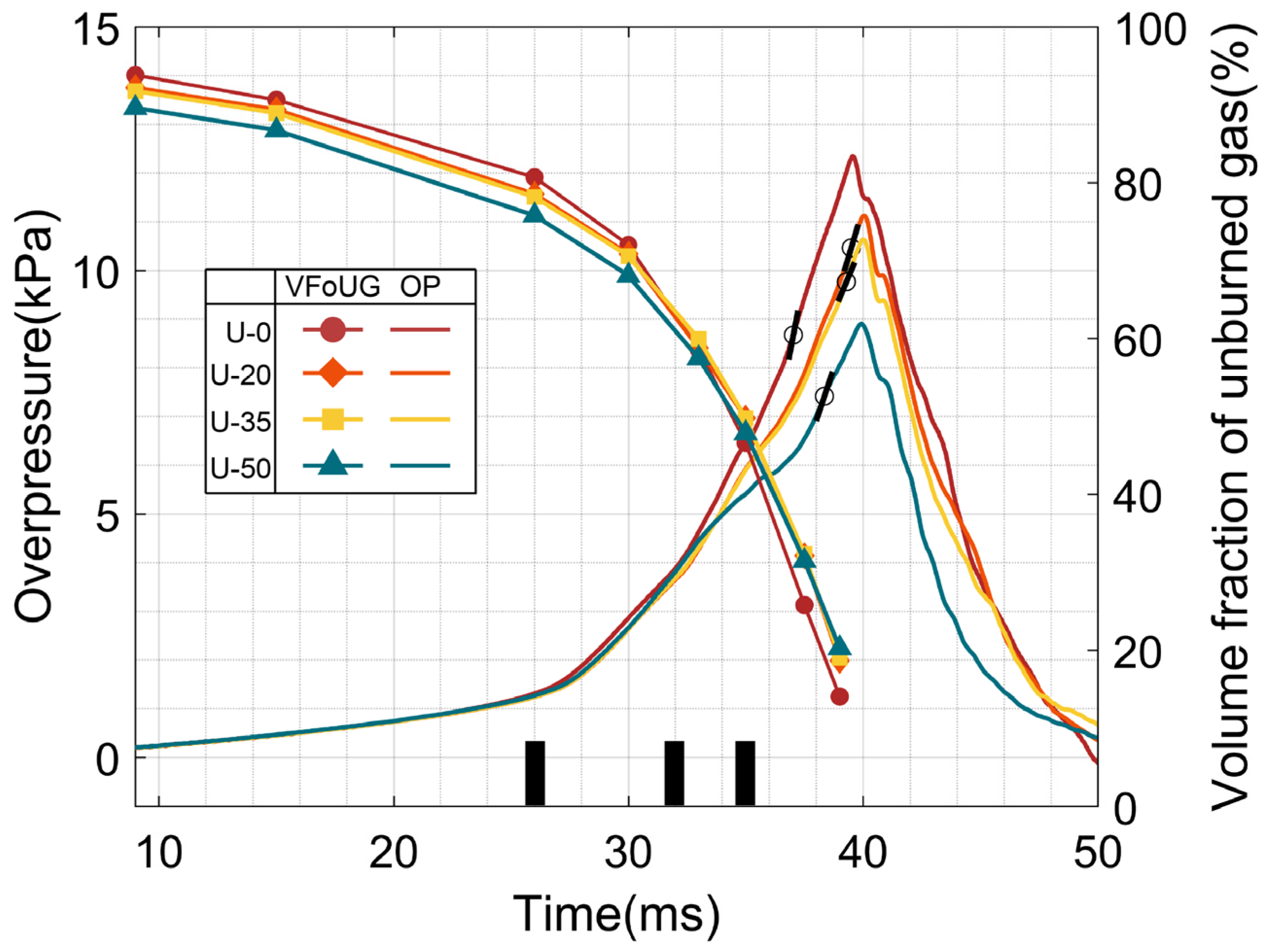
3.3. The Relation of the Unburned Premixed Gas and Pressure

Based on the analysis of the pressure, the velocity field and the flame shown in Figure 6, the overpressure is related to the volume fraction of unburned premixed methane–air in the closed tube. The change of overpressure and the volume fraction of unburned gas are shown in Figure 7. After ignition, the volume fraction of the unburned premixed gas rapidly decreased because the flame front position with different height continually went forward towards the opening of the duct, but the explosion overpressure, similarly, increased rapidly. The overpressure curves included four stages [16], and the peak value of pressure values appeared after the flame rushed out of the closed tube [41]. The time that the peak value of pressure appeared in U-20, U-35 and U-50 was later than that in U-0.
Before the flame front surface made contact with the obstacles, the volume fraction of unburned premixed gas gradually decreased, and the burned premixed gas also displayed relatively lower overpressure. It turned out that the pressure in the tube firstly can considerably increase because unburned gas was compressed and combusted and its volume fraction began to rapidly decrease when the flame front position was between the first and second plates, from 26 ms to 32 ms in Figure 7. With the flame propagating continually, the unburned premixed gas between the first and second plates burned further, and the gas began to burn when the flame passed the space between the second and third plates, which caused the overpressure in the closed duct to increase, from 32 ms to 35 ms in Figure 7. Until the flame entirely rushed out of the tube, the pressure in the closed tube increased for the last time and the volume fraction of unburned premixed gas still rapidly decreased after 35 ms, as shown in Figure 7.
The maximum overpressure growth rate (max(dp/dt)) appeared in this stage as the black marks in the overpressure curves. As for U-0, the amount of the volume fraction of unburned gas of U-0 decreased, mostly because the volume fraction might decrease slowly with the increasing height, which caused a huge increase in the overpressure of the U-type. Similarly, the overpressure of U-50 could be a small increase, as its volume of fraction decreased was minor.
After 35 ms, as Figure 5 shows, when the flame has entirely passed all types of obstacles, the unburned premixed gas of the flame front tip became less and less, but there was a surplus of unburned gas, which caused the unburned gas to be combusted by the burned flame of reverse flow, and the pressure in the tube continually increased. The overpressure gradually began to decrease and became atmosphere in the tube because unburned gas can not ensure continual combustion when the flame rushes out of the opening of tube.

4. Conclusions

For the U-type obstacle plates with a spatial structure that is different from that of the plates, the characteristics of the overpressure and flame behavior during the discharging process are closely related to the volume fraction of unburned premixed gas in the closed tube. Moreover, the importance of the analysis is that it can illuminate the special mechanism of combustion and explosion and thereby greatly decrease oil and gas deflagration accidents caused by obstacle disturbance. The potential significance of the research results is that it can greatly provide scientific guidance for the investigation of oil and gas deflagration accidents. According to the study, the following conclusions can be drawn:
(1)
In the process of combustion and explosion, the flame front surface that has been burned cannot access the gap between the adjacent plates in time after increasing the height of U-type obstacles, which causes the unburned premixed gas between the adjacent plates to not be burned in time. Furthermore, it also makes the burning premixed gas volume fraction in the whole tube decrease and eventually leads to an explosion overpressure value lower than that in the complete combustion.
(2)
The faster the volume fraction of unburned premixed gas decreases in the process of discharging explosion, the faster the explosion overpressure rises, and the maximum overpressure growth rate also appears in the period that the flame front tip completely breaks out of the tube.
(3)
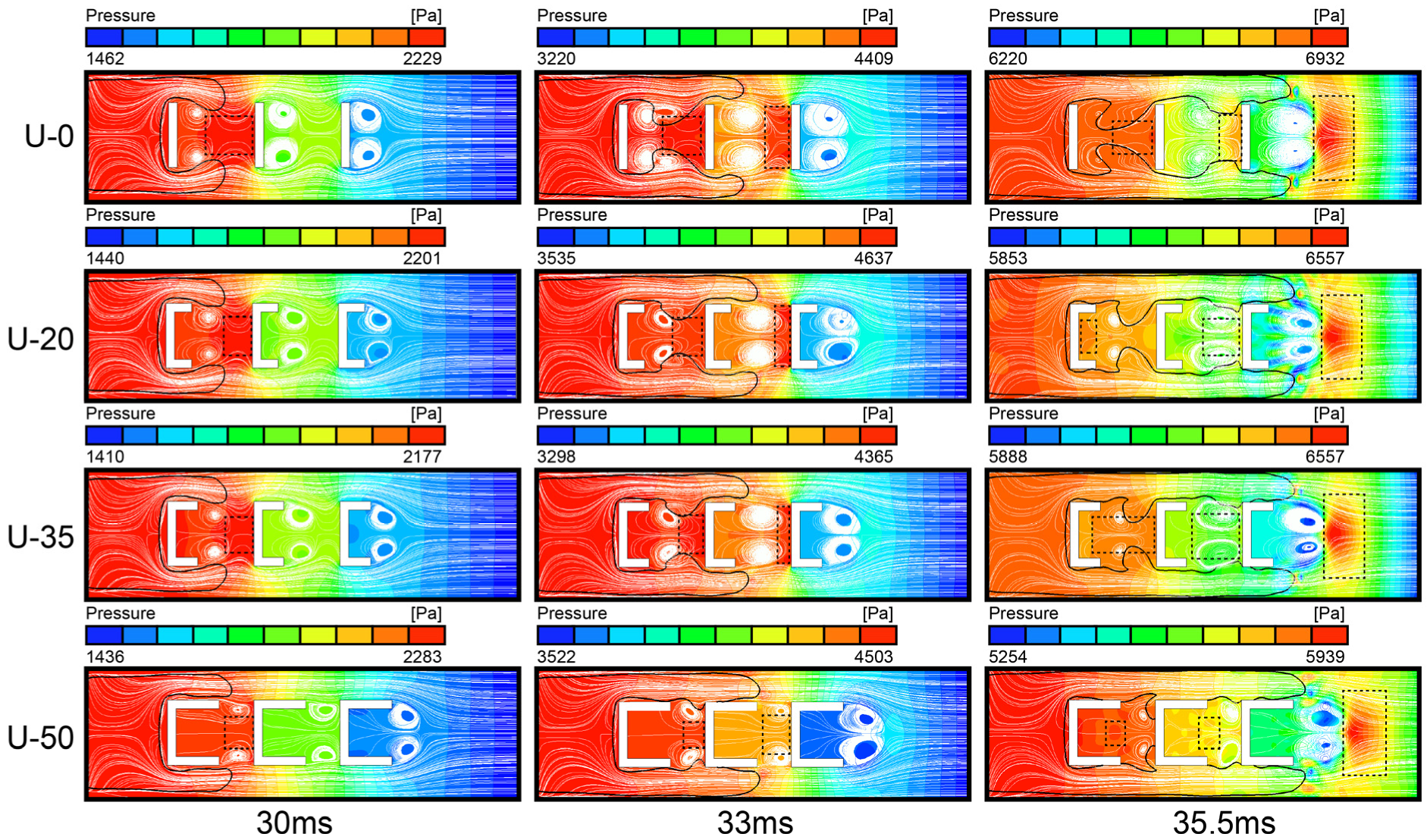
After increasing the height of the U-type obstacles, the moving direction of the high- pressure areas between the plates is opposite to that of the flame, whereas the high pressure areas in front of the flame moves in the same direction as the flame when the flame propagation passes all obstacles.
(4)
The reverse flow structure of flame between the plates is the result of the coupling between the high-pressure areas induced by the combustion of unburned premixed gas and the vortex structure.

Author Contributions

Conceptualization, B.H. (Bin Hao) and J.G.; methodology, B.H. (Bin Hao); software, X.J.; validation, B.H. (Bin Hao); formal analysis, B.H. (Bin Hao), B.G. and B.A.; writing—original draft preparation, B.H. (Bin Hao); writing—review and editing, B.H. (Bin Hao), B.G., B.A. and B.H. (Bingyuan Hong); supervision, J.G.; funding acquisition, J.G. All authors have read and agreed to the published version of the manuscript.

Funding

This research was funded by The Basic Public Welfare Research Project of Zhejiang Province, grant number LGF22E040002.

Institutional Review Board Statement

Not applicable.

Informed Consent Statement

Not applicable.

Data Availability Statement

Not applicable.

Conflicts of Interest

The authors declare no conflict of interest.

References

  1. Li, M.; Liu, D.; Shen, T.; Sun, J.; Xiao, H. Effects of obstacle layout and blockage ratio on flame acceleration and DDT in hydrogen-air mixture in a channel with an array of obstacles. Int. J. Hydrogen Energy 2022, 47, 5650–5662. [Google Scholar] [CrossRef]
  2. Gamezo, V.N.; Bachman, C.L.; Oran, E.S. Flame acceleration and DDT in large-scale obstructed channels filled with methane-air mixtures. Proc. Combust. Inst. 2021, 38, 3521–3528. [Google Scholar] [CrossRef]
  3. Xu, J.; Ni, Z.; Lu, B.; Xu, J. Experimental study on explosion of gasoline-air mixture and its suppression in pipeline with large length-diameter ratio. J. Saf. Sci. Technol. 2021, 2, 77–83. [Google Scholar]
  4. Wang, G.; Zhang, J.; Li, D.; Chen, X. Large eddy simulation of impacted obstacles’ effects on premixed flame’s characteristics. Explos. Shock Waves 2017, 1, 68–76. [Google Scholar]
  5. Li, G.; Wu, J.; Wang, S.; Bai, J.; Wu, D.; Qi, S. Effects of gas concentration and obstacle location on overpressure and flame propagation characteristics of hydrocarbon fuel-air explosion in a semi-confined pipe. Fuel 2021, 285, 119268. [Google Scholar] [CrossRef]
  6. Zheng, K.; Song, C.; Yang, X.; Wu, J.; Jiang, J.; Xing, Z. Effect of obstacle location on explosion dynamics of premixed H2/CO/air mixtures in a closed duct. Fuel 2022, 324, 124703. [Google Scholar] [CrossRef]
  7. Chen, P.; Li, Y.; Huang, F.; Guo, S.; Liu, X. Experimental and LES investigation of premixed methane/air flame propagating in a chamber for three obstacle BR configurations. J. Loss Prev. Process Ind. 2016, 41, 48–54. [Google Scholar] [CrossRef]
  8. Wang, Q.; Luo, X.; Li, Q.; Rui, S.; Wang, C.; Zhang, A. Explosion venting of hydrogen-air mixture in an obstructed rectangular tube. Fuel 2022, 310, 122473. [Google Scholar] [CrossRef]
  9. Du, Y.; Li, G.Q.; Wang, S.M.; Qi, S.; Li, Y.C.; Wang, B. Effects of obstacle number on characteristics of vented gasoline-air mixture explosions. CIESC J. 2017, 7, 2946–2955. [Google Scholar]
  10. Li, Z.; Chen, L.; Yan, H.; Fang, Q.; Zhang, Y.; Xiang, H.; Liu, Y.; Wang, S. Gas explosions of methane-air mixtures in a large-scale tube. Fuel 2021, 285, 119239. [Google Scholar] [CrossRef]
  11. Li, R.; Luo, Z.; Cheng, F.; Wang, T.; Lin, H.; Liu, H. A comparative investigation of premixed flame propagating of combustible gases-methane mixtures across an obstructed closed tube. Fuel 2021, 289, 119766. [Google Scholar] [CrossRef]
  12. Dai, Q.; Zhang, S.; Zhang, S.; Sun, H.; Huang, M. Large Eddy Simulation of Premixed CH4/Air Deflagration in a Duct with Obstacles at Different Heights. ACS Omega 2021, 6, 27140–27149. [Google Scholar] [CrossRef] [PubMed]
  13. Nguyen, T.; Strebinger, C.; Bogin Jr, G.; Brune, J. A 2D CFD model investigation of the impact of obstacles and turbulence model on methane flame propagation. Process Saf. Environ. Prot. 2021, 146, 95–107. [Google Scholar] [CrossRef]
  14. Patel, S.; Jarvis, S.; Ibrahim, S.; Hargrave, G. An experimental and numerical investigation of premixed flame deflagration in a semiconfined explosion chamber. Proc. Combust. Inst. 2002, 29, 1849–1854. [Google Scholar] [CrossRef]
  15. Xu, C.; Cong, L.; Yu, Z.; Song, Z.; Bi, M. Numerical simulation of premixed methane–air deflagration in a semi-confined obstructed chamber. J. Loss Prev. Process Ind. 2015, 34, 218–224. [Google Scholar] [CrossRef]
  16. Wang, S.; Wu, D.; Guo, H.; Li, X.; Pu, X.; Yan, Z.; Zhang, P. Effects of concentration, temperature, ignition energy and relative humidity on the overpressure transients of fuel-air explosion in a medium-scale fuel tank. Fuel 2020, 259, 116265. [Google Scholar] [CrossRef]
  17. Wen, X.; Yu, M.; Ji, W.; Yue, M.; Chen, J. Methane–air explosion characteristics with different obstacle configurations. Int. J. Min. Sci. Technol. 2015, 25, 213–218. [Google Scholar] [CrossRef]
  18. Shiryanpour, I.; Kasiri-Bidhendi, N. Hydrogen flame propagation inside an obstructed chamber. Int. J. Hydrogen Energy 2019, 44, 25031–25041. [Google Scholar] [CrossRef]
  19. Gubba, S.R.; Ibrahim, S.S.; Malalasekera, W.; Masri, A.R. LES modeling of premixed deflagrating flames in a small-scale vented explosion chamber with a series of solid obstructions. Combust. Sci. Technol. 2008, 180, 1936–1955. [Google Scholar] [CrossRef] [Green Version]
  20. Na’inna, A.M.; Somuano, G.B.; Phylaktou, H.N.; Andrews, G.E. Flame acceleration in tube explosions with up to three flat-bar obstacles with variable obstacle separation distance. J. Loss Prev. Process Ind. 2015, 38, 119–124. [Google Scholar] [CrossRef]
  21. Li, G.; Du, Y.; Bai, J.; Wu, J.; Li, M.; Wu, X.; Zhu, L. Effects of flat obstacle channel shapes on characteristics of gasoline-air explosion. CIESC J. 2020, 4, 1912–1921. [Google Scholar]
  22. Sheng, Z.; Yang, G.; Li, S.; Shen, Q.; Sun, H.; Jiang, Z.; Liao, J.; Wang, H. Modeling of turbulent deflagration behaviors of premixed hydrogen-air in closed space with obstacles. Process Saf. Environ. Prot. 2022, 161, 506–519. [Google Scholar] [CrossRef]
  23. Yu, M.; Zheng, K.; Chu, T. Gas explosion flame propagation over various hollow-square obstacles. J. Nat. Gas Sci. Eng. 2016, 30, 221–227. [Google Scholar] [CrossRef]
  24. Shiryanpour, I.; Kasiri, N. Effects of sphericity coefficient and fuel type on flame propagation inside an obstructed chamber. Eur. Phys. J. Plus 2019, 134, 240. [Google Scholar] [CrossRef]
  25. Xiao, G.; Wang, S.; Mi, H.; Khan, F. Analysis of obstacle shape on gas explosion characteristics. Process Saf. Environ. Prot. 2022, 161, 78–87. [Google Scholar] [CrossRef]
  26. Li, G.; Du, Y.; Qi, S.; Wang, S.; Zhang, P.; Wei, S.; Li, M. Effects of obstacle position and gas concentration on gasoline-air explosion venting. CIESC J. 2017, 5, 2327–2336. [Google Scholar]
  27. Li, G.; Du, Y.; Qi, S.; Wang, S.; Li, M.; Li, R. Large eddy simulation on the vented gasoline-air mixture explosions in a semi-confined pipe with continuous circular hollow obstacles. Explos. Shock Waves 2018, 6, 1286–1294. [Google Scholar]
  28. Qin, J.; Tan, Y.; Wang, Z.; Pan, P. Experiment Study on Obstacle Shape in Pipeline Affected to Gas Explosion. Coal Sci. Technol. 2012, 2, 60–62. [Google Scholar]
  29. Li, X.; Wang, T.; Chen, B.; Zhou, N. Detonation characteristics of hydrogen-air premixed gas in barrier-filled pipelines. Oil Gas Storage Transp. 2021, 1–8. [Google Scholar]
  30. Han, S.; Yu, M.; Yang, X.; Li, H.; Ma, Z. Flame propagation mode transition of premixed syngas-air mixtures in a closed duct. Fuel 2022, 318, 123649. [Google Scholar] [CrossRef]
  31. Luo, G.; Tu, J.-Q.; Qian, Y.-L.; Jin, K.-K.; Ye, T.-J.; Bai, Y.; Gao, S. Impacts of Rectangular Obstacle Lengths on Premixed Methane–Air Flame Propagation in a Closed Tube. Combust. Explos. Shock Waves 2022, 58, 10–21. [Google Scholar] [CrossRef]
  32. Qin, Y.; Chen, X. Study on the dynamic process of in-duct hydrogen-air explosion flame propagation under different blocking rates. Int. J. Hydrogen Energy 2022, 47, 18857–18876. [Google Scholar] [CrossRef]
  33. Chen, P.; Li, Y.; Huang, F.; Zhang, Y. LES approach to premixed methane/air flame propagation in the closed duct with a square-hole obstacle. Explos. Shock Waves 2017, 1, 21–26. [Google Scholar]
  34. Chen, P.; Luo, G.; Sun, Y.; Lv, Q. Impacts of plate slits on flame acceleration of premixed methane/air in a closed tube. J. Energy Inst. 2018, 91, 563–572. [Google Scholar] [CrossRef]
  35. Wen, X.; Yu, M.; Liu, Z.; Li, G.; Ji, W.; Xie, M. Effects of cross-wise obstacle position on methane–air deflagration characteristics. J. Loss Prev. Process Ind. 2013, 26, 1335–1340. [Google Scholar] [CrossRef]
  36. Xiao, H.; Shen, X.; Sun, J. Experimental study and three-dimensional simulation of premixed hydrogen/air flame propagation in a closed duct. Int. J. Hydrogen Energy 2012, 37, 11466–11473. [Google Scholar] [CrossRef]
  37. Zimont, V.; Battaglia, V. Joint RANS/LES approach to premixed flame modelling in the context of the TFC combustion model. Flow Turbul. Combust. 2006, 77, 305–331. [Google Scholar] [CrossRef]
  38. Charlette, F.; Meneveau, C.; Veynante, D. A power-law flame wrinkling model for LES of premixed turbulent combustion Part I: Non-dynamic formulation and initial tests. Combust. Flame 2002, 131, 159–180. [Google Scholar] [CrossRef]
  39. Ou, Y.; Li, R.; Yuan, G.; Li, G. Experimental and numerical simulation of gasoline-air mixture explosion characteristics in semi-confined space. CIESC J. 2017, 11, 4437–4444. [Google Scholar]
  40. Zhou, N.; Wang, W.; Zhang, G.; Wang, Z.; Zhao, H.; Yuan, X.; Huang, W. Research on Flow Field Characteristics of Propane Air Explosion in a Long Tube with Obstacles. Ind. Saf. Environ. Prot. 2018, 3, 1–4, 55. [Google Scholar]
  41. Wang, S.; Li, X.; Cai, Y.; Li, G.; Qi, S. Explosion venting dynamics of fuel vapor-air premixed gas based on small scale experiments. CIESC J. 2021, 9, 4961–4972. [Google Scholar]
Figure 1. Physical model and mesh model of the experiment.
Energies 15 04909 g001
Figure 2. The rection progress of combustion: (a) Wen et al. [35]; (b) this study.
Energies 15 04909 g002
Figure 3. The comparison of the overpressure and the frame front position between the simulation with three meshes and the experiment from the ref. [35].
Energies 15 04909 g003
Figure 4. The different height of U-type obstacles.
Energies 15 04909 g004
Figure 5. The flame propagation progress: (a) U-0; (b) U-20; (c) U-35; (d) U-50.
Energies 15 04909 g005
Figure 6. The coupling relation of pressure, velocity and flame propagation.
Energies 15 04909 g006
Figure 7. The relation of the volume fraction of unburned premixed gas and pressure.
Energies 15 04909 g007
Table 1. The details of grids.
ParameterValue
Cell size3 mm4 mm5 mm
The total of hexahedral grids415,950183,19891,740
The total of nodes439,824197,028100,564
Angle90°90°90°
Aspect ratio1.0~1.21.0~1.181.0~1.5
Quality111
Table 2. Boundary condition and influence.
BoundaryMomentumThermalSpeciesNote
outlet0.0 Pa300 K0Non-Reflection
WallNo Slip0 W/m2-Adiabatic
Table 3. Detailed computational conditions.
ParametersValueParametersValue
Heat of Combustion (J/kg)55,643,750Specific Heat (J/kg·K)Piecewise Polynomial
Laminar Flame Speed (m/s)0.36Viscosity (kg/m·s)Sutherland’ law
Unburnt Fuel Mass Fraction0.055Initial patch radius (mm)5
Publisher’s Note: MDPI stays neutral with regard to jurisdictional claims in published maps and institutional affiliations.

