1. Introduction
With the challenges of global climate anomalies and energy crises, vehicle electrification has an increasing trend as an exciting solution for reducing greenhouse gas emissions and fossil fuel-based energy consumption. Electric vehicles (EVs) can be more environmentally friendly than traditional internal combustion engine vehicles (ICEVs), and their electric motors have a higher energy conversion efficiency. Furthermore, technologies such as regenerative braking for EVs can reduce energy consumption by approximately 20 to 30 percent [
1]. Over the past decades, great quantities of research and development have focused on EVs, aiming to improve their overall performance while respecting their reliability, safety, cost, and efficiency requirements.
There are three main types of electric machines used in electric vehicles: induction machines (IM), permanent magnet synchronous machines (PMSM), and switched reluctance machines (SRM). PMSM in particular, with its high power and torque density, low noise, and increased control precision, is heavily used in EVs by some mainstream automotive manufacturers. Meanwhile, the emerging wound rotor synchronous machine (WRSM) is used today by some manufacturers due to its controllable excitation field and its rare-earth-free characteristics.
However, harsh operating conditions, mechanical wear, component aging, or poor manufacturing can lead to some undesirable faults in EV powertrains. These faults are initially often negligible, but the severity of these faults may gradually increase and cause other components to fail. A sudden catastrophic failure may even cause EV systems to cease operation, resulting in serious safety risks [
2]. Therefore, a real-time fault diagnosis adapted to various operating modes and that detects different potential faults is necessary to ensure the safety of the driver and the EV.
More recently, the International Organization for Standardization (ISO) developed the functional safety standard ISO26262 [
3] to ensure the safety of electrical and electronic systems in road vehicles. The fault diagnosis included in automotive functional safety requirements is designed to detect faulty components in the system, determine their severity, and provide a basis for eventually realizing an appropriate control logic. Furthermore, for some faults, the ideal control strategy can compensate for the closed-loop performance of EVs through system hardware or software redundancy, by re-tuning controller parameters, or control loop reconfiguration.
2. Faults in Electric Vehicle Powertrain
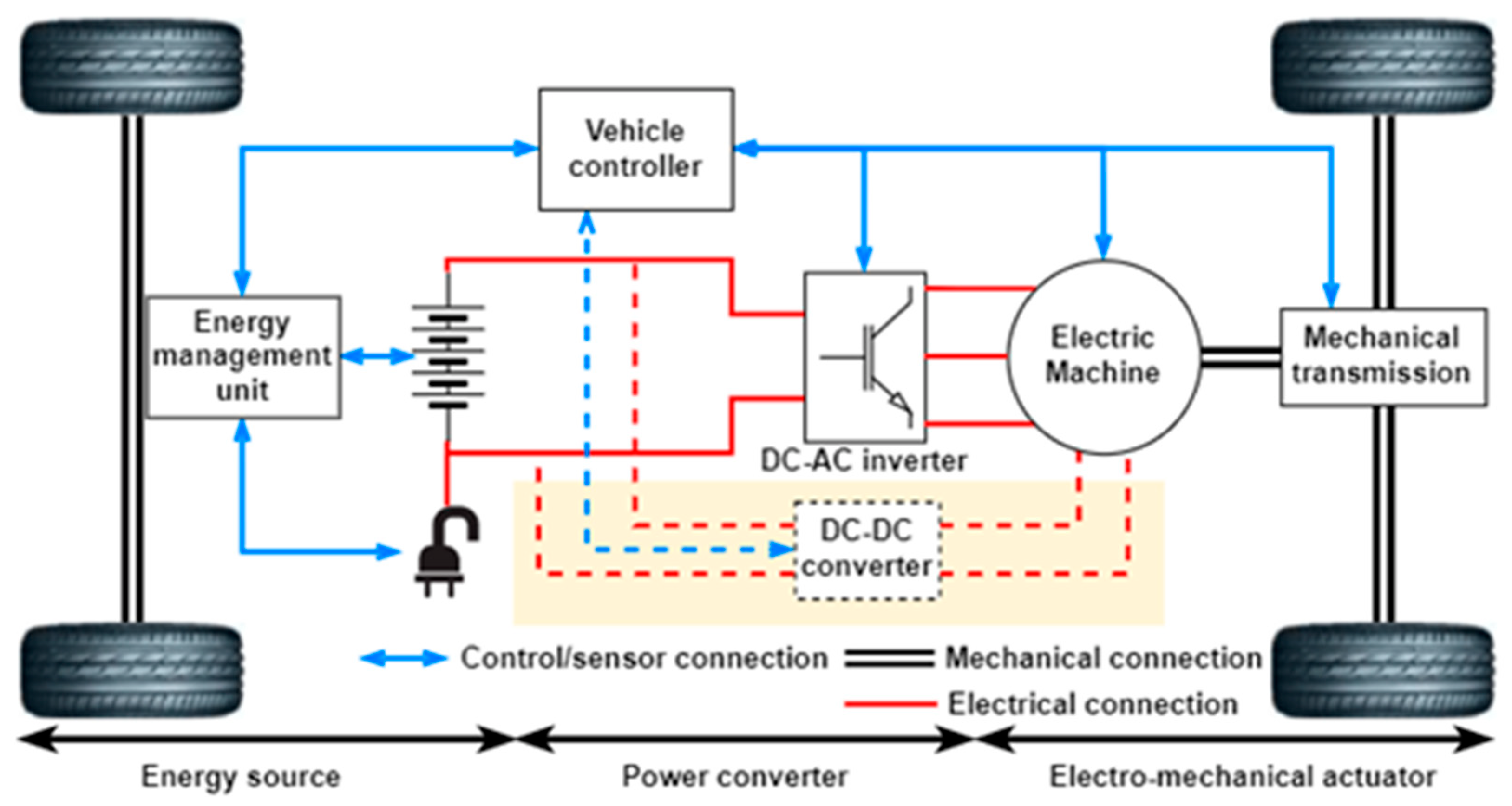
Figure 1 represents the architecture of a battery electric vehicle (BEV) powertrain, which primarily consists of a high voltage battery, vehicle controller, power converter, electric machine, and mechanical transmission. The highlighted parts indicate the external excitation supply required for some controllable rotor excitation machines. The battery and its Battery Management System (BMS) play a vital role. Nonetheless, due to their portability and applicability, various machines and their drive systems do not require specific proprietary battery modules, so this paper does not include battery faults.
The regular operating modes of the EV machine are normal operation and regenerative braking; the former converts the battery’s electrical energy into mechanical energy to drive the vehicle, while the latter transforms the engine’s mechanical power into electrical energy, which is stored in the battery. In other words, switching between engine mode and generator mode. However, the complex and compact architecture and various operating modes of modern electric vehicles (such as the traditional start–stop operation and regenerative braking) place particular demands on the electric machine and drive system used in the electric vehicle powertrain and increase the probability of faults occurring.
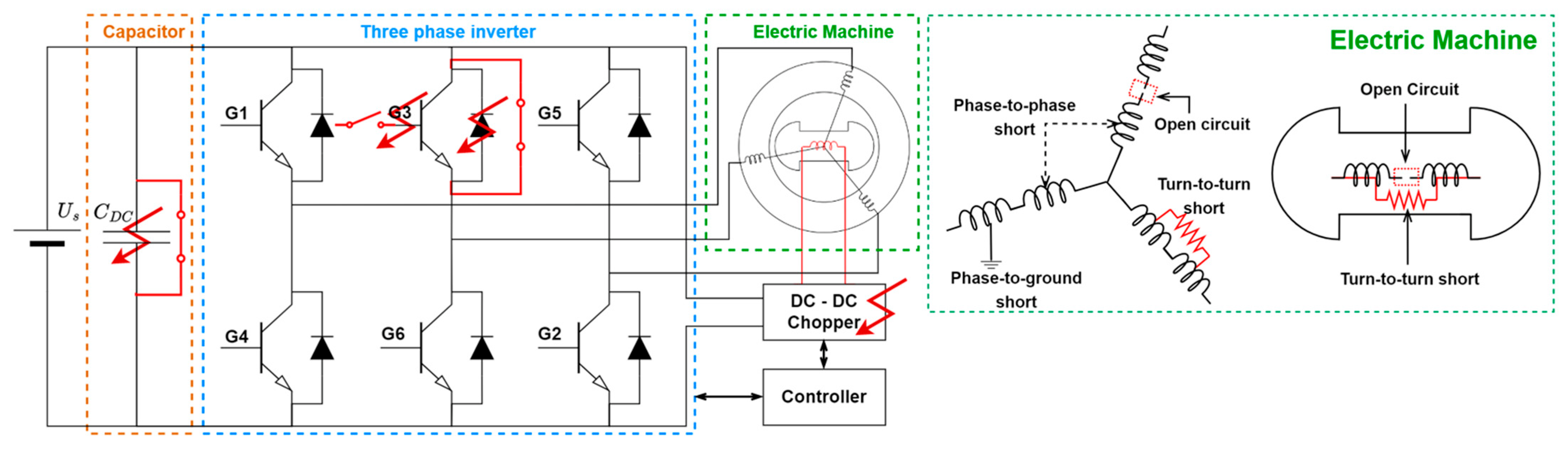
Figure 2 shows the components in the EV powertrain that are most likely to fail. These faults can mainly be divided into machine faults in the stator and the rotor, power converter [
4,
5,
6,
7], and sensor faults.
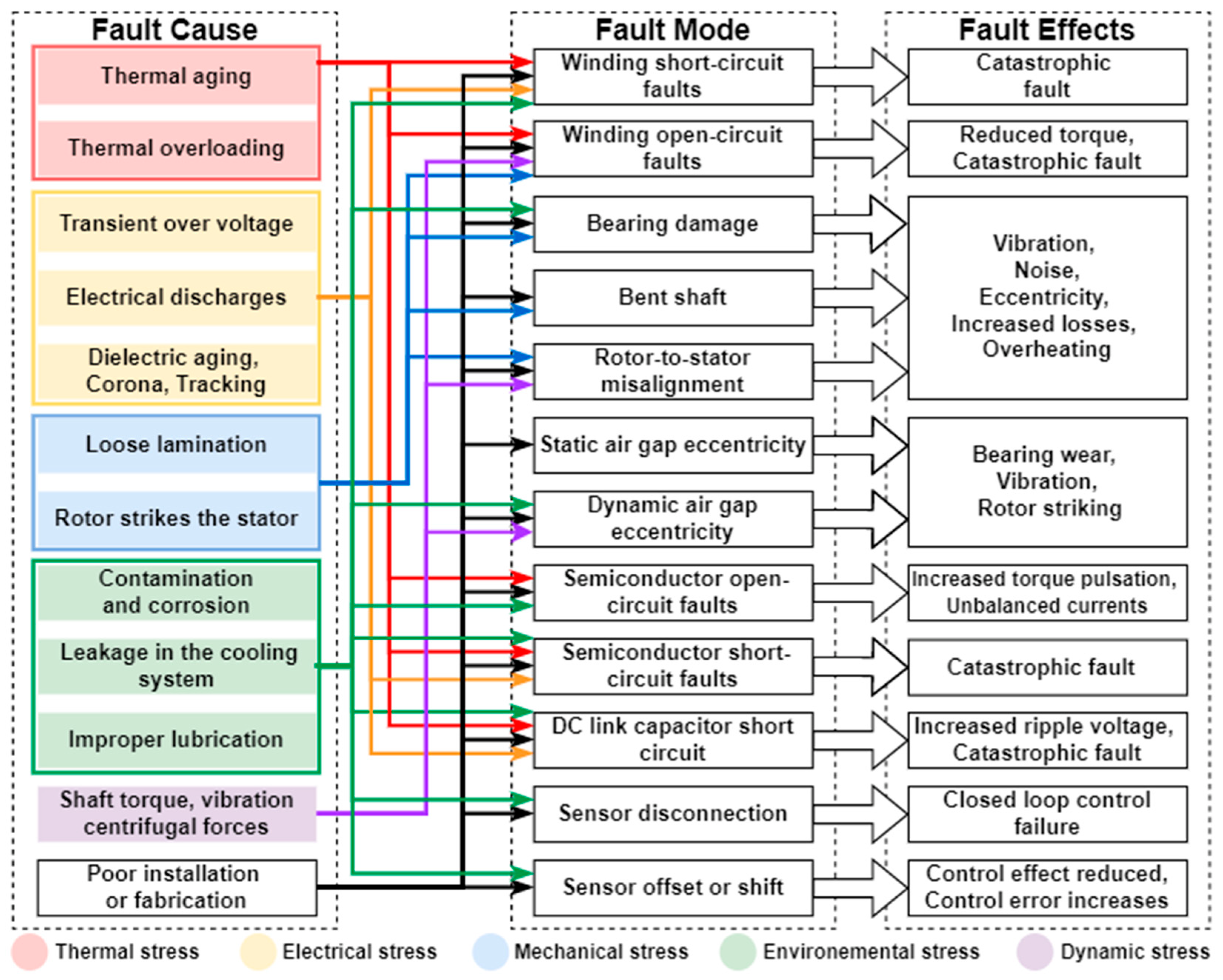
Root Cause Analysis (RCA) traces a fault mode back to its root cause that initially led to the series of failures [
8]. Based on this qualitative analysis method, a complex relationship between fault causes and effects can be constructed, which can be used to extract the characteristic features of specific faults for diagnosis. Based on this qualitative fault analysis method, a complex relationship between the causes and effects of faults in EV powertrains can be constructed [
3,
9], as shown in
Figure 3, which could be used to extract characteristic signals of specific faults for diagnosis. For instance, the red section under the fault causes is thermal stress, characterized by thermal overload and aging, which is the direct cause of a winding or semiconductor fault mode. In addition, these specific faults may lead to some undesired effects or negative performance characteristics.
3. Fault Diagnosis Methods for Electric Vehicle Powertrains
Fault diagnosis includes fault detection, fault isolation, and fault identification, and provides diagnostic results based on specific faults in the system to facilitate a fault assessment or implement fault-tolerant control [
10,
11]. For automotive applications, on-board diagnostics (OBD) regulations were introduced in vehicles in the late 1990s to enable real-time monitoring of the status of vehicle subsystems. However, the increasing complexity of electric vehicle powertrain architectures has made fault diagnosis techniques challenging.
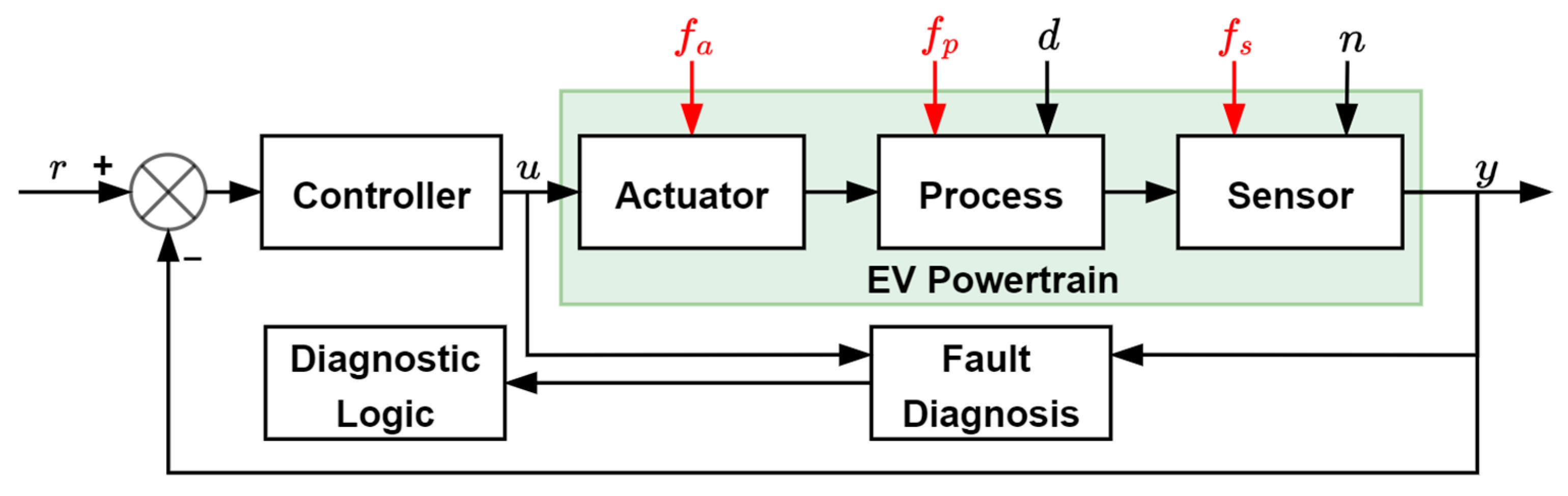
Figure 4 shows a block diagram of a typical EV powertrain fault diagnosis, a closed-loop system with r as the signal reference and y as the output, where each component is affected by the corresponding faults
, external disturbances
, and measurement noises
. In addition, generally, fault diagnosis methods are classified into model-based, signal-based, and knowledge-based methods [
12].
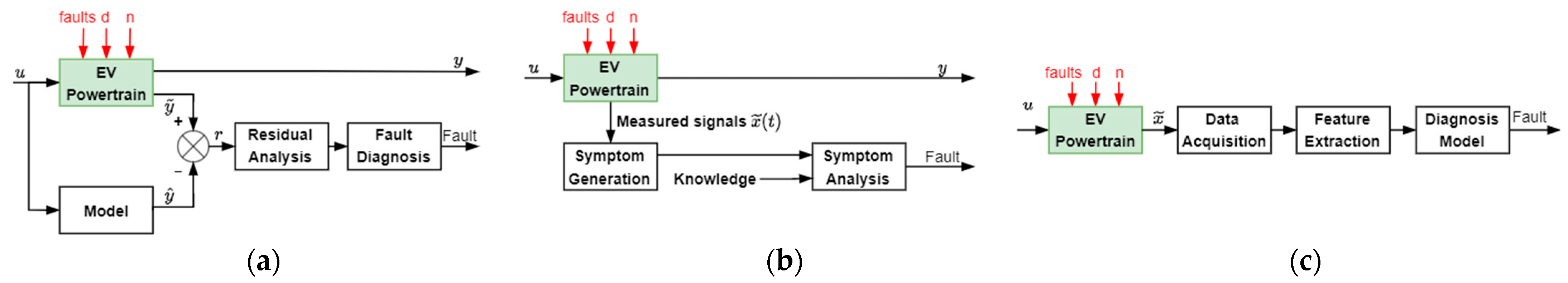
A model-based fault diagnosis has been proposed to replace hardware redundancy with the analytical redundancy described by mathematical equations, as shown in
Figure 5a. The results are compared and evaluated in terms of the residuals between the measured actual system output
and the predicted output
of the constructed model. However, this method is very dependent on the accuracy of the system modeling, and the uncertainty of the internal parameters and external disturbances can affect the diagnostic results. Signal-based methods use measured signals instead of system models for fault diagnosis, as shown in
Figure 5b. The system’s measured signal
is subjected to symptom analysis after feature extraction, which requires accurate knowledge as a criterion. According to the signal characteristics, such methods can be classified into time-domain signal-based and frequency-domain signal-based approaches. The method is no longer limited by the system model but relies on proper practical diagnostic knowledge and is generally not applicable to transient and non-stationary signals. Knowledge-based methods, as shown in
Figure 5c, such as neural networks or other artificial intelligence (AI) methods, are very accurate and do not depend on system parameters but require large amounts of training data and are costly.
Kolodziejek et al. [
13] proposed a hybrid frequency-domain signal-based and model-based method for a real-time diagnosis of the broken-bar faults of induction motor rotors, which can be used to realize the fault-tolerant control of variable-speed induction motor drives. This method uses recursive DFT (RDFT) and Goertzel DFT (GDFT) instead of traditional FFT algorithms to analyze the stator current signals and calculate fault-related harmonic components. The simulation results and the experimental results based on an induction motor with sensorless control show that the fault diagnosis algorithm has the advantages of accuracy and rapidity under the condition that the number of operations is significantly reduced, and it has low sensitivity to system parameter disturbance.
4. Fault-Tolerant Control Strategies for Electric Vehicle Powertrains
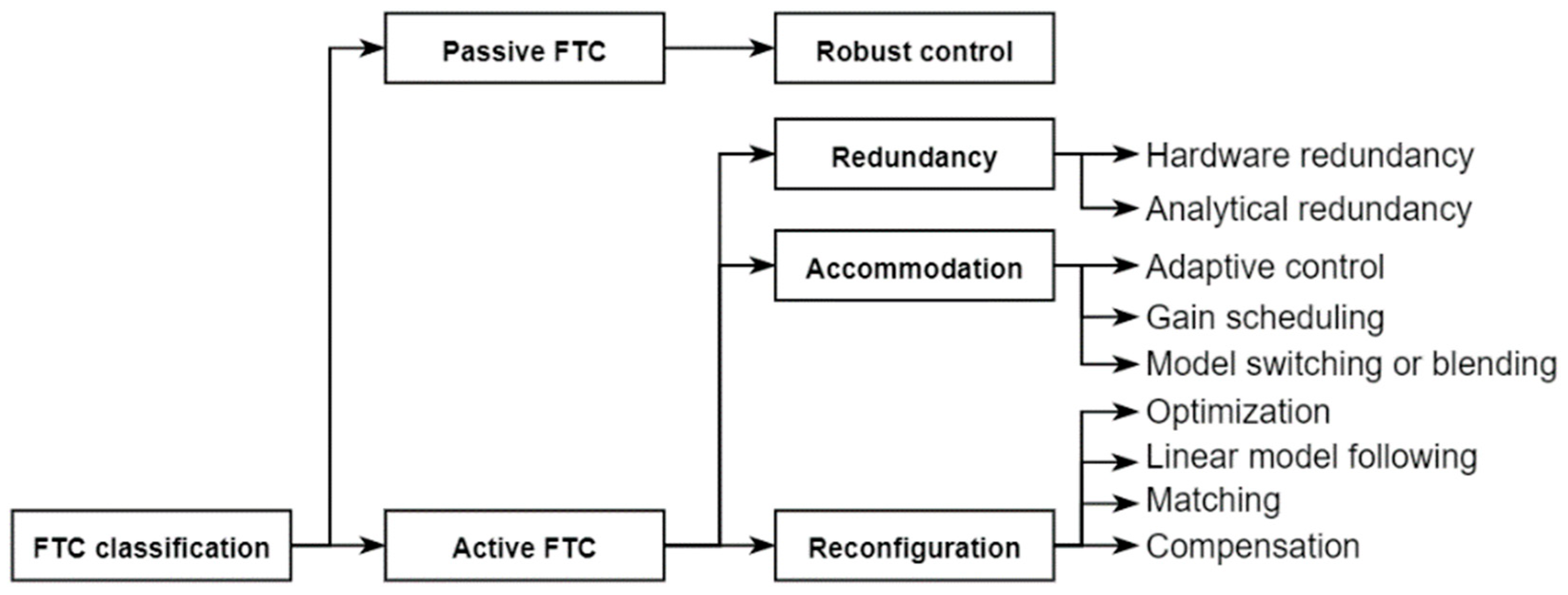
Fault-tolerant control is a control strategy that can keep the closed-loop system stable when sensors, actuators, or components fail and meet specific performance requirements, making the system’s feedback insensitive to faults. Fault-tolerant control (FTC) can generally be divided into passive and active methods. Passive methods are based on robust control. Passive approaches can be further subdivided into redundancy design, fault accommodation, and controller or system reconfiguration [
14].
Figure 6 shows the main categories of fault-tolerant controls.
Passive FTC does not rely on fault information in the system but considers the worst possible situation at the beginning of the design and reserves enough of a margin, using a robust compensator to reduce the impact of faults or stabilize the system. Some standard methods such as H-infinite control, sliding mode control, and Linear Quadratic control are used in some industrial fields. However, the robust control strategy of passive FTC relies on the assumption that the system remains an asymptotically stable closed-loop, which is insufficient for handling situations where the system experiences massive and unpredictable faults [
15].
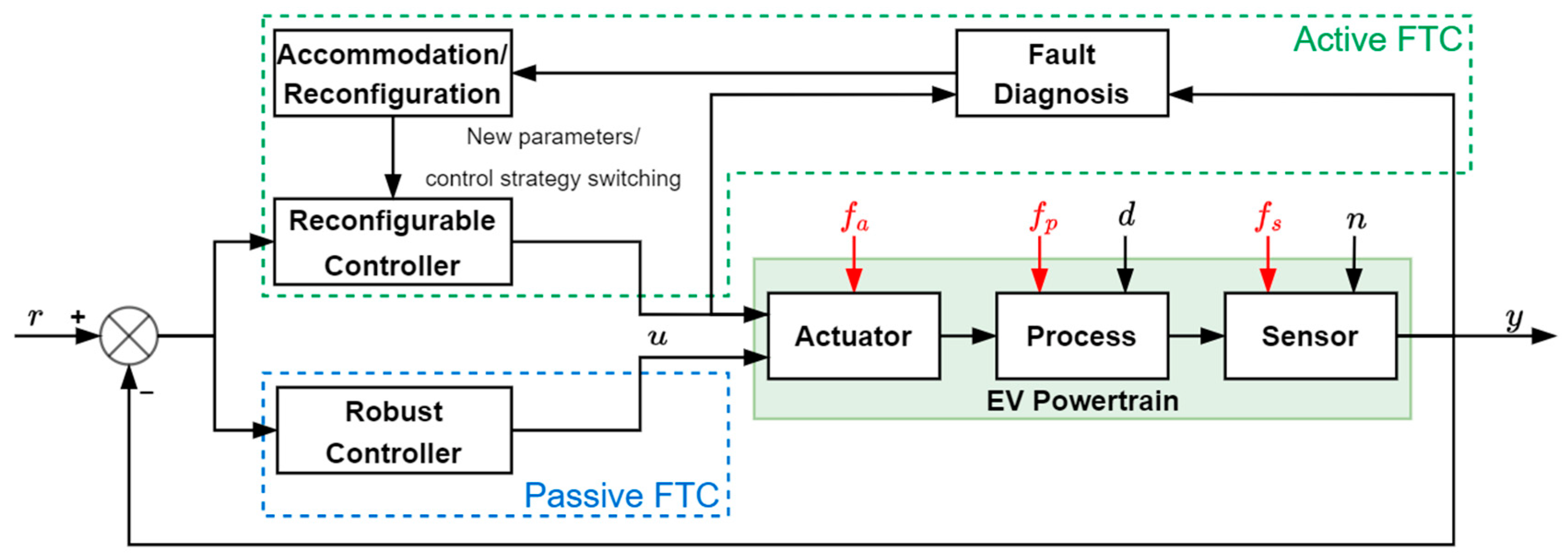
In contrast to passive FTC, active FTC may respond differently to various system faults, requiring detailed fault information in the system. That is to say, the fault diagnosis part plays a crucial role in active FTC, and inaccurate or wrong fault diagnosis results directly impact the control strategy’s performance and even lead to the system’s instability.
Figure 7 shows the general structure of active and passive FTC in the EV powertrain. Active FTC methods are divided into fault accommodation and controller or system reconfiguration. Fault accommodation generally refers to solely adjusting the parameters in the controller according to the fault identification information without changing the controller’s structure. Adaptive control is a typical example, where time, event, or system performance are variables, and the controller parameters can be tuned. Switching between pre-designed controllers could also be used as a fault accommodation strategy. The reconfiguration strategy usually changes the structure of the controller or control loop according to the fault. However, such methods still have disadvantages, such as the time spent on parameter retuning or control structure reconfiguration, and an excessive delay may lead to system instability [
14,
16].
Morel et al. [
17,
18] proposed a Filippov method-based control strategy with slope compensation, which is suitable for any interleaved or single-phase dc–dc converter to realize the fault-tolerant control of open-circuit faults. This method uses discontinuous functions to model the system, including regular operation and open-circuit faults. It obtains a set of Filippov solutions, proving the system’s stability and realizing switching between multiple states. The simulation results show that the method is suitable for a wide range of operating points of power loads, and it can be generalized to similar systems.
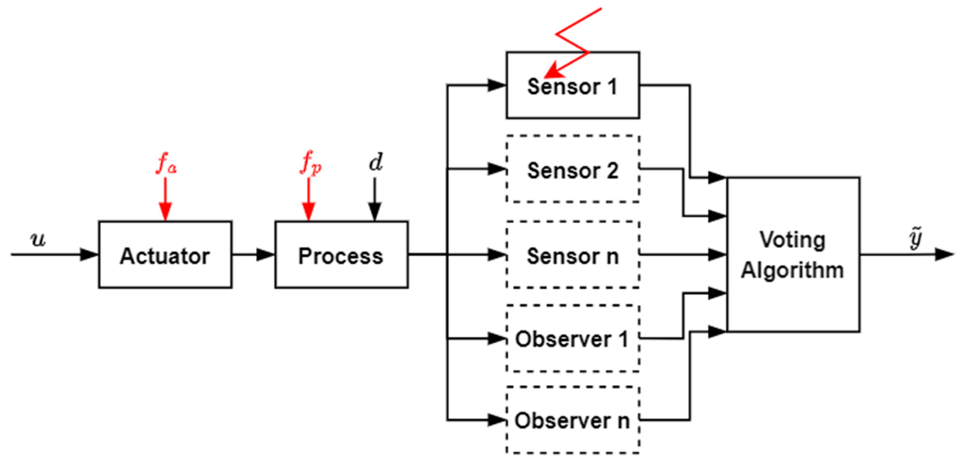
Redundancy is an effective strategy in the FTC system, which can be divided into two categories: hardware and software redundancy, and some research is based on hybrid redundancy. In the case of a hardware fault, the most direct and efficient solution is to use the same spare hardware for replacement [
19]. However, software redundancy is also a good choice, but is limited by some compact architectural space constraints or costs. Instead, using an analytical hardware model is more cost-effective, such as using one or more observers to estimate system parameters when a sensor fails. However, this FTC method requires a voting algorithm to decide the measurement to be used, either by directly selecting one or using some filtering algorithm to fuse them.
Figure 8 shows a scheme for hardware and software redundancy.
Alyoussef et al. [
20], Saadi et al. [
21], and Akrad et al. [
22] proposed the fault-tolerant control strategy based on virtual sensors for IM, SRM, and PMSM, respectively, using a sliding mode observer and extended Kalman observer as software redundancy for physical velocity sensors and applying artificial intelligence algorithms to diagnose sensor faults and optimize output signals. This method can select the appropriate observer according to different rotation speeds when the physical sensor fails. The simulation results show that the algorithm is suitable for the fault-tolerant control of the IM, SRM, and PMSM with speed sensor faults.
5. Conclusions
The papers published in this Special Issue proposed corresponding fault-tolerant control strategies for the faults of various components in EV powertrains. The experimental or simulation-related results have verified the reliability and accuracy of these methods. In addition, given the reliability and safety challenges of EVs, some future work scopes are aimed at the actual operating conditions of EVs, solving problems such as start-stop transients, high noise, and non-stationary signals in practice, and considering the trade-off between reliability and cost of fault-tolerant strategies. Furthermore, some AI techniques may become emerging methods for fault diagnosis and fault-tolerant control in highly coupled nonlinear automotive applications with different motor technologies.

