Abstract
In this paper, a detailed review of contemporary cooling systems of semiconductor devices is presented. The construction and the principles of operation of selected components of passive and active cooling systems, as well as selected computer tools supporting the design of such systems, are described. The dependences of thermal parameters calculated using these tools on selected factors characterizing the used cooling systems, e.g., the dimensions of their components, are presented and discussed. Additionally, some results of measurements illustrating the influence of selected parameters on the thermal resistance of power MOSFETs mounted in different cooling systems are shown. The properties of selected cooling systems are compared, and it is shown that by changing the type of cooling system, it is possible to reduce the thermal resistance value of a power MOSFET even 20 times. The presented considerations can make the process of designing cooling systems more effective.
1. Introduction
The cooling of electronic devices is an important problem in contemporary electronics [,,]. This problem becomes particularly important with an increase in the density of power generated in these devices. Traditional cooling methods employing metal heat sinks are insufficient in the case of high heat flux values [,]. Hence, a trend to search for new materials, as well as for new solutions improving the dissipation of heat generated inside electronic devices to the surroundings, is observed.
The problem of the effective cooling of electronic devices is a subject of the investigations of packaging constructors [,], as well as designers and constructors of electronic circuits containing these devices [,,]. This paper [] proves that the size of voids in the soldering joint practically has no influence on the efficiency of heat removal from a power semiconductor device. In turn, the paper [] presents the results of the measurements, which show that an increase in the dissipated power and the air flow speed led to an improvement in the efficiency of cooling of such devices. Special components of cooling systems, such as ultra-thin micro heat pipes and vapor chambers, are described and analyzed in detail in the papers [,].
The influence of selected factors on the efficiency of dissipation of the heat generated in electronic devices is discussed in many papers [,,,]. For example, in [] it is proved that for small power semiconductor devices, the length of terminals, the area of soldering points and the orientation in space visibly influence the efficiency of heat removal. The subject of such papers is often an analysis of the influence of a single factor on the efficiency of cooling [,,]. Many papers refer to different methods of modelling and the analysis of thermal properties of semiconductor devices [,,,,,].
Research efforts are focused both on the selection of new materials, which could be applied in cooling systems, and on the devices based on physical phenomena that were omitted earlier during the process and aimed at improving the cooling of the discussed class of devices. The interesting materials that are used to cool electronic devices are, among others, graphene, pyrolytic graphite synthetic and diamond, as well as ceramic and metal composites [,,]. In turn, among the modern solutions are heat pipes, vapor chambers, liquid chambers, high thermal conduction plates, single- and two-phase liquid cooling systems, systems utilizing latent heat of melting, and thermoelectric modules. Additionally, in the case of metal heat sinks, there have appeared many interesting innovative solutions and production methods allowing improved heat dissipation. The important part is that there are thermal interface materials used between the package of an electronic device being cooled and its cooling system. Additionally, in this field the contemporary science has made important advances, offering materials with improved properties. The information about new cooling systems can be found both in scientific papers [,,,,,] and in the materials shared by companies producing such systems [,,,,].
The development of cooling systems is accompanied by a need to elaborate their modeling and designing. Contemporary cooling systems are often designed using the FEM (Finite Element Method) and CFD (Computational Fluid Dynamics) methods [,,,]. The application of these methods requires, however, qualified and experienced personnel, as well as costly licenses and computers with the appropriate calculation power [,,,,,]. An alternative is designing tools shared by producers of cooling systems on their websites which support the design of such systems [,,].
The paper [] presents the results of electro-thermal simulations of multicellular SiC power MOSFETs using the SPICE-like simulation program. The manner of automatic generation of a compact thermal model from the accurate 3D mesh is described. The device is discretized into a chosen number of elementary cells (heat sources) and turned into a purely electrical macrocircuit. The investigations performed for a multicellular 4H-SiC VDMOS soldered on a DBC package show that potentially dangerous temperature gradients can be observed in the considered device.
The paper [] concerns the problem of a temperature sensor inserted into the neighborhood of a chip to monitor the junction temperature. The presented investigation results prove that it is possible to increase the power dissipation in certain periods of time without the temperature rising over the assumed limit and to increase the microprocessor’s throughput by 7%. The proper monitoring of the device junction temperature requires placing the temperature-sensing device inside the heat source.
The paper [] proposes a manner of computing the internal temperature of power LEDs situated in the modules containing multiple power LEDs, taking into account both self-heating in each power LED and mutual thermal couplings between each diode. The influence of the thermal pad surface area on the device temperature is investigated. It is shown that the use of a thermal pad can reduce the value of thermal resistance even by 10%.
The paper [] presents an analysis of the efficiency of selected algorithms used to solve heat transfer problems at the nanoscale. The case study is a MEMS structure. It is shown that the shortest thermal time constant for the tested structure can be very small; a number of picoseconds.
The paper [] describes an analysis related to thermal simulation of the test structure dedicated to heat-diffusion investigations at the nanoscale. The results of computations and measurements are presented and discussed. These results show that in the actual MEMS, very low values of thermal time constants characterizing self-heating and mutual thermal couplings in such a structure do not exceed several picoseconds.
The paper [] proposes a post-processing procedure for the network identification from thermal transient measurements. This so-called optimization-based network identification provides a much more accurate and robust result compared with the other approaches using the classical deconvolution algorithms. In the cited paper, it is shown that thermal time constants depend on the dimensions of the tested structure and can change from a few microseconds to a few seconds.
In this paper, a review and classification of classical and modern cooling systems of semiconductor devices and integrated circuits are presented and discussed. The construction and the principles of operation of these systems are described. In particular, the concept of the operation of these components constitutes its focus area. The following components of cooling systems are described: passive heat sinks, axial fans and blowers, heat pipes, high conduction metal plates, vapor chambers, thermosiphons, encapsulated conductive plates, single-phase and two-phase liquid cooling systems, immersion cooling systems, PCM heat sinks, thermoelectric modules and interface materials. Online tools supporting the design of cooling systems are also presented. Using the calculations results obtained with the use of these tools, an influence of selected factors on the efficiency of the analyzed cooling systems is illustrated. The results of the measurements carried out by the authors illustrating the influence of the cooling system selection and its operating conditions on thermal parameters of the cooled electronic device are also presented and discussed.
2. Classification of Cooling Systems
In this paper, a cooling system is understood to be all the components located between a package of the device being cooled and the surroundings. In the case of each cooling system, the atmospheric air is directed to the surroundings into which the heat is dissipated.
In engineering practice, the purpose of a cooling system is to maintain the temperature of the inside of a device, cooling below the specified maximum temperature. In a particular case, this temperature limit is the maximum inside temperature of the device Tjmax. An increase of the junction temperature above Tjmax causes a significant shortening of the device reliability and may also cause damage [,]. For this reason, the used cooling system needs to be selected in a way which ensures that the temperature of the device being cooled will not exceed the maximum temperature at the power and ambient temperature changes predicted in the design phase.
Cooling systems can be classified using various criteria. The commonly known classification is the division into passive and active systems. The passive systems do not require a supplying of external energy to work properly. In turn, active systems need the external energy to supply fans, pumps or thermoelectric modules, being parts of these cooling systems.
Some active cooling systems can work in a passive mode; however, their ability to dissipate heat in this mode is significantly lowered []. The passive operation of a cooling system is desired in the case when a high level of reliability is needed, e.g., in automotive applications. Passive cooling systems do not contain any moving parts, so they are generally maintenance free. In active systems, a typical value of the fans mean time to failure (MTTF) is more than 100,000 h. Regarding systems containing pumps, the value of the MTTF may be reduced even by half compared to the fans. The cooling systems equipped with moving parts—fans and especially pumps, due to wear of these parts over time—are less reliable than passive systems.
The frequently used classification of cooling systems is also the division into air cooled and liquid cooled systems.
This classification is very imprecise. In atmospheric conditions, the air is always the ultimate media that the heat is dissipated into. In the case of so-called liquid cooling systems, the heat is conducted from a cooled device to a cooling liquid and carried away to a remote heat exchanger, where it is dissipated into the atmospheric air. The heat transport to a remote heat exchanger can be achieved, e.g., by forcing the cooling liquid flow.
Taking a change of phase as the classification criterion, cooling systems may be divided into single- and two-phase systems []. This classification refers to liquid based cooling systems, as well as the systems using phase change materials (PCMs). In two-phase systems, a change of phase of a cooling liquid takes place from liquid to vapor during heat absorption and from vapor to liquid during heat rejection. In the PCM systems, the phase of the PCM material turns from solid into liquid during heat absorption and from liquid into solid during heat rejection.
A separate group of cooling systems are the ones making use of thermoelectric modules [,,]. Thermoelectric modules are electronic devices able to absorb thermal energy on one side of the module and transfer this energy to the other side. Properly designed cooling systems using thermoelectric modules allow for bringing the temperature of the cooled device down below the ambient temperature, which is not possible using the other cooling systems mentioned in this section.
3. Review of the Components of Cooling Systems
Except for the simplest passive solutions, cooling systems are typically made of at least two components. In this section the construction and principles of operation of the components used in cooling systems are described.
3.1. Passive Heat Sinks
Passive heat sinks are the most basic solution used in cooling systems. Cooling with heat sinks takes place in a way of heat conduction and spreading in the heat sink material. Next, the heat is dissipated from the surface of the heat sink in the atmospheric air in the way of conduction, convection and radiation. Convection may be naturally driven by buoyancy forces or forced, e.g., by a fan.
Heat sinks are typically made of metals having high thermal conductivity λ—aluminum (λ ≈ 200 W/(m∙K)) and copper (λ ≈ 400 W/(m∙K)), and sometimes also as constructions combining these two metals, e.g., in the form of a copper core and the external part made of aluminum []. The use of a metal core of twice higher thermal conductivity allows for improving the overall performance of such heat sinks. Due to a density about three times larger and double the price of copper, the most frequently used heat sinks are made of aluminum. Depending on the required parameters (dimensions, geometry and price), metal heat sinks are made in various technologies, such as extruding, forging, skiving, stamping, die casting, fin bonding and machining.
Thermal properties of metal heat sinks depend on the technology and the material used. For example, the thermal conductivity of aluminum alloy A380.0 used for die casting is λ = 109 W/(m∙K), whilst in the case of so-called pure industrial aluminum 1070, used in cold forging, it is λ > 235 W/(m∙K) [].
In the case of aluminum, heat sinks dedicated to work inside the devices enclosures in natural convection conditions the surface anodization are used in order to increase their thermal emissivity and the amount of thermal energy radiating from the surface of such heat sinks. The thermal resistance of heat sinks made of raw aluminum in natural convection conditions is about 10–15% larger compared with the same heat sink with a black anodized surface []. The thermal resistance of metal heat sinks in such conditions may also vary by about 15–20% depending on their orientation.
In Figure 1, the examples of metal aluminum heat sinks made of raw and black anodized aluminum are shown.
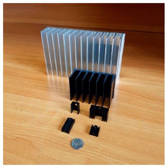
Figure 1.
Examples of a passive heat sink.
Other materials applied in heat sinks production are Al2O3, AlN, SiO2 and SiC. These materials are noncorrosive, do not oxidize, are water resistant, have lower mass per volume unit and do not conduct current [,]. Composite materials are often used as thermoconducting substrates; however, they are not as widespread as individual elements. This application of composite heatsinks is limited to low power. The main drawbacks of these materials are typically lower thermal conductivity compared with metals, higher costs of production and technological limitations in the manufacture of the desired shapes.
For cooling small power devices, the heat sinks made of polymer materials are offered []. It is worth noting that thermal conductivity of the materials used in heat sink production depends on temperature. In the temperature range of 0 °C to 150 °C, typical for many semiconductor devices, this dependence may be both a decreasing as well as increasing function of temperature [].
3.2. Axial Fans and Blowers
Axial fans and blowers are a commonly used solution in order to increase cooling efficiency when passive operation is not a key requirement []. The role of an axial fan is to create airflow parallel to the axis of rotation of the fan blades. Axial fans pull the air on one side of the fan and force it out on the other side. Examples of the axial fans of various diameters compared to one dime coin (17 mm in diameter) are shown in Figure 2.
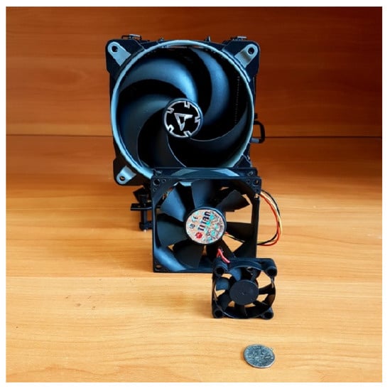
Figure 2.
Examples of axial fans of various diameters.
Axial fans are available in various function types, sizes, supply voltages and rotational speed ranges. Fan trays are used in high power applications, making it possible to obtain high-performance cooling at acceptable costs.
Blowers have a unique appearance. They are constructed of a plastic or metal cage within which a circular impeller spins. Blowers pull the air from the sides and send it out in the direction perpendicular in relation to the axis of the rotation of the impeller.
Blowers are produced in different sizes. They have many applications, e.g., in consumer electronics for hot spot cooling. They can ensure highly directional cooling. Moreover, they can be also used in larger profiles of higher performance cooling with low noise to be utilized in enterprise computing facilities or rack cooling [].
One of the interesting solutions in fan designing are fans produced by Zaward featuring the unique impeller golf dimple surface. According to [], such fans have enhanced airflow performance, as well as the reduced noise level compared to the conventional fans.
3.3. Heat Pipes
Heat pipes are passive two-phase components used in cooling electronic devices. They are constructed of a copper pipe closed on both sides with a wick structure lining its inner walls []. Heat pipes are filled up with a small amount of a cooling liquid. In applications typical for the use of electronics cooling, deionized water is employed. The principle of operation and the construction of heat pipes are illustrated in Figure 3.
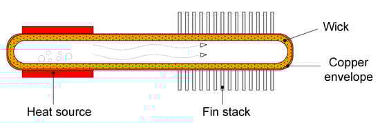
Figure 3.
The construction and principle of operation of a heat pipe.
In a cooling system using heat pipes, three sections need to be identified: the vapor section, the adiabatic section and the condenser section. As is shown in Figure 3, the heat source (e.g., cooled semiconductor device) adheres to the vapor section, where the heat flux causes vaporization of the cooling liquid. As a result of a pressure increase in the vapor section, the vapor travels toward the cooler condenser section, where it cools down and condenses on the wick structure. In this part of a heat pipe, the fin stack occurs, which removes the heat outside the heat pipe and makes it possible to condense the vapor. As a result of capillary action and gravitational force, the condensed liquid returns to the vapor section. In order to make the heat dissipation in the condenser section more efficient, heat pipes typically work with heat sinks, e.g., in the form of a stack of thin copper or aluminum plates. A further increase of the heat dissipation from the condenser section is typically achieved by forcing air convection with a fan [].
Heat pipes are heat superconductors. The temperature distribution along a heat pipe is very uniform, typically not exceeding 2–5 °C. The effective heat thermal conductivity of heat pipes may be as high as 50 kW/(m∙K) up to 100 kW/(m∙K).
A special variation of heat pipes is the loop heat pipe (LHP) [,,,]. In this solution, the ways of travel of vapor and the condensed liquid are different. Due to the differences in the density, the vapor flows over the top of heat pipes, whereas the liquid lies at the bottom of them. Due to this, a further increase of heat transfer is possible. As the name suggests, the system has the shape of a loop, where the directions of travel of the vapor and the condensed liquid are different. Applying a heat source to the evaporator section of an LHP results in the boiling and evaporation of the cooling liquid. The vapor travels to the cooler condenser section, where it turns back into the liquid and returns another way, closing the circulation. The fundamental significance for the efficient operation of the system is a unidirectional Tesla valve located next to the evaporator. The valve blocks the flow of the vapor in the unwanted direction. Thanks to such a solution, a significant improvement of the heat transfer is possible in comparison with heat pipes. Loop heat pipes have been commercially applied to cool the latest generation of cell phones produced by Xiaomi [,]. The producer claims that LHPs allow double cooling capabilities in smartphones in comparison with the currently commonly used vapor chambers []. Additionally, the loop shape of the cooling system leaves more room for the other components such as a battery, camera module, etc. A similar technology under the name of LiquidLoop is employed by Acer for the cooling of their notebooks []. A very important advantage of such a cooling system is the elimination of the issues related to the application of fans; the accumulation of dust over time and noise generation.
3.4. High Conduction Metal Plates
An application of heat pipes is High Conduction Metal Plates (HCMPs). HCMPs are constructed by building heat pipes into canals machined in an aluminum plate. Heat pipes are typically soldered or epoxied to the aluminum. HCMPs can work with single or multiple heat sources and may be used as a part of the enclosure of electronic devices. The heat pipes built in the HCMP can spread the heat evenly on the entire surface of such a plate in the case of natural convection cooling or can transfer the heat to an edge of the plate where a cold rail is located [].
A view of the HCMP distributing the heat to its entire surface is illustrated in Figure 4a, and the view of the HCMP transferring the heat to the cold rail is shown in Figure 4b.
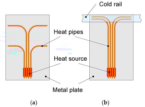
Figure 4.
A general view of a HCMP (a) distributing the heat to the entire plate area, (b) transferring the heat to a cold rail.
As is illustrated in Figure 4a, heat pipes are led from the heat source and bent with certain intervals in order to spread the heat evenly and achieve the largest possible area of heat dissipation. In turn, in Figure 4b it is visible that heat pipes are led close to each other from the heat source to the edge of the plate where they are bent. Such construction allows for effective heat transfer in water-cooled enclosures [].
In the same way as in the HCMP, heat pipes are built into the bases of metal heat sinks in order to achieve better isothermality of the base and better heat dissipation efficiency.
3.5. Vapor Chambers
Vapor chambers are passive two-phase components used in the construction of cooling systems. Vapor chambers operate in a similar way to heat pipes. Applying a heat source to the bottom wall of the vapor chamber causes the cooling fluid to vaporize. The vapors are lifted toward the cooler top wall of the chamber where they condense. The condensed cooling fluid returns to the heat source due to capillary action in the wick and gravity. A typical application of the vapor chamber is to evenly distribute the heat across the base of a local heat sink, to which this chamber adheres. Vapor chambers can also be built into the base of heat sinks in a similar manner as heat pipes. The structure of the vapor chamber allows for the even dispersion of the heat generated by the cooled device in the x-y plane, to the corners and edges of the chamber and the base of the heat sink. Thus, an improvement in the overall heat dissipation efficiency is achieved. Vapor chambers can work with single or multiple heat sources [].
Vapor chambers are manufactured as classic, more expensive two-piece devices and as cheaper one-piece devices (so-called hybrid vapor chambers). The structure of the two-piece vapor chamber is shown in Figure 5 [].
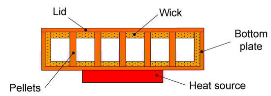
Figure 5.
Construction of a two-piece vapor chamber.
Two-piece vapor chambers are made of metal sheets and pressed into the desired shape, onto which a capillary structure (wick) is applied and column supports (pellets) are attached for mechanical stability. Then, the top and bottom parts of the chamber are joined by diffusion bonding, welding or soldering. Two-piece vapor chambers are produced only in the form of flat devices but can be any shape in the x-y plane. In such vapor chambers, the type and porosity of the wick may be selected and optimized depending on the application. It is also possible to use wicks of a different type and with different porosity in different parts of the vapor chamber.
In turn, the construction of the hybrid one-piece vapor chamber is shown in Figure 6 [].
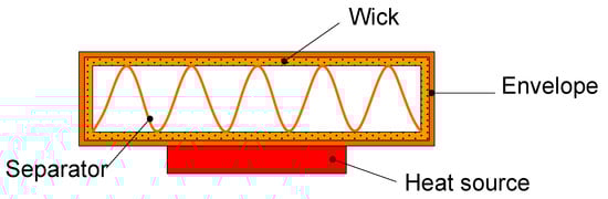
Figure 6.
The construction of a single-piece vapor chamber.
One-piece vapor chambers are produced by flattening a large diameter heat pipe (typically 20–75 mm), into which a metal separator providing mechanical stability is inserted. After that, the vapor chamber is filled up with the cooling fluid and the vacuum is sealed. Such vapor chambers are produced only as rectangular devices, but can be bent, e.g., into a U-shape.
The limitations in the shapes of the produced single-piece and two-piece vapor chambers are connected to technological constraints. One piece vapor chambers are cheaper and do not require stamping or machining in the production process, so the number of secondary operations is significantly reduced. This allows for bringing the cost of production of single-piece vapor chambers down to a level similar to heat pipes []. At the same time, single-piece vapor chambers can be shaped without a significant reduction of thermal performance. The cost of manufacturing two-piece vapor chambers is about 15–30% higher than in the case of single-piece vapor chambers and heat pipes [].
Heat pipes and vapor chambers are, to a certain extent, interchangeable. Replacing several heat pipes with a vapor chamber in the same application allows for obtaining better heat dissipation efficiency, despite the typically lower thermal conductivity of vapor chambers []. Replacing heat pipes with a vapor chamber allows for increasing efficiency of the heat dissipation by 15–30%, but the cost of manufacturing vapor chambers is also higher than the cost of producing heat pipes by about the same percentage [].
Ultra-thin vapor chambers are produced to be used in highly miniaturized devices, e.g., smartphones. Such chambers are produced by etching metal sheets made of copper, steel and titanium [,]. Boyd offers ultra-thin copper vapor chambers with a total thickness of 0.4 mm, as well as the ones made of titanium and steel, which are only 0.3 mm thick []. Such vapor chambers are installed, for example, in Huawei smartphones [].
Conventional vapor chambers are manufactured as independent devices installed between heat sources and heat sinks using thermal interface materials. ACT (Advanced Cooling Technologies) developed a 3 mm thick vapor chamber made of copper-coated ceramics with the thermal expansion coefficient similar to that of silicon []. This allows for direct bonding of semiconductor dies to the vapor chamber. Brazing silicon structures to the vapor chamber reduces thermal resistance of the connection and eliminates the need for mechanical joining of the cooling system components. The semiconductor die can be placed anywhere on the surface of such a vapor chamber [].
In most cases, vapor chambers and heat pipes have thermal conductivity much greater than that of aluminum and copper. A solution similar to the vapor chamber is a liquid chamber, developed and patented by Vapro []. Liquid chambers are manufactured similarly to the two-piece vapor chambers. The main difference is the lack of a wick, as well as the greater amount of cooling fluid filling up the chamber.
Applying a heat source causes the cooling fluid in the chamber to boil and evaporate. The cooling fluid cools down on the chamber top wall and condenses, which causes circulation of the fluid inside the chamber. At the bottom of the liquid chamber, a microporous material is used at the point where heat is removed to ensure greater boiling efficiency. Due to their simpler construction, liquid chambers are cheaper to produce than vapor chambers. Such chambers were used to cool the processors of the Radeon HD 7000 series graphics cards produced by AMD [].
3.6. Thermosiphons
Thermosiphons are passive two-phase cooling components. Thermosiphons operate in a similar manner to heat pipes. The fundamental difference between thermosiphons and heat pipes is the absence of the wick structure inside a thermosiphon. Instead of capillary action, which, in the case of heat pipes, may be gravity assisted, in thermosiphons the transport of the condensed cooling fluid relies only on gravity. Thermosiphons can be divided into two categories: counter-flow thermosiphon and loop thermosiphon [,]. A schematic representation of both the listed types of thermosiphons is shown in Figure 7.
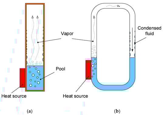
Figure 7.
Schematic representation of (a) counter-flow thermosiphon and (b) loop thermosiphon.
As is visible in Figure 7, the heat from a heat source causes boiling of the fluid inside the thermosiphon. The vapor travels up, where it condenses on the cooler walls of the condenser section. The condensed fluid gravitationally flows back to a pool next to the heat source. In loop thermosiphons, similar to loop heat pipes, the moving directions of vapor and condensed fluid are separated.
Thermosiphons are filled up with a larger amount of the working fluid than the heat pipes. An important limitation of thermosiphons is the necessity of locating the source of heat below the condenser. As a cooling liquid, the following are used: water (most common), ammonia, methanol or some kind of refrigerant [].
3.7. Encapsulated Conductive Plates
Encapsulated Conductive Plates (ECPs) are used to build high-quality electronic devices cases. In the construction of ECPs, sheets of annealed pyrolytic graphite are used. Since graphite is brittle and cannot bear loads, it cannot be a structural element. To overcome these limitations, graphite plates are bonded with sheets of aluminum or copper to form the outer walls of the ECPs [,,,,,,]. The construction of an ECP is shown in Figure 8.
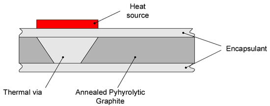
Figure 8.
A cross-section view of a high-conductivity cooling plate.
Graphite sheets are characterized by high in-plane thermal conductivity λ = 1000−1500 W/(m∙K), but their through-plane thermal conductivity is only about 7–10 W/(m∙K) [,,,]. To efficiently use the in-plane thermal properties of graphite sheets in ECPs, it is essential to deliver heat in such a way that it can be conducted in-plane and dissipated over a larger area. For this purpose, metal thermal vias located under heat sources are used. The location of the heat sources must be known at the stage of designing the cooling system using ECPs in order to plan the location of thermal vias. The effective thermal conductivity of ECPs with the external walls made of aluminum is approximately 550 W/(m∙K) []. Pyrolytic graphite in the form of sheets that are not encapsulated is also widely used for cooling modern smartphones, laptops and TV sets [].
3.8. Single-Phase Liquid Cooling
In single-phase liquid systems, the heat from heat sources is removed from the components to be cooled by means of a coolant. In such systems, the coolant does not change its aggregate state. The schematic diagram of a single-phase liquid cooling system is shown in Figure 9.
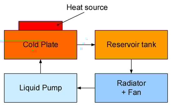
Figure 9.
The block diagram of a single-phase liquid cooling system.
Single-phase liquid cooling systems are constructed of a cold plate or a water block, a pump forcing the flow of a coolant, a radiator and a reservoir tank. Typically, the fan is mounted onto the radiator in order to achieve better heat dissipation. The coolant flows out of the reservoir and reaches the cold plate, where the heat generated in the cooled devices is absorbed by conduction and transported away by forcing the coolant to flow to the radiator, where it releases the heat to the surroundings. Depending on the application, the water block or the cold plate construction may be different. Microchannel and mini-channel structures are used in water blocks, whilst the manifold or serpentine arrangement of channels is used in the case of larger surfaces (cold plates) [].
Aluminum, stainless steel, copper or polymer-based materials are used as cold plate materials. The most commonly used coolants are water, deionized water, water/ethylene glycol mixture and dielectric fluids. For cooling CPUs, single-phase liquid cooling systems operating in a sealed loop with a pump integrated with a water block are often used. These cooling systems are called All-in-One (AiO). Sealing the loop prevents evaporation of the refrigerant and eliminates the need for a reservoir tank. In such solutions, skived copper heatsinks ensuring the microchannel flow of the cooling fluid inside the water block are commonly used [].
An example of a single-phase liquid system dedicated for cooling CPUs is the AiO LIQTECH TR4 II 240, produced by Enermax [].
3.9. Two-Phase Liquid Cooling
Two-phase liquid cooling systems are similar in their construction to single-phase systems. The difference is that in two-phase systems, the coolant boils on the surface of the evaporator in direct contact with the device to be cooled. In such systems, the heat absorbed by the coolant from the heat source is stored in the form of latent heat of vaporization. This heat is then carried away by forcing the flow of the coolant and dissipated in a remote radiator [,]. Low boiling temperature dielectric fluids are used as the working fluid.
Two-phase forced circulation systems, unlike thermosiphons, which use the same physical mechanism, allow for the cooling of electronic components regardless of the spatial orientation. For two-phase systems, the required coolant flow rate is much lower than for single-phase systems. Accordingly, pumps of much lower power and dimension are used. This is especially important for cooling very powerful components, in the order of hundreds of kilowatts.
Two-phase systems are used for cooling devices dissipating power up to 300 kW with the power density above 50 W/cm2. Two-phase forced circulation systems allow for achieving 7 times more efficient heat transfer for the same flow rate compared with the pumped single-phase systems. The use of a two-phase forced circulation system reduces the size of the cooling system by 2/3 in comparison with the equivalent air-cooled systems.
3.10. Immersion Cooling
In immersion electronics cooling systems, the cooled devices are placed in a tank and submerged in a cooling fluid [,,,,,,]. Typically, these are dielectric liquids having low boiling temperature. Immersion cooling systems can be divided into two categories—single phase and two-phase. In single-phase systems, mineral oil can be used as a cooling fluid, whilst in two-phase systems dielectric fluids are used [].
Immersion cooling is most often used for cooling the enterprise servers and the ASIC modules used in the process of cryptocurrencies mining, as well as the enterprise, cloud, telecom and HPC data centers [].
For such devices, immersion cooling is more attractive than air cooling or single-phase liquid cooling. The use of immersion cooling allows for a much better use of space in the data centers, the elimination of fans and a significant reduction in the power required for cooling compared with the solutions using air cooling or water cooling. When replacing water cooling with immersion cooling, the cooling system itself is also simplified, as it is not necessary to use individual water blocks for each heat source and the complicated supply structure [].
In the case of low heat flux values, direct cooling of the power device cases is possible. For higher flux values, simple heat sinks are used, and for the devices with high heat flux density, metal heat spreaders made of copper or aluminum with the boiling enhancing surface are used [].
The advantage of this type of cooling system is that the heat is given off not only by power components, but by all components, including the structure plate of the device. The use of immersion cooling instead of air cooling allows for increasing the cooling efficiency, eliminating fans and reducing the cost of electricity necessary to power the cooling system by 95%.
3.11. PCM Heat Sinks
Another example of the use of latent heat in electronics cooling are heat sinks with a phase change material (PCM). Figure 10 illustrates the principle of operation of such heat sinks.
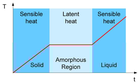
Figure 10.
Principle of operation of PCM heat sinks.
In classic single-phase systems, the temperature increases proportionally to the energy delivered to a cooling system. In two-phase systems, the state changes and the latent heat are used [].
PCM heat sinks are built using paraffin wax or hydrated salts, which change the state of matter from solid to liquid when supplied with sufficient energy. In such systems, the temperature rises proportionally to the energy supplied until the solid begins to melt and remains practically constant over the entire energy range from the beginning of the melting of the solid to its complete liquid transition. By selecting the type of solid and its volume, it is possible to create a situation in which, despite the energy supplied from the cooled device to the cooling system, the temperature of this device will not increase significantly.
The cooling devices considered can absorb heat with a small increase in temperature during the phase transition from solid to liquid. In this transition, the latent heat is very high and even two orders of magnitude higher than the sensible energy stored by the specific heat of a material in its solid or liquid phase. This phenomenon is illustrated in Figure 10, showing a temperature rise of a PCM over time with the steady-state energy input. In technical realization, a PCM is contained in the hermetically sealed enclosure. IT is used to maintain temperatures of the critical heat generating components over a given period of time [].
The applications of PCM, heat sinks include systems having the pulse mode of operation, where the energy is stored during the on state and dissipated during the off state, as well as the systems having the finite mission life as missiles, where PCM heat sinks can replace more complex active thermal solutions.
Due to their ability to store more thermal energy in a smaller package, with less mass when compared with some of the more traditional thermal solutions, PCM heat sinks are also attractive to the booming spacecraft market.
The concept of storing the heat by melting a phase change material is fairly simple; however, there are numerous practical challenges that must be addressed to obtain the volume or mass optimized, the fully functional and highly reliable PCM heat sink design.
The first consideration when designing a PCM heat sink should be the PCM’s melting temperature. Typically, the PCM is selected to provide a melting temperature that is several degrees lower than the maximum component temperature throughout the mission. Paraffin waxes are common because they are available with a wide range of melting temperatures. The second consideration is that the energy that must be stored and the duration. The combination of these two factors, along with thermal properties of the PCM ultimately determines the amount of the PCM required in a cooling system.
The challenge with many PCM heat sink designs is the poor thermal conductivity of the PCM. For example, paraffin waxes typically have thermal conductivities of less than 1 W/(m∙K). This is remedied by adding the internal structures such as fins, heat pipes or metal foams.
3.12. Thermoelectric Modules
Thermoelectric modules are electronic devices built of a matrix of alternating n and p type semiconductor cubes connected in series with metal tracks printed on ceramic plates constituting the outer casing of the module. The resulting n-p thermocouple junctions are connected to one side of the module and the p-n thermocouple junctions to the other. The ceramic case acts as a thermal coupling component for the thermocouple junctions on each side of the module. The structure of the thermoelectric module is shown in Figure 11 [].
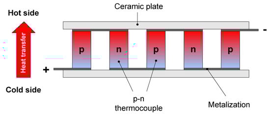
Figure 11.
Construction of a thermoelectric module.
The semiconductor used in the production of thermoelectric modules is usually properly doped bismuth telluride (Bi2Te3), while the cases are made of aluminum oxide (Al2O3) or aluminum nitride (AlN) [,]. Bismuth telluride is used because of its favorable thermoelectric properties and a small energy gap of only 0.16 eV to obtain high reverse current of reverse-biased junctions formed by combining p and n materials. Aluminum oxide and aluminum nitride are used because of their low electrical conductivity and relatively high thermal conductivity.
Thermoelectric modules work on the basis of the Peltier effect. The Peltier phenomenon consists in releasing or absorbing energy under the influence of electric current flowing through the junctions of two metals or semiconductors of the n and p type. In a circuit containing both types of junctions, a temperature difference arises between these junctions. The junction in which the generation of charge carriers takes place is cooled, and the junction in which their recombination takes place is heated. This operation of thermoelectric modules is called pumping the heat from the cold side to the hot side. Hence, the considered modules are called heat pumps.
Thermoelectric modules can be powered by DC voltage or a PWM signal. As a result of the current flow through the module, the power is released, which worsens the properties of the module. As a result, not only the heat absorbed on the cold side of the module, but also the heat released in the module itself, has to be removed from the hot side. For the Peltier module to work efficiently, it is necessary to ensure effective heat dissipation from the hot side of the module, e.g., through a heat sink. Thermoelectric modules are used in the systems requiring precise temperature control and in those where cooling or keeping the temperature below the ambient temperature is required.
3.13. Interface Materials
Interface materials are an important component of cooling systems. These materials are used at the interface between the case of the device to be cooled and the cooling system. The purpose of interface materials is to fill up micro-inequalities and air spaces between the contact planes and to allow for the best possible heat conduction from the device to the cooling system.
Among modern interface materials, the following should be mentioned [,,,,]: thermal greases, gap fillers, insulating hardware materials, thermal pads and films, graphite pads and films, thermal tapes, phase change materials and thermal epoxies. A thermal interface material (TIM) is crucial to every thermal management solution. Depending upon the application, some types of TIM may be preferable over another to help facilitate better performance.
Thermal grease is a semi-liquid compound specially designed to obtain a high value of thermal conductivity. Most thermal greases are based on silicone and include tiny thermally conductive filler particles increasing their thermal conductivity. There are also silicone-free greases used for the applications that concern wettability and adhesion of the surfaces, which may come in contact with thermal grease.
Greases are a type of pseudo fluid. Therefore, the pressure applied to the thermal grease between two surfaces makes it possible for it to shear and spread thin between those surfaces. The thinner the greases layer, the less thermal resistance of the interface material can be obtained. Therefore, thermal greases are the ideal thermal interface for flat and smooth surfaces. Such a thermal interface requires spring-loaded mounting forces. With an increase in temperature, these greases can flow and thin out. To obtain the high quality of thermal contact, a springy force should be used to mount the greased surfaces. Unfortunately, thermal greases have a tendency to dry out after much use.
In turn, gap fillers are elastomeric sheets, typically made of silicone containing specialized thermal filler material. These materials increase the thermal conductivity of the gap fillers. They are produced in different kinds that can be used for a specific application. Such interface materials are cut to standard device sizes, or they have customized shapes.
All gap fillers contain a base elastomer and a thermal filler mixed in including silicone or silicone free materials. Some of these materials can electrically isolate hot devices, whereas others can absorb electromagnetic interference.
A thermal interface material is typically used due to its high thermal conductivity and electrical resistivity. Thermal interface insulating material is known for mechanical stability and a wider range of the operation temperature compared with other TIMs.
Thermally conductive ceramics, e.g., aluminum oxide, aluminum nitride and beryllium oxide are commonly used since they are affordable and easy to manufacture in discrete semiconductor devices. Mica has a sheet-like structure with excellent conductivity. It is widely available and easy to process. Therefore, mica is a popular material in applications, where electrically insulating yet thermally conductive are needed. Such interfaces can also be manufactured from plastics such as nylon, PTFE-filled acetal or diallyl phthalate. Plastics that are used for insulating semiconductor devices require high dielectric strength and good thermal and chemical stability. Ceramics need to be prepared for the dedicated device and must include proper lead and mounting holes.
Thermal pads and films are thin materials used to conduct the heat from one surface to another. The majority of thermal pads and films belong to flexible materials. They are typically made of a higher durometer silicone-based material than gap fillers. Silicone pads are doped with more conductive materials, such as aluminum oxide or boron nitride. Typically, thermal pads are reinforced by fiberglass to increase tear resistance of the material.
Thermal films (frequently called Kapton) are commonly made of polyimide of high electrical resistivity. They can be also made from other materials, such as graphite. Not all thermal pads and films are considered electrically insulating. They are very popular because of their flexibility, light weight and because they are extremely thin.
Graphite pads are made of a stack of graphene sheets; therefore, they are characterized by high electrical and thermal conductivity. While excellent when it comes to spreading heat along its plane, graphite films are relatively delicate and brittle compared with other films and pads. Graphite materials can be used at temperatures beyond 200 °C.
Thermal tapes are adhesive on one or both sides. They are placed on a liner or a carrier to keep them in a sheet or a roll before they make their way to the application. Thermal tapes can reduce the need to mount the hardware for smaller devices and heat sinks.
A phase change material is composed of a wax substance that has a melting temperature between 50–65 °C. While the material is transitioning from solid to liquid, its temperature stays consistently at its melting temperature as it absorbs heat. This provides excellent temperature control between the connected surfaces. Once the phase change material absorbs its latent heat of fusion, the energy it takes to completely melt the solid, then it starts increasing its temperature while in the liquid state. Many phase change materials are deposited onto a highly thermally conductive base material, e.g., a heat-sink.
When a phase change material is heated up past a specific temperature, it melts and flows into any existing nooks and crannies between the surfaces it is between. So, after the first heating, the phase change material melts and the low thermal resistance between the surfaces is obtained.
Because the phase change materials turn into liquids, they can get into some tight spaces that other thermal interface materials cannot quite reach. This also means that they can handle rougher surfaces easily. Surfaces with imperfections, rough spots or any surfaces less than perfect could benefit from using the phase change material for the heat transfer. Yet, gap fillers are still the best choice for huge height disparities.
Thermal epoxy is the most robust thermal interface material. Some epoxies use thermally conductive ceramic particles, while others use small metallic particles. Like other epoxies, there are one-part and two-part resins that can be mixed and applied to join the surfaces together.
Epoxy does something that most other thermal interface materials do not. Thermal epoxies create a strong mechanical bond between the surfaces it curls between. This allows for thermal epoxy to both be a thermal interface material and a mounting method. In some cases, this can help reduce the amount of mounting hardware used in a product.
4. Selected Computer Tools Supporting the Designer of Cooling Systems
Some cooling system manufacturers provide cooling system design tools on their websites. Examples of such producers are MHS, ACT and Celsia [,,].
Online calculators for designing active heat-sinks can be found on the websites of MHS [] and Celsia [] and, for designing cooling systems using heat pipes, on the websites of ACT [] and Celsia []. Additionally, ACT offers an online calculator that calculates the temperature profiles of the passive PCM heat sink using 3 selected types of the PCM.
It should be noted that tools of this type are used only for the initial estimation of the parameters of the cooling system. A more precise determination of the values of these parameters requires modeling with the use of CFD (Computational Fluid Dynamics) techniques []. Prototyping and design optimization are also common practices when designing cooling systems for series production.
This section describes Celsia’s tools for designing a cooling system using a forced air fin (fin stack) radiator [] and a cooling system using heat pipes []. A heat sink calculator allows for calculating the required heat sink volume and the dimensions based on the power input, the maximum case temperature, the ambient temperature and the available air flow. Calculations are performed according to the following equation:
where V is the volume of the designed heat sink, P is the power dissipated in the cooled device, RV is volumetric thermal resistance and ΔT = Tcmax − Tamax is the so-called thermal budget. The thermal budget is assumed by designers of a cooling system, and it is equal to the maximum allowable difference between the device case temperature and the maximum allowable ambient temperature. Volumetric thermal resistance is a parameter of a value selected based on the available cooling air speed according to Table 1 [].

Table 1.
Volumetric thermal resistance for selected values of the air flow.
For heat sinks of a volume smaller than 300 cm3, it is recommended to use a lower limit of RV, while for large heat sinks greater than 1000 cm3, the upper limit should be used. Designing is an iterative process and the selected RV value may be fine-tuned based on the heat sink volume obtained in the previous iteration. For the heat sinks that must work at high altitude, the RV value must be lowered. A solid rule of thumb is 10% for every mile of altitude.
A model used for calculations assumes that the fin design is optimized for a given air flow. The estimated heat sink volume calculated using the calculator being described should fit within ±15% of a final design []. This tool is useful during the early design phase. For the ΔT values less than 40 °C, the use of two-phase cooling should be considered.
4.1. Heat Sink Performance Calculator
A heat sink performance calculator allows for determining and comparing parameters of an active heat sink made of a stack of fins with a base made of solid metal and with a vapor chamber built in its base. Selection of the heat sink in the form of a fin pack was dictated by the fact that fin packs (zipper fins) are often used with two-phase devices, instead of extruded, machined, bonded or skived heat sinks.
A general view of the designed heats sink is shown in Figure 12.
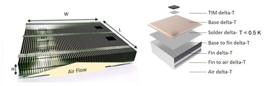
Figure 12.
Construction of the designed heat sink.
The calculator allows for selecting the heat source location in the center of the heat sink base or in one of the corners. The input variables include the details of a heat source (power, length, width), a heat sink base (length, width, thickness, material), a fin pack (height, thickness, spacing, air flow, material), the ambient temperature and the TIM selection. Both the base and the fins can be selected to be made of either aluminum or copper. The selection of the base thickness for both a vapor chamber and a metal base is limited to three values—3 mm, 3.5 mm and 4 mm. The fin thickness can be selected within the range from 0.2 to 0.6 mm with the 0.1 mm step. The base width can be selected from standard values in the range from 12.5 mm to 109 mm. The available TIMs include performance grease, standard grease, thin pad and thick pad. The design tips given by Celsia include the length of the fins, up to 500 mm, while the fin height is between 3 and 100 mm, depending on the fin efficiency. The fin spacing should be at least twice the fin thickness. In the case when the ratio of the heat sink base area to the heat source area surpasses 10:1, the use of a vapor chamber becomes an attractive solution. The model used for calculations assumes zero air flow bypass.
As an output, the user gets the values of heat source area, power density and fin efficiency, as well as detailed results of the thermal analysis, the air temperature difference (∆T), fin to air ΔT, fin ΔT, total fin pack ΔT, fin pack Rth, pressure drop, TIM ΔT and base-fin ΔT. The results also include a comparison of the base ΔT values and the total heat sink ΔT for the base made of a solid metal and with a built-in vapor chamber, as well as thermal conductivity across the “length” of a vapor chamber. This makes it possible to assess which solution meets the design requirements best, especially the thermal budget. ΔT of the solder between the vapor chamber and the base is usually lower than 0.5 °C and is not included in the calculator.
The additional graphical representation of the results of design is a chart illustrating the dependence of a fin stack temperature rise and a pressure drop on the fin thickness in the range 0.2–0.6 mm.
4.2. Heat Pipe Calculator
On the Celsia website, there is also a calculator that allows for designing cooling systems making use of heat pipes. The input for the calculations is the lengths of the heat pipe, the evaporator section, the condenser section and the operating temperature. The operating temperature can be selected from the values in the range from 20 °C to 100 °C with the 20 °C step. Moreover, the user needs to select a wick type. The available types are standard and performance. As a result of calculations, the dependences of power versus the operation angle and ΔT versus power for heat pipes of the diameter from 3 mm to 10 mm are presented in the form of charts and tables. The results allow for selecting the diameter and the number of heat pipes suitable to dissipate the required power, knowing the orientation of the cooling system in its work conditions.
Celsia does not share the information on the equations used in the calculators but provides reference to the literature []. In the cited paper, the classical DC compact thermal model of a cooling system is used.
Additionally, the values of effective thermal conductivity and the minimum thickness of the heat pipes whose performance is negatively affected, are calculated and presented in the table form. The first can be useful as an input value in the case when further modeling with the CFD methods is going to be performed. The other allows for assessing how much the heat pipe can be flattened without lowering its thermal performance.
5. Analysis of the Influence of Selected Factors on the Parameters of Cooling Systems
Using the tools described in Section 4, the calculations of an influence of selected parameters for two cooling systems—heat pipes and an air-cooled active heat sink—were performed. The calculations results are presented in Figure 13, Figure 14, Figure 15 and Figure 16.
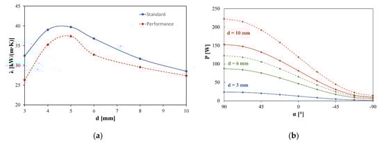
Figure 13.
Dependences of (a) effective thermal conductivity of a heat pipe on its diameter and (b) power capacity of a heat pipe on its orientation.
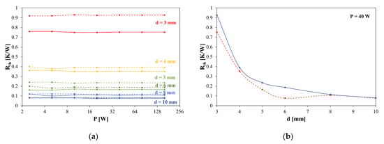
Figure 14.
Dependences of (a) thermal resistance of the heat pipe on power and (b) the heat pipe thermal resistance on its diameter. Standard wick are marked with solid lines and performance wick with dashed lines.
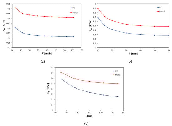
Figure 15.
Dependences of thermal resistance of the designed heat sink on (a) cooling air volume, (b) fin height, (c) fin and heat sink base length.
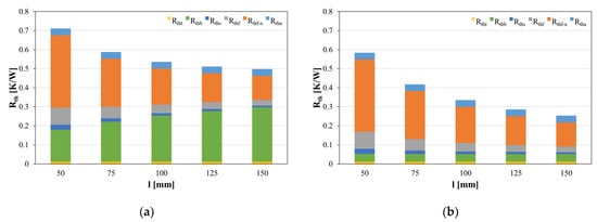
Figure 16.
Dependences of the overall thermal resistance of the designed heat sink and its components on the base length for (a) metal base, (b) vacuum chamber base.
In Figure 13 and Figure 14, the dependences of effective thermal conductivity of a heat pipe λ on its diameter d and power capacity p of a heat pipe on its orientation are shown. In Figure 14b, the value of the angle α represents the orientation of the heat source in relation to the condenser. The α = 90° means that the condenser is located exactly above the heat source. The flow of the condensed fluid in this orientation is gravitationally assisted. The value α = −90° means that the heat source is located above the condenser. Is such a situation, the flow of the condensed fluid relies entirely on the capillary force. The calculations were made for pipes of various diameters, ranging from 3 to 10 mm, 200 mm long, the evaporation section length 25 mm, the condensation section length 75 mm, the operating temperature 60 °C and for two types of a wick—standard and performance. In the figures, the results over the standard wick are marked with solid lines, whereas the results over the performance wick are marked with dashed lines.
As is seen in Figure 13a, the dependence of effective thermal conductivity of a heat pipe on its diameter is a strongly nonlinear and non-monotonic function. The best thermal conductivity was obtained for heat pipes of the diameter equal to 4 and 5 mm. Both increasing and decreasing the heat pipe diameter from these values led to a drop in the λ value. Surprisingly, the selection of a performance wick over the standard wick caused a decrease in the effective thermal conductivity.
As shown in Figure 13b, the power capacity of a heat pipe strongly depends on its spatial orientation. The best efficiency is obtained when the evaporator is placed directly above the heat source. Changing the slope of the heat pipe reduced the efficiency of the cooling system.
Figure 14 presents the dependencies of thermal resistance of a heat pipe on the dissipated power p and the heat pipe thermal resistance on its diameter.
As is visible in Figure 14a, thermal resistance of the heat pipe depends strongly on its diameter but remains constant within the whole range of the analyzed power. Thermal resistance is a decreasing nonlinear function of the diameter of the heat pipe, as is shown in Figure 14b for a selected power of 40 W.
In turn, in Figure 15 the dependences of thermal resistance of the designed heat sink on the volume of the air flowing through the heat sink per hour V, the fins height h and the heat sink base length l are presented. The length of the heat sink base is the same as the fin length. In Figure 15, the results obtained for the designed heat sink with a metal base and a vapor chamber are compared. The results for the metal base are marked with red color, whereas those for the vapor chamber are marked with blue color.
The calculations were performed for a heat source of the dissipated power p = 100 W and the dimensions 25 mm × 25 mm, located in the center of the heat sink base. Aluminum was selected as the material for the heat sink base and fins. The heat sink base width was assumed to be 76 mm, and the base thickness was equal to 3.5 mm. The selected fins thickness was 0.6 mm and the distance between the fins was 1.8 mm. The maximum ambient temperature was assumed to be 35 °C. As a TIM, performance grease was chosen in the calculator options.
As is visible in Figure 15, the use of the vapor chamber significantly reduces thermal resistance of the designed heat sink in comparison with the heat sink with the aluminum base.
Figure 16 illustrates the dependences of the total thermal resistance of the designed heatsink and individual components of the heat flow path on the length of the heat sink base, for the metal base (Figure 16a) and the vapor chamber (Figure 16b). Yellow color marks thermal resistance of the interface material Rtht, green color the thermal resistance of the heat sink base Rthb, navy blue color the thermal resistance of the solder connecting the heat sink base with the fin pack Rths, gray color the thermal resistance of the fins Rthf, orange color the thermal resistance between the fins and the ambient Rthf-a and blue color the thermal resistance of the air Rtha.
As is visible in Figure 16, in both the analyzed cases, the total thermal resistance of the heat sink decreases with the extension of the heat sink base. In the case of a heat sink with the metal base, Rthb and Rthf-a have the largest share in the total thermal resistance of the designed heat sink, and in the case of using the vapor chamber, it is Rthf-a. As can be seen in Figure 16a,b, in the entire considered range of the base length l, Rth of the vapor chamber is much lower than Rth of the metal base of the heat sink. In addition, Rth of the vapor chamber is constant despite Rth of the metal base, which increases more than 50% with an increase in l. In the case of the metal base, this increase is compensated for a decrease in Rth associated with the beneficial effect of increasing the base length l on Rthf-a.
6. Comparison of Properties of Selected Cooling Systems
The previous papers by the authors [,] presented the results of the investigations on cooling systems for selected electronic components. These papers show that through the appropriate selection of a cooling system, it is possible to improve the efficiency of the heat removal from a semiconductor device even several dozen times. Figure 17 shows the measured dependences of thermal resistance on the dissipated power for power MOSFETs with the TO-220 type case operating in different cooling systems marked successively with letters from A to H. The investigations were carried out using the following cooling systems described in []:
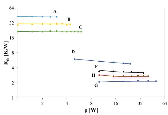
Figure 17.
Measured dependences Rth (p) for selected cooling systems of power MOSFETs.
- A.
- Transistors with no additional cooling components,
- B.
- Fan with transistors placed on the intake side,
- C.
- Fan with transistors placed on the exhaust side,
- D.
- Extruded heat sink made of aluminum,
- E.
- Extruded heat sink with a fan,
- F.
- Heat pipes with the aluminum heat sink,
- G.
- Heat pipes with the aluminum heat sink and two fans in the push-pull configuration,
- H.
- Liquid cooling system.
As can be seen, the use of the appropriate cooling system enables reducing the thermal resistance value from over 40 K/W to only 2 K/W, which is only 1 K/W higher than the thermal resistance declared by the manufacturer between the semiconductor die and the case. The influence of power p on the value of Rth depends on the cooling system used.
Figure 18 shows the effect of the fan rotation speed ω on the thermal resistance of the considered transistor operating in a selected cooling system.
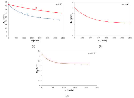
Figure 18.
The measured dependences Rth (ω) for cooling systems (a) B and C, (b) system E and (c) system G.
Figure 18 indicates that an increase in the fan rotation speed causes a significant decrease in Rth. For systems B and C, this change amounts to 30%, for system E—50%, and for system G—30%.
Table 2 summarizes the values of the parameters characterizing selected components of cooling systems, particularly the components used in the systems containing heat pipes [].
Table 2.
Values of parameters characterizing selected components of cooling systems.
As can be seen, the cheapest solution is to use aluminum and a spot heat pipe, and the most expensive is encapsulated conduction. The maximum power density released in the cooled element is the highest for the vapor chamber and reaches 750 W/cm2, the maximum height is reached by the HCMP plate (about 50 cm). The presented data can make the selection of construction heat pipes of the needed cooling efficiency easier.
Figure 19 shows the results of measurements illustrating the influence of the supply current of the thermoelectric module iP and the supply voltage of the heat sink on the thermal resistance of the cooled device []. The cooling system includes a thermoelectric module, a heat sink and a fan. The fan used for the investigations has the following dimensions: W80 × L80 × H25 mm; the rated supply voltage is equal to 12 V. The heat-sink is made of black anodized aluminum and has the following dimensions: W29 mm × L20 mm × L11.5 mm. The thermoelectric module has the following dimensions: W15 × L15 × H3.7 mm.
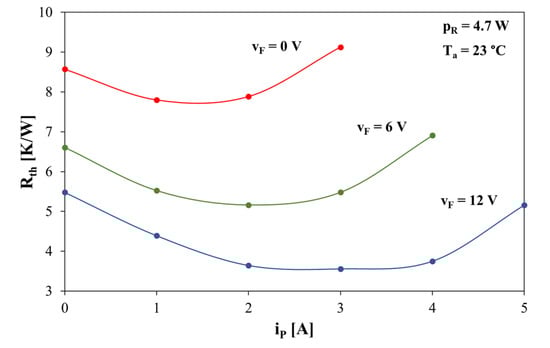
Figure 19.
Dependences of thermal resistance Rth of the cooling system with the Peltier module on its feeding current iP.
As is visible, the best cooling conditions in the cooling system with the Peltier module can be achieved when the heat is efficiently removed from its hot side and the module current is optimal. At an appropriately selected capacity of the Peltier module and the module current iP, it is possible to bring down the temperature of the device being cooled down below the ambient temperature, which may be important in some applications, e.g., detectors of infrared or cooling systems of microprocessors.
The improper selection of current ip may cause worsening of the cooling efficiency and an increase in Rth. Such operating conditions may lead to an increase in the temperature of the hot side of the Peltier module above the case temperature of the device being cooled.
In [], the selected properties of two-phase cooling technologies are compared. In Table 3, selected properties of such technologies are compared. In this table, the numbers denote the position in the ranking of the cooling systems considered. In this ranking, number 1 denotes excellent, whereas 5 denotes fair.
Table 3.
A comparison of selected properties of two-phase cooling technologies.
Analyzing the data presented in Table 3, it is easy to observe that the most effective heat removal can be obtained using immersion cooling, but it is characterized by the smallest system dependency. Good parameter values can be also obtained for thermosiphons and vapor chambers. On the other hand, the cheapest, most universal and of the smallest efficiency are fin heat sinks.
In turn, on the website [], selected properties of different cooling systems are compared. The information given on the cited website is presented in Table 4.
Table 4.
A comparison of selected properties of selected cooling technologies.
As is visible in Table 4, many properties decide which cooling method is the best for the applications considered. As can be seen, the cheapest and of the lowest efficiency cooling systems use air cooling. On the other hand, the most effective cooling can be obtained in pumped two phase cooling systems, but their cost is the highest. The big advantage of such systems is also the possibility of its easy expansion for cooled devices characterized by a high value of the dissipated power. Energy efficiency is the highest for air cooling and the two-phase air, which do not require a power supply.
7. Final Remarks
This paper describes selected issues related to cooling systems of semiconductor devices. The classification of cooling systems is presented. The basic components of such systems are discussed. The description includes such classical elements of cooling systems as heat sinks, fans and thermoelectric modules. Modern constructions including vapor chambers, heat-pipes, thermosiphons, encapsulated conduction plates, single-phase liquid cooling and PCM heat sinks are also described. The possibilities of using various interface materials in cooling systems are indicated.
Typically, a cooling system comprises at least two of the listed components. The design theory of the cooling system is to properly select such components and ensure dissipation of the heat generated in the cooled device while limiting the maximum value of the junction temperature of this device. The tools described in this paper, provided by the manufacturers of cooling systems, may be useful in this task.
The presented results of calculations and measurements show that the efficiency of heat removal in semiconductor devices, which is characterized by thermal resistance, depends on the following: the design of the cooling system, the value of the power dissipated in the cooled device, the size of the heat pipes, the dimensions of a heat sink used and the air flow velocity around the heat sink. It is shown in the specific examples that changes of the mentioned factors can cause even 20-fold changes in the value of thermal resistance of the cooled device.
When designing a cooling system, it is worth remembering that lowering the junction temperature of a semiconductor device by 8–10 K makes it possible to double its lifetime []. The considerations presented in this paper provide the current information on the solutions for cooling systems of semiconductor devices. This scope of knowledge is currently being intensively developed and it can be expected that soon there will be new designs of such systems enabling efficient removal of the heat from the devices operating at much higher values of power density. This development is necessary from the point of view of the needs of both microelectronics and power electronics.
This study is devoted to components used in cooling systems of semiconductor devices. Of course, the problem of effective cooling is also important for other components of electric equipment. Due to the limited length of this article, we did not consider, however, such a problem in this study. More information about the problem of cooling batteries is given in [,,,], heat sinks dedicated for power LEDs in [] and the systems dedicated to cooling the data centers in [].
Author Contributions
Conceptualization, K.G.; methodology, K.G. and K.P.; validation, K.G. and K.P.; investigation, K.P.; writing—original draft preparation, K.G. and K.P.; writing—review and editing, K.G. and K.P.; visualization, K.P.; supervision, K.G. All authors have read and agreed to the published version of the manuscript.
Funding
The project financed within the program of the Ministry of Science and Higher Education called “Regionalna Inicjatywa Doskonałości” in the years 2019–2022, the project number 006/RID/2018/19, the sum of financing 11,870,000 PLN.
Institutional Review Board Statement
Not applicable.
Informed Consent Statement
Not applicable.
Data Availability Statement
Data available for request.
Conflicts of Interest
The authors declare no conflict of interest.
Nomenclature
| ACT | Advanced Cooling Technologies |
| CFD | Computational Fluid Dynamics |
| d | diameter of a heat pipe [m] |
| ECP | Encapsulated Conductive Plate |
| FEM | Finite Element Method |
| h | fin height [m] |
| HCMP | High Conduction Metal Plate |
| iP | Peltier module current [A] |
| l | fin length [m] |
| LHP | Loop Heat Pipe |
| MTTF | Mean Time to Failure [h] |
| PCM | Phase Change Material |
| PWM | Pulse Width Modulation |
| TIM | Thermal Interface Material |
| P | dissipated power [W] |
| Rth | thermal resistance [K/W] |
| Rtha | thermal resistance of the air [K/W] |
| Rthb | thermal resistance of the heat sink base [K/W] |
| Rthf | thermal resistance of the fins [K/W] |
| Rthf-a | thermal resistance between the fins and the ambient [K/W] |
| Rths | thermal resistance of the solder connecting the heat sink base with the fin pack [K/W] |
| Rtht | thermal resistance of the interface material [K/W] |
| RV | volumetric thermal resistance [K/(W·m3)] |
| Tjmax | maximum junction temperature |
| V | volume [m3] |
| v | cooling air volume [m3/h] |
| vF | supply voltage of the fan [V] |
| ∆T | thermal budget [K] |
| λ | thermal conductivity [W/(m·K)] |
| ω | fan rotation speed [1/min] |
References
- Perret, R. Power Electronics Semiconductor Devices; John Wiley & Sons: Hoboken, NJ, USA, 2009. [Google Scholar]
- Avenas, Y.; Dupont, L.; Khatir, Z. Temperature measurement of power semiconductor devices by thermo-sensitive electrical parameters—A review. IEEE Trans. Power Electron. 2012, 27, 3081–3092. [Google Scholar] [CrossRef] [Green Version]
- Górecki, P.; Górecki, K. Methods of Fast Analysis of DC-DC Converters—A Review. Electronics 2021, 10, 2920. [Google Scholar] [CrossRef]
- Vassighi, A.; Sachdev, M. Thermal and Power Management of Integrated Circuits; Springer Science + Business Media: New York, NY, USA, 2006. [Google Scholar]
- De Mey, G.; Kos, A.; Górecki, K. Optimal temperature regulation of integrated circuits with Peltier heat pumps. Energies 2022, 15, 1125. [Google Scholar] [CrossRef]
- Pietruszka, A.; Górecki, P.; Wroński, S.; Illés, B.; Skwarek, A. The Influence of Soldering Profile on the Thermal Parameters of Insulated Gate Bipolar Transistors (IGBTs). Appl. Sci. 2021, 11, 5583. [Google Scholar] [CrossRef]
- Myśliwiec, M.; Kisiel, R.; Guziewicz, M. Materials and technological aspects of high-temperature SiC device packages reliability. Microelectron. Int. 2015, 32, 143–148. [Google Scholar] [CrossRef]
- Górecki, K.; Posobkiewicz, K. Selected problems of power MOSFETs thermal parameters measurements. Energies 2021, 14, 8353. [Google Scholar] [CrossRef]
- Tang, H.; Tang, Y.; Wan, Z.; Li, J.; Yuan, W.; Lu, L.; Li, Y.; Tang, K. Review of applications and developments of ultra-thin micro heat pipes for electronic cooling. Appl. Energy 2018, 223, 383–400. [Google Scholar] [CrossRef]
- Bulut, M.; Kandlikar, S.G.; Sozbir, N. A Review of Vapor Chambers. Heat Transf. Eng. 2019, 40, 1551–1573. [Google Scholar] [CrossRef]
- Posobkiewicz, K.; Górecki, K. Influence of selected factors on thermal parameters of the components of forced cooling systems of electronic devices. Electronics 2021, 10, 340. [Google Scholar] [CrossRef]
- Górecki, K.; Zarębski, J. Modeling the influence of selected factors on thermal resistance of semiconductor devices. IEEE Trans. Compon. Packag. Manuf. Technol. 2014, 4, 421–428. [Google Scholar] [CrossRef]
- Górecki, K.; Górecki, P. Nonlinear Compact Thermal Model of the IGBT Dedicated to SPICE. IEEE Trans. Power Electron. 2020, 35, 13420–13428. [Google Scholar] [CrossRef]
- Górecki, P. Compact Thermal Modeling of Power Semiconductor Devices with the Influence of Atmospheric Pressure. Energies 2022, 15, 3565. [Google Scholar] [CrossRef]
- Gorecki, K.; Dziurdzia, B.; Ptak, P. The influence of a soldering manner on thermal properties of LED modules. Solder. Surf. Mt. Technol. 2018, 30, 81–86. [Google Scholar] [CrossRef]
- Schweitzer, D.; Ender, F.; Hantos, G.; Szabo, P.G. Thermal transient characterization of semiconductor devices with multiple heat-sources—Fundamentals for a new thermal standard. Microelectron. J. 2015, 46, 174–182. [Google Scholar] [CrossRef]
- Catalano, A.P.; Scognamillo, C.; d’Alessandro, V.; Castellazzi, A. Numerical Simulation and Analytical Modeling of the Thermal Behavior of Single- and Double-Sided Cooled Power Modules. IEEE Trans. Compon. Packag. Manuf. Technol. 2020, 10, 1446–1453. [Google Scholar] [CrossRef]
- Chang, Y.; Li, W.H.; Luo, H.Z.; He, X.N.; Iannuzzo, F.; Blaabjerg, F.; Lin, W.X. A 3D Thermal Network Model for Monitoring Imbalanced Thermal Distribution of Press-Pack IGBT Modules in MMC-HVDC Applications. Energies 2019, 12, 1319. [Google Scholar] [CrossRef] [Green Version]
- Górecki, K.; Zarębski, J.; Górecki, P.; Ptak, P. Compact thermal models of semiconductor devices—A review. Int. J. Electron. Telecommun. 2019, 65, 151–158. [Google Scholar]
- Zając, P.; Napieralski, A. Novel thermal model of microchannel cooling system designed for fast simulation of liquid-cooled ICs. Microelectron. Reliab. 2018, 86, 245–258. [Google Scholar] [CrossRef]
- Scognamillo, C.; Catalano, A.P.; Lasserre, P.; Duchesne, C.; d’Alessandro, V.; Castellazzi, A. Combined experimental-FEM investigation of electrical ruggedness in double-sided cooled power modules. Microelectron. Reliab. 2020, 114, 113742. [Google Scholar] [CrossRef]
- Zweben, C. Advanced Thermal Materials and Applications. Electronics Cooling. Webinar. Available online: https://www.youtube.com/watch?v=IEnypVv_FiU&list=WL&index=34&t=845s (accessed on 19 June 2022).
- Zweben, C. Advanced Composite Thermal Management Materials and Applications. Electronics Cooling. Webinar. Available online: https://www.youtube.com/watch?v=KergX0SEflU (accessed on 19 June 2022).
- Zweben, C. Advanced Carbon-Based Thermal Management Materials and Applications. Electronics Cooling. Webinar. Available online: https://www.youtube.com/watch?v=zgRpuTctOAE (accessed on 19 June 2022).
- Liebhard, J.H., IV; Liebhard, J.H., V. A Heat Transfer Textbook, 3rd ed.; Phlogiston Press: Cambridge, MA, USA, 2008. [Google Scholar]
- Yener, Y.; Kakac, S. Heat Conduction; Taylor &Francis: Boca Raton, FL, USA, 2008. [Google Scholar]
- Boyd Web-Site. Available online: www.boydcorp.com (accessed on 19 June 2022).
- Advanced Cooling Technologies Web-Site. Available online: www.1-act.com (accessed on 19 June 2022).
- Celsia Making Hot Technology Cooler. Available online: https://celsiainc.com (accessed on 19 June 2022).
- Living in Comfort Zaward. Available online: www.zaward.com/en/index.php (accessed on 19 June 2022).
- Welcome to MyHeatSinks. Available online: www.myheatsinks.com (accessed on 19 June 2022).
- Advanced Computational Methods & Modeling. Available online: https://www.1-act.com/innovations/advanced-modeling/ (accessed on 19 June 2022).
- Custom Heatsink. Available online: https://celsiainc.com/custom-heatsink/ (accessed on 19 June 2022).
- Computer Based Thermal Simulation for Optimal Cooling Concepts. Fisher Elektronik. Available online: https://www.fischerelektronik.de/fileadmin/fischertemplates/download/NEUHEITEN/waermesimulation_E.pdf (accessed on 19 June 2022).
- Poppe, A. Simulation of LED based luminaires by using multi-domain compact models of LEDs and compact thermal models of their thermal environment. Microelectron. Reliab. 2017, 72, 65–74. [Google Scholar] [CrossRef]
- Lasance, C.J.; Poppe, A. Thermal Management for LED Applications; Springer Science + Business Media: New York, NY, USA, 2014. [Google Scholar]
- Górecki, K. Modelling mutual thermal interactions between power LEDs in SPICE. Microelectron. Reliab. 2015, 55, 389–395. [Google Scholar] [CrossRef]
- d’Alessandro, V.; Rinaldi, N. A critical review of thermal models for electro-thermal simulation. Solid-State Electron. 2002, 46, 487–496. [Google Scholar] [CrossRef]
- Codecasa, L.; Catalano, A.P.; d’Alessandro, V. A priori Error Bound for Moment Matching Approximants of Thermal Models. IEEE Trans. Compon. Packag. Manuf. Technol. 2019, 9, 2383–2392. [Google Scholar] [CrossRef]
- d’Alessandro, V.; Codecasa, L.; Catalano, A.P.; Scognamillo, C. Circuit-Based Electrothermal Simulation of Multicellular SiC power MOSFETs using FANTASTIC. Energies 2020, 13, 4563. [Google Scholar] [CrossRef]
- Catalano, A.P.; Riccio, M.; Codecasa, L.; Magnani, A.; Romano, G.; d’Alessandro, V.; Maresca, L.; Rinaldi, N.; Breglio, G.; Irace, A. Model-Order Reduction Procedure for Fast Dynamic Electrothermal Simulation of Power Converters. Appl. Electron. Pervading Ind. Environ. Soc. 2017, 512, 81–87. [Google Scholar]
- De Mey, G.; Kos, A. The Influence of an Additional Sensor on the Microprocessor Temperature. Energies 2020, 13, 3156. [Google Scholar] [CrossRef]
- Janicki, M.; Ptak, P.; Torzewicz, T.; Górecki, K. Compact Thermal Modeling of Modules Containing Multiple Power LEDs. Energies 2020, 13, 3130. [Google Scholar] [CrossRef]
- Raszkowski, T.; Zubert, M. Analysis of Algorithm Efficiency for Heat Diffusion at Nanoscale Based on a MEMS Structure Investigation. Energies 2020, 13, 2520. [Google Scholar] [CrossRef]
- Raszkowski, T.; Zubert, M. Investigation of Heat Diffusion at Nanoscale Based on Thermal Analysis of Real Test Structure. Energies 2020, 13, 2379. [Google Scholar] [CrossRef]
- Ziegeler, N.J.; Nolte, P.W.; Schweizer, S. Optimization-Based Network Identification for Thermal Transient Measurements. Energies 2021, 14, 7648. [Google Scholar] [CrossRef]
- Castellazzi, A.; Kraus, R.; Seliger, N.; Schmitt-Landsiedel, D. Reliability analysis of power MOSFET’s with the help of compact models and circuit simulation. Microelectr. Reliab. 2002, 42, 1605–1610. [Google Scholar] [CrossRef]
- Ciappa, M.; Carbognami, F.; Cora, P.; Fichtner, W. A novel thermomechanics-based lifetime prediction model for cycle fatigue failure mechnisms in power semiconductors. Microelectron. Reliab. 2002, 42, 1653–1658. [Google Scholar] [CrossRef]
- Thermal Management Solutions, Two-Phase Cooling. Available online: https://info.boydcorp.com/hubfs/Thermal/Two-Phase-Cooling/Two-Phase-Cooling-Technologies-Datasheet.pdf (accessed on 19 June 2022).
- Cooler Master, MasterLiquid ML360 SUB-ZERO. Available online: https://www.coolermaster.com/catalog/coolers/cpu-liquid-coolers/masterliquid-ml360-sub-zero/ (accessed on 19 June 2022).
- EK-QuantumX Delta TEC EVO. Available online: https://www.ekwb.com/custom-loop/quantumx-delta-tec-sub-ambient-cooling/ (accessed on 19 June 2022).
- HEX 2.0. Available online: https://www.phononic.com/support (accessed on 19 June 2022).
- Intel LGA 2011/2066-CPU AIR Cooler with Aluminum Cooling Fins and 35MM Copper Base/TDP 130W. Available online: https://www.titan-cd.com/en/product/Intel-LGA-20112066-CPU-Air-Cooler-with-Aluminum-Cooling-Fins-and-35mm-Copper-Base-TDP-130W/TTC-NA43TZ_RPW_CU35.html (accessed on 19 June 2022).
- Why Pure Aluminum? Available online: https://myheatsinks.com/why-pure-aluminum/ (accessed on 19 June 2022).
- Fisher Elektronik Corp. Technical Introduction. Available online: https://www.fischerelektronik.de/fileadmin/fischertemplates/download/Katalog/technischeerlaeuterungen_e.pdf (accessed on 19 June 2022).
- Zaward Corporation. Ceramic Heat Sink. Available online: https://www.zaward.com/en/product_hs_cat.php?c=8 (accessed on 19 June 2022).
- Zaward Corporation. Zaward’s Ceramic Heat Sink. Available online: https://www.zaward.com/newsletter/52-Zawards_Ceramic_Heat_Sink.php (accessed on 19 June 2022).
- Zaward Corporation. Polymer Heat Sink. Available online: https://www.zaward.com/en/product_hs_cat.php?c=11 (accessed on 19 June 2022).
- Davies, T.W. Thermal Conductivity Values. Available online: https://www.thermopedia.com/content/1187/ (accessed on 19 June 2022). [CrossRef]
- Boyd Heat Sink Fabrications Guide, A Quick & Easy Guide to Choosing a Heat Sink. Available online: https://info.boydcorp.com/hubfs/Resources/Resource-Center/Boyd-Guide-to-Heat-Sink-Fabrications-2020-Technical-Paper.pdf (accessed on 19 June 2022).
- Zaward Thermal Technology Insights, 12. Golf Fan Series. Zaward Inc. Available online: https://www.zaward.com/newsletter/12-Golf_Fan.php (accessed on 19 June 2022).
- Celsia Corp. Heat Pipe. Available online: https://celsiainc.com/technology/heat-pipe/ (accessed on 19 June 2022).
- Shioga, T.; Mizuno, Y. Micro loop heat pipe for mobile electronics applications. In Proceedings of the 2015 31st Thermal Measurement, Modeling & Management Symposium (SEMI-THERM), San Jose, CA, USA, 15–19 March 2015; IEEE: Piscataway, NJ, USA, 2015; pp. 50–55. [Google Scholar] [CrossRef]
- Fujitsu Develops Thin Cooling Device for Compact Electronics. Fujitsu Laboratories Ltd. 2015. Available online: https://www.fujitsu.com/global/about/resources/news/press-releases/2015/0312-01.html (accessed on 19 June 2022).
- Xiaomi Corp. Xiaomi Introduces Loop LiquidCool Technology. 2021. Available online: https://www.mi.com/global/discover/article?id=2571 (accessed on 19 June 2022).
- Acer Corp. Acer LiquidLoop Dust-Free and Noiseless Cooling. Available online: https://www.acer.com/ac/en/US/content/acerdesign-liquidloop (accessed on 19 June 2022).
- Xiaomi Global Communities. Available online: https://xiaomi-mi.com/smartphones/ (accessed on 19 June 2022).
- Advanced Cooling Technologies Corp. HIK Plates. Available online: https://www.1-act.com/when-to-use-heat-pipes-hik-plates-vapor-chambers-and-conduction-cooling/hik-plates/ (accessed on 19 June 2022).
- Celsia Corp. Vapor Chamber. Available online: https://celsiainc.com/technology/vapor-chamber/ (accessed on 19 June 2022).
- Ultra Thin Vapor Chambers. Available online: https://www.boydcorp.com/thermal/two-phase-cooling/vapor-chambers/ultra-thin-vapor-chambers.html (accessed on 10 May 2020).
- News/Ultra Thin Vapor Chamber. Available online: https://trivision-etch.com/ultra-thin-vapor-chamber-2 (accessed on 3 June 2019).
- ACT’s Aadvancements in Vapor Chamber Technology. Available online: https://www.1-act.com/innovations/heat-pipes/vapor-chambers/?hilite=%27ceramic%27%2C%27vapor%27%2C%27chamber%27 (accessed on 10 May 2020).
- You, S.M.; Kim, J.H.; Kwark, S.M.; Kim, J.J. Low-Profile Heat-Spreading Liquid Chamber Using Boiling. Patent Application WO 2008/118667 A2, 2 October 2008. [Google Scholar]
- Martin, R. AMD HD 7000 Series GPUs to Get Liquid Chamber Technology. Available online: https://www.eteknix.com/amd-hd-7000-series-gpus-to-get-liquid-chamber-technology/ (accessed on 19 June 2022).
- Celsia Corp. Thermosiphon. Available online: https://celsiainc.com/technology/thermosiphon/ (accessed on 19 June 2022).
- Advanced Cooling Technologies Corp. Loop Thermosyphon. Available online: https://www.1-act.com/products/loop-thermosyphon/ (accessed on 19 June 2022).
- Advanced Cooling Technologies Corp. Encapsulated Conduction Cooling. Available online: https://www.1-act.com/encapsulated-conduction-cooling/ (accessed on 19 June 2022).
- Norley, J.; The Role of Natural Graphite in Electronics Cooling. Electronics Cooling Magazine. Available online: https://www.electronics-cooling.com/2001/08/the-role-of-natural-graphite-in-electronics-cooling/ (accessed on 1 August 2001).
- Oliet Casasayas, C.; Mullen, D.; Hoell, K.; Cochrane, N.; Preishuber-Pfluegl, F.; Rigola Serrano, J.; Bouton, M.; Pontrucher, M.; Castrillo Green, P.; Santos Serrano, D.; et al. Power Electronics High Performance Air-Cooled Heat Sinks Integrating Graphite Based Materials. In Proceedings of the 18th International Refrigeration and Air Conditioning Conference at Purdue, West Lafayette, IN, USA, 24–27 May 2021; Available online: https://docs.lib.purdue.edu/cgi/viewcontent.cgi?article=3206&context=iracc (accessed on 19 June 2022).
- Introduction to Aluminum and Magnesium Annealed Pyrolytic Graphite (k-Core). In Proceedings of the MEPTEC Thermal Management Symposium, San Jose, CA, USA, 19 March 2012; Available online: http://meptec.org/Resources/09%20-%20Thermacore.pdf (accessed on 19 June 2022).
- Lemak, R.J.; Nogami, Y.; Moskaitis, R.J.; Chikuba, K. High Performance Pyrolytic Graphite Composite Heat Spreaders. In Proceedings of the IMAPS Advanced Technology Workshop on Thermal Management, Palo Alto, CA, USA, 7–9 November 2011. [Google Scholar]
- Pyrolytic-Graphite Thermal Management. Available online: https://s-bond.com/applications/pyrolytic-graphite-thermal-management/ (accessed on 19 June 2022).
- Kugler, S. Aluminum Encapsulated APG High Conductivity Thermal Doubler. In Proceedings of the Spacecraft Thermal Control Workshop, El Segundo, CA, USA, 11–13 March 2008. [Google Scholar]
- Applications. Smartphones/Tablets and Ultrabooks. Jiangxi Dasen Technology Co., Ltd. Available online: https://www.thermalgraphite.com/application/ (accessed on 19 June 2022).
- Liquid Cold Plates. Available online: https://www.1-act.com/products/custom-cold-plates/ (accessed on 19 June 2022).
- Liqtech TR4 II 240. Available online: https://www.enermax.com/home.php?fn=eng/product_a1_1_1&lv0=109&lv1=124&no=395, (accessed on 19 June 2022).
- Yakhshi-Tafti, E.; Tang, X.; Ritt, P.; Pearlman, H. Pumped Two-Phase Cooling for Thermal Management of Hi Heat Flux Electronics. Aerosp. Def. Technol. 2014, 16–19. Available online: http://viewer.zmags.com/publication/b8f0b7ee#/b8f0b7ee/19 (accessed on 19 June 2022).
- Advanced Pumped Single Phase and Two Phase (P2P) Cooling. Available online: https://www.1-act.com/innovations/advanced-pumped-two-phase-cooling/ (accessed on 19 June 2022).
- The Next Generation of Data Centers is Here, 3M Company. 2019. Available online: https://multimedia.3m.com/mws/media/1798606O/3m-immersion-cooling-brochure.pdf (accessed on 19 June 2022).
- Two-Phase Immersion Cooling: A Revolution in Data Center Efficiency. 3M Company. 2015. Available online: https://multimedia.3m.com/mws/media/1127920O/2-phase-immersion-coolinga-revolution-in-data-center-efficiency.pdf (accessed on 19 June 2022).
- Immersion Cooling for Data Centers. Available online: https://www.3m.com/3M/en_US/data-center-us/applications/immersion-cooling/ (accessed on 19 June 2022).
- Liquid Cooling. Available online: https://www.supermicro.com/en/solutions/liquid-cooling (accessed on 19 June 2022).
- GIGABYTE Announces Data Center Liquid Immersion Cooling. Available online: https://www.techpowerup.com/293423/gigabyte-announces-data-center-liquid-immersion-cooling (accessed on 30 March 2022).
- TSUBAME-KFC Supercomputer Ranked No.1 in the World in Two Consecutive Editions of the Energy Efficiency “Green500 List”. Available online: https://www.titech.ac.jp/english/news/2014/028324 (accessed on 19 June 2022).
- Innovative Immersion IT Cooling Solutions for Edge, Harsh Environments, and Data Centers. Available online: https://www.liquidcoolsolutions.com/ (accessed on 19 June 2022).
- Boyd Corp. Immersion Cooling Boiler Plates. 2021. Available online: https://info.boydcorp.com/hubfs/Thermal/Two-Phase-Cooling/Boyd-Immersion-Cooling-Boiler-Plate.pdf (accessed on 19 June 2022).
- Advanced Cooling Technologies Corp. Phase Change Material (PCM) Heat Sinks. Available online: https://www.1-act.com/products/pcm-heat-sinks/ (accessed on 19 June 2022).
- Thermoelectric Coolers Intro. Available online: https://www.tec-microsystems.com/faq/thermoelectic-coolers-intro.html (accessed on 19 June 2022).
- TEC Ceramics. Available online: https://rmtltd.ru/technology (accessed on 19 June 2022).
- Boyd Corporation. Thermal Interface Material Types. Available online: https://www.boydcorp.com/resources/resource-center/blog/interface-material-types.html (accessed on 20 March 2017).
- Boyd Corporation. Thermal Interface Materials for Next-Generation Electronics. Available online: https://info.boydcorp.com/hubfs/Resources/Resource-Center/Boyd-TIMS-Next-Level-Electronics-Technical-Paper.pdf (accessed on 19 June 2022).
- Sheen Thermal Corp. Products. Available online: https://www.sheenthermal.com/product.html (accessed on 19 June 2022).
- Thermal Interface Material. Fisher Elektronik. Available online: https://www.fischerelektronik.de/web_fischer/en_GB/heatsinks/E01/Thermal%20interface%20material/index.xhtml (accessed on 19 June 2022).
- Blazej, D. Thermal Interface Materials, Electronics Cooling. 2003. Available online: https://www.electronics-cooling.com/2003/11/thermal-interface-materials/ (accessed on 19 June 2022).
- Calculation Tools. Available online: https://myheatsinks.com/calculate/ (accessed on 19 June 2022).
- Heat Sink Calculators. Available online: https://celsiainc.com/resources/heat-sink-calculators/ (accessed on 19 June 2022).
- Heat Pipe Calculator. Available online: https://www.1-act.com/resources/heat-pipe-calculator/ (accessed on 19 June 2022).
- Lee, S. How to Select a Heat Sink. Available online: https://www.electronics-cooling.com/1995/06/how-to-select-a-heat-sink (accessed on 19 June 2022).
- When to Use Heat Pipes, HiK™ Plates, Vapor Chambers, and Conduction Cooling. Available online: https://www.1-act.com/when-to-use-heat-pipes-hik-plates-vapor-chambers-and-conduction-cooling/ (accessed on 19 June 2022).
- Posobkiewicz, K.; Górecki, K. Influence of selected factors on parameters of a cooling system with a Peltier module and forced air flow. Microelectron. Int. 2022, in press. [CrossRef]
- Thermal Solutions for Power Electronics. Available online: https://go.1-act.com/power-electronics_ebook (accessed on 19 June 2022).
- Zhou, Y.; Wang, Z.; Xie, Z.; Wang, Y. Parametric Investigation on the Performance of a Battery Thermal Management System with Immersion Cooling. Energies 2022, 15, 2554. [Google Scholar] [CrossRef]
- Dubey, P.; Pulugundla, G.; Srouji, A.K. Direct Comparison of Immersion and Cold-Plate Based Cooling for Automotive Li-Ion Battery Modules. Energies 2021, 14, 1259. [Google Scholar] [CrossRef]
- Behi, H.; Kalogiannis, T.; Suresh Patil, M.; Mierlo, J.V.; Berecibar, M. A New Concept of Air Cooling and Heat Pipe for Electric Vehicles in Fast Discharging. Energies 2021, 14, 6477. [Google Scholar] [CrossRef]
- Duan, J.; Zhao, J.; Li, X.; Panchal, S.; Yuan, J.; Fraser, R.; Fowler, M. Modeling and Analysis of Heat Dissipation for Liquid Cooling Lithium-Ion Batteries. Energies 2021, 14, 4187. [Google Scholar] [CrossRef]
- Byun, S.; Hyeon, S.; Lee, K.-S. Guide Vane for Thermal Enhancement of a LED Heat Sink. Energies 2022, 15, 2488. [Google Scholar] [CrossRef]
- Liu, C.; Yu, H. Evaluation and Optimization of a Two-Phase Liquid-Immersion Cooling System for Data Centers. Energies 2021, 14, 1395. [Google Scholar] [CrossRef]
Publisher’s Note: MDPI stays neutral with regard to jurisdictional claims in published maps and institutional affiliations. |
© 2022 by the authors. Licensee MDPI, Basel, Switzerland. This article is an open access article distributed under the terms and conditions of the Creative Commons Attribution (CC BY) license (https://creativecommons.org/licenses/by/4.0/).