1. Introduction
The electricity transmission network is an essential part of the entire electricity generation, distribution and utilization system. It enables the transport of electricity between various energy producers and load centers, including interconnections both within the country and with neighboring countries, in order to achieve energy exchange and improve the reliability of the power system. Electricity is supplied from producers to consumers via overhead lines or underground cable lines. Both of the technologies are used in energy transmission in HV, MV and LV grids (high, medium or low voltage, respectively). Overhead lines are cheaper to operate, inspect and maintain. However, they are more exposed to external influences that may cause short circuits [
1,
2,
3]. The cost of building an overhead line is up to 4–10 times lower than that of an underground line [
4,
5,
6], however, the operation of overhead lines must take into account the enormous costs of removing the effects of natural disasters [
7,
8]. The presence of overhead lines disturbs the harmony of the environment and causes numerous limitations in terms of town planning, development and the use of the land through which they run. Overhead lines are an element of landscape pollution and a source of electromagnetic fields, adversely affecting the environment [
6]. However, in many parts of the world there are still many streets with a tangle of overhead lines [
3]. At the same time, social acceptance for the development of the network in many locations is not unambiguous [
9,
10]. Underground cable lines [
11], although more expensive to build and operate, are much more resistant to natural disasters, and thus their operation is associated with a lower risk of failure. The underground cables are characterized by a much better overvoltage and short-circuit suppression, and they are also less burdensome for the environment. The buried power cables have long thermal time constants of 30–100 h, and this feature allows the cables to conduct very high emergency currents in relation to their rated values. However, the value of the current in the underground cables is more limited under normal operating conditions compared to the current in the overhead line, while the current in the overhead lines, with lower thermal time constants, is more limited in emergency situations [
12].
For the efficient and reliable operation of the power cables, it is necessary to effectively dissipate the heat generated by the current flow. The power cable performance is a function of the ampacity, which represents its maximum electrical current carrying capacity. This is limited by the critical insulation temperature [
13]. The heat loss in the cables results from resistive losses in the conductors and dielectric losses in the insulation. The way the cable is laid has a significant impact on its permissible ampacity. The cable ampacity depends partly on the amount of heat released in the cable and partly on the thermal resistance of the medium in which the cable is buried [
14,
15,
16]. The power cables generate heat which must be dissipated by the surrounding medium to prevent the insulation melting and keep the cable below safe operating temperature levels. The generation of heat also causes moisture to migrate from around the cable, which becomes less heat-conductive, and the power cable begins to heat up even faster. To prevent damage to the cable, the current load on the cable has to be reduced. The release of thermal energy in the cable leads to an increase in its temperature and an increase in the resistance of the cable. As a consequence, this leads to a limitation in the allowable electricity that can be transmitted via a given cable line [
13]. The condition for good heat dissipation from the cable is the use of proper filling of the space outside the cable. The ampacity can be increased by providing a less resistant path for the heat to flow from the cable into the surrounding environment. The surrounding medium removes the thermal energy from the cable by thermal conduction. For a given section of the cable (core + sheath) the amount of energy dissipated is directly proportional to the heat conduction coefficient–thermal conductivity of the medium surrounding the cable and the temperature gradient between the medium boundaries. The thermal conductivity coefficient λ is defined as the amount of heat conducted through a body with an area of 1 m
2, a wall thickness of 1 m, when the temperature difference between opposite walls is 1 K, within 1 s.
Table A1 (in
Appendix A) contains the exemplary values of thermal conductivity λ for various materials.
The IEC (International Electrotechnical Commission) standards [
17] for the Central Europe region assume that the average thermal conductivity of the soil is about 1.0 W/(m∙K). In fact, the ground should be considered as a porous material, with thermal properties dependent on temperature. The water existing in the pores may locally evaporate near the cable when the thermal loading of the conductor is large. Hence, the heat transfer conditions worsen significantly with an increase in the vapor phase content in the soil [
14,
15].
Casing pipes are used in underground power lines, mainly in the sections of the transition from the cable buried in the ground to overhead lines or ground infrastructure facilities, in culverts under roads or between dense underground infrastructure in cities. A cable duct bank with casing pipes is one of the construction methods that can protect underground power cables from damage due to penetration and traffic above the duct [
13]. The outer space of the pipe in the trench is filled with a material that can improve the thermal properties of the underground power system. Usually it is a cement-sand mixture that has a low thermal resistivity and prevents the soil from drying out in the vicinity of cable ducts [
7,
18]. The thermal stability of the backfill material is an important property to ensure the same conditions for the buried cable throughout its life time. The soil around cables generally dries out as the temperature around the cable increases. Mixtures containing bentonite show better thermal stability, and the influence of moisture on its thermal properties is very limited. Bentonite is a moisture-retaining clay, used as a backfill to reduce the thermal resistivity of the soil. As a natural clay, it is sodium-activated montmorillonite which, when mixed with water, usually swells to twice its original dry volume. Bentonite has the ability to retain moisture for a long time and absorb moisture from surrounding soil or rainfall. It is widely used as a standard substrate strengthening material. The sand–bentonite mixture (cable bentonite) is commonly used to fill the space surrounding the cables inside casing pipes, in order to increase the ampacity of the cables and to stiffen the cable arrangement [
19,
20,
21]. Bentonite swells when hydrated and retains water, thus ensuring that the voids created by the sand skeleton are filled [
22]. Cable bentonite is a mixture of natural and environmentally neutral raw materials with controlled milling. The starting material, in the state of a dried mixture, is pumped into the pipes after liquefaction with water, fills all of the free spaces inside the pipe with the cable during the construction of the line and then solidifies during operation. The ends of the casing pipes should be sealed tightly to maintain the moisture of the filling. If necessary, the material can be rinsed with a jet of water, allowing the cable to be pulled out of the pipe. The thermal resistivity of the cable bentonite should not exceed 1 (m∙K)/W. The authors of [
16] describe the results of research into the properties of cable bentonite, offered by one of its producers. The use of cable bentonite causes many problems, mainly related to its application to the casing pipe. As a liquefied material containing granular particles, it has a very destructive effect on dosing pumps. In practice, it is used to a limited extent by companies involved in the construction of underground cable ducts. In many of the insertions, the spaces around the cable in the casing pipe remain unfilled, except for short sections at the ends where the cables exit the pipes. Air-filled casing pipes provide limited dissipation of the thermal energy generated in the cable.
There are some quartz-sand-bentonite-carbon mixtures applicable to the heat pumps’ borehole backfilling that enhance the thermal efficiency of operation [
23]. Substances based on a cement-bentonite-graphite mixture, not containing sand particles, do not have a destructive effect on the dosing pumps, and their thermal conductivity is even better than the bentonite-sand mixtures [
24,
25]. CableCem is a backfilling material, with a small amount of cement in order to achieve fixation of the particles in the suspension. It contains a certain clay mineral content tailored to the application. CableCem’s declared thermal conductivity is greater than 2.5 W/(m∙K) [
25]. A sample of CableCem was used in the test performed.
In the past, numerous theoretical studies were conducted, including computer simulations, on the thermal phenomena related to the operation of underground power lines. They used a mathematical model of the considered process based on the general heat conduction equation describing the processes of diffusion, convection and radiation, for various cable routing configurations, both underground [
15,
26,
27,
28] and underwater [
29]. However, experimental research was also carried out, albeit less frequently [
30]. In [
13], the research into the heat dissipation processes around underground power cables on a real scale and with a realistic electric load was shown, carried out as a field experiment with different cable configurations arranged in different base materials. However, the test bench layout and the electrical equipment and circuits used in the experiment were very complex. In [
31], electrical heaters of a special construction were used, in order to simulate the heat transfer from the power cables to the surrounding medium. The aim was to determine the temperature distribution in the vicinity of the cable. Similarly in [
30], an experimental station was equipped with a cylindrical heater to replicate an underground power cable, embedded in the sand. The temperature measurement results, measured with a K-type thermocouple for dry, unsaturated and fully saturated sand, provided information on the heat transfer around the underground power cable. In [
14], a wooden cube-shaped box (50 × 50 cm) was used in the experiment, filled with sand, and inside the box, a buried 10 mm
2 copper cable with electrical insulation 1 mm thick was installed at different depths. A constant direct current of a predetermined value of 100 A flowed through the cable, switched on and off. The rate of temperature changes in the cable due to the change in current was measured with a Pt100 sensor. In [
32], the analysis of the influence of reactive power compensation on the current distribution on long-distance submarine power cable lines showed that the maximum currents occur at the input and output of the transmission line, where the power line goes to the shore and the casing pipes are used to protect the cable. These casing pipes sections often turn out to be the bottleneck of the entire transmission line.
The reason for undertaking the research concerning heat dissipation from underground cable lines was the receipt of information from companies involved in the construction of underground cable lines about the difficulties accompanying filling the space inside the casing pipes, resulting from the highly abrasive properties of the material recommended for these applications—cable bentonite. As part of the project, preliminary tests were carried out on the efficiency of heat dissipation from the cable in four sections of casing pipes. One of the sections was filled with a CableCem/water mixture, as a medium with a thermal conductivity better than soil, air or water (as well as cable bentonite). The remaining three casing pipes were filled with different materials as a reference to the measurements taken.
The aim of the research was to design and build a test stand that is easy to make, use, and to further expand, designed to assess the thermal properties and compare the mechanical properties of various materials used for filling casing pipes. The applied experimental methodology allowed for free and smooth adjustment of the energy dissipated in the cable. A novelty of this paper concerns the carrying out of the experimental laboratory research with actual measurements of the temperature distribution in specific points of the casing pipe based on the original test stand. The research program covers an in-depth analysis based on the results related to the vital parameters of the investigated cable. This analysis concerns and focuses on the appropriate selection and dosing process of materials filling the casing pipes leading to an improvement in the capacity of underground power lines. The coherence of the findings and the conclusions with the purpose of the research were established.
Section 2 of the article presents the configuration of the test stand and characterizes the equipment and instrumentation used. The selected set of preliminary results obtained in the course of the conducted research, together with the related discussion, are presented in
Section 3.
Section 4 summarizes the results of the conducted research, formulates conclusions and outlines the scope of the planned further research.
2. Materials and Methods
The electricity transmission in built-up areas, especially in urban agglomerations, is usually carried out using underground cable lines. The most common practice is to use underground cables placed in surrounding trenches.
Figure 1 shows an example of an underground cable duct.
As a part of the project, a test stand was built with a cable routed through sections of casing pipes filled with various media. Based on the results of measuring the temperature distribution at selected points in individual sections, an analysis of the efficiency of heat dissipation from the cable was carried out.
Figure 2 shows the basic elements of the developed test stand.
The source of electricity was a set of current power supplies
3 type S-LS-42 (Stamos) with a total capacity of 120 A. The registration of the measured values was made with the use of the measurement platform in the PXI system
7. A copper cable
2, type YKY 1 × 25 RMC 0.6/1 kV (Telefonika) [
33], with a cross-section of 25 mm
2, was used in the tests. The permissible long-term load capacity of the cable was 137 A, while the long-term permissible temperature of polyvinyl chloride (PVC,
λ = 0.12–0.25 W/(m∙K)) insulation was 70 °C. The cable was led through a set of RHDPEp 90 × 6.3 casing pipes
1 with an outer diameter of 90 mm and a wall thickness of 6.3 mm (
Figure 3). The value of the direct current flowing through the cable was regulated in the power supply
3 and measured in the PXI system
7 with the use of the shunt
6 (
Figure 2). The temperature values were measured using miniature hermetic thermistor sensors
4. The pipes were firmly fixed on a wooden table (
Figure 3) with the use of rubber-metal clamps.
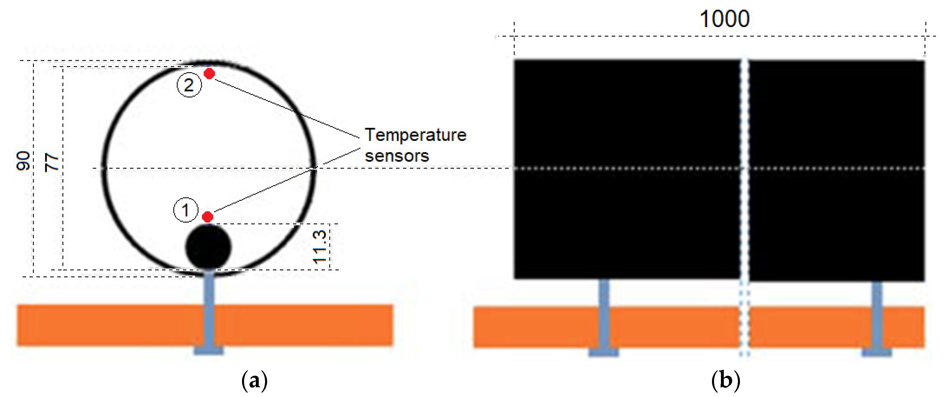
Figure 3 shows the position of the temperature sensors in each of the casing pipes. Two temperature sensors were placed in each of the four pipes, near the center of the length of the pipes. One of the sensors ➀ was placed directly on the cable and the other sensor ➁ was mounted on the opposite wall of the pipe.
Heat dissipation in the “cable-medium in the casing pipe-pipe wall” system caused temperature gradients, independently in each of the casing pipes. The NI PXI measurement platform was used for the acquisition, processing and recording of measurement data [
34]. The main devices of the measurement platform were:
NI PXIe-1082Q (National Instruments Chassis);
NI PXIe-8135 (Embedded Controller);
NI PXIe-6341 (Data Acquisition (DAQ) card with 16 single input channels, 16-bit, 0.5 MS/s);
NI SCB-68A (68-pin Connector Block with the input circuits for temperature sensors).
The software developed in the NI LabVIEW environment supervised the process of data acquisition and registration, and provided an initial analysis of the measurement results. This software was the key part of the temperature measurement channels as a part of the virtual instrument developed [
34]. Independent operations performed in the measurement system were the calibration of measurement channels, including the identification of the processing characteristics of the temperature sensors used (Negative Temperature Coefficient (NTC) thermistors) and the multi-channel temperature measurement operation. The advantage is that all of the calibration procedures can be initiated on demand within the available system operation options.
In order to make a preliminary assessment of the temperature distribution in the substances filling the casing pipes on the test stand, the following materials were used: bentonite dissolved in water in two different ratios (marked as b3—3% or b9—9% bentonite by weight to water) and CableCem mixed with water (marked as cc). As a part of the preliminary tests, several series of measurements of the thermal conductivity of these materials were carried out using the ISOMET 2114 Thermal Properties Analyzer [
35]. The thermal conductivity of the samples was tested within about a day from the preparation of the aqueous solutions of the fillers used.
3. Results and Discussion
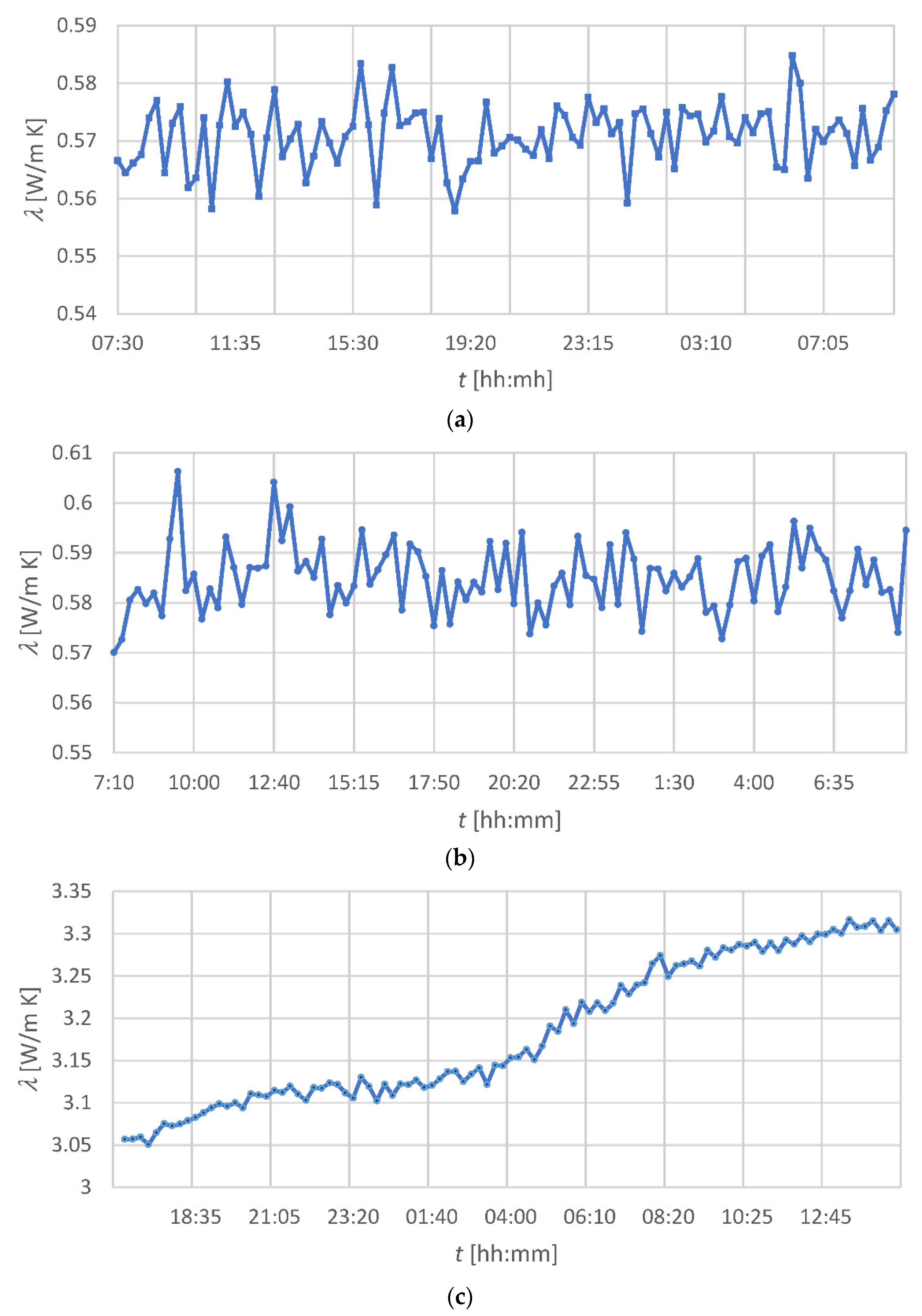
For the individual substances filling the casing pipes under investigation, the thermal conductivity measurement results are shown in
Figure 4.
The results in
Figure 4a,b show that the thermal conductivity of the bentonite-water mixtures is insignificantly dependent on the percentage of bentonite in the mixture and is stable from the formation of the mixture. It is worth mentioning that the preparation of a bentonite/water mixture with a bentonite content greater than 9% is very difficult. Due to the different compositions of bentonites from different sources, their thermal conductivity may differ. For example, in [
23] the thermal conductivity of bentonite was given as 0.75 W/(m∙K), while in [
36] this parameter ranged from about 0.3 to 0.8 W/(m∙K), depending on the water content in the mixture;
Figure 4c indicates that the thermal conductivity of the CableCem changes slightly after preparing the water mixture and stabilizes at approx. 3.3 W/(m∙K), which is a value higher than that declared in [
24]. For comparison, the thermal conductivity of the special thermally enhanced grouting artificial material used in the test described in [
13] was approximately 2.5 W/(m∙K). It should be noted that the value of parameter
λ is much more favorable for CableCem than the value of
λ characteristic for hydrated bentonite, and the value is beyond the level characteristic for soil conditions. Each of the casing pipes on the test stand was filled with a different medium. One of the pipes remained empty, i.e., filled with air. The second pipe was filled with a 3% mixture of bentonite and water (weight ratio). The third pipe was filled with a 9% bentonite/water mixture. Finally, the fourth pipe was filled with the CableCem/water mixture (1.5/1 by weight).
The basic measurements on the developed stand were carried out for various currents supplying the cable. They included the acquisition of the thermal responses recorded by sensors at individual points inside the casing pipes to a jump change in the current in the cable, and also after the current flow in the cable ceased. Additionally, the temperature of the cable led outside the pipes and the ambient temperature were measured, as well as the value of the current flowing through the cable.
Table A2 (in
Appendix A) contains a list of symbols, together with explanations, used in the following figures. The symbols concerning the sensors placed inside the casing pipes (the first eight symbols in
Table A2), with the initial index “c_”, denote the position ➀ of the sensor in
Figure 3, while those with the index “p_” refer to the position ➁ in
Figure 3. The temperature samples were taken every 1 minute.
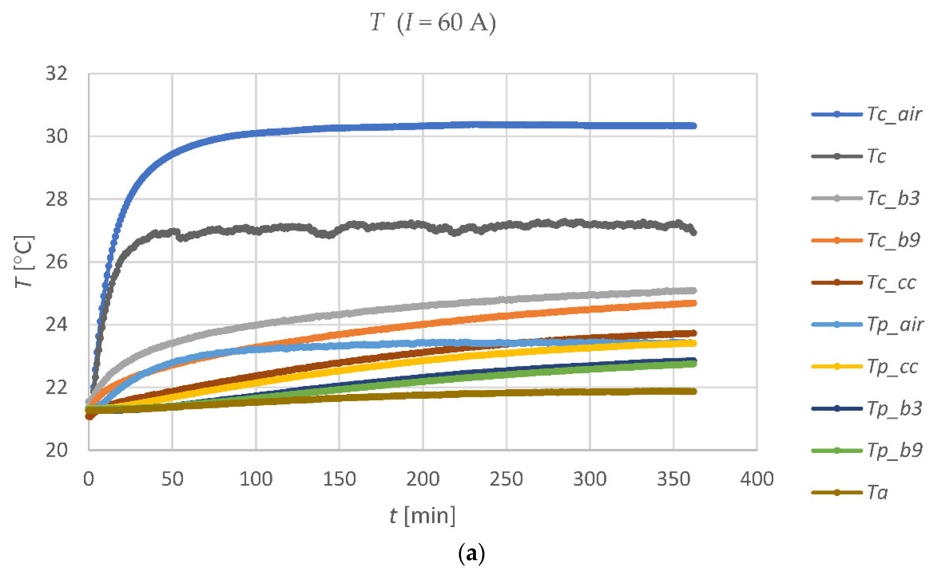
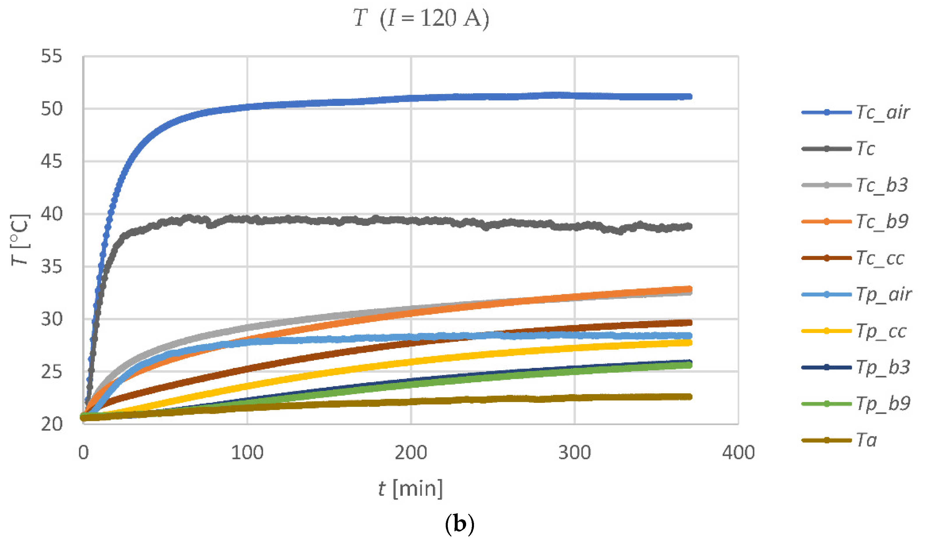
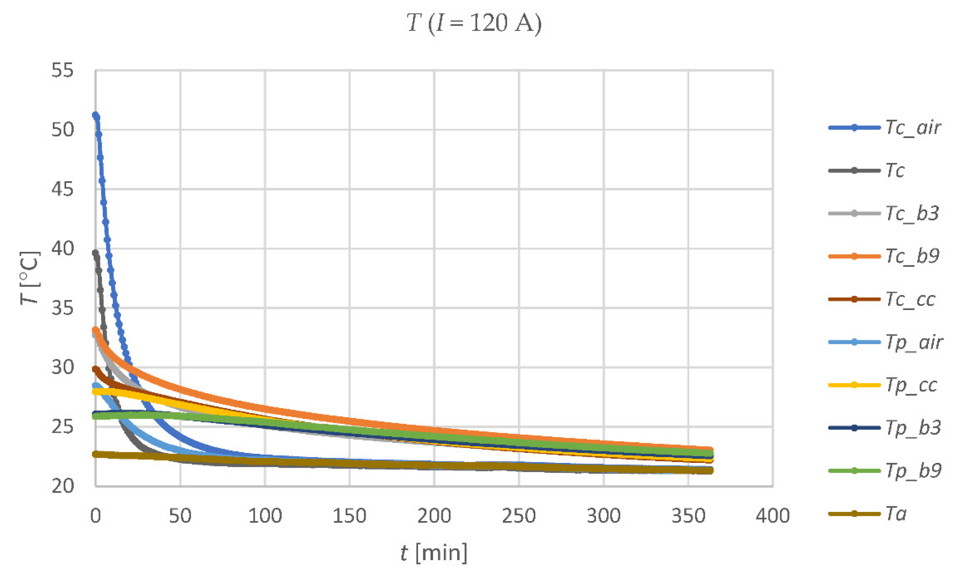
Figure 5 shows a graph of the temperature changes in the four casing pipes (on the cable and on the opposite inner surface of each pipe) with a current flowing through the cable of approx. 60 A and 120 A, respectively.
It can be easily noticed that the temperature
Tc_air of the cable in the air-filled casing pipe is significantly higher for both currents than the temperature
Tc of the cable in the open air, outside the pipes. In turn, the temperature
Tc_cc of the cable in a pipe filled with CableCem is the lowest temperature that the tested cable has on its individual parts. This proves that a lack of filling in the casing pipe section with a substance with the appropriate
λ coefficient causes a local increase in the cable temperature and creates a bottleneck in energy transmission. The significance of this phenomenon in relation to the filling of casing pipes is shown e.g., in [
29] or in [
32]. The properties of the medium surrounding the cable in a casing pipe are crucial for extensive submarine and underground power lines, where the cable is directly buried (in water or underground) and the casing pipes are used at the ends of the line. The cable ampacity limitations may appear mainly in these parts of the power line. They are caused by partial filling of the pipe or the low thermal conductivity of the filling medium. As an example of the cooling processes in the casing pipes on a test stand,
Figure 6 shows the temperature diagrams after turning off the 120 A current in the cable.
The thermal time constants of the individual media in the casing pipes strongly depend on the value of their thermal conductivity. A greater time constant means the possibility of increasing the instantaneous permissible current carrying capacity of the cable line. This is due to the lower temperature variation of the cable, caused by the change in the current in the cable, than the temperature variation that would occur in the overhead line. The time changes of the differences Δ
T between the temperatures indicated by the sensors placed in positions ➀ and ➁ (
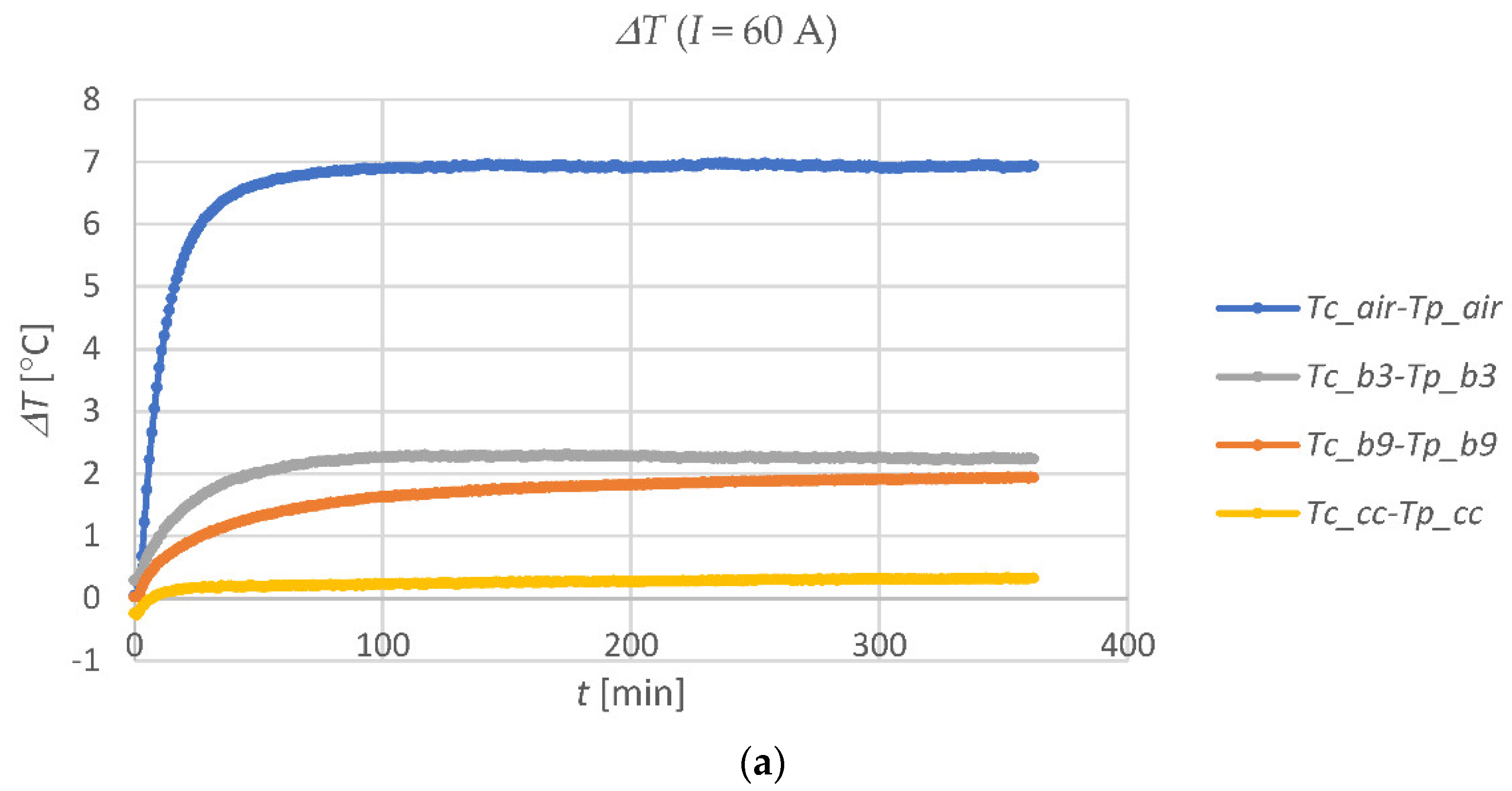
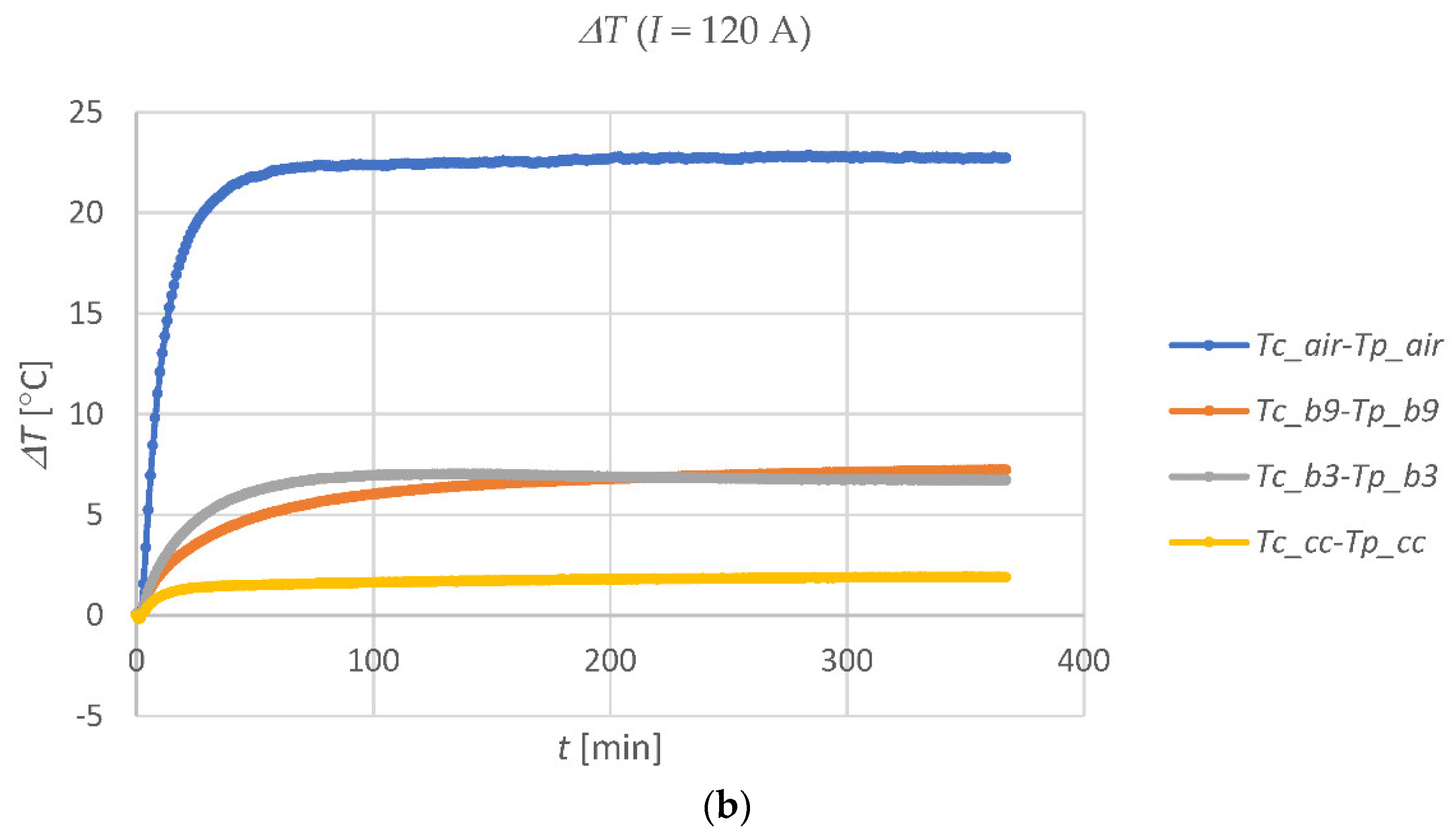
Figure 3) in each of the four casing pipes, after switching on the current in the cable, are shown in
Figure 7.
Figure 7a relates to 60 A, and
Figure 7b to 120 A.
The low temperature difference (
Tc_cc-Tp_cc) in the casing pipe with CableCem means that energy is efficiently dissipated from the cable, reducing its temperature. In contrast, the large temperature difference (
Tc_air-Tp_air) proves that the air in the casing pipe is a great barrier to energy dissipation.
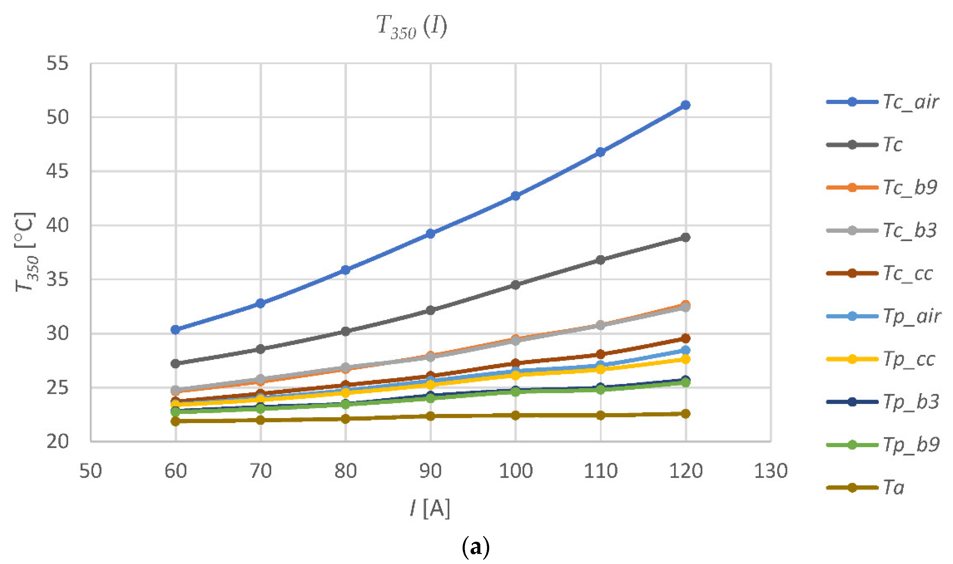
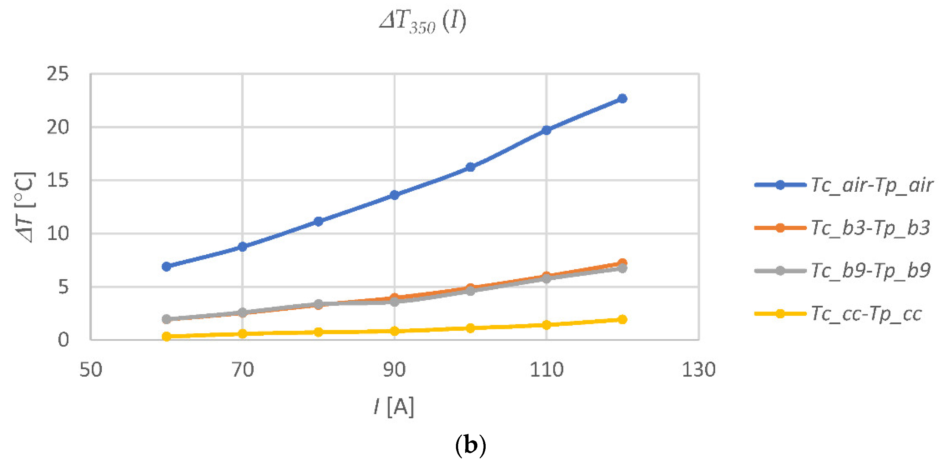
Figure 8 shows the temperature values at the considered points of the test stand, recorded for various currents at 350 minutes after switching on the current in the cable, and the corresponding temperature differences. At this point in time, all of the measured temperatures were close to the stabilized values.
Figure 8 shows that, as the current in the cable increases, the rate of temperature increases at all of the measuring points (except ambient temperature
Ta) (
Figure 8a), and the temperature differences (
Figure 8b) in the individual casing pipes increases as well, but the rate of change is different for the different conditions in the medium surrounding the cable. This conclusion is consistent with the results obtained, e.g., in [
14]. For example, for a current of 120 A in a cable, the temperature of the cable in the casing pipe filled with air is almost 15 °C higher than the temperature of the cable in the open air and more than 20 °C higher than the temperature of the cable in the pipe filled with CableCem. The cable in the pipe section filled with air reached 30 °C at a current of 60 A while the cable in the pipe with CableCem reached this temperature at 120 A (
Figure 8a). On the basis of the obtained results, it can be concluded that with a two-fold increase in the current in the cable, the difference in temperature Δ
T in the air pipe increased more than three times, while in the bentonite pipes, this increase is twofold, and for CableCem it changes one and a half times. The conclusions from these observations are consistent with the simulation results obtained, inter alia, in [
27].
The research results show that the introduction of substances with the desired thermomechanical properties filling the casing pipes, instead of filling them with cable bentonite, may contribute to increasing the efficiency of using underground cable channels in the distribution of electricity. CableCem is free from particles that can disrupt mechanical systems and is approved for heat conduction applications. A substance with such properties can be efficiently applied to the casing pipes by means of available pumps. With its use, much greater heat dissipation from the cable is obtained than when using the previously used fillers, and the conditions of its operation are stabilized. This allows an increase in the volume of electricity that can be transmitted in the cable line. The proven thermal properties of CableCem and the ability to conveniently dispense it into the casing pipe may be good reasons for choosing this material as a space filler in underground power cable lines. The measured value of CableCem’s thermal conductivity is approximately 3.3 W/(m∙K), which is more than five times higher than this parameter characterizing hydrated bentonites [
36].
For the different media surrounding the cable, the rates of temperature change with the change of current in the cable are different and they increase with the increase of current in the cable. The thermal time constants of individual media in the casing pipes strongly depend on the value of their thermal conductivity. A greater time constant means the possibility of increasing the instantaneous permissible current-carrying capacity of the cable line. The low temperature difference Δ
T in the casing pipe with CableCem means that energy is efficiently dissipated from the cable, reducing its temperature. In contrast, the large temperature difference Δ
T in the pipe filled with the air proves that the air in the casing pipe is a great barrier to energy dissipation. The values of the time constants related to the dynamics of temperature changes at the test stand were at a similar level as in [
14], and, at the same time, several times shorter than those shown in [
30], which results from the different properties of the substances used to surround the cable. An overhead line carrying the same current can be better cooled than an underground cable in a casing pipe filled with air.
The measurements were carried out in laboratory conditions with a set of casing pipes at the ambient temperature of the outside air. The remaining air in the casing pipe, i.e., the void space, as a bottleneck, limits strongly the energy dissipation from the cable to the outer environment. The temperature of the cable in the casing pipe with the air is always much higher than the temperature of the cable in the open air, and also higher than the temperature anywhere else on the test stand. This is proof of the importance of avoiding gaps inside the casing pipes. The results, shown in
Figure 5, prove how dangerous the existing air-filled spaces can be for underground cables, due to creating “bottlenecks” in the power lines. In order to avoid the overheating of the cable insulation, the permissible ampacity of the entire section of the line should be limited there.
As mentioned in the introduction, the available literature on heat dissipation from underground cables mainly includes articles containing valuable theoretical analyzes and simulation results [
15,
26,
27,
28,
29]. However, we selected several articles supported by the results of experimental research [
13,
14,
30,
31]. In some cases, they showed sophisticated and complex systems created to force heat generation in the cable [
13], or to simulate such a process with the use of special electric heaters [
30,
31]. The tests were carried out at different (variable or constant) levels of power released in the cable buried directly in the ground [
13,
14,
30,
31] or placed in a casing pipe [
13], and under various conditions of the experiment (e.g., the level of moisture or the type of material) related to the properties of the materials filling the cable’s surroundings. In some cases, the temperature measurements at different points of the medium surrounding the cable were made at different times [
14].
In the research system discussed in the paper, the temperatures and other values were recorded as a result of multi-point measurements carried out simultaneously for all of the sections of the underground power line model. A similar cable supply system was used in the tests shown in [
14], but without the possibility of smooth current control, with the cable directly buried in the sand and with a single-point temperature measurement. The configuration of the measurement system discussed in this article allows users to easily increase the number of temperature measurement points and to modify the set of the other measured quantities. For a temperature measurement with an accuracy below 0.4 °C, thermistors were used in the measuring system that enabled the calibration of each measuring channel. In other tests, e.g., those shown in [
13,
14,
30,
31], resistance temperature detectors (RTD) of Pt-100 type or thermocouples were usually used for temperature measurement, with a similar level of accuracy as in our measurements. At the same time, at our test stand, controlling and increasing the level of energy dissipated in the cable is an unlimited matter and only requires the use of additional, available power supplies. Due to the type of cable used in the tests, as well as the level of the current value adjusted in the tests to the cable used, the results presented in this article are more relevant for the LV cables than for the MV or HV cables. MV and HV cables have a much more complex structure, especially in the area of the insulating layer, and the value of the conducted current is usually much higher than in the tests carried out.


