Article

Investigation of Rotating Detonation Fueled by Liquid Kerosene

1
Science and Technology on Plasma Dynamics Laboratory, Air Force Engineering University, Xi’an 710038, China
2
Aeronautics Engineering College, Air Force Engineering University, Xi’an 710038, China
*
Author to whom correspondence should be addressed.
Energies 2022, 15(12), 4483; https://doi.org/10.3390/en15124483
Submission received: 5 May 2022 / Revised: 13 June 2022 / Accepted: 18 June 2022 / Published: 20 June 2022
(This article belongs to the Topic Fuel Combustion Chemistry)

Abstract

:
The performance of rotating detonation engines (RDEs) is theoretically better than that of traditional aero engines because of self-pressurization. A type of swirl injection scheme is introduced in this paper for two-phase detonation. On the one hand, experiments are performed on continuous rotating detonation of ternary “kerosene, hydrogen and oxygen-enriched air” mixture in an annular combustor. It is found that increasing the mass fraction of hydrogen can boost the wave speed and the stability of detonation waves’ propagation. One the other hand, characteristics of kerosene–hot air RDE is investigated for engineering application. Some unstable phenomena are recorded, such as changes of the number of detonation waves, low-frequency oscillations, and sporadic detonation.

1. Introduction

The rotating detonation engine (RDE) is a promising pressure gain device. In contrast to traditional engines adopting the Brayton cycle, it replaces isobaric combustion with detonation combustion, producing higher thermodynamic efficiency, less entropy, and faster rate of heat release. Moreover, the number of compressor stages can be reduced when integrated into turbine engines, thereby reducing the weight of the engines and improving the overall performance of the engines.
At present, research studies are mainly focused on gaseous fuels. Voitsckhovskii [1] obtained continuous detonation waves with premixed acetylene–oxygen for the first time. After that, Bykovskii and Frolov furthered investigated rotating detonation with various gaseous fuels such as hydrogen [2,3,4,5,6,7,8], acetylene [9,10,11,12], and methane [9]. Research contents included the influence of injection structures [2,8] and sizes of combustion chambers on RDE characteristics [2,4,7], wind tunnel experiments of ramjet-based detonation model under high Mach number incoming flow conditions [13], and performance evaluation of large-scale RDE [14]. The Air Force Research Laboratory, University of Cincinnati, and other American institutes mainly use hydrogen/air as propellants and have conducted a lot of fundamental research. Rankin observed the mixing of reactants and the propagation of detonation waves carefully with PLIF [15], OH chemiluminescence [16], and mid-infrared imaging [17]. Fotia studied the ignition characteristics [18] and the influence of the nozzle on the RDE performance [19,20]. Anand [21,22,23,24,25] classified the instability of RDE and revealed underlying mechanisms. Zhong [26] and Yang [27] studied the rotating detonation wave characteristics of various fuel mixtures.
Compared with liquid hydrocarbon fuels, gaseous fuels have lower energy density and are not easy to store; thus, they are not in accordance with engineering applications. Kerosene-based hydrocarbon fuel is a better choice for aviation. However, two-phase detonation is confronted with some problems, such as poor mixing of fuel and oxidizer and difficult initiation of low-activity mixtures. In order to overcome the two-phase initiation problem, institutions have tried many methods with the intention of enhancing the activity of reactants. For example, Bykovskii [3,28] successfully achieved kerosene–air rotating detonation with oxygen supplement and the addition of hydrogen or syngas. Kindracki [29] and Wolanski [30] found that both kerosene preheating and hydrogen addition can improve the initiation and operation stability of two-phase detonation. In addition, they studied the initiation process of kerosene–oxygen–nitrogen mixture in a short tube and drew the conclusion that a lower oxygen content requires greater initiation energy [31,32]. Falempin [33] used pre-evaporation to process liquid hydrocarbon fuels, greatly increasing the activity of reactants. Aiming at aviation kerosene alternative fuel n-decane, Song [34] and Xu [35] carried out a systematic research study on pre-combustion cracked characteristics of hydrocarbon fuel. Song [36,37,38] conducted pre-combustion cracking of kerosene and detected active components in cracked gas such as hydrogen, acetylene, and ethylene. Zhong [39,40] used pre-combustion cracked gas and oxygen-enriched air to investigate the effects of the flow rate and equivalence ratio, annular gap width, and combustion chamber width on the characteristics of detonation waves.
Many numerical simulations on two-phase RDE have been conducted. Zhang et al. [41,42,43] focused on n-heptane/air detonation in the two-dimensional domain with the Eulerian–Lagrangian method. They found that the droplet pre-vaporization and diameter have a dominating effect on detonation propagation speed. Hayashi et al. [44] used JP-10/air to obtain the effects of key parameters of droplets on two-phase rotating detonation wave propagation. Sun et al. [45] investigated the effects of total temperature of air on the characteristics of detonation waves and found that peak pressure of the detonation wave is negatively correlated with the total temperature of air.
Considering the combination of rotating detonation engine and aero-engines, we note that enhancing the activity of reactants by heating air is easier to implement than hydrogen addition, oxygen supplement, and kerosene cracking. However, there are few relevant results of kerosene–hot air RDE due to the limitations of experimental conditions. Two schemes increasing the activity of mixture are adopted in this paper for comparison: one is hydrogen addition (8.8–12.6% mass fraction) plus enriched-oxygen air (28.8–29.5% mass fraction), and the other is hot air (707~765 K). It is found that scheme of hot air is not as effective as the scheme of the hydrogen addition plus enriched oxygen.

2. Experimental Setup and Methodology

The experimental system can be divided into five parts, namely the fuel/oxidizer supply, rotating detonation chamber, ignition, data acquisition, and controlling system (Figure 1a).
The air supplied by a high-pressure air source has impurities removed through filters. By adjusting the reducing valve, the upstream pressure of the sonic orifice can be changed to control the mass flow rate of air. The heater connected with the air-supply pipe is fueled by hydrogen, heating air to simulate the temperature of inlet air of the rotating detonation combustion chamber. Oxygen is supplied to ensure the same oxygen content as air. The hydrogen and oxygen are both supplied from high-pressure gas cylinders, and the flow rate is controlled through sonic orifices. The fuel tank is connected to the high-pressure nitrogen cylinder, and the flow rate of kerosene can be controlled by adjusting the fuel tank’s pressure. A YK-LWGY-06 turbine flowmeter (range 15~150 g/s, max pressure 6.3 MPa, accuracy 1.0%) is used to monitor the flow rate of kerosene.
Critical dimensions of RDE are summarized in Table 1. As is shown in Figure 1b, kerosene flows into the combustor through 36 evenly distributed holes on the outer wall, with a diameter of 0.25 mm. The injection direction is at an angle of 60 degrees against the radial direction. The oxidizer is axially injected into the combustor through a slot of 3 mm in width. The pre-detonation tube fueled by hydrogen/oxygen is used for the ignition, and it has length of 500 mm and is placed 75 mm away from the outlet of the slot. The ignition device of the pre-detonation tube is a spark plug with ignition energy of 50 mJ. In order to weaken the ejection effect of the main air on the hydrogen–oxygen filling process of the pre-detonation tube, an aluminum film is placed at the outlet of the pre-detonation tube before each experiment, and this can significantly increase the initiation energy.
The sensor layout is shown in Figure 1c. A K-type thermocouple is placed in the air plenum to obtain the temperature of the hot air. Two LianNeng CY-YD-205H piezoelectric high-frequency pressure sensors are arranged at the end of the pre-detonation tube and the outer wall of the combustion chamber to monitor their operating status. Three steady-state pressure sensors are used to measure the steady-state pressures of the air plenum, fuel plenum, and combustion chamber, respectively. Pressure signals were recorded by the NI PXle-1071 data-acquisition system with a sampling frequency of 125 kHz.
The time sequence of the experiment is realized by setting the operation time of the solenoid valve and igniter, as shown in Figure 1d. Firstly, the main air is supplied, followed by hydrogen and oxygen supply and ignition of the heater to heat the incoming air. Kerosene is injected when the temperature of the air stabilizes. After a period of mixing, both hydrogen and oxygen are supplied into the pre-detonation tube. The pre-detonation tube is ignited upon filling. Moreover, the operating time of the rotating detonation is controlled by the kerosene supply time. The kerosene supply, hydrogen and oxygen supply of the heater, and main air are stopped in sequence when the experiment is over. The continuous operation time of the rotating detonation is about 1.5 s.
The water generated by hydrogen combustion exists in the hot flow in gaseous form when the heater operates. To keep the same oxygen content of actual air, more oxygen needs to be supplemented than that consumed by hydrogen combustion. The formulas for the hot air flow rate, oxygen mass fraction, and equivalent ratio are as follows:
m h o t   a i r = m a i r + m H 2 + m O 2
m O 2 % = 0.235 × m a i r + m O 2 8 × m H 2 m h o t   a i r
ϕ = m k e r o s e n e × 14.7 × 0.235 m h o t   a i r × m O 2 %
The mass flow rate of hot air includes the water vapor produced by the combustion of hydrogen. According to Equation (2), the oxygen mass fraction is obtained by adding the original oxygen content in the air plus the supplemental oxygen content and subtracting the oxygen content consumed by the hydrogen combustion and finally dividing by the total hot air flow rate. The equivalent ratio is defined by the ratio of theoretical mass flow rate of oxygen, which can be obtained by assuming complete combustion of kerosene, to the actual mass flow rate of oxygen.

3. Experimental Results and Analysis

3.1. Rotating Detonation Characteristics of Kerosene and Oxygen-Enriched Air with Hydrogen Addition

In our study, the mass flow rates of hydrogen and supplemental oxygen were 6 and 76 g/s, respectively. When the ignition of heater is removed, the fuel and oxidizer are kerosene–hydrogen and oxygen-enriched air, respectively. The operating conditions are summarized in Table 2.
In order to study the effect of the hydrogen mass fraction on the characteristics of detonation waves, Tests A6, A7, and A5 were selected for analysis. Their air mass flow rates are approximately the same with a monotonous decreases of mass fraction of hydrogen. Figure 2 shows the local high-frequency pressure diagrams of A6, A7, and A5 and the corresponding FFT results.
The dominant frequency of A6 is 1472 Hz, and the corresponding propagation velocity of the detonation wave is 924.9 m/s, thus indicating the single-wave mode. When the mass fraction of hydrogen drops from 12.3% to 10.2%, the frequency of detonation wave of A7 also drops to 1307 Hz, and the corresponding wave velocity is 819.3 m/s. The detonation wave still propagates in single-wave mode, but the wave velocity decreases by about 11.4%. When the hydrogen mass fraction is further reduced to 8.8%, it is found that the detonation wave of A5 becomes a dual-wave collision mode, with a dominant frequency of 2523 Hz and a wave speed of 792.6 m/s, which is about 14.3% lower than that of A6.
With the decrease of the mass fraction of hydrogen, the propagation speed of detonation wave continues to decrease because the chemical reaction activity of hydrogen is higher than that of kerosene. This is consistent with Bykovskii’s results [28]. The decrease of the mass fraction of hydrogen will reduce the activity of reactants, thereby decreasing the velocity of the detonation wave. The dual-wave collision mode appears in operating A5 mainly because the mass flow of kerosene is significantly higher than operating A6 and A7, namely the higher pressure before injection. It helps to increase the injection momentum flux ratio and thus makes kerosene fully penetrate the air flow. As the penetration depth increases, the mixing of the reactant before the detonation wave becomes better, increasing the pressure of the detonation wave. Because the air mass flow rate remains nearly constant, the velocity of air injection will decrease, resulting in a decrease in the height of the wavefront mixture, thus making the detonation wave change from a single-wave mode to a dual-wave collision mode.
In order to study the influence of the air mass flow rate on the characteristics of detonation waves, A1, A2, A4, A6, and A10 were selected. The hydrogen mass fraction is about 12%. Mass flow rates increase successively, and the equivalent ratio decreases successively; Figure 3 shows the variation of the detonation wave propagation velocity with the air mass flow rate.
For cases of 12% hydrogen mass fraction, the propagation speed of the detonation wave gradually decreases as the air mass flow rate climbs. It can be explained by Bohon’s results in which poor mixing is related to low injection momentum flux ratios [46]. When the air flow rate increases, the injection momentum flux ratio decrease, and this effectively reduces the penetration depth of the fuel. The mixing effect of the wavefront mixture becomes worse, thereby reducing the detonation wave velocity.

3.2. Experimental Research on Rotating Detonation of Liquid Kerosene/Hot Air
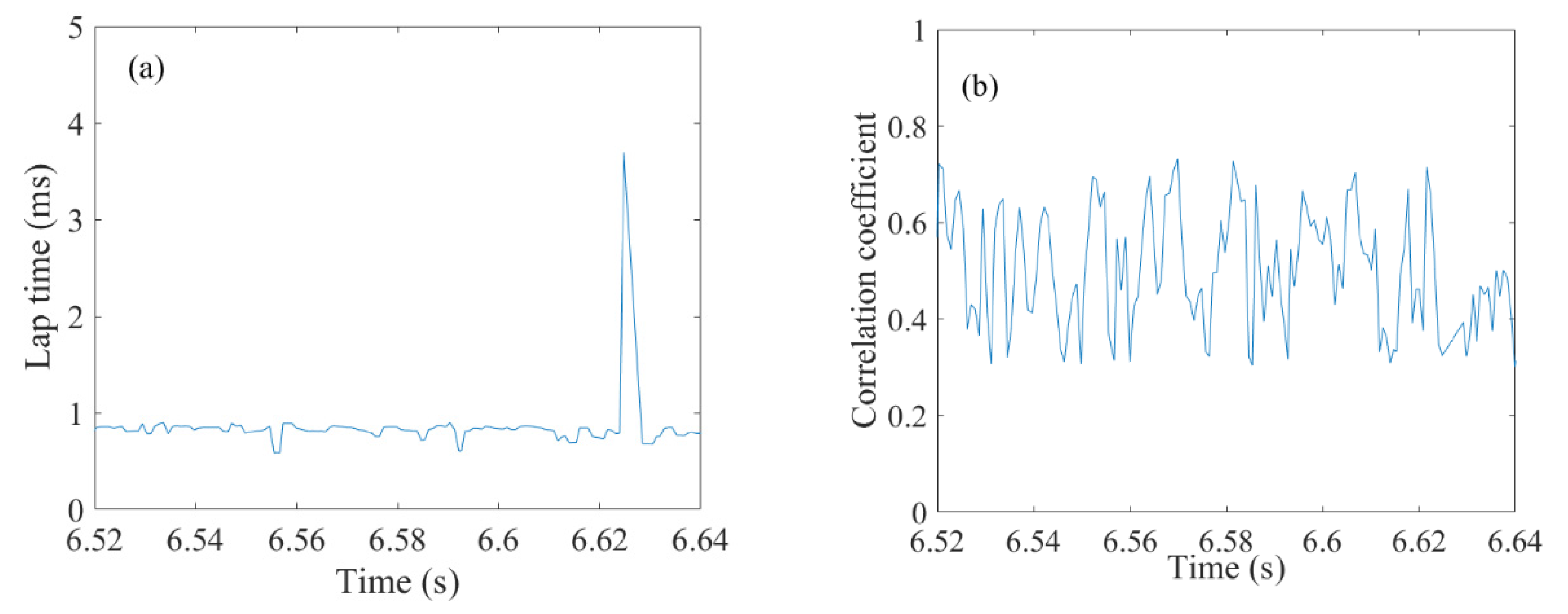
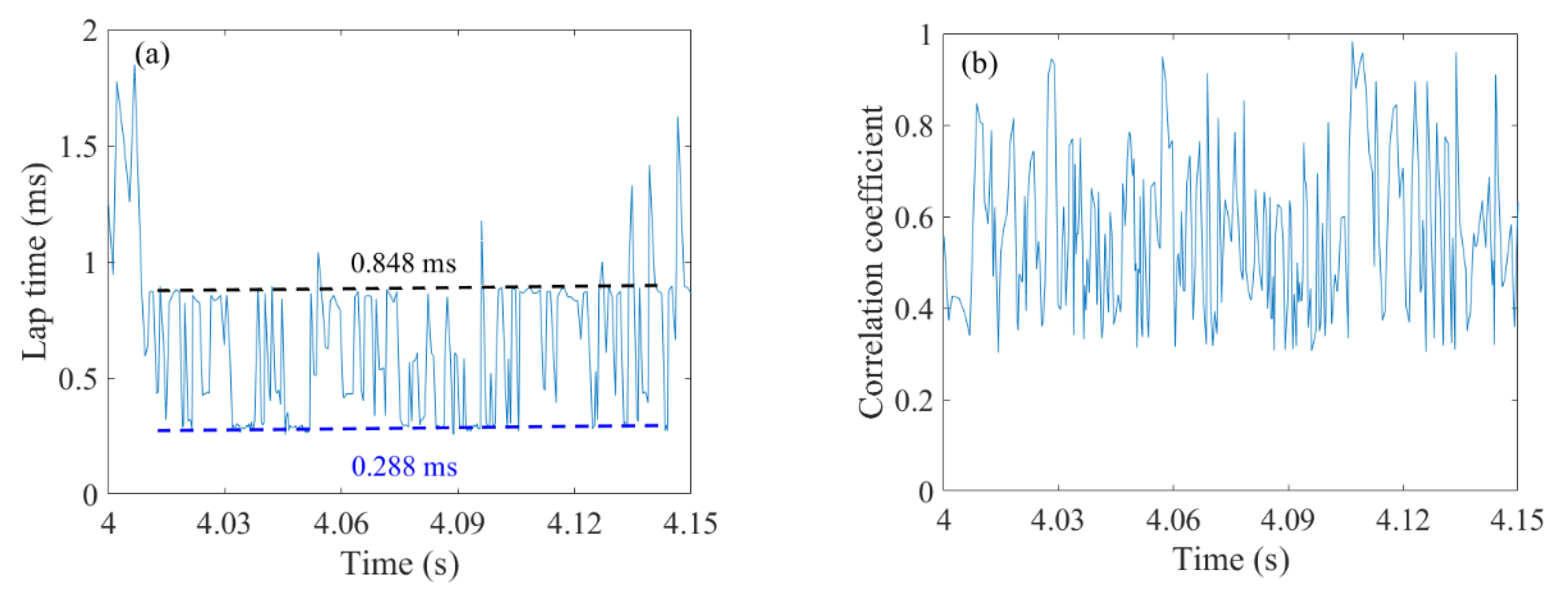
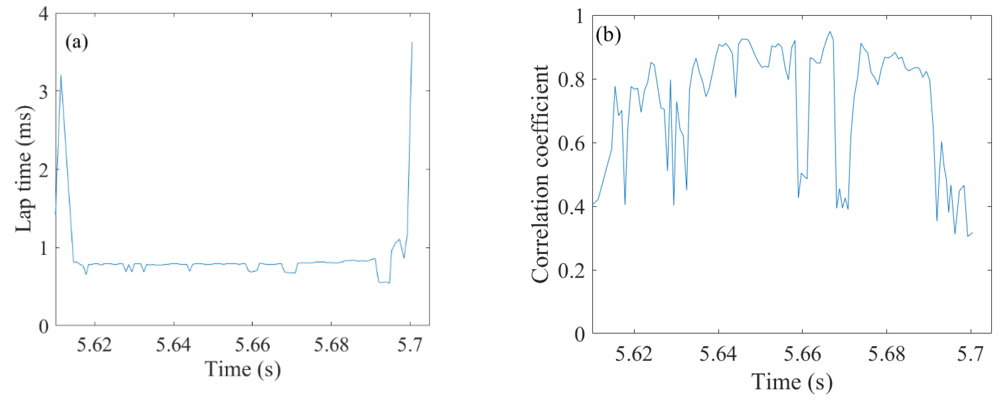
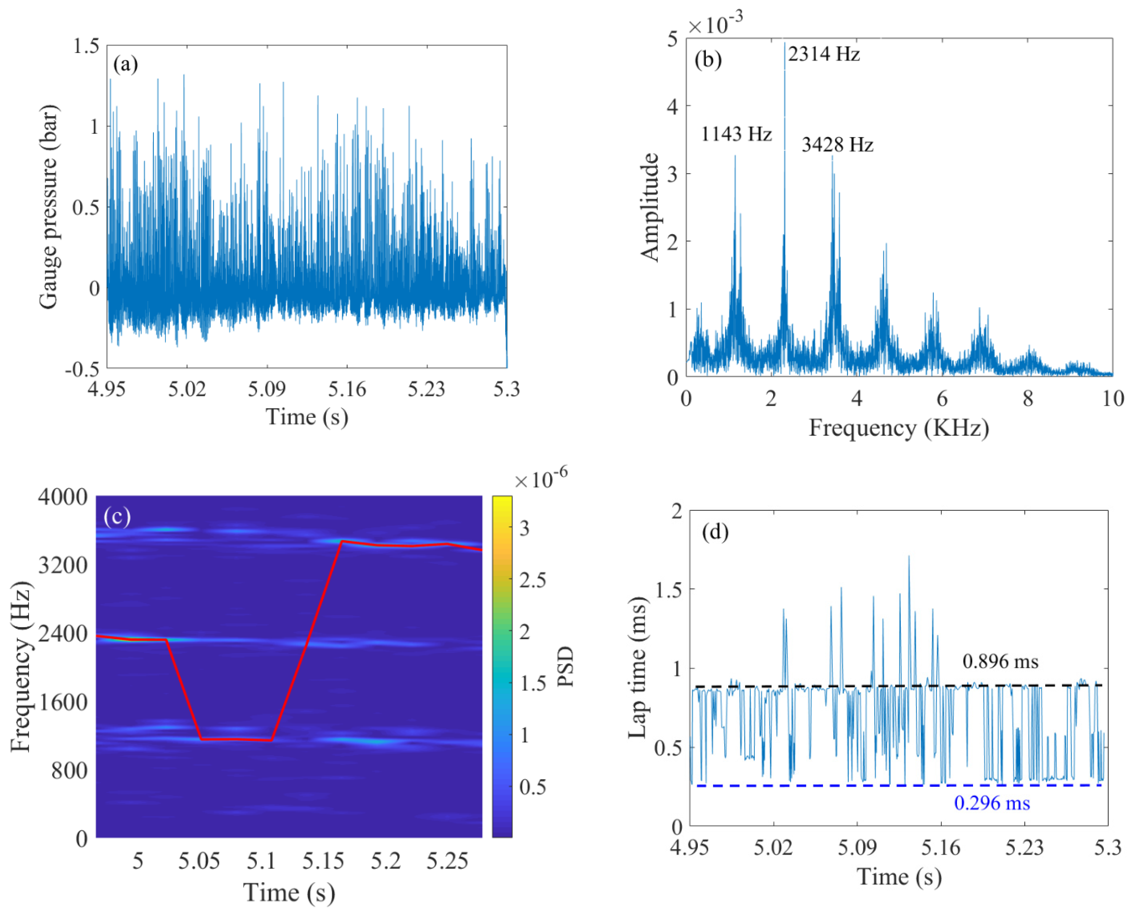
The calculated oxygen mass fraction in the experiment is about 24.4%, which is slightly higher than the oxygen mass fraction in air (23.5%). The temperature range of the inlet flow is 707~765 K. All operating conditions of liquid kerosene/hot air are summarized in Table 3. Three combustion modes are observed in the experiments. They are ignition failure, deflagration, and unstable detonation, respectively. Unfortunately, no continuous rotating detonation waves were observed in the experiment, even when the air temperature reached 765 K. It is speculated to be related to key geometric parameters, such as combustor widths.
Figure 4a shows pressure curves for the combustion chamber, pre-detonation tube, kerosene plenum, and air plenum under B4. The pressure in the kerosene plenum decreased slightly during the experiment, approximately to 2.1 MPa, while the pressure in the air plenum was about 0.54 MPa. Because of the high-temperature testing environment, the high-frequency pressure sensor experiences temperature drift. By analyzing the high-frequency pressure signal of the combustion chamber, it is found that multiple extinction events occur within the time period of 5–6 s, in which signal is relatively messy. A stable detonation wave signal appears between 6.5 and 6.66 s during the ending stage.
High-pass filtering is performed on the high-frequency pressure signal of the combustion chamber in the period of 6.5–6.66 s, as shown in Figure 4b. The main frequency and time–frequency information of the detonation wave are shown in Figure 4c,d, respectively. It can be seen from Figure 4c that the dominant frequency of the detonation wave is 1162 Hz, corresponding to the propagation speed of 1000 m/s, which is a typical single-wave mode. Figure 4d shows the variation of the detonation wave frequency with time. It can be seen that the detonation-wave propagation frequency is relatively stable, fluctuating at around 1136 Hz, which is close to the FFT result. Although FFT can quickly analyze the frequency components of high-frequency pressure signals, it cannot show the variation of the detonation wave’s frequency with time. As for STFT, it does reflect the time–frequency changes clearly, but it fails to guarantee that the time resolution and frequency resolution reach the optimal at the same time. Gutmark [47] used the autocorrelation method to analyze the pressure signal of single high-frequency sensor, as it can identify information such as the lap time and extinction events of detonation waves with high accuracy. Therefore, the autocorrelation analysis method is introduced to supplement the FFT and STFT results.
The autocorrelation analysis method is used to analyze the high-frequency pressure signal of the combustion chamber in the 6.5~6.66 s of B4. The change of lap times and the maximal values of autocorrelation coefficient with time are shown in Figure 5a,b, respectively. In the detonation-wave lap-times diagram, a spike appears at 6.625 s, and the corresponding autocorrelation coefficient is also reduced, indicating the occurrence of detonation-wave extinction event. The average lap time, except the peak, is 0.8101 ms, corresponding to the propagation speed of 775.2 m/s, which is slightly higher than the result from the spectrum analysis. The autocorrelation coefficient is in a range from 0.3 to 0.7. According to the correlation strength of Table 4, the detonation wave is moderately correlated.

3.3. Instability

A variety of detonation-wave instability phenomena were discovered during the experiment, including changes of the detonation wave number, low-frequency oscillation, and sporadic detonation.
As shown in Figure 6a, the lap time of the detonation wave alternately changes between 0.848 and 0.288 ms within 4~4.16 s, corresponding to the propagation speeds of 740.9 and 2181.7 m/s, respectively. Compared with the theoretical C-J wave velocity, the detonation wave with a lap time of 0.288 ms corresponds to a propagation velocity of 727.2 m/s, which is a co-rotating three-wave mode. The variation range of the correlation coefficient is 0.3~1.0 (Figure 6b), indicating that the detonation wave has high instability. Since the wave speeds of two modes are close and the probability of co-rotating three-wave modes is low, the delay of 0.288 ms may be caused by the triple main frequency component.
The analysis of the pressure signal in the period of 5.61~5.71 s was performed, and the lap time and correlation coefficient curves with time were obtained, as shown in Figure 7a,b. The lap time of the detonation wave is 0.7859 ms, and the corresponding wave velocity is 799.1 m/s, which is a single-wave mode. The fluctuation range of the correlation coefficient is 0.4~1.0, which indicates that the stability of the detonation wave increases compared with the time period of 4~4.16 s.
For B14 (flow rate of 1023 g/s, equivalent ratio of 1.03, and heating temperature of 713 K), the high-frequency pressure signal of the combustion chamber and the corresponding FFT, STFT, and autocorrelation analysis results between 4.95 and 5.3 s are shown in Figure 8. It can be seen from the FFT results that, frequency, components at 1143, 2314, and 3428 Hz have larger amplitudes. The time–frequency diagram can reflect the change of the main frequency more clearly. For example, the main frequency remains 2316 Hz from 4.95 s to 5.023 s, and then it drops to 1152 Hz at 5.051 s, followed by a long period stabilization at 3420 Hz after 5.108 s. From the results of the autocorrelation, the detonation wave lap time fluctuates among three values of 0.296, 0.416, and 0.896 ms. Three signal analysis methods using FFT, STFT, and autocorrelation show a high degree of consistency. Unfortunately, the detonation wave mode cannot be accurately identified because only one high-frequency pressure sensor is used to record detonation waves. For example, in the time–frequency diagram from 4.95 to 5.023 s, the dominant frequency of 2316 Hz corresponds to a propagation speed of 1455 m/s. At this time, it cannot be determined whether the mode is double-wave collision or co-rotating two-wave. Considering that the co-rotating double-wave requires a higher filling height of fresh mixture, the possibility of a two-wave collision mode is greater. For the time–frequency diagram from 5.05 to 5.1 s, the dominant frequency of 1152 Hz corresponds to a propagation speed of 718.2 m/s, which is a single-wave mode. At the same time, the time-lag diagram is stable at 0.896 ms at this stage, and the corresponding wave velocity is 701.2 m/s.
Test B13 shows another kind of instability. It can be clearly observed that the pressure peak of the detonation wave presents periodic oscillation characteristics, as shown in Figure 9a. It can be explained by the self-adjusting mechanism discussed by Liu [48]. This phenomenon is related to the interaction between the detonation wave and the air plenum. When the detonation wave is strong, the peak pressure is high enough to slow down the filling process, resulting in insufficient height of the fresh mixture formed in the front of the detonation wave. After detonation combustion, heat released by it is not enough to maintain the intensity of the original detonation wave, making the detonation wave weaker. To be continued, the peak pressure of the weak detonation wave is lower, and this speeds up the filling process, so that more fresh mixture is formed in front of the detonation wave, and the intensity of the detonation wave increases after gaining more energy. The above process repeats itself, resulting in periodic changes in the peak pressure of the detonation wave.
For the selected time period of test B4, the detonation wave did not realize continuous self-sustained propagation. However, a detonation wave signal does appear at some moments, while the other moments are deflagration, which is a typical sporadic detonation, as shown in Figure 9b. This is because the pressure between the detonation wave and air plenum has not reached a balanced state. Therefore, the critical height of the fresh mixture cannot be reached before the detonation wave, meaning that the self-sustaining condition of the detonation wave is not satisfied. Therefore, the detonation wave can only propagate a few laps at a certain moment. Then it is immediately decoupled to form a deflagration.

3.4. Operation Boundary of Liquid Kerosene/Hot Air Rotating Detonation

The relationship between modes’ distribution with equivalent ratios and temperatures are summarized in Figure 10. Three states were found in the experiment, namely ignition failure, deflagration, and unstable detonation. When the equivalence ratio is less than 0.55, either no flame is observed at the exit of the annular combustion chamber or the flame duration is very short, indicating that the activity of the mixture is so insufficient in that case that it cannot be ignited. The main reason for this phenomenon is that the pressure before kerosene injection is low, resulting in poor atomization and the inability to reach the combustion conditions. As the equivalence ratio increases, the effect of kerosene atomization is improved, and the low-frequency deflagration mode gradually appears. However, due to the low equivalent ratio and insufficient combustion heat release, the shock wave cannot obtain sufficient energy and degenerate into a weak compression wave, thus causing the compression of the fresh mixture to weaken and further reducing the combustion rate. Finally, the combustion wave and shock wave decouple. Increasing the incoming air temperature under low-equivalence-ratio conditions can change the mode from deflagration to unstable detonation. The increase in temperature has two favorable factors: it can accelerate the evaporation of kerosene and make the fresh mixture more uniform and increase the activity of the fresh mixture, thus enhancing the chemical reaction rate and realizing detonation combustion. When the equivalence ratio is higher than 0.7, many kinds of unstable detonation appear in sequence. Unfortunately, no stable detonation modes are observed in the experiment. It can be attributed to two reasons. On the one hand, a high air temperature can decrease the intensity of detonation waves. Figure 11 summarizes the effects of air temperature on critical parameters of detonation waves calculated by CEA. It can be observed that the high temperatures of reactants are detrimental to the intensity of the detonation wave. On the other hand, the combustion chamber’s width does not match detonation wave cell size well. According to Wang’s investigation, combustor widths have great influence on propagation modes of detonation waves [49]. The stability of detonation waves can be reduced when combustor widths decrease. Therefore, the combustor width needs to be increased to maintain the steady propagation of the detonation wave.

4. Conclusions

In this paper, the rotating detonation wave characteristics of liquid kerosene/oxygen-enriched air under the condition of adding hydrogen and liquid kerosene/hot air were studied, respectively. A type of swirl injection scheme was adopted. Kerosene was injected through a series of small holes that is 60 degrees against the radial direction. The main conclusions are as follows:
(1)
Under approximately the same air mass flow conditions, the higher the mass fraction of hydrogen is in the fuel, the greater the propagation speed of the detonation wave can be. As the mass flow of kerosene increases, the detonation wave gradually changes from single-wave mode to dual-wave collision mode;
(2)
For a low equivalence ratio, increasing the air flow will reduce the injection momentum flux ratio, making the mixing effect of the wavefront mixture worse and the wave speed lower.
(3)
A variety of detonation wave instabilities were discovered during the experiment, including changes in the number of detonation waves, low-frequency oscillations, and sporadic detonation.
(4)
Due to a high air temperature and mismatch of combustor width and detonation cell size, a stable detonation mode was not obtained in all the liquid kerosene/hot air rotating detonation operation conditions.
In view of the fact that the hot air within the temperature range studied in this paper does not achieve full detonation, it is still necessary to explore new and applicable auxiliary methods to promote the engineering application of rotating detonation engines fueled by kerosene.

Author Contributions

Conceptualization, J.Z. and Y.Z.; Data curation, F.S.; Formal analysis, J.Z.; Methodology, X.Y.; Resources, Y.Z.; Software, S.X.; Validation, X.Y.; Visualization, S.X.; Writing—original draft, J.Z.; Writing—review & editing, F.S. All authors have read and agreed to the published version of the manuscript.

Funding

This research was funded by National Natural Science Foundation of China, grant number 52106190.

Institutional Review Board Statement

Not applicable.

Informed Consent Statement

Not applicable.

Data Availability Statement

Not applicable.

Conflicts of Interest

The authors declare no conflict of interest.

References

  1. Voitsekhovskii, B.V. Maintained detonations. Doklady Akademii Nauk UzSSSr 1959, 129, 1254–1256. [Google Scholar]
  2. Bykovskii, F.A.; Zhdan, S.A.; Vedernikov, E.F. Continuous spin detonation in annular combustors. Combust. Explos. Shock. Waves 2005, 41, 449–459. [Google Scholar] [CrossRef]
  3. Bykovskii, F.A.; Zhdan, S.A.; Vedernikov, E.F. Continuous spin detonation of fuel-air mixtures. Combust. Explos. Shock. Waves 2006, 42, 463–471. [Google Scholar] [CrossRef]
  4. Bykovskii, F.A.; Zhdan, S.A.; Vedernikov, E.F. Continuous spin detonation of hydrogen-oxygen mixtures. 1. Annular cylindrical combustors. Combust. Explos. Shock. Waves 2008, 44, 150–162. [Google Scholar] [CrossRef]
  5. Bykovskii, F.A.; Zhdan, S.A.; Vedernikov, E.F. Continuous spin detonation of hydrogen-oxygen mixtures. 2. Combustor with an expanding annular channel. Combust. Explos. Shock. Waves 2008, 44, 330–342. [Google Scholar] [CrossRef]
  6. Bykovskii, F.A.; Vedernikov, E.F. Continuous spin detonation of hydrogen-oxygen mixtures. 3. Methods of measuring flow parameters and flow structure in combustors of different geometries. Combust. Explos. Shock. Waves 2008, 44, 451–460. [Google Scholar] [CrossRef]
  7. Bykovskii, F.A.; Zhdan, S.A.; Vedernikov, E.F. Realization and modeling of continuous spin detonation of a hydrogen-oxygen mixture in flow-type combustors. 1. Combustors of cylindrical annular geometry. Combust. Explos. Shock. Waves 2009, 45, 606–617. [Google Scholar] [CrossRef]
  8. Bykovskii, F.A.; Zhdan, S.A.; Vedernikov, E.F. Realization and modeling of continuous spin detonation of a hydrogen-oxygen mixture in flow-type combustors. 2. Combustors with expansion of the annular channel. Combust. Explos. Shock. Waves 2009, 45, 716. [Google Scholar] [CrossRef]
  9. Bykovskii, F.A.; Mitrofanov, V.V. Detonation combustion of a gas mixture in a cylindrical chamber. Combust. Explos. Shock. Waves 1980, 16, 570–578. [Google Scholar] [CrossRef]
  10. Bykovskii, F.A.; Vasil’ev, A.A.; Vedernikov, E.F.; Mitrofanov, V.V. Explosive combustion of a gas mixture in radial annular chambers. Combust. Explos. Shock. Waves 1994, 30, 510–516. [Google Scholar] [CrossRef]
  11. Bykovskii, F.A.; Mitrofanov, V.V.; Vedernikov, E.F. Continuous detonation combustion of fuel-air mixtures. Combust. Explos. Shock. Waves 1997, 33, 344–353. [Google Scholar] [CrossRef]
  12. Bykovskii, F.A.; Vedernikov, E.F. Continuous detonation of a subsonic flow of a propellant. Combust. Explos. Shock. Waves 2003, 39, 323–334. [Google Scholar] [CrossRef]
  13. Frolov, S.M.; Zvegintsev, V.I.; Ivanov, V.S.; Aksenov, V.S.; Shamshin, I.O.; Vnuchkov, D.A.; Nalivaichenko, D.G.; Berlin, A.A.; Fomin, V.M. Wind tunnel tests of a hydrogen-fueled detonation ramjet model at approach air stream Mach numbers from 4 to 8. Int. J. Hydrogen Energy 2017, 42, 25401–25413. [Google Scholar] [CrossRef]
  14. Frolov, S.M.; Aksenov, V.S.; Ivanov, V.S.; Shamshin, I.O. Large-scale hydrogen–air continuous detonation combustor. Int. J. Hydrogen Energy 2015, 40, 1616–1623. [Google Scholar] [CrossRef]
  15. Rankin, B.A.; Fugger, C.A.; Richardson, D.R.; Cho, K.Y.; Hoke, J.; Caswell, A.W.; Gord, J.R.; Schauer, F. Evaluation of Mixing Processes in a Non-Premixed Rotating Detonation Engine Using Acetone PLIF. In Proceedings of the AIAA Aerospace Sciences Meeting, San Diego, CA, USA, 4–8 January 2016. [Google Scholar]
  16. Rankin, B.A.; Richardson, D.R.; Caswell, A.W.; Naples, A.; Hoke, J.; Schauer, F. Imaging of OH* Chemiluminescence in an Optically Accessible Nonpremixed Rotating Detonation Engine. In Proceedings of the 53rd AIAA Aerospace Sciences Meeting, Kissimmee, FL, USA, 5–9 January 2015. [Google Scholar]
  17. Rankin, B.A.; Codoni, J.R.; Cho, K.Y.; Hoke, J.; Schauer, F.R. Mid-infrared imaging of an optically accessible non-premixed hydrogen-air rotating detonation engine. In Proceedings of the 55th AIAA Aerospace Sciences Meeting, Grapevine, TX, USA, 9–13 January 2017; p. 0370. [Google Scholar]
  18. Fotia, M.; Hoke, J.; Schauer, F. Experimental Ignition Characteristics of a Rotating Detonation Engine under Backpressured Conditions. In Proceedings of the AIAA Aerospace Sciences Meeting, Kissimmee, FL, USA, 5–9 January 2013. [Google Scholar]
  19. Fotia, M.; Schauer, F.; Hoke, J. Experimental testing of a rotating detonation engine coupled to nozzles at conditions approaching flight. In Proceedings of the 25th International Colloquium on the Dynamics of Explosions and Reactive Systems, Leeds, UK, 7 August 2015; p. 15. [Google Scholar]
  20. Fotia, M.; Kaemming, T.A.; Codoni, J.R.; Hoke, J.; Schauer, F. Experimental thrust sensitivity of a rotating detonation engine to various aerospike plug-nozzle consfigurations. In Proceedings of the AIAA Scitech 2019 Forum, San Diego, CA, USA, 7–11 January 2019; p. 1743. [Google Scholar]
  21. Anand, V.; George, A.S.; Driscoll, R.; Gutmark, E. Characterization of instabilities in a rotating detonation combustor. Int. J. Hydrogen Energy 2015, 40, 16649–16659. [Google Scholar] [CrossRef]
  22. Anand, V.; George, A.S.; Driscoll, R.; Gutmark, E. Longitudinal pulsed detonation instability in a rotating detonation combustor. Exp. Therm. Fluid Sci. 2016, 77, 212–225. [Google Scholar] [CrossRef]
  23. Anand, V.; George, A.S.; Gutmark, E. Amplitude modulated instability in reactants plenum of a rotating detonation combustor. Int. J. Hydrogen Energy 2017, 42, 12629–12644. [Google Scholar] [CrossRef]
  24. Anand, V.; Gutmark, E. Types of Low Frequency Instabilities in Rotating Detonation Combustors. In Active Flow and Combustion Control 2018; Springer: Cham, Switzerland, 2019; pp. 197–213. [Google Scholar]
  25. Anand, V.; George, A.S.; de Luzan, C.F.; Gutmark, E. Rotating detonation wave mechanics through ethylene-air mixtures in hollow combustors, and implications to high frequency combustion instabilities. Exp. Therm. Fluid Sci. 2018, 92, 314–325. [Google Scholar] [CrossRef]
  26. Zhong, Y.; Jin, D.; Wu, Y.; Chen, X. Investigation of rotating detonation wave fueled by “ethylene-acetylene-hydrogen” mixture. Int. J. Hydrogen Energy 2018, 43, 14787–14797. [Google Scholar] [CrossRef]
  27. Yang, X.; Song, F.; Wu, Y.; Zhong, Y.; Xu, S. Investigation of rotating detonation fueled by a methane–hydrogen–carbon dioxide mixture under lean fuel conditions. Int. J. Hydrogen Energy 2020, 45, 21995–22007. [Google Scholar] [CrossRef]
  28. Bykovskii, F.A.; Zhdan, S.A.; Vedernikov, E.F. Continuous Detonation of the Liquid Kerosene–Air Mixture with Addition of Hydrogen or Syngas. Combust. Explos. Shock. Waves 2019, 55, 589–598. [Google Scholar] [CrossRef]
  29. Kindracki, J. Experimental research on rotating detonation in liquid fuel–gaseous air mixtures. Aerosp. Sci. Technol. 2015, 43, 445–453. [Google Scholar] [CrossRef]
  30. Wolanski, P. Application of the Continuous Rotating Detonation to Gas Turbine. Appl. Mech. Mater. 2015, 782, 3–12. [Google Scholar] [CrossRef]
  31. Kindracki, J. Analysis of the experimental results of the initiation of detonation in short tubes with kerosene–oxidizer mixtures. J. Loss Prev. Process Ind. 2013, 26, 1515–1523. [Google Scholar] [CrossRef]
  32. Kindracki, J. Study of detonation initiation in kerosene–oxidizer mixtures in short tubes. Shock Waves 2014, 24, 603–618. [Google Scholar] [CrossRef] [Green Version]
  33. Le Naour, B.; Falempin, F.H.; Coulon, K. MBDA R&T effort regarding continuous detonation wave engine for propulsion-status in 2016. In Proceedings of the 21st AIAA International Space Planes and Hypersonics Technologies Conference, Xiamen, China, 6–9 March 2017; p. 2325. [Google Scholar]
  34. Song, F.; Wu, Y.; Xu, S.; Jin, D.; Jia, M. N-decane decomposition by microsecond pulsed DBD plasma in a flow reactor. Int. J. Hydrogen Energy 2019, 44, 3569–3579. [Google Scholar] [CrossRef]
  35. Xu, S.; Jin, D.; Song, F.; Wu, Y. Experimental investigation on n-decane plasma cracking in an atmospheric-pressure argon environment. Plasma Sci. Technol. 2019, 21, 085503. [Google Scholar] [CrossRef]
  36. Song, F.; Wu, Y.; Xu, S.; Jin, D.; Chen, X. Pre-combustion cracking characteristics of kerosene. Chem. Phys. Lett. 2019, 737, 136812. [Google Scholar] [CrossRef]
  37. Song, F.; Wu, Y.; Xu, S.; Yang, X.; Chen, X. The impact of fuel ratio and refueling mode on pre-combustion cracking properties of RP-3 kerosene. Int. J. Hydrogen Energy 2020, 45, 28505–28519. [Google Scholar] [CrossRef]
  38. Song, F.; Wu, Y.; Xu, S.; Yang, X.; Chen, X. Effects of refueling position and residence time on pre-combustion cracking characteristic of aviation kerosene RP-3. Fuel 2020, 270, 117548. [Google Scholar] [CrossRef]
  39. Zhong, Y.; Wu, Y.; Jin, D.; Chen, X.; Yang, X.; Wang, S. Investigation of rotating detonation fueled by the pre-combustion cracked kerosene. Aerosp. Sci. Technol. 2019, 95, 105480. [Google Scholar] [CrossRef]
  40. Zhong, Y.; Wu, Y.; Jin, D.; Chen, X.; Yang, X.; Wang, S. Effect of channel and oxidizer injection slot width on the rotating detonation fueled by pre-combustion cracked kerosene. Acta Astronaut. 2019, 165, 365–372. [Google Scholar] [CrossRef]
  41. Meng, Q.; Zhao, M.; Zheng, H.; Zhang, H. Eulerian-Lagrangian modelling of rotating detonative combustion in partially pre-vaporized n-heptane sprays with hydrogen addition. Fuel 2021, 290, 119808. [Google Scholar] [CrossRef]
  42. Meng, Q.; Zhao, N.; Zhang, H. On the distributions of fuel droplets and in situ vapor in rotating detonation combustion with prevaporized n-heptane sprays. Phys. Fluids 2021, 33, 043307. [Google Scholar] [CrossRef]
  43. Zhao, M.; Zhang, H. Rotating detonative combustion in partially pre-vaporized dilute n-heptane sprays: Droplet size and equivalence ratio effects. Fuel 2021, 304, 121481. [Google Scholar] [CrossRef]
  44. Hayashi, A.K.; Tsuboi, N.; Dzieminska, E. Numerical study on JP-10/air detonation and rotating detonation engine. AIAA J. 2020, 58, 5078–5094. [Google Scholar] [CrossRef]
  45. Sun, B.; Ma, H. Two-dimensional numerical study of two-phase rotating detonation wave with different injections. AIP Adv. 2019, 9, 115307. [Google Scholar] [CrossRef]
  46. Bohon, M.D.; Bluemner, R.; Paschereit, C.O.; Gutmark, E.J. Experimental Study of Reactants Mixing in Model Rotating Detonation Combustor Geometries. In Proceedings of the 53rd AIAA/SAE/ASEE Joint Propulsion Conference, Atlanta, GA, USA, 10–12 July 2017; p. 4739. [Google Scholar]
  47. St George, A.C.; Anand, V.; Driscoll, R.B.; Gutmark, E.J. A correlation-based method to quantify the operating state in a rotating detonation combustor. In Proceedings of the 54th AIAA Aerospace Sciences Meeting, San Diego, CA, USA, 4–8 January 2016; p. 1402. [Google Scholar]
  48. Liu, Y.; Wang, Y.; Li, Y.; Li, Y.; Wang, J. Spectral analysis and self-adjusting mechanism for oscillation phenomenon in H2/O2 continuously rotating detonation engine. Chin. J. Aeronaut. 2015, 28, 669–675. [Google Scholar] [CrossRef] [Green Version]
  49. Wang, Z.C.; Wang, K.; Zhao, M.; Zhu, Y.; Fan, W.; Yan, Y. Effects of Combustor Width on Propagation Modes of Rotating Detonation Waves Utilizing Liquid Kerosene. J. Propuls. Technol. 2021, 42, 842–850. [Google Scholar]
Figure 1. Overview map of experiments. (a) Schematic of the experimental system. (b) Injection scheme for kerosene. (c) Installation positions of sensors. (d) Time sequence of the experiments.
Energies 15 04483 g001aEnergies 15 04483 g001b
Figure 2. Local high−frequency pressure and FFT results of (a) Test A6, (b) Test A7, and (c) Test A5.
Energies 15 04483 g002
Figure 3. Variation of wave speed with air mass flow rate (mass fraction of H2 12%).
Energies 15 04483 g003
Figure 4. The rotating detonation experiment of B4: (a) original signal, (b) filtered signal, (c) frequency spectrum, and (d) time−frequency diagram.
Energies 15 04483 g004
Figure 5. Autocorrelation results of B4: (a) lap time and (b) correlation coefficient.
Energies 15 04483 g005
Figure 6. Autocorrelation results of B10 (4.0–4.16 s): (a) lap time and (b) correlation coefficient.
Energies 15 04483 g006
Figure 7. Autocorrelation results of B10 (5.61–5.71 s): (a) lap time and (b) correlation coefficient.
Energies 15 04483 g007
Figure 8. The rotating detonation experiment of B14: (a) filtered signal, (b) frequency spectrum, (c) time−frequency diagram, and (d) lap time.
Energies 15 04483 g008
Figure 9. Instability phenomena: (a) low−frequency oscillation and (b) sporadic detonation.
Energies 15 04483 g009
Figure 10. Modes’ distribution of liquid kerosene/hot air rotating detonation.
Energies 15 04483 g010
Figure 11. Effects of air temperature on intensity of detonation wave. (a) Static pressure ratios and static temperature ratios. (b) Mach number before detonation wave and wave velocity.
Energies 15 04483 g011
Table 1. RDE hardware dimensions.
PartsGeometry MeasuredDimension
Inlet slotWidth3 mm
Combustion chamberInner diameter150 mm
Outer diameter200 mm
Width25 mm
Length335 mm
Table 2. Experimental conditions without air heating.
TestAir Flow Rate (g/s)Equivalence RatioOxygen Mass FractionHydrogen Mass FractionCombustion Mode
A1890.70.680.2950.123Detonation
A2921.30.660.2930.126Detonation
A3937.40.770.2920.103Detonation
A49460.650.2920.123Detonation
A5963.30.870.2910.088Detonation
A6963.60.650.2910.123Detonation
A7973.30.750.2900.102Detonation
A8993.10.860.2890.087Detonation
A9996.70.800.2890.093Detonation
A1010290.610.2880.125Detonation
Table 3. Experimental conditions with air heating.
TestHot Air Flow Rate (g/s)Equivalence RatioHeating Temperature (K)Combustion Modes
B1908.10.55722Ignition failure
B29620.49707Ignition failure
B3979.90.61765Unstable detonation
B4983.50.79713Unstable detonation
B5983.50.93732Unstable detonation
B6987.10.82723Deflagration
B7996.10.92732Unstable detonation
B8999.70.88728Unstable detonation
B91001.51.16720Deflagration
B101005.10.89719Unstable detonation
B111006.91.00721Unstable detonation
B121019.40.76725Deflagration
B131019.80.83723Unstable detonation
B1410231.03713Unstable detonation
B151033.80.67719Deflagration
B161055.30.54710Ignition failure
Table 4. Correlation magnitude interpretation [47].
0.0 < RXY < 0.3Weakly correlated
0.3 < RXY < 0.7Moderately correlated
0.7 < RXY < 1.0Strongly correlated
Publisher’s Note: MDPI stays neutral with regard to jurisdictional claims in published maps and institutional affiliations.

