Abstract
The aim of the article is to present a new idea of limiting the bearing voltage in electric machines with permanent magnets through the use of a shielding winding placed in stator slot wedges. The first part of the article is dedicated to the mechanisms of generating bearing voltages when the machine is supplied from the mains and from a power electronic converter. Additionally, some methods of counteracting these phenomena were described. Next, multivariant simulation tests were carried out based on the two-dimensional field model of a synchronous machine with permanent magnets. The tests were run in order to determine the internal capacitances of the machine, on which the level of bearing voltages depends. Based on these results, the optimal variant of the design solution ensuring the limitation of the bearing voltage to a safe level was selected. Using the model of a two-level converter and based on the equivalent diagram of the internal capacitances of the machine, the influence of the proposed shielding winding on the bearing voltage was estimated.
1. Introduction
Electric machines are among the largest consumers of electricity. They are widely used in many industries as components of drive systems for the entire power spectrum. Depending on the type of an electric machine and its application, its failure rate varies, as well as the nature and frequency of damage. The most common damages in electrical machines are: damage to bearings, insulation of stator windings, and defects of the rotor [1,2].
In electrical machines, as in any other devices, there are numerous negative phenomena of a destructive nature. The constructors of electrical machines try to limit these phenomena and/or minimize their negative effects. One such phenomenon in electrical machines is the occurrence of bearing voltages and currents. Despite their simple structure, the bearings are susceptible to damage to the raceway surface and rolling elements. Even small traces and imperfections of these surfaces (e.g., in the form of pits, stripes, abrasions, corrosion, etc.) [3,4] may cause a serious failure resulting in the bearing being excluded from further operation. The consequence of high temperatures during point sparking between the raceways of the bearing and the rolling elements is pitting. If an electric machine operates together with another mechanical device, e.g., a gearbox, the bearing current may close through the shaft [5] and other bearings included in the drive system; this contributes to premature failure of the bearings during operation. Examples of damage to motor components caused by the flow of bearing and shaft currents are presented for the bearing in Figure 1 and the shaft journal in Figure 2. The intensity of damage to bearings and shaft journals depends, among others, on the strength of the bearing current, its flow time, and the type of lubricant used [6]. The failure-free operation time of bearings strongly depends on the current density at the point where the oil film breaks. Accelerated wear of bearings is caused by local smelting of the raceway material and rolling elements when the local heat energy is too high. Shaft voltages and bearing currents occur to a greater or lesser extent in almost every rotating electric machine: both in AC machines and in DC machines [7].
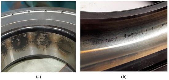
Figure 1.
Irregular pitting of the bearing caused by the flow of bearing currents on the inner surface of the bearing (a) and the inner surface of the outer race of the bearing (b).
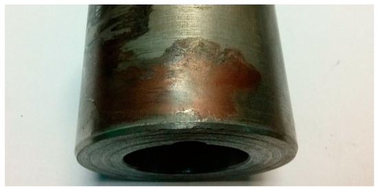
Figure 2.
Damage to the outer surface of the shaft journal.
The available scientific and technical studies quite broadly describe the potential causes of shaft voltages in electrical machines and categorize their nature. The basic criterion for classifying the causes of generating shaft voltages in electric machines is the method of their power supply. There are different mechanisms of generating bearing voltages and currents if the machine is supplied with sinusoidal voltage or if it is supplied from a power electronic converter. Therefore, subsequent text, the causes, and methods of eliminating this phenomenon are presented separately for different power supplies of the machine.
1.1. Reasons for the Occurrence of Bearing Currents in Electric Machines with Sinusoidal Voltage Supply and Methods of Their Elimination
In the case of supplying an electric machine from the mains, the main reason for the generation of shaft voltage is the asymmetry of the electromagnetic circuit. It can result from both the technological tolerances of the machine as well as from the damages that are the consequence of the operation. Among the most important reasons are [5]: asymmetry of the air gap (dynamic or static), uneven air gap along the axis of the machine caused by the bending of the rotor (the primary cause is, for example, uneven magnetic tension along the shaft), inaccuracies in the execution of the stator and/or rotor iron core, anisotropy of the stator/rotor package sheets, ventilation channels in the stator and/or rotor package, stator sheets segmentation, asymmetry caused by short-circuit of a stator or rotor sheets, turn short-circuits in the windings, as well as cracks in the bars of the induction machine cage or its end rings.
The above reasons lead to the appearance of a circular flux in the stator’s yoke, which is the effect of the asymmetry of the main flux in the electromagnetic circuit [8]. This time-varying magnetic flux surrounding the machine shaft induces a shaft voltage which is the source of the current flowing through the shaft and the machine bearings. The publication [9] presents the idea of limiting shaft voltages based on the damping of this flux. For this purpose, an auxiliary winding was used, which was wound around the stator yoke. Magnetic flux asymmetry in the machine circuit results in inducing voltage at the terminals of the open auxiliary winding. When this winding is short-circuited, a current flows, which compensates the circular flux in the stator yoke, thus limiting the voltage on the machine shaft.
One of the methods of eliminating shaft currents in electric machines is the use of ceramic bearings (in which both raceways and rolling elements are ceramic) or hybrid bearings (only the rolling elements are made of a ceramic material) [3]. In such bearings, we obtain a large dielectric barrier along the path: shaft—bearings—bearing shields—frame.
1.2. Reasons for the Occurrence of Bearing Currents with Inverter Power Supply
The development of power electronic converters supplying electric motors contributed to the overall development of drive systems, enabling their operation at high supply frequencies, up to 1000 Hz [10]. One of the main sources of disturbances in drive systems is circuits with IGBT and MOSFET transistors. The issues mainly result from the high steepness (rise rate) of voltage and current growth that are present in the input and output circuits of the inverter. Fast switching of transistors in inverters contributes to the emergence of many unintentional phenomena, which include, among others: imbalance voltage caused by feeding the machine windings with distorted voltage, bearing voltages and currents, shaft voltages and currents, earth currents in grounded motors, decrease in motor efficiency, as well as the emission of electromagnetic disturbances. Due to the rapid development of technology, ever-newer methods of counteracting negative phenomena are currently being sought, not only through the use of appropriate filters but also through their elimination at the stage of designing the drive system. In order to improve the control conditions of AC electric machines powered by inverters, high control frequencies (up to several kHz) are used. Controlling the transistors with such high switching frequencies significantly reduces the noise generated in the drive system and makes it possible to obtain a sinusoidal shape of the current consumed by the motor. Nevertheless, if the switching frequency of the inverter power transistors is too high, it contributes to the excessive dissipation of power losses caused by the increased share of dynamic losses in relation to the static losses in the inverter while reducing the power losses generated in the electric machine.
Most of the frequency converters working with asynchronous and synchronous machines with permanent magnets work with the use of the space vector modulation (SVM) method, which enables independent regulation of speed and electromagnetic moment. Unlike machines powered by the sinusoidal voltage, the use of semiconductor power electronic systems is associated with the presence of non-zero voltage at the neutral point of the machine winding related to the earth’s potential. This voltage, referred to as common-mode voltage, is the average sum of the instantaneous voltage values (1) (asymmetric, rectangular voltage waveforms) at the converter output resulting from the use of pulse width modulation. The most frequently used inverters in drive systems with induction and synchronous machines are the three-branch two-level voltage inverters with adjustable amplitude and frequency. The scheme of the inverter is shown in Figure 3. In such inverters, the DC-link voltage is switched via the two-state power elements of the inverter (S1–S6). Each branch of the three-phase inverter can assume two different operating states while one of the two power valves of the inverter branch is turned on at a given moment. Thus, the three branches of the inverter can generate eight possible state combinations, represented by eight separate voltage vectors at the inverter power outputs.
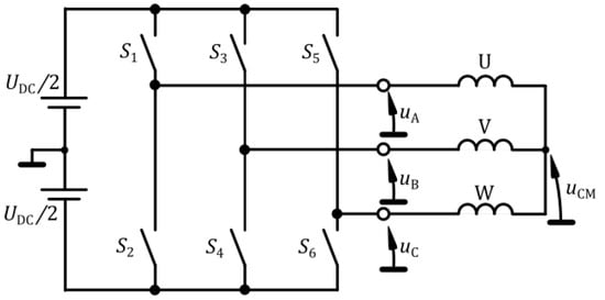
Figure 3.
Schematic diagram of a two-level three-phase frequency converter with specified common-mode voltage uCM.
The basic control algorithm of the two-level power electronic converter consists of the appropriate control of six power electronic switches S1–S6, as shown in Table 1, which leads to the generation of the space vector of the output voltage. Figure 4 shows examples of phase voltages uA, uB and uC created with the use of the available operating states of the inverter switches. In each of them, there is an asymmetry of the output voltages, which results in the formation of common-mode voltage uCM (Figure 3). Thus, the resultant voltage uCM appears at the neutral point of the stator winding, which is expressed by the Formula (1):

Table 1.
Summary of the common-mode voltage uCM values for individual control vectors.
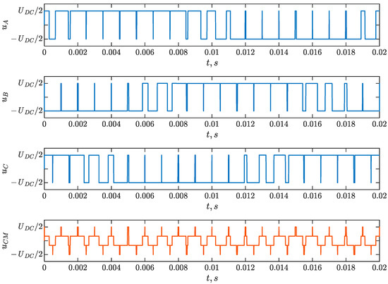
Figure 4.
Sample waveforms of the phase output voltages of a two-level frequency converter uA, uB, uC and the common-mode voltage uCM.
The common-mode voltage has the form of a step function of time with a maximum value equal to half of DC-link voltage UDC. The value of the voltage change on individual steps is 1/3 UDC; this is alternating voltage, with a frequency dependent on the switching frequency. The use of switches with short switching times (e.g., IGBT transistors) results in voltage rise rates in the inverter output voltages and the common-mode voltage, up to 10 kV/μs [11], especially in the case of using converters based on the SiC technology [12].
Rapid voltage increase duCM/dt at the neutral point of the stator winding stimulates the occurrence of capacitive couplings in the electrical machine and plays an important role in the mechanism of generating bearing currents. The stator windings of the electric machine are isolated from the stator core, and at the same time, the rotor is practically isolated from other structural elements due to the presence of an oil film in the bearings. As a consequence, a capacitance system is created between the structural elements of the motor, which in the subsequent text are referred to as the internal capacitances of the machine. The electrodes of these internal capacitances are the stator winding, stator and rotor cores, and their dielectrics are, among others, slot insulation, air gap, and oil film in the bearings. In the simplified model of the electric machine, the following capacitances can be distinguished: Cws—capacitance between the stator winding and the grounded stator; Cwr—capacitance between the stator winding and the rotor; Csr—capacitance between the rotor and the grounded stator; Cb1 and Cb2—bearing capacitances on the drive and non-drive end. The spatial location of the above-mentioned capacitances is illustrated in the cross-section of the electric machine in Figure 5. The topology and connection of these capacitances in the form of an equivalent circuit with lumped parameters are shown in Figure 6a [13].
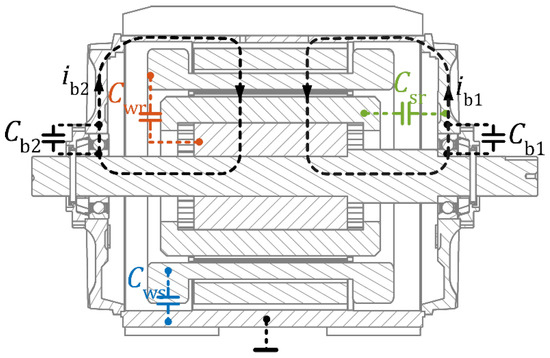
Figure 5.
Internal capacitances in the electric machine.
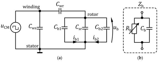
Figure 6.
(a) Equivalent circuit diagram for the flow of the bearing current; uCM—common-mode voltage, ub—bearing voltage, description of other parameters in the text, (b) equivalent circuit of the bearing impedance Zb, composed of: bearing resistance Rb and capacitance Cb.
The value of the Cws capacitance depends on the geometrical dimensions of the machine and the configuration of the windings, as well as on the dielectric parameters of the used stator slot insulation, while the value of the capacitance Cwr depends on the shape and dimensions of the electromagnetic circuit. In terms of the electrical circuit, bearings are represented by impedance Zb that consists of a parallel connection of resistance Rb and capacitance Cb (Figure 6b).
The values of these parameters depend on the bearing structure, temperature, and the operating condition of the machine. During the normal operation of the machine, an oil film forms dielectric insulation between the rolling elements and raceways of the bearing. If lubricant is of poor quality or altogether missing, then if a voltage higher than the breakdown voltage appears, the impedance Zb is short-circuited. In the case of a stopped rotor, the bearing raceways are short-circuited by the rolling elements (no oil filter present), which causes a significant decrease in the resistance Rb. This condition is especially dangerous for the bearing when the motor is started. When the impedance Zb is short-circuited, a bearing current ib flows under the bearing voltage ub. The values of the equivalent circuit parameters can be determined by measurement, analytically [14,15] or using the finite element method. The bearing resistances are omitted here; an equivalent diagram that consists only of internal capacitances is used.
The equivalent diagram (Figure 6) shows that the common-mode voltage uCM is the source of the voltage between the bearing raceways ub. The ratio of these voltages (BVR—Bearing Voltage Ratio) is given by the Equation (2) [16]:
It is worth emphasizing that when the motors are supplied with sinusoidal voltage with the mains frequency f = 50 Hz, the internal impedances/reactances of the machine are very high (Xc = 1/ωC), and they are not significant in generating bearing voltages. The values of internal capacities are at the level of a few nF. They are important only when the machine windings are supplied from inverters, where voltage rise rates are high; therefore, the knowledge of their values is of fundamental importance from the point of view of determining, e.g., the values of bearing voltages.
2. Methods of Limiting Bearing Voltages When Powering the Machine from an Inverter
2.1. Changing Power Source Parameters
When powering an electric machine from a power electronic converter, one of the methods of limiting the bearing currents is limiting the amplitude and the voltage rise rate of the common-mode voltage uCM.
The use of shielded power cables between the converter and the electrical machine plays a very important role in limiting the imbalance of voltage and bearing currents [17].
The common-mode voltage uCM can be limited using modified converter control algorithms. In a two-level converter, the highest uCM voltage occurs for the zero vectors of the control algorithm (converter switch state combinations: 000 or 111) and is equal to half the voltage value in the DC-link circuit (see Table 1). Removing zero vectors from the control strategy significantly reduces the uCM voltage, lowering its amplitude value to 1/3 UDC. Unfortunately, the missing zero vectors must be replaced with other active vectors, which increases the content of higher harmonics in the converter current, complicating the internal current measurement in the converter.
On the other hand, the use of a multi-level converter significantly reduces the uCM voltage. Compared to a two-level power electronic converter, a three-level converter requires the use of twelve IGBTs (each phase of the converter contains four transistors). The use of an appropriate algorithm for controlling such an inverter enables the reduction of the uCM voltage amplitude to the value of UDC/3 [18].
The limitation of the impact of power electronic frequency converter supply on the bearing life can also be executed by lowering the switching frequency and thus reducing the number of uCM voltage steep edges. Unfortunately, this may adversely affect the value of the electromagnetic torque and increase the active power losses generated in the machine’s structural elements [19].
Other methods of dealing with the phenomenon of shaft currents occurring when the machine is powered from an inverter are solutions aimed at equalizing the potentials of the rotor and the frame. This may be performed, for instance, by mounting special shorting rings, brushes, or copper strips. This solution forces the flow of currents to bypass the critical elements—bearing mostly. An interesting concept is presented in [20]; it shows that there is such a value of the impedance of rotor grounding, for which the BVR coefficient takes the minimum value.
2.2. Methods Based on Changes in the Design of the Machine
When considering the model of internal capacitances shown in Figure 6, in an electric machine with permanent magnets, three characteristic points with different potentials can be distinguished:
- grounded motor frame with stator iron core;
- the winding located in the slots of the stator iron core and outside it (so-called end-connections) with the potential of the common-mode voltage uCM;
- rotor with a potential depending on the value of the internal capacitances of the machine and common-mode voltage.
Equation (2) shows that the bearing voltage is directly proportional to the internal capacitance between the stator winding and the rotor. Consequently, one of the methods of limiting bearing voltages is to minimize them by modifying the design of the machine. The capacitance between the winding and the grounded stator is not involved in the mechanism of generating voltage between the bearing raceways—it only affects the value of the current flowing from the uCM source. For example, the Cwr capacitance can be reduced by increasing the thickness of the air gap between the stator and rotor. However, such a solution may adversely affect the operational parameters of the machine [21].
The reduction of Cwr can also be executed by using an electrostatic shield placed in the space between the stator winding and the rotor. The solutions described in the literature include the cases of shielding winding along the entire length of the stator iron core [22,23] as well as shielding of end-windings [24,25].
The internal capacitance Cwr can also be reduced by moving the stator winding away from the rotor. This idea was presented in the article [26], where the authors suggested a change in the slot insulation and an increase in the thickness of the slot wedge. It was demonstrated on the basis of simulations and measurements that increasing the distance between the stator winding and the rotor surface by 76% resulted in a reduction of the BVR coefficient by more than 50%.
Another method of limiting the internal capacitance of the machine between the winding and the rotor based on structural changes is the use of an oblique opening of the stator slot [27]. On the basis of a series of FEM simulations carried out by the authors, it was shown that, compared to the reference structure, the use of the oblique opening of the stator slot combined with a simultaneous reduction of its width made it possible to reduce the capacitance between the stator winding and the Cwr rotor by about 98%; the phenomena occurring in the area of end-windings were neglected. It is worth adding that the modification of the shape of the stator slot practically did not affect the operational parameters of the machine.
What is also worth mentioning is that a separate method of preventing bearing damage is to use at least one insulated bearing (fully ceramic or hybrid) [28]. The authors of the article [29] presented, among others, results of simulation tests, which showed a significant reduction of the shaft voltage by introducing an insulating layer between the bearing and the machine shaft. This reduction attained 70%.
Another method of reducing the Cwr capacitance is a solution based on shielding the stator winding in the slots. This is the subject of the tests described in the next section.
The Idea of a Shielding Winding Placed in a Slot Wedge
The previously described method of limiting the bearing voltage that is based on reducing the capacitance between the stator winding and the rotor can also be executed by placing a grounded conductor in the stator slot opening space. The idea suggested by the authors is to place copper wires inside the wedges, as shown in Figure 7. Individual wires are placed along the entire length of the wedge and are connected in series to form one winding, and their frontal connections can be made by soldering. Importantly, only one end of the winding formed in such a way is grounded. Depending on the geometrical dimensions of the wedge, more shielding wires can be used. In the presented solution, the wedge not only protects the stator winding against falling out but also acts as an insulation between the stator winding and the grounded shielding wires. The above solution is simple to implement and can be used in cases where high reliability of the drive system operation is required.
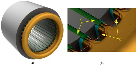
Figure 7.
(a) Wound stator with a shielding winding placed in the slot wedges, (b) Fragment of the stator iron core with visible shielding winding connections; 1—stator end-winding, 2—slot wedges, 3—connections of shielding wires placed in wedges.
The rest of the article presents the results of simulation tests and the analysis of various designs, including the use of a shielding winding.
3. Simulation Analysis of Various Designs Aimed at Limiting Internal Capacitance Cwr
In order to analyze the possibility of introducing design changes to the electric machine aimed at limiting the internal capacitance between the stator winding and the rotor, a two-dimensional model of the machine was developed in the Ansys Maxwell 2D using the finite element method [30]. Simulation tests make it possible to carry out multivariant calculations in order to determine the optimal design of the machine that will be used to prepare the real model. Conducting laboratory tests requires the development and implementation of a number of machine prototypes, which entails considerable costs. In order to determine the internal capacitances of the machine, calculations were carried out in the Electrostatic solver. It should be borne in mind that the adoption of a two-dimensional model of the machine for calculations is associated with neglecting the capacitances between the end winding and the rotor. The field model of the reference design of the surface-mounted PM synchronous machine is shown in Figure 8, and the finite element mesh consisting of 65,900 triangular elements is shown in Figure 9.
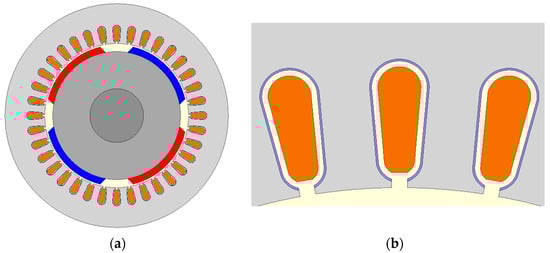
Figure 8.
Two-dimensional reference simulation model for determining internal machine capacitances: (a) complete model view, (b) shaping the stator slot and winding.
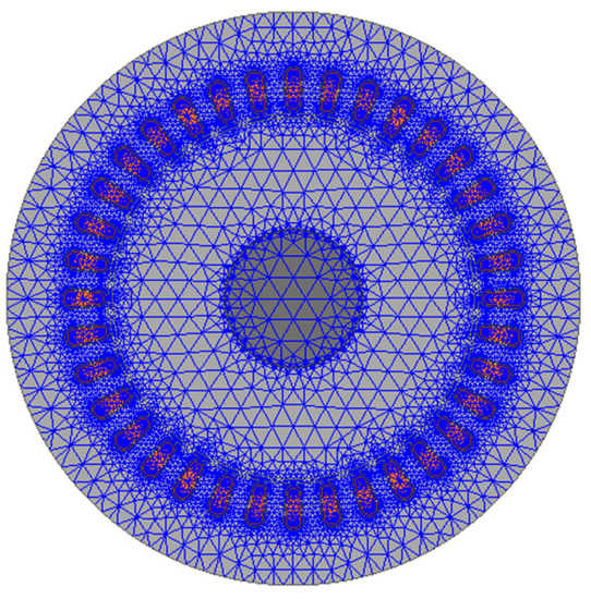
Figure 9.
Finite element mesh of the reference field model.
The ratings of the machine analyzed here are: PN = 7 kW, IN = 400 V, shaft height h = 132 mm, number of pole pairs p = 2, type of winding: three-phase, single-layer, distributed in 36 slots. The aim of the research is to analyze the impact of changes in the dimensions and shape of the slot opening and placing the shielding wire in the slot opening space, as well as to determine the impact of changes in the electrical permeability of the material from which the wedge is made on the internal capacitances of the machine. The analysis of the impact of these design changes on the internal capacitances of the machine is presented in the following sections of the article.
3.1. Changing the Slot Opening Width
The first case under consideration included the analysis of the influence of the change of the slot opening width Bs0 on the internal capacitances of the machine, which is demonstratively presented in Figure 10. Figure 11a,b shows the calculated characteristics of the capacitances: Cwr, Cws, Csr.
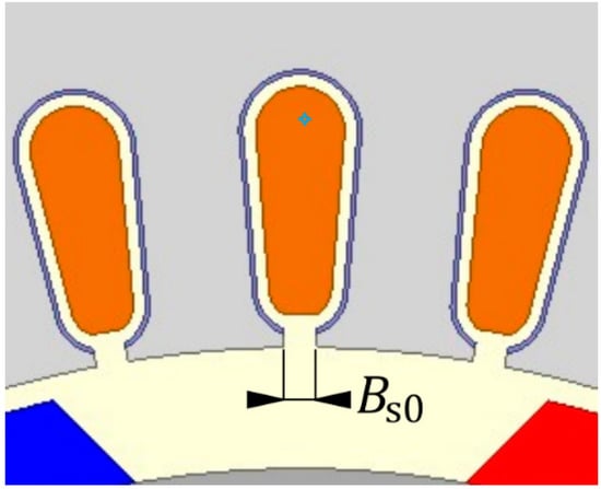
Figure 10.
The shape of the analyzed stator slot with the marked opening width Bs0.
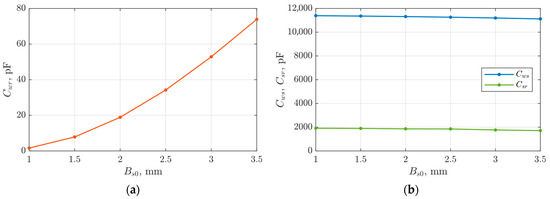
Figure 11.
Characteristics of capacitance changes: (a) Cwr, (b) Cws and Csr depending on the slot opening width Bs0.
The simulation tests show that the reduction of the slot opening width Bs0 causes the reduction of the Cwr capacitance. Other capacitances remain practically unchanged. It is worth emphasizing here that, in general, case changes in the shape of the slot of a ferromagnetic core are related to changes in the parameters of the electromagnetic circuit of the machine. Moreover, from a technological point of view, the reduction of the slot opening makes the stator winding process more difficult. In addition, the use of a fully open stator slot [31] may increase the Cwr capacitance, exposing the machine bearings to unsafe levels of voltage ub. For the reference model, the slot opening Bs0 is 2 mm, and the capacitance between the stator winding and the rotor is 19 pF. This value is treated later in the article as a reference value.
3.2. Shielding Wire Placed in the Slot Wedges—Variant B
The second analyzed variant was divided into two cases. In the first case, to limit the internal capacitance of the machine between the stator winding and the rotor, a screen in the form of a copper wire placed inside the wedge closing the slot was used. The cases for one Ns = 1 and two shielding wires Ns = 2 (wire diameter was d = 0.4 mm) placed in the wedge were analyzed. The two-wire model is shown in Figure 12. The wires of the shielding winding with the wedge are located in each slot in the stator, and the potential of the wires is connected to the ground.
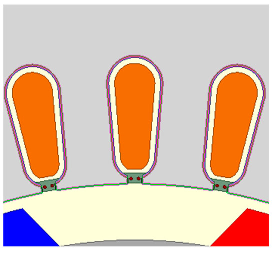
Figure 12.
Fragment of the field model with the use of shielding wires inside the stator wedges.
The analyzed variant (B) was divided into two cases. In the first one, the influence of the shielding winding on internal capacitances for different stator slots opening width was determined with the identical arrangement of the shielding wires in wedges with constant permittivity εr = 1. The results of the calculations are presented in Figure 13a,b. They show that the shielding winding reduces the value of the Cwr capacitance in the entire range of the slot opening width variability. With the increase in the slot opening width Bs0, the ratio of the stator wedge cross-section Sw to the total cross-section of the shielding wires Ssh increases. This contributes to a reduction in the effectiveness of the shielding winding. For example, for two different slot opening widths Bs0 = 2 mm and Bs0 = 3.5 mm (Ns = 1), respectively, over 6-fold and 3-fold reduction in the value of the Cwr capacitance compared to the reference model was obtained. The remaining internal capacitances Cws and Csr slightly decrease with the increase in the slot opening width.
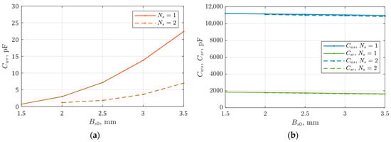
Figure 13.
Characteristics of capacitance changes: (a) Cwr, (b) Cws and Csr depending on the slot opening width Bs0 and the number of grounded shielding wires (εr = 1).
In the second case, the influence of electric permeability on the internal capacitances of the machine was analyzed. The calculations presented in Figure 14a,b show that, compared to the reference model, the Cwr capacitance value decreased by more than six times for the case of a single shielding wire and by about 20 times for the application of two shielding wires inside the wedge. It is also worth noting that the value of the capacitance decreases as the relative permeability of the wedge material increases. For example, it can be mentioned that for the relative permeability of the wedge εr = 5, a reduction in capacitance by another 30% can be observed compared to the permeability of εr = 1. The remaining internal capacitances Cws and Csr for the analyzed electric permeability do not show significant changes.
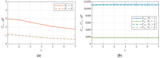
Figure 14.
Characteristics of capacitance changes: (a) Cwr, (b) Cws and Csr depending on the value of the electric permeability of the wedge closing the slot and the number of grounded shielding wires. (Bs0 = 2 mm).
It is worth mentioning that in practice, slot wedges made of magnetic materials are sometimes used to improve the operational properties of the machine [32]. However, they do not change the Cwr capacitance.
3.3. Oblique Slot Opening—Variant C
The reference model presented in Section 3.1. has been modified by changing the parameters of the oblique slot. The influence of oblique slot opening and its width on the capacitance Cwr has been analyzed, and results may be found in [27]. By changing the shape of the teeth, the area through which the electric charge can pass from the stator winding to the rotor is limited. This procedure changes the distribution of the main flux and leakage flux, thus affecting the electromechanical parameters of the machine. This article analyzes the effect of the width of the oblique opening of the slot Bs0′ with the angle of inclination α = 45°, as shown in Figure 15. The slot opening width significantly affects the value of the Cwr capacitance (same as in the reference model); this is seen in Figure 16a,b. For the standard width of Bs0′ = 2 mm, a capacitance reduction of 30% was obtained. In this case, it should be noted that the use of the oblique opening of the slot causes additional difficulties in the manual and automatic winding of the stator core.
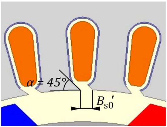
Figure 15.
Fragment of a field model with oblique slot opening.
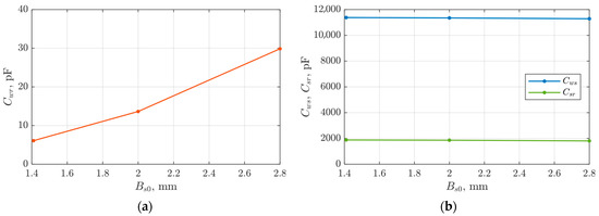
Figure 16.
Characteristics of capacitance changes: (a) Cwr, (b) Cws and Csr depending on the width of the oblique opening of the slot.
3.4. Shielding Winding Placed in Wedges Located in Oblique Slot Openings—Variant D
A further modification is introduced by combining together the variants presented in Section 3.2 and Section 3.3. This is a design shown in Figure 17. In this case, both the oblique slot opening and slot wedges with 0.4 mm shielding wires were used. Simulation calculations were performed for different slot opening widths Bs0′ as well as for a different number of shielding wires in the wedge (NS = 1 and NS = 2).
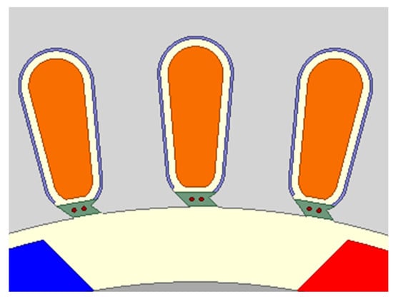
Figure 17.
Fragment of a field model with an oblique slot opening.
The simulation results are shown in Figure 18a–d. As with a straight slot opening, also, in this case, a significant decrease in capacitance Cwr can be observed when the number of wires in the wedge is increased, and the electric permeability of the wedge is raised. These changes do not significantly affect the capacitances values Cws and Csr—electric field lines between these elements do not close by the slot opening space. This design combines the advantages of the variants presented in Section 3.2 and Section 3.3 (variants B and C). It is noteworthy that the increase in Cwr due to the increase in slot opening width can be compensated using additional shielding wires in the slot wedge.
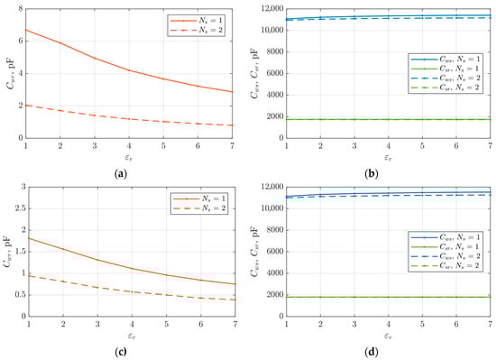
Figure 18.
Characteristics of capacitance changes: (a) Cwr (Bs0′ = 2.8 mm), (b) Cws and Csr (Bs0′ = 2.8 mm), (c) Cwr (Bs0′ = 2 mm), (d) Cws and Csr (Bs0′ = 2 mm) depending on the width of the oblique openings of the slots and the electric permeability of the wedges.
4. Summary of Calculation Results Obtained by FEM Simulation
For the purpose of assessing the effectiveness of the analyzed designs, the coefficient kBVR, expressed by the Formula (3), was introduced, defining the change in the BVR coefficient in relation to the reference design. The results of simulation tests of the considered design variants and methods of limiting the internal capacitance between the stator winding and the machine rotor are summarized in Table 2. It presents, respectively, the values of the capacitance Cwr and the coefficient kBVR expressed by the Formula (3):
where:
Table 2.
Summary of computer simulation results.
- BVRref—Bearing Voltage Ratio of reference model (variant A at Bs0 = 2 mm);
- BVR—Bearing Voltage Ratio of analyzed variant.
The reference model was the variant in which no shielding winding was used, and the slot opening was 2 mm. For the calculation of the coefficient kBVR the value of the bearing capacitances was assumed to be Cb1 = Cb2 = 100 pF [33,34]. All variants apply to identical geometrical dimensions of the electromagnetic circuit (except for the slot opening), the stator winding, the air gap, and the diameter of the shielding winding wires. The presented results of the simulation tests show that placing the grounded shielding wires in the slot opening space has a positive effect on limiting the capacitance Cwr. It proved to be particularly advantageous to use two shielding wires in the stator slot wedge (Ns = 2). Due to the slight differences between variants B and D and technological problems related to the change of the stator geometry, it was decided that the optimal variant was variant B with two shielding wires in each slot wedge. The main assumption for which this solution was called optimal was due to, among others, the lack of need to redesign the shape of the stator ferromagnetic core and any difficulties associated with the winding of the stator iron core.
5. Estimation of Bearing Voltages Based on the Circuit Model of the Inverter and the Internal Capacitances of the Machine
In order to estimate the value of the voltage between the bearing raceways, a circuit model was developed in the Matlab/Simulink environment shown in Figure 19. It consists of three parts: the inverter, the three-phase motor winding, and the internal capacitances of the motor determined by the finite element method.
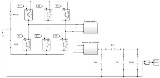
Figure 19.
Diagram of a circuit model to simulate the bearing voltage ub.
A two-level power electronic converter consisting of six IGBT transistors was considered. The model uses simplified models of transistors [35] available in the Matlab/Simulink environment with the following parameters: Ron = 1 mΩ and Rs = 1 MΩ. The inverter is powered by a DC voltage source UDC, which is split into two parts to form a midpoint. The inverter is powered from a DC voltage source of 565 V, as is the case in the DC-link circuit in standard frequency converters powered from the 3 × 400 V electrical grid. The SVM (space vector modulation) method was used to control the six IGBT transistors. The individual switching states of the transistor keys (S1–S6) of the frequency converter correspond to the space voltage vectors: six active and two zero vectors, presented in Table 1. The output voltage is obtained by the appropriate switching of the active and zero vectors. A three-phase symmetrical stator winding of a permanent magnet synchronous machine was connected to the inverter output, represented by three identical series resistive-inductive circuits. The phases of the stator winding of the machine were star connected. By using three identical resistances, an artificial neutral point was created at the inverter output, to which the circuit of the internal capacitances of the analyzed machine, described in Section 1.2, was connected: Cwr, Cws, Csr, and two bearing capacitances Cb = 100 pF. The circuit model did not take into account, among others, the parameters of the cable connecting the inverter with the motor, as well as the parameters of the earthing conductor. At the output of the voltage divider formed in such a way, a measuring element was placed in order to observe the bearing voltage ub. The waveforms of bearing voltages obtained on the basis of the described circuit model for the reference and optimal solutions are shown in Figure 20.
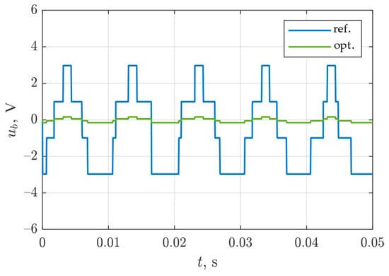
Figure 20.
Comparison of bearing voltages for a reference and optimal solution.
While comparing the obtained results of simulations, a significant reduction in the amplitude of the bearing voltage can be observed. The amplitudes of this voltage are respectively: 3.12 V for the reference model and 0.16 V for the optimal solution.
Bearing voltage causes charging of bearing capacitance Cb. As a result of exceeding the breakdown voltage of a thin oil film layer, this capacitance is discharged in the bearing, resulting in bearing discharge currents. Voltages ub lower than 0.3 V are considered safe, while voltages in the range from 0.5 V to 1 V contribute to the development of dangerous bearing currents. Voltages ub greater than 2 V may cause premature bearing failure [36]. Thus, in electrical machines, where bearing voltages exceed the value of 2 V, one should take into account the accelerated wear of the bearings caused by the phenomenon of electro-corrosion.
6. Discussion and Conclusions
In drive systems powered by inverters, parasitic phenomena occur in the motor itself. Among them are bearing discharge currents, which pose a serious threat to the operation of bearings. Limiting the effect of the occurrence of bearing discharge currents can be ensured not only by the appropriate selection of the inverter switches control algorithm but also by modifying the design of the machine’s electromagnetic circuit.
In the article, a series of computer simulations using the FEM method were carried out to investigate the impact of various designs of the permanent magnet synchronous machine (PMSM) on internal capacitances, in particular on the Cwr capacitance between the stator winding and the rotor, which largely determines the levels of the generated bearing voltages. In particular, we analyzed a case of the effect of using a single-side grounded shielding winding placed inside the stator slot wedges.
For each of the analyzed variants, a significant reduction in Cwr capacitance was obtained when shielding winding was used. In practice, the number of wires used within the opening of one slot is limited by the space available and the cross-sectional area of the shielding wire. The use of wedges with greater electric permeabilities contributes to a further but insignificant reduction in capacitance. In practice, dielectric composite materials based on glass fibers and epoxy resin are often used for the production of slot wedges [37]. Depending on the material used, there are wedges with a relative permeability ranging from 1.5 to 5.5 [37,38]. The analysis of the presented research results shows that the largest absolute limitation of the capacitance was obtained when the oblique opening of the stator slot was used. However, this solution is limited to newly designed machines and requires the construction of a new stator electromagnetic circuit. In practice, this means the development and production of a new sheet metal punch, which means additional costs. The optimal solution presented in the article does not require any structural changes to the electromagnetic circuit and is only limited to placing the shielding winding in the stator slot wedges. It is worth noting that the simulations carried out concerned only the capacitances on the active length of the packet—the capacitance between the winding faces and the rotor was not taken into account here. The available literature [39] states that the share of capacitances between the end windings and the rotor Cwr(ew) in the total capacitance Cwr(total) for machines with a power of 10 kW is approximately 40%. In view of the above, striving to reduce the Cwr capacitance as much as possible along the length of the machine stator core does not result in a noticeable change in the BVR coefficient. According to the authors of the article, the suggested design based on the use of shielding winding (the connections of these wires are located in the space under the main end-winding) may have a positive effect on limiting the capacitance Cwr(ew).
Summarizing the results collected in Table 2 and taking into account the technological aspects mentioned above, the optimal design was to use two shielding wires placed in a slot wedge made of dielectric material with a relative electric permeability εr = 5—variant B (Ns = 2). This design reduced the bearing voltage by 96% compared to the reference variant.
In further research, it is planned to continue simulation studies extended to three-dimensional models and to conduct laboratory tests using a prototype model of an electric machine.
Author Contributions
Conceptualization, S.B. and T.J.; methodology, S.B. and T.J.; simulations, S.B. and T.J.; writing—review and editing, S.B. and T.J.; visualization, S.B. and T.J. All authors have read and agreed to the published version of the manuscript.
Funding
The research is co-financed under the Program of the Ministry of Science and Higher Education “Implementation Doctorate” (Poland).
Institutional Review Board Statement
Not applicable.
Informed Consent Statement
Not applicable.
Data Availability Statement
Not applicable.
Conflicts of Interest
The authors declare no conflict of interest.
References
- Kudelina, K.; Asad, B.; Vaimann, T.; Rassõlkin, A.; Kallaste, A.; Khang, H.V. Methods of Condition Monitoring and Fault Detection for Electrical Machines. Energies 2021, 14, 7459. [Google Scholar] [CrossRef]
- Deekshit Kompella, K.C.; Venu Gopala Rao, M.; Srinivasa Rao, R. Bearing Fault Detection in a 3 Phase Induction Motor Using Stator Current Frequency Spectral Subtraction with Various Wavelet Decomposition Techniques. Ain Shams Eng. J. 2018, 9, 2427–2439. [Google Scholar] [CrossRef]
- SKF. SKF Bearing Maintenance Handbook; SKF: Göteborg, Sweden, 2011; ISBN 978-91-978966-4-1. [Google Scholar]
- Timken Bearing Damage Analysis with Lubrication Reference Guide; The Timken Company: North Canton, OH, USA, 2015.
- Costello, M.J. Shaft Voltages and Rotating Machinery. IEEE Trans. Ind. Appl. 1993, 29, 419–426. [Google Scholar] [CrossRef]
- Zhou, Y.; Bosman, R.; Lugt, P.M. An Experimental Study on Film Thickness in a Rolling Bearing for Fresh and Mechanically Aged Lubricating Greases. Tribol. Trans. 2019, 62, 557–566. [Google Scholar] [CrossRef]
- Plazenet, T.; Boileau, T.; Caironi, C.; Nahid-Mobarakeh, B. An Overview of Shaft Voltages and Bearing Currents in Rotating Machines. In Proceedings of the 2016 IEEE Industry Applications Society Annual Meeting, Portland, OR, USA, 2–6 October 2016; pp. 1–8. [Google Scholar]
- Chapter 2 Shaft voltages and their origin in rotating machines and flow of electric current through bearings. Tribol. Interface Eng. Ser. 2006, 49, 15–23.
- Berhausen, S.; Jarek, T. Method of Limiting Shaft Voltages in AC Electric Machines. Energies 2021, 14, 3326. [Google Scholar] [CrossRef]
- Wolnik, T.; Styskala, V.; Mlcak, T. Study on the Selection of the Number of Magnetic Poles and the Slot-Pole Combinations in Fractional Slot PMSM Motor with a High Power Density. Energies 2021, 15, 215. [Google Scholar] [CrossRef]
- Turzyński, M.; Musznicki, P. A Review of Reduction Methods of Impact of Common-Mode Voltage on Electric Drives. Energies 2021, 14, 4003. [Google Scholar] [CrossRef]
- Collin, R.; Yokochi, A.; von Jouanne, A. Novel Characterization of Si- and SiC-Based PWM Inverter Bearing Currents Using Probability Density Functions. Energies 2022, 15, 3043. [Google Scholar] [CrossRef]
- Muetze, A.; Binder, A. Calculation of Motor Capacitances for Prediction of the Voltage Across the Bearings in Machines of Inverter-Based Drive Systems. IEEE Trans. Ind. Appl. 2007, 43, 665–672. [Google Scholar] [CrossRef]
- Stockbrügger, J.O.; Ponick, B. Analytical Determination of the Slot and the End-Winding Portion of the Winding-to-Rotor Capacitance for the Prediction of Shaft Voltage in Electrical Machines. Energies 2020, 14, 174. [Google Scholar] [CrossRef]
- Muetze, A.; Binder, A. Calculation of Circulating Bearing Currents in Machines of Inverter-Based Drive Systems. IEEE Trans. Ind. Electron. 2007, 54, 932–938. [Google Scholar] [CrossRef]
- Ahola, J.; Muetze, A.; Niemela, M.; Romanenko, A. Normalization-Based Approach to Electric Motor BVR Related Capacitances Computation. IEEE Trans. Ind. Appl. 2019, 55, 2770–2780. [Google Scholar] [CrossRef]
- Luszcz, J. Motor Cable Effect on the Converter-Fed AC Motor Common Mode Current. Przegląd Elektrotechniczny 2012, 88, 177–181. [Google Scholar]
- Zare, F.; Adabi, J.; Ghosh, A. Different Approaches to Reduce Shaft Voltages in AC Generators. In Proceedings of the 2009 13th European Conference on Power Electronics and Applications, Barcelona, Spain, 8–10 September 2010; pp. 2582–2590. [Google Scholar]
- Hadden, T.; Jiang, J.W.; Bilgin, B.; Yang, Y.; Sathyan, A.; Dadkhah, H.; Emadi, A. A Review of Shaft Voltages and Bearing Currents in EV and HEV Motors. In Proceedings of the IECON 2016—42nd Annual Conference of the IEEE Industrial Electronics Society, Florence, Italy, 23–26 October 2016; pp. 1578–1583. [Google Scholar]
- Yang, L.; Yang, Y.; Wen, J.; Jia, L.; Yang, E.; Liu, R. Suppression of Rotor-Grounding Bearing Currents Based on Matching Stator and Rotor Grounding Impedances. Energies 2022, 15, 1638. [Google Scholar] [CrossRef]
- Hu, X.; Li, Y.; Luo, L. The Influence of Air Gap Thickness between the Stator and Rotor on Nuclear Main Pump. Energy Procedia 2017, 142, 259–264. [Google Scholar] [CrossRef]
- Ferreira, F.J.T.E.; Cistelecan, M.V.; de Almeida, A.T. Slot-Embedded Partial Electrostatic Shield for High-Frequency Bearing Current Mitigation in Inverter-Fed Induction Motors. In Proceedings of the XIX International Conference on Electrical Machines—ICEM 2010, Rome, Italy, 6–8 September 2010; pp. 1–6. [Google Scholar]
- Alves Êvo, M.T.; Paula, H. Electrostatic Shielding for Bearings Discharge Currents Attenuation: Analysis of Its Effectiveness, Losses and Impact on the Motor Performance—A Study for Design Guidelines. IET Electr. Power Appl. 2020, 14, 1050–1059. [Google Scholar] [CrossRef]
- Gerber, S.; Wangi, R.-J. Reduction of Inverter-Induced Shaft Voltages Using Electrostatic Shielding. In Proceedings of the 2019 Southern African Universities Power Engineering Conference/Robotics and Mechatronics/Pattern Recognition Association of South Africa (SAUPEC/RobMech/PRASA), Bloemfontein, South Africa, 28–30 January 2019; pp. 310–315. [Google Scholar]
- Magdun, O.; Gemeinder, Y.; Binder, A. Prevention of Harmful EDM Currents in Inverter-Fed AC Machines by Use of Electrostatic Shields in the Stator Winding Overhang. In Proceedings of the IECON 2010—36th Annual Conference on IEEE Industrial Electronics Society, Glendale, AZ, USA, 7–10 November 2010; pp. 962–967. [Google Scholar]
- Vostrov, K.; Pyrhonen, J.; Niemela, M.; Ahola, J.; Lindh, P. Mitigating Noncirculating Bearing Currents by a Correct Stator Magnetic Circuit and Winding Design. IEEE Trans. Ind. Electron. 2021, 68, 3805–3812. [Google Scholar] [CrossRef]
- Yea, M.; Han, K.J. Modified Slot Opening for Reducing Shaft-to-Frame Voltage of AC Motors. Energies 2020, 13, 760. [Google Scholar] [CrossRef]
- Current-Insulating Bearings; Schaeffler Technologies AG & Co., KG: Yokohama, Japan, 2020.
- Han, P.; Heins, G.; Patterson, D.; Thiele, M.; Ionel, D.M. Evaluation of Bearing Voltage Reduction in Electric Machines by Using Insulated Shaft and Bearings. In Proceedings of the 2020 IEEE Energy Conversion Congress and Exposition (ECCE), Detroit, MI, USA, 11–15 October 2020; pp. 5584–5589. [Google Scholar]
- Berhausen, S.; Paszek, S. Determination of the Leakage Reactance of End Windings of a High-Power Synchronous Generator Stator Winding Using the Finite Element Method. Energies 2021, 14, 7091. [Google Scholar] [CrossRef]
- Vu Xuan, H.; Lahaye, D.; Polinder, H.; Ferreira, J.A. Influence of Stator Slotting on the Performance of Permanent-Magnet Machines with Concentrated Windings. IEEE Trans. Magn. 2013, 49, 929–938. [Google Scholar] [CrossRef]
- Korkosz, M. A Comparison of Properties of a Low-Power Induction Motor with Open Slots Closed with Magnetic Wedges and a Motor with Semi-Closed Slots. Przegląd Elektrotechniczny 2017, 1, 159–162. [Google Scholar] [CrossRef][Green Version]
- Han, P.; Heins, G.; Patterson, D.; Thiele, M.; Ionel, D.M. Combined Numerical and Experimental Determination of Ball Bearing Capacitances for Bearing Current Prediction. In Proceedings of the 2020 IEEE Energy Conversion Congress and Exposition (ECCE), Detroit, MI, USA, 11–15 October 2020; pp. 5590–5594. [Google Scholar]
- Wittek, E.; Kriese, M.; Tischmacher, H.; Gattermann, S.; Ponick, B.; Poll, G. Capacitance of Bearings for Electric Motors at Variable Mechanical Loads. In Proceedings of the 2012 XXth International Conference on Electrical Machines, Marseille, France, 2–5 September 2012; pp. 1602–1607. [Google Scholar]
- Implements Ideal IGBT, GTO, or MOSFET and Antiparallel Diode. Available online: https://www.mathworks.com/help/physmod/sps/powersys/ref/igbtdiode.html (accessed on 13 June 2022).
- Erdman, J.M.; Kerkman, R.J.; Schlegel, D.W.; Skibinski, G.L. Effect of PWM Inverters on AC Motor Bearing Currents and Shaft Voltages. IEEE Trans. Ind. Appl. 1996, 32, 250–259. [Google Scholar] [CrossRef]
- Dr Dietrich Mueller GmbH. Available online: https://www.mueller-ahlhorn.com (accessed on 22 May 2022).
- BEVI. Available online: https://www.bevi.com (accessed on 22 May 2022).
- Vostrov, K.; Pyrhonen, J.; Ahola, J. The Role of End-Winding in Building Up Parasitic Capacitances in Induction Motors. In Proceedings of the 2019 IEEE International Electric Machines and Drives Conference (IEMDC), San Diego, CA, USA, 12–15 May 2019; pp. 154–159. [Google Scholar]
Publisher’s Note: MDPI stays neutral with regard to jurisdictional claims in published maps and institutional affiliations. |
© 2022 by the authors. Licensee MDPI, Basel, Switzerland. This article is an open access article distributed under the terms and conditions of the Creative Commons Attribution (CC BY) license (https://creativecommons.org/licenses/by/4.0/).