Article

Preliminary Results of Biomass Gasification Obtained at Pilot Scale with an Innovative 100 kWth Dual Bubbling Fluidized Bed Gasifier

1
Industrial Engineering Department, University of L’Aquila, Piazzale E. Pontieri 1, Monteluco di Roio, 67100 L’Aquila, Italy
2
CREAT, Centro di Ricerca su Energia, Ambiente e Territorio, Università Telematica eCampus, 22060 Novedrate, Italy
3
Walter Tosto SpA, Via Erasmo Piaggio 62, 66100 Chieti, Italy
4
Department of Nuclear, Subnuclear and Radiation Physics, Marconi University, 00193 Rome, Italy
*
Author to whom correspondence should be addressed.
Energies 2022, 15(12), 4369; https://doi.org/10.3390/en15124369
Submission received: 6 May 2022 / Revised: 13 June 2022 / Accepted: 14 June 2022 / Published: 15 June 2022
(This article belongs to the Special Issue Advanced Technologies for Biomass)

Abstract

:
Biomass gasification is a favourable process to produce a H2-rich fuel gas from biogenic waste materials. In particular, the dual bubbling fluidized bed (DBFB) technology consists of the separation of the combustion chamber, fed with air, from the gasification chamber, fed with steam, allowing to obtain a concentrated syngas stream without N2 dilution. In a previous work, an innovative design of a DBFB reactor was developed and its hydrodynamics tested in a cold model; in this work, the novel gasifier was realized at pilot scale (100 kWth) and operated for preliminary biomass gasification tests. The results showed a high-quality syngas, composed of H2 = 35%, CO = 23%, CO2 = 20%, and CH4 = 11%, as a confirmation of the design efficacy in the separation of the reaction chambers. The dry gas yield obtained was 1.33 Nm3/kg of biomass feedstock and the carbon conversion was 73%. Tars were sampled and measured both in the raw syngas, giving a content of 12 g/Nm3, and downstream from a traditional conditioning system composed of a cyclone and a water scrubber, showing a residual tar content of 3 g/Nm3, mainly toluene. The preliminary tests showed promising results; further gasification tests are foreseen to optimize the main process parameters.

1. Introduction

Gasification of a biogenic solid fuel is a thermo-chemical process able to convert biomass into a fuel product gas. Dual fluidized bed (DFB) steam gasification is a consolidated process to produce a hydrogen-rich syngas from biomass wastes [1,2,3,4,5,6] suitable for the synthesis of chemicals and liquid biofuels or for high efficiency power generation, using, for example, high-temperature fuel cells.
The major goals of these technologies are: (i) to maintain the temperature of the endothermic steam gasification process higher than 1073 K to obtain a high conversion efficiency, and (ii) to obtain a product gas almost free of nitrogen, while using air to burn char. This is ensured by the heat transport from an exothermic combustion chamber to the gasification chamber. The contact wall between them usually does not provide enough surface area to transfer indirectly (i.e., without a simultaneous mass transfer) to the gasifier the (very high) amount of heat required there, when the temperature gap with the combustor is limited.
In practical applications, the heat is mainly transferred by circulation of the granular solid bed material [7]. As demonstrated by Hofbauer et al. [8], this circulation is sufficient to transport heat from the combustor to the steam gasifier, with reference to a dual fluidized bed composed of two separated reactors (combustor and gasifier), thus without additional heat transfer through a contact wall. In their system, a circulation rate of 50 kg bed material per 1 kg dry wood chips feedstock is necessary, with a temperature difference below 50 K between the gasification zone (at 1073 K) and the combustor.
Kuramoto et al. [9] studied a different reactor geometry: the two reaction chambers are housed in a single vessel allowing for a contact wall surface area, which contributes to improve the heat transfer rate. In fact, the heat could be transferred indirectly through the contact wall surface, as well as directly by the solid circulation, reducing the intensity of the latter one required for steady state operation.
In order to counteract gas leakages between the two reaction chambers, through the interconnecting solid loops, siphons/loop seals must be considered and properly designed. For instance, if substantial N2 leaks occur from the combustor to the gasifier, the product syngas would be diluted, undermining the effort in the realization of the DFB system.
A suggested way to evaluate these critical aspects is to perform tests at laboratory scale with reactor models able to faithfully reproduce the fluid-dynamic behaviour of the real DFB gasifier (cold flow models). Di Carlo et al. [10] realized a cold model of an innovative, pilot-scale dual bubbling fluidized bed gasifier (up to 100 kWth as biomass input), within the activity of the Research Project HBF 2.0, funded by the Italian Ministry of Economic Development [11]. In that work, Di Carlo et al., investigated bed material circulation between gasification and combustion chambers using Lagrangian Particle Tracking. In addition, the gas leakage between gasification and combustion chambers was evaluated by means of tracer gas injection and analysis. The results showed that, with this new reactor concept, the bed material circulation rate can be high enough to assure effective heat exchange between the two chambers, as required by an allothermal gasification process, with negligible gas leakages.
The aim of this work is to show the preliminary results obtained during gasification tests carried out with a pilot-scale gasifier, by the application of this new concept. The activities presented in this work are part of the Research Project HBF 2.0, funded by the Italian Ministry of Economic Development [11]. The main objective of the project is to integrate the new dual fluidized bed gasifier tested in this work with cold gas cleaning to feed a CHP based on an internal combustion engine to produce 25 kWe and 55 kWth. The next steps will be to integrate the dual fluidized bed with hot gas cleaning and conditioning, to convert tar and remove particulates at a temperature as high as the gasification temperature. With this solution it will be possible to produce a clean syngas, at high temperature, which could be exploited (i) to produce high-efficiency electricity by means of high-temperature fuel cells, (ii) for the catalytic synthesis of biofuel (Bio-SNG) or biochemicals, and (iii) for the production of pure hydrogen

2. Materials and Methods

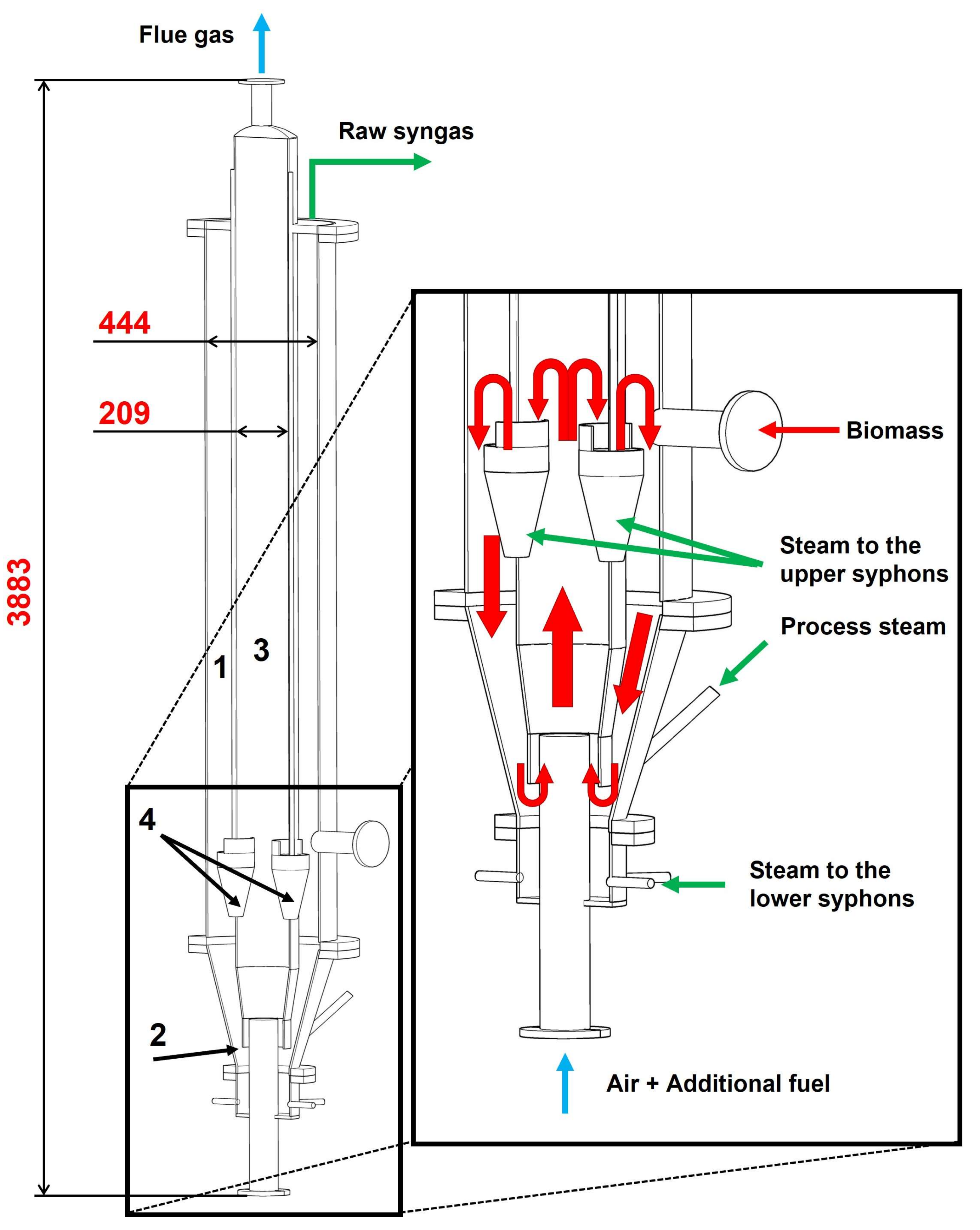
2.1. HBF 2.0 Gasifier Concept

The new reactor concept consists of two concentric fluidized beds of olivine sand particles, arranged inside a single vessel (see Figure 1):
  • The gasification zone (external cylinder) fluidized by steam.
  • The combustion zone (internal cylinder) fluidized by air.
The two chambers are connected with orifices at a given vertical distance to allow bed material circulation. The circulation system considered here is based on the application of the physical concept originally studied experimentally by Kuramoto et al. [9].
The two fluidized beds operate at different temperatures and superficial velocities (us):
i.
The fast fluidized bed (combustor) at T∼1173 K and us = 5–10 umf.
ii.
The slow fluidized bed (gasifier) at T∼1073 K and us = 2–3 umf.
The biomass is fed in the slow fluidized bed (gasifier).
The different fluidization conditions imply different bed densities (i.e., pressure gradients) and a solid circulation between the two fluidized beds. As a result, heat is exchanged between the combustor and the gasifier, due to the circulation of bed material established within the device: (i) olivine sand and residual char in the slow fluidized bed (gasifier) flow into the fast bed through the lower orifice and (ii) hot sand is recycled back into the slow fluidized bed through the upper orifice. Combustion of char and additional fuel taking place in the fast fluidized bed supplies the heat to be transported to the gasification chamber. To avoid flue gas leakages, loop seals fluidized with steam are included in the reactor design (see Figure 1).
The main novelties of this design are:
  • The system compactness, which makes it suitable for small-scale applications (0.1–1 MW as biomass input), due to integration of both reaction chambers (gasification and combustion) in the same cylindrical body;
  • The heat exchange between the two chambers occurs through bed material circulation and additionally by conduction/convection through the lateral wall of the internal cylinder;
  • The higher temperature chamber (combustor), operating at 1173–1223 K, is thermally well insulated; this reduces the drawback of thermal losses in small scale applications;
  • Longer residence time in the combustor (bubbling bed) improves the combustion efficiency of char particles.
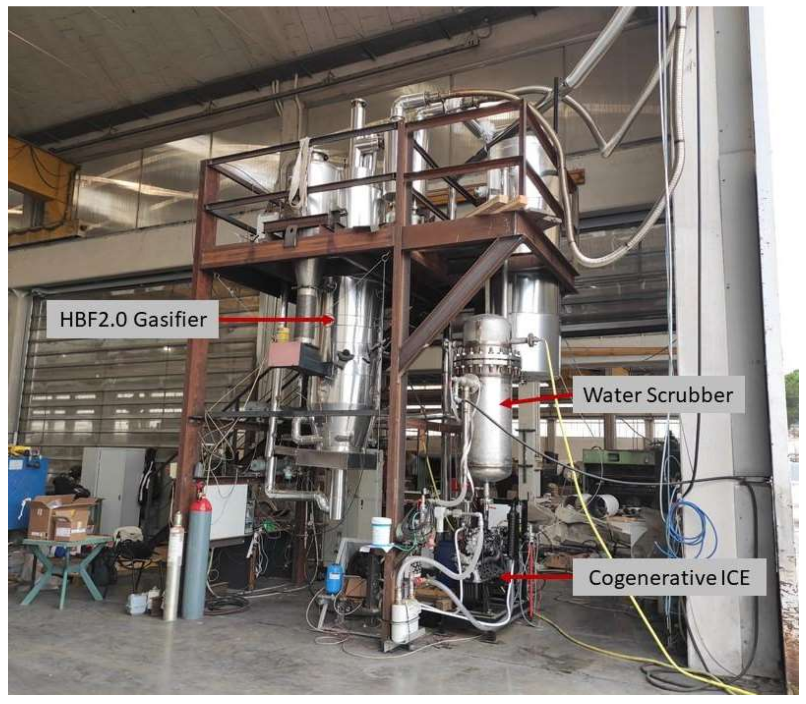
The main difference between this new concept and the well-known dual fluidized bed gasifier concepts such as that developed by Battelle Columbus [12], or the Fast Internal Circulating Fluidized Bed developed by Hofbauer et al. [8], is that in this case the two reactors are both bubbling bed (for the reason explained above) and they are arranged in a single vessel with the aim to reduce the thermal losses that occur in the small-scale applications.

2.2. Pilot Plant

The experience with the cold flow model [10] was used to realize the 100 kWth gasification pilot plant. The preliminary test and results reported in this work were obtained with a state-of-art configuration of the gasification installation, composed mainly of the gasifier, a cyclone for abatement of particulate content of the product gas, and a water scrubber for tar removal. The so-purified gaseous fuel is available for heat and power cogeneration by means of an internal combustion engine. The flowsheet and a picture of the pilot plant are shown in Figure 2 and Figure 3, respectively.
The biomass feeding system is composed of a hopper and a two screws conveyor. Air is fed to the combustor by a blower and during the start-up phase it is also fed to the gasification zone. The incoming air is pre-heated to 200 °C by means of an electric heater before entering the reactors. Steam is produced by an LPG steam generator and overheated up to 200 °C by an electrical heater. The raw gas from the gasifier passes through a cyclone, to reduce the particulate content, and then is fed to one of the following two lines. Through the former stream, the gas goes directly to the flare for complete combustion, before being evacuated to the chimney. In the latter stream, the gas passes through a water scrubber equipped with a bundle of heat exchange tubes to help the residual steam condensation in order to remove most of the tars and water. A liquid ring vacuum pump is used to suck the entire gas flow from this stream. The volumetric flow of the cold gas exiting the liquid ring pump is finally measured and then the gas is sent to the flare. This line is used for a limited period, after steady state operation of the gasifier is established, to measure the fuel gas yield. The flue gas from the combustor is depulverized in an additional cyclone and then sent to the chimney.
A slipstream of the fuel gas, approximately 1% of the total flow (0.18 Nm3/h), is sampled for the analysis of syngas composition and tar content. The slipstream is sucked through a porous element to separate the solid particles, and then it flows through a series of impingement bottles filled with 2-propanol to collect tar, according to the technical specification dictated by protocol CEN/TS 15439. The collected tar samples are analysed offline with a Gas Chromatograph with Mass Spectrometer (GC-MS) in order to identify and quantify tar compounds, and to calculate the tar content in the syngas. The tar concentration is calculated as the ratio between the mass of tar sampled to the total volume of dry gas that passes throw the impingement bottles. The clean, dry gas downstream from the impingement bottles is finally analysed by means of an online ABB analyser for the measurement of H2, CO, CO2, and CH4 volume fractions. Gas bags are also collected for the offline GC measurement of H2S, lighter hydrocarbons, and other permanent gases (i.e., N2). Two of these sampling systems are present in the plant, one just downstream from the gasifier and another downstream from the water scrubber, in order to analyse both the raw syngas and the syngas after the conditioning system.
In the start-up procedure, the gasifier (and the combustor) fluidized bed is heated up by means of the incoming hot air (200 °C) and a 20 kW start-up LPG burner placed at the gasifier bed surface. When the bed temperature reaches approximately 300 °C, biomass feeding is started, together with its combustion in the gasification zone, until the desired gasification temperature is reached. The whole warm-up procedure lasts about 4 h.
An LPG injection system was also installed into the combustor, to allow changing the temperature level of the system without varying other operating parameters. With this installation, parametric studies can be carried out easily.
Temperatures, pressures at different points of the pilot plant, and the composition of the product gas were measured and recorded continuously.

3. Results and Discussion

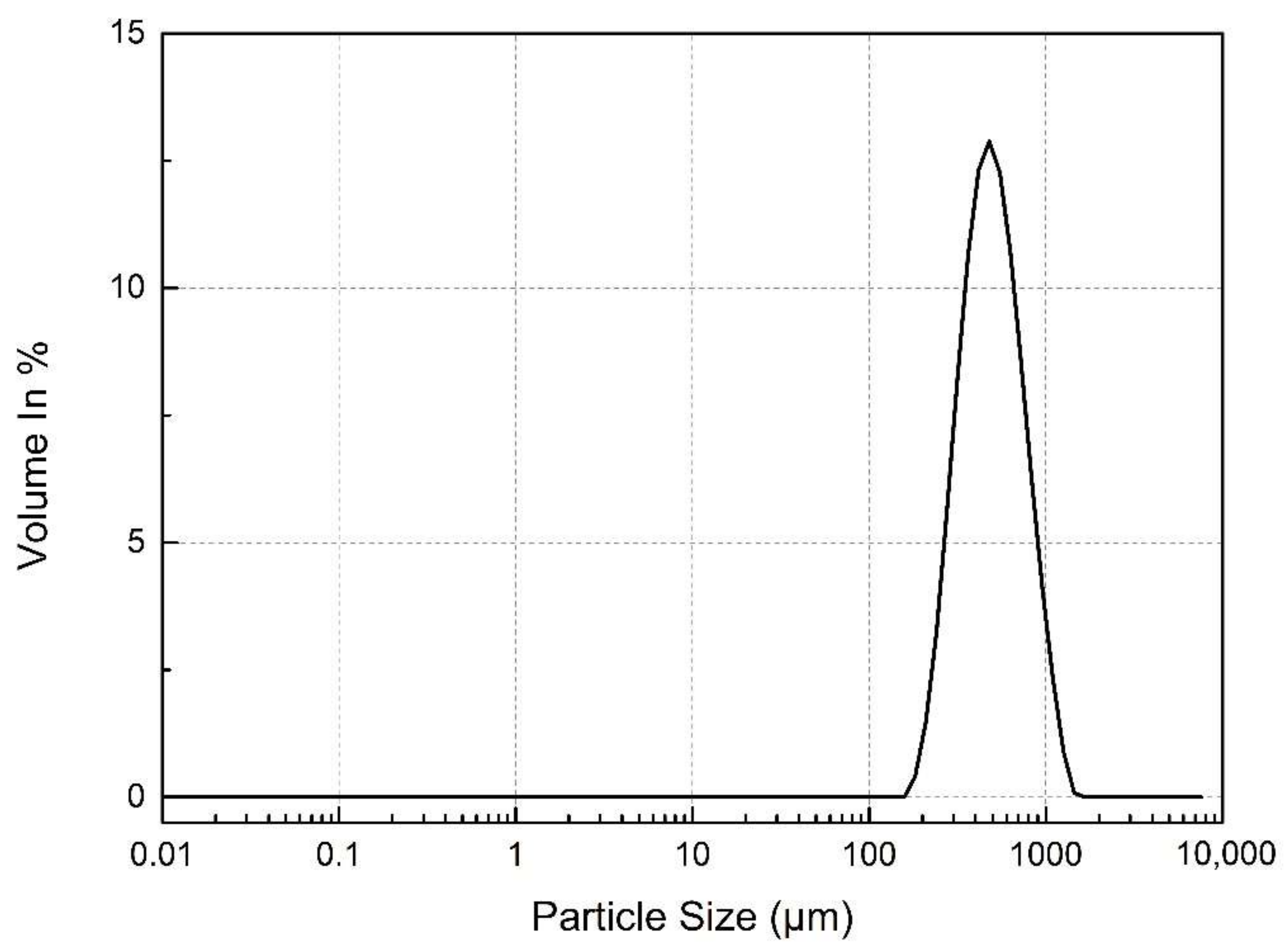
3.1. Analysis of Materials

The bed material is composed of 90 kg of olivine sand supplied by Nuova Cives Srl with a particle average diameter d3,2 = 557 µm. The particle size distribution (PSD) of the fresh batch of olivine inserted in the reactor was obtained by a Malvern Mastersizer 2000 laser diffraction particle size analyser. This PSD is shown in Figure 4.
The Sauter mean diameter of particles, defined as the diameter of a hypothetical particle having the same averaged specific surface area per unit volume as that of the given sample, was calculated by the following equation:
d 3 , 2 = 1 i = 1 n x i d i
x i is the volume fraction of particles with an average diameter equal to d i . Both x i and d i are known from the particle size distribution.
The biomass used for the tests was hazelnut shells. The proximate and ultimate analysis is shown in Table 1.
Table 2 shows a list of the protocols adopted for the analyses of Table 1.

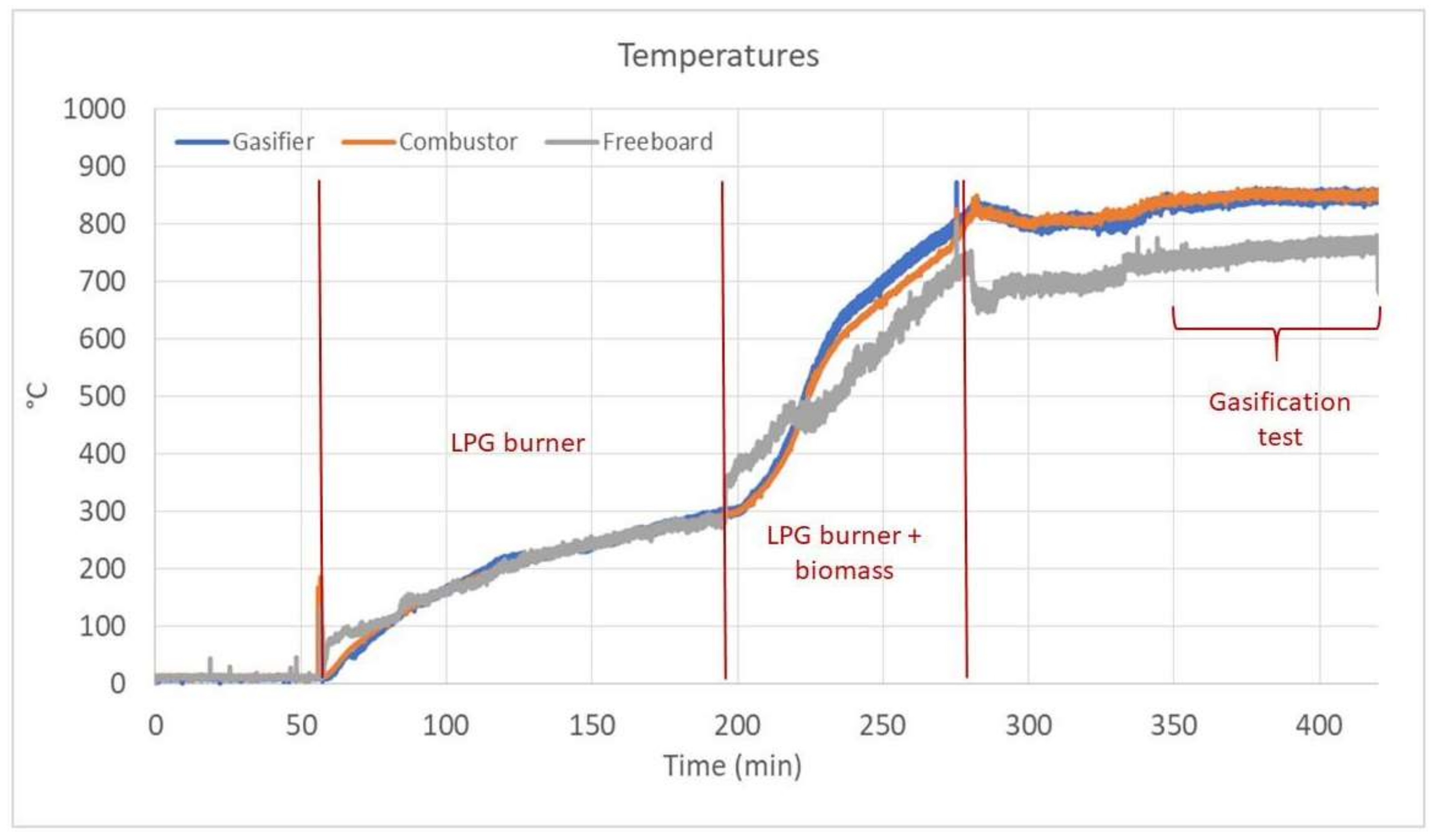
3.2. Gasification Tests

Figure 5 shows the temperatures measured during a typical start-up phase and test.
As previously mentioned, the heating up of the reactor is carried out with a flow rate of pre-heated air injected to both chambers and by means of a 20 kW LPG burner facing the gasifier bed surface; the corresponding temperature profiles are reported in Figure 5 between minute 60 and 200, when the gasifier, combustor and freeboard temperatures increase simultaneously up to 300 °C. In this phase, the heating rate is approximately 2 °C/min.
Once the temperature level of 300 °C was reached, biomass is also added to the gasifier, in order to contribute to the temperature increase by combustion. Biomass is fed at a flow rate of 10 kg/h, corresponding to about 50 kW of thermal power input. This phase is reported in Figure 5, between minute 200 and 280, when it is possible to observe a considerably higher slope of the temperature increase versus time, compared to the previous phase. In this phase, the heating rate is about 6.5 °C/min. While the temperature in the reactor increases, the air flow rate to the gasifier is gradually decreased, in order to reduce the production rate of heat required for the reactor pre-heating, however, still keeping the bed in bubbling fluidization regime.
When the temperature of approximately 830 °C is reached, the LPG burner in the gasifier is turned off, the biomass flow is stopped, and the input gas to the gasifier is switched from air to steam, keeping the air input flow to the combustion chamber. Both flow rates are set according to the operating conditions chosen for the test. After a few minutes for the stabilization of the steam flow, the biomass is introduced again in the gasifier at the desired mass flow rate and the gasification test is started.
A steady flow of LPG is also introduced in the combustion reactor chamber as auxiliary fuel, in addition to the recirculated char, in order to produce the whole heat flow necessary to sustain the endothermic gasification reactions.
Figure 5 shows that, during the gasification test starting approximately at minute 350, the temperatures are approximately constant, meaning that the flow of auxiliary fuel (LPG) and the recirculated char in the combustor are enough to supply the heat necessary for the endothermic gasification reactions. The stable temperature regime in the reactor assures that, with these process parameters, the gasification is auto-thermal.
Furthermore, the average temperature in the upper part of the freeboard is about 750 °C, which is only 100 °C lower than the temperature measured in the gasifier bed; this confirms that the thermal insulation around the reactor vessel is efficient. As shown in Figure 5, the freeboard temperature seems to keep increasing slightly during the gasification test; it is foreseen that a higher temperature in the freeboard could be reached in a longer test run. This could improve further the quality of the syngas by enhancing the conversion of tars in the freeboard.
Biomass gasification tests were carried out with the input conditions reported in Table 3.
The raw product gas composition in terms of H2, CO, CO2, and CH4 volume fractions was measured online during the test. Detected values are reported in Figure 6 for a typical gasification test.
Figure 6 shows that the gas composition is approximately constant during the 75 min of the test, meaning that the gasification process reached the steady state. H2 content in the fuel gas is around 35%.
The results of the gasification tests were evaluated also in terms of some performance parameters, such as:
  • The dry gas yield, ηgas, calculated as:
η gas =   Q ˙ syngas , dry   m ˙ bio   Nm 3 kg bio
  • The CGE % (Cold Gas Efficiency), calculated as:
    CGE   % =   Q ˙ dry , syngas   LHV syngas   m ˙ bio LHV bio +   m ˙ LPG LHV LPG 100
  • The carbon conversion, calculated as:
    C   conversion   % = i = CO ,   CO 2 ,   CH 4 , mol i mol C   bio
The main outputs of the gasification tests carried out in different days are summarised in Table 4.
The data reported in Table 4 show that the volume fraction of N2 in the syngas is maximum 10%, so it can be deduced that the gas leakage from the combustor to the gasifier is minimum, and the separation of the gas streams between the two chambers is efficient. The relatively high value of the syngas LHV confirms this result.
The sum of the gas volume fractions detected is 95.6%, meaning that only approximately 4% of the gas composition is unknown, probably consisting of light hydrocarbons (C2–C6). These results are comparable with those obtained with similar gasification technologies as described in the work of Larsson et al. [13]. In fact, depending on the gasification technologies. the data points from operation with woody biomass and olivine for six gasifiers (GoBiGas, Senden, Chalmers, Gussing, Oberwart, Villach) show that the hydrogen concentration varies between 30 to 45%, the CO between 15 to 30%, the CO2 between 20 to 30%, and the CH4 between 5 to 12%.
There are relevant differences instead comparing the results of this work with those of the Milena gasifier [14]. The CH4 and CO content in the syngas of the Milena gasifier is slightly higher (12% and 29%), while H2 is lower (25%). These differences can be explained by the low S/B ratio used in the test of the Milena gasifier (0.28): the carbon is only partially gasified at such a low S/B ratio.
The measurement of the syngas flow rate allowed to calculate the ηgas obtained in the test, 1.33 Nm3/kg, which is very similar to the values obtained in non-catalytic biomass gasification tests on laboratory scale [15].
The H2S content measured in the syngas is of the order of 100 ppm, which is in the same order of magnitude of the values reported in literature for woody biomass [16,17].
The analysis of the tar samples collected downstream from the gasifier during the test gave as a result 12.4 g/Nm3 on dry basis, coherently with the level of 10 g/Nm3 generally expected for fluidized bed gasifiers [18,19]. Tar content of the raw syngas is too high for direct use in downstream systems for the production of energy; however, tars can be significantly reduced with conditioning systems.

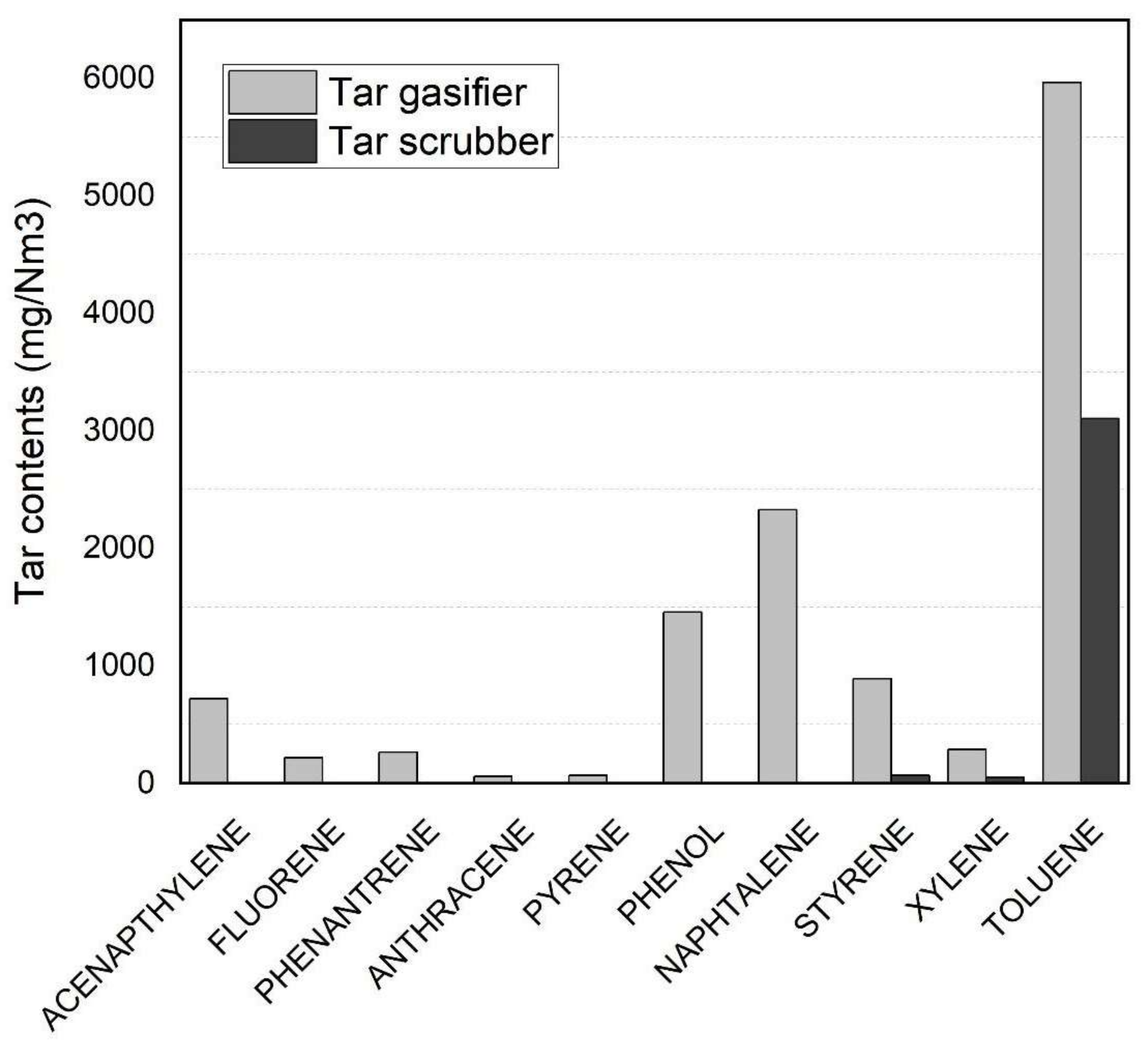
3.3. Gas Conditioning Systems

A water scrubber was used as the conditioning system for the product gas.
Inside the scrubber, the temperature of the gas is strongly reduced thanks to fresh water flowing in the bundle of tubes; in this way, the humidity content in the gas condensates and generates water droplets that remove tar from the syngas stream.
The tar content at the outlet of the gasifier, obtained in the test described in the previous section, was compared with the tar content obtained downstream the water scrubber. The comparison of tar contents is reported in Figure 7.
It is possible to observe that the conditioning system led to a considerable reduction in tar content, compared to values measured at the exit of the gasifier (12.4 g/Nm3). The syngas sampled downstream of the water scrubber showed a tar content of 3.2 g/Nm3, resulting in an efficiency of more than 74% of the scrubber in tar removal. The residual tars are mainly toluene, which is a lighter hydrocarbon; the residual tar composition is compatible with the use of the syngas in the internal combustion engine (ICE). In fact, as reported in [18], some of the “light tars” (such as benzene and toluene) are not considered as harmful components in the gas, since these compounds are found in important quantities in gasoline.

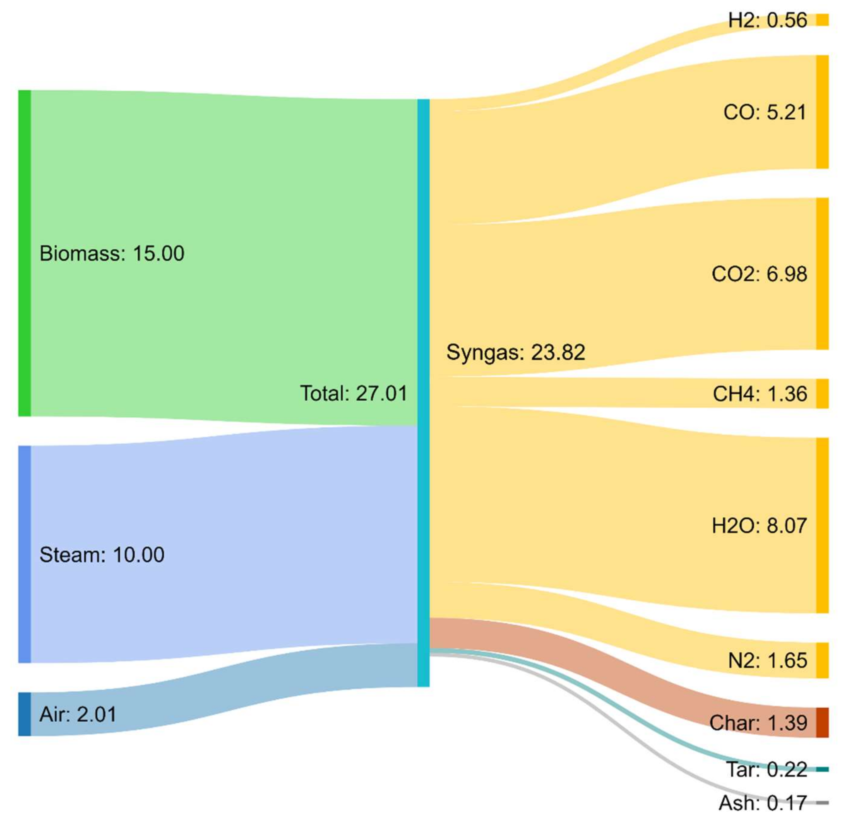
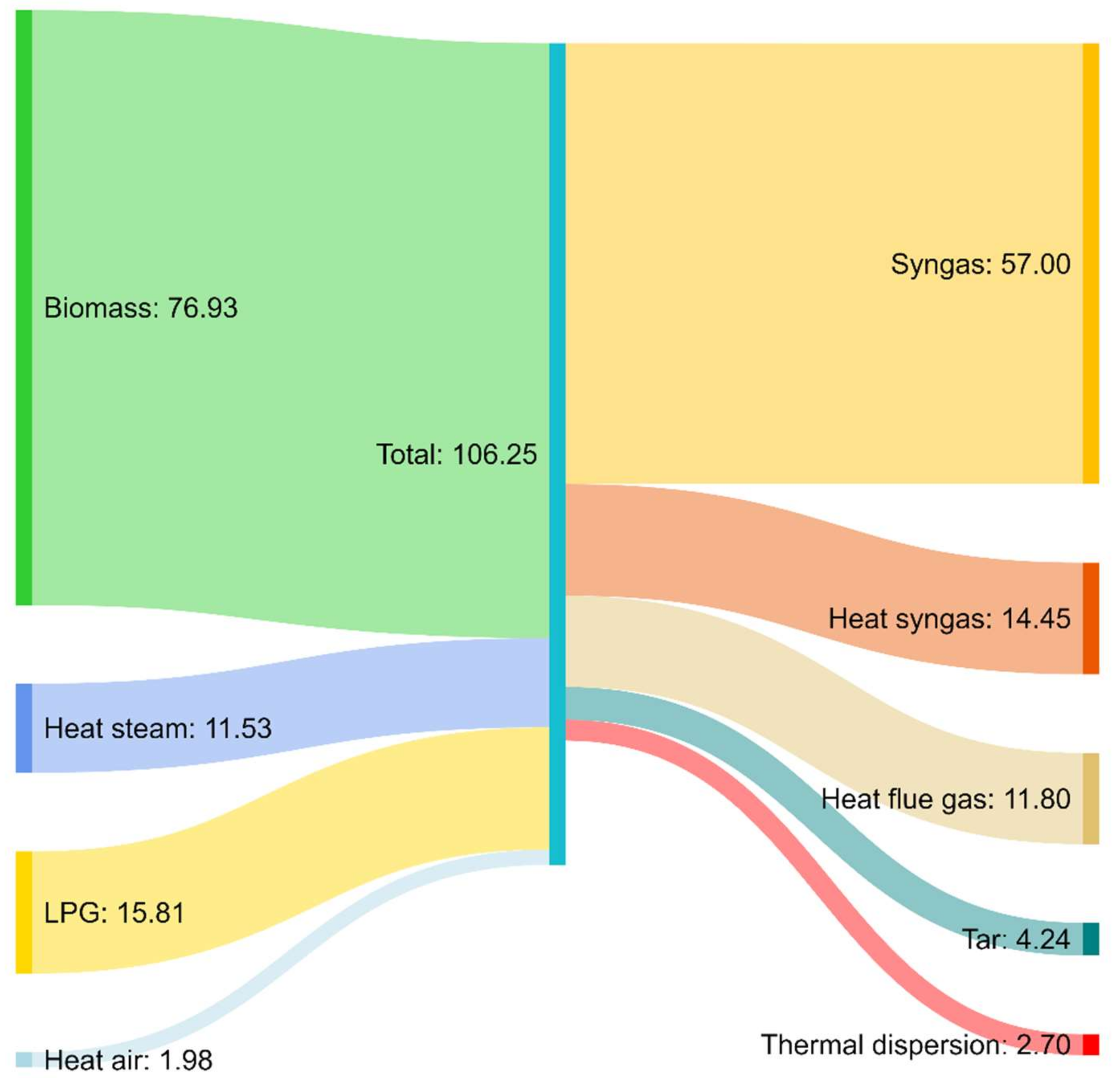
3.4. Mass and Energy Balances

In order to check the reliability of the results obtained, the mass and energy balances were calculated for the gasification test. The ash produced was estimated based on the biomass analysis reported in Table 1. The char produced, which is circulated from the gasifier to the combustor, was assumed as 10% of the input biomass, as reported in [8]. The H2O conversion was estimated around 30% based on the experimental findings reported in [8]. It was assumed that the nitrogen in the syngas is due to air leakage from the combustor. The flow rate of air was estimated from the knowledge of nitrogen found in the syngas.
The results of mass balance on the gasification chamber and energy balance on the whole dual-bed reactor are reported in Figure 8 and Figure 9, respectively.
Figure 8 shows that the mass balance on the gasifier is closed with a very small error (around 4%), with the above assumptions dictated by previous experimental evidence [8]. This error can be further reduced if the light hydrocarbons would be also considered in the mass balance. These light hydrocarbons are certainly in the syngas, with a concentration between 2 to 5%, as reported in the work of Larsson et al. [13]. It is possible to observe that humid syngas represents the most abundant of the outputs, accounting for 93% of the total products. Tar and ash account for less than 1% of the total products; char is 5.5% of the total output of the gasifier and it is assumed as a mass and energy input for the combustion reactor.
For the energy balance, except for the energy contents of biomass, LPG, syngas, and tar, the energies/time required for pre-heating the input flows (air and steam) and the residual heat content of the output flows were considered. In particular, air and steam were introduced in the gasifier at approximately 200 °C; the syngas exits the gasifier at around 800 °C, as measured in the freeboard, and the flue gas exits the combustion chamber at 850 °C. For the energy balance, the higher heating values (HHV) were considered, and the residual heat of the output streams were calculated, reporting the products to 25 °C.
Figure 9 shows the energy balance calculated on the whole dual-bed gasification reactor, which closes with an error of about 14%. In addition, in this case the error can be reduced if the light hydrocarbons would be taken into account in the energy balance. In fact, adding C2H4 [13] in the energy balance, and considering that its concentration, on a dry basis, can vary between 2 to 5%, the error would be reduced to less than 1%. The chemical energy of the syngas flow represents 63% of the total output.
The thermal dispersion of the reactor was calculated based on the temperature measured on the external surface of the reactor during the operation, equal to 70 °C; the convective heat transfer coefficient of air was considered as 5 W/m2 K.
The sensible heat in the flow rate of syngas and that of flue gas account for approximately 16% and 12% of the total energy outputs, respectively. These energy outputs could be recovered internally in the process in practical applications, for instance used in heat exchangers for pre-heating the input air, evaporating water, and superheating steam to the gasifier. This heat recovery would allow to increase the temperatures of the input streams to the gasifier from 200 °C to 450 °C, and therefore to reduce the auxiliary fuel flow rate needed for the thermal requirements of the process, from about 15 kW in the test described here to about 11 kW.

4. Conclusions

In a previous work [10], an innovative design of a dual bubbling fluidized bed gasifier was developed, and cold model experiments were carried out to check the performance of the reactor geometry from a fluid-dynamic point of view. Subsequently, the reactor was realized at pilot scale (up to 100 kWth as thermal input), and in this work the results of the preliminary gasification tests are reported.
Temperature monitoring during the start-up phase shows that it is possible to reach the desired operating temperature in approximately 4 h, by heating the reactor by means of LPG and biomass combustion.
Gasification tests were carried out using hazelnut shells as biomass feedstock, feeding steam to the gasifier and air to the combustor. The heat produced in the combustor by burning the residual char and the auxiliary LPG fuel was found to be enough for the gasification process, as confirmed by the stability of the temperature values measured during the test.
The syngas composition analysed online also showed fair stability during a typical test that lasted approximately 70 min. The average volumetric composition of the syngas was: H2 = 35%, CO = 23%, CO2 = 20%, and CH4 = 11%. The N2 content in the gas was as low as 7%, which confirms the efficient design of the gasifier as far as the separation of the gas flows in the two chambers is concerned. Mass and energy balances, closed with a small error, add reliability to the results obtained.
The tar content of the raw syngas, obtained in the plain biomass gasification test, was 12 g/Nm3. In order to reduce the tar content, a water scrubber downstream from the gasifier was used as the conditioning system. The water scrubber showed good efficiency in reducing the tar content from the syngas stream, with a residual tar content of about 3 g/Nm3.
Future test campaigns are planned on the pilot plant, also changing the main process parameters. Further tests will allow to identify the best operating conditions to obtain a high-quality syngas with low content of pollutants.
Furthermore, new tests are planned to evaluate the behaviour of the gasifier using different biomass feedstocks: in particular, olive pits, olive pomace, and in the future also wood chips and wood pellets. For these tests, a new calibration of the two screw conveyors will be necessary to evaluate the exact flow rate of the biomass fed, with the density of the feedstocks being different than the one used in this work. Attention will also be given to the velocity of the second screw conveyor (the fast one) to reduce the residence time of the fuel and thus avoid the fuel starting to pyrolyze before entering the reactor. Injections of CO2 or N2 in the screw feeder and in the hopper will be considered to help with this problem.

5. Patents

The patent 102022000007613 that describe the gasification unit has been submitted to the Italian Patent Office.

Author Contributions

Conceptualization, A.D.C., E.S., P.U.F. and E.B.; methodology, A.D.C., E.S., A.A.P. and A.T.; investigation, A.D.C., E.S., A.A.P., A.T., L.D.Z. and E.B.; data curation, A.D.C. and E.S.; writing—original draft preparation, A.D.C. and E.S.; writing—review and editing, A.D.C., E.S., P.U.F., L.D.Z., A.A.P., A.T., B.A. and E.B.; supervision E.B. and P.U.F. All authors have read and agreed to the published version of the manuscript.

Funding

This research was funded by the Italian Ministry of Economic Development, under the research project HBF 2.0, proposal number: CCSEB_00224.

Acknowledgments

The authors affiliated kindly acknowledge the financial support of R&D Project HBF 2.0, funded by the Italian Ministry of Economic Development.

Conflicts of Interest

The authors declare no conflict of interest.

Nomenclature

u s Superficial velocity (m/s)
u mf Minimum fluidization velocity (m/s)
η gas Gas yield (Nm3/kg)
  Q ˙ syngas , dry Volumetric flow of dry syngas (Nm3/h)
  m ˙ bio Input biomass flow (kg/h)
CGE Cold Gas Efficiency (%)
  Q ˙ syngas Syngas total volumetric flow (Nm3/h)
LHV syngas Syngas lower heating value (MJ/Nm3)
LHV bio Biomass lower heating value (MJ/kg)
  m ˙ LPG LPG mass flow (kg/h)
LHV LPG LPG lower heating value (MJ/kg)
mol C   bio Total moles of C in the input biomass (mol)
TAverage temperature (°C)

References

  1. Nikoo, M.B.; Mahinpey, N. Simulation of biomass gasification in fluidized bed reactor using ASPEN PLUS. Biomass Bioenergy 2008, 32, 1245–1254. [Google Scholar] [CrossRef]
  2. Li, X.; Grace, J.; Lim, C.; Watkinson, A.; Chen, H.; Kim, J. Biomass gasification in a circulating fluidized bed. Biomass- Bioenergy 2004, 26, 171–193. [Google Scholar] [CrossRef]
  3. Hofbauer, H.; Rauch, R.; Loeffler, G.; Kaiser, S.; Fercher, E.; Tremmel, H. Six years experience with the FICFB-gasification process. In Proceedings of the 12th European Conference and Technology Exhibition on Biomass for Energy, Industry and Climate Protection, Amsterdam, The Netherlands, 17–21 June 2002. [Google Scholar]
  4. Igarashi, M.; Hayafune, Y.; Sugamiya, R.; Nakagawa, Y.; Makishima, K. Pyrolysis of Municipal Solid Waste in Japan. J. Energy Resour. Technol. 1984, 106, 377. [Google Scholar] [CrossRef]
  5. Van der Drift, A.; Van der Meijden, C.M.; Boerrigter, H. MILENA gasification technology for high efficient SNG production from biomass. In Proceedings of the 14th European Conference and Technology Exhibition on Biomass for Energy, Industry and Climate Protection, Paris, France, 17–21 October 2005. [Google Scholar]
  6. Matsuoka, K.; Kuramoto, K.; Murakami, T.; Suzuki, Y. Steam Gasification of Woody Biomass in a Circulating Dual Bubbling Fluidized Bed System. Energy Fuels 2008, 22, 1980–1985. [Google Scholar] [CrossRef]
  7. Corella, J.; Toledo, A.J.M.; Molina, G. A Review on Dual Fluidized-Bed Biomass Gasifiers. Ind. Eng. Chem. Res. 2007, 46, 6831–6839. [Google Scholar] [CrossRef]
  8. Hofbauer, H.; Fercher, E.; Fleck, T.; Rauch, R.; Veronik, G. Two years experience with the FICFB-gasification process. In Proceedings of the 10th European Conference and Technology Exhibition on “Biomass for Energy And Industry”, Wurzburg, Germany, 8–11 June 1998. [Google Scholar]
  9. Kuramoto, M.; Kunii, D.; Furusawa, T. Flow of dense fluidized particles through an opening in a circulation system. Powder Technol. 1986, 47, 141–149. [Google Scholar] [CrossRef]
  10. Di Carlo, A.; Moroni, M.; Savuto, E.; Pallozzi, V.; Bocci, E.; Di Lillo, P. Cold model testing of an innovative dual bubbling fluidized bed steam gasifier. Chem. Eng. J. 2019, 377, 119689. [Google Scholar] [CrossRef]
  11. HBF High Performance Flexible Small Scale Biomass Gasifier 2.0. Project Funded by the Italian Ministry of Economic Development. 2017. Available online: https://www.hbf2-0.it/ (accessed on 20 May 2022).
  12. Spath, P.; Aden, A.; Eggeman, T.; Ringer, M.; Wallace, B.; Jechura, J. Biomass to Hydrogen Production Detailed Design and Economics Utilizing the Battelle Columbus Laboratory Indirectly-Heated Gasifier. 2005. Available online: http://www.osti.gov/bridge (accessed on 20 May 2022).
  13. Larsson, A.; Kuba, M.; Vilches, T.B.; Seemann, M.; Hofbauer, H.; Thunman, H. Steam gasification of biomass—Typical gas quality and operational strategies derived from industrial-scale plants. Fuel Process. Technol. 2021, 212, 106609. [Google Scholar] [CrossRef]
  14. Van Der Meijden, C.M.; Van Der Drift, A.; Vreugdenhil, B.J. Experimental results from the allothermal biomass gasifier Milena Experimental results from the allothermal biomass gasifier Milena Experimental Results From The Allothermal Biomass Gasifier Milena. In Proceedings of the 15th European Biomass Conference, Berlin, Germany, 7–11 May 2007; Available online: https://www.researchgate.net/publication/264092142 (accessed on 20 May 2022).
  15. Savuto, E.; Di Carlo, A.; Steele, A.; Heidenreich, S.; Gallucci, K.; Rapagnà, S. Syngas conditioning by ceramic filter candles filled with catalyst pellets and placed inside the freeboard of a fluidized bed steam gasifier. Fuel Process. Technol. 2019, 191, 44–53. [Google Scholar] [CrossRef]
  16. Abdoulmoumine, N.; Adhikari, S.; Kulkarni, A.; Chattanathan, S. A review on biomass gasification syngas cleanup. Appl. Energy 2015, 155, 294–307. [Google Scholar] [CrossRef]
  17. Cui, H.; Turn, S.Q.; Keffer, V.; Evans, D.; Tran, T.; Foley, M. Study on the fate of metal elements from biomass in a bench-scale fluidized bed gasifier. Fuel 2013, 108, 1–12. [Google Scholar] [CrossRef]
  18. Milne, T.A.; Evans, R.J.; Abatzoglou, N. Biomass Gasifier “Tars”: Their Nature, Formation, and Conversion; National Renewable Energy Laboratory: Golden, CO, USA, 1998. [Google Scholar] [CrossRef] [Green Version]
  19. Basu, P. Biomass Gasification and Pyrolysis; Elsevier Inc.: Amsterdam, The Netherlands, 2010. [Google Scholar]
Figure 1. A 3D sketch of the new dual bubbling fluidized bed gasifier: (1) gasification chamber; (2) lower siphon; (3) combustion chamber; (4) upper siphon.
Energies 15 04369 g001
Figure 2. Flowsheet of the gasification pilot plant.
Energies 15 04369 g002
Figure 3. Picture of pilot plant.
Energies 15 04369 g003
Figure 4. Particle size distribution of olivine.
Energies 15 04369 g004
Figure 5. Temperature values measured during the start-up phase and during the gasification test.
Energies 15 04369 g005
Figure 6. Raw fuel gas composition measured online during gasification test period.
Energies 15 04369 g006
Figure 7. Tar contents measured in the raw syngas and downstream from the water scrubber.
Energies 15 04369 g007
Figure 8. Gasifier mass balance (units in kg/h).
Energies 15 04369 g008
Figure 9. Dual-bed reactor energy balance (units in kW).
Energies 15 04369 g009
Table 1. Proximate and ultimate analyses of hazelnut shells (moisture content = 8.00%.).
Ash (wt%db)1.2
Volatile matter (wt%db)75.5
Fixed Carbon (wt%db)23.2
C (wt%db)50.96
H (wt%db)5.72
N (wt%db)0.42
S (wt%db)0.03
O (wt%db)41.60
HHV (MJ/kg)db19.93
LHV (MJ/kg)db18.12
Table 2. Methods of reference for the characterizations of the hazelnut shells.
CharacterizationParameterRef. Method
HumidityAmount of water in the as-received sampleUNI EN 14774-1
(ASTM E203)
Proximate AnalysisAsh ContentUNI EN 14775-TAPPI Standard T 211 om-93
Volatile Matter (VM)
Fixed Carbon (FC)
UNI EN 15148, mod. ASTM modif. D3175
Ultimate AnalysisElemental analysis (C, H, N, O)UNI EN 15104
Sulphur (S), Chlorine (Cl)UNI EN 15289
Calorific valueHigher Heating Value (HHV)
Lower Heating Value (LHV)
UNI EN 14918, ISO 1928 DIN 51900–TAPPI Test T684
Table 3. Input conditions for gasification test.
Biomass feeding rate (kg/h)15
Steam—central (kg/h)10
Steam—lower orifice (kg/h)2.5
Steam—upper orifice (kg/h)1.5
Air combustor (kg/h)39
LPG combustor (L/min)10
Table 4. Results of the gasification test.
T gasifier (°C)810–846
T combustor (°C)810–872
Duration (min)75
ηgas (Nm3/kg)1.33 ± 0.11
H2 (%vol dry)34.8 ± 1.0
CO (%vol dry)23.2 ± 1.2
CO2 (%vol dry)19.7 ± 1.2
CH4 (%vol dry)10.6 ± 0.7
N2 (%vol dry)7.3 ± 2.3
H2S (ppm dry)55–120
Tar content (g/Nm3)12.4 ± 6.0
LHV (MJ/Nm3)10.5 ± 0.4
CGE (%)65.8 ± 1.2
C conversion (%)72.8± 2.5
Publisher’s Note: MDPI stays neutral with regard to jurisdictional claims in published maps and institutional affiliations.

