
Review of the Liquid Hydrogen Storage Tank and Insulation System for the High-Power Locomotive


Abstract
1. Introduction
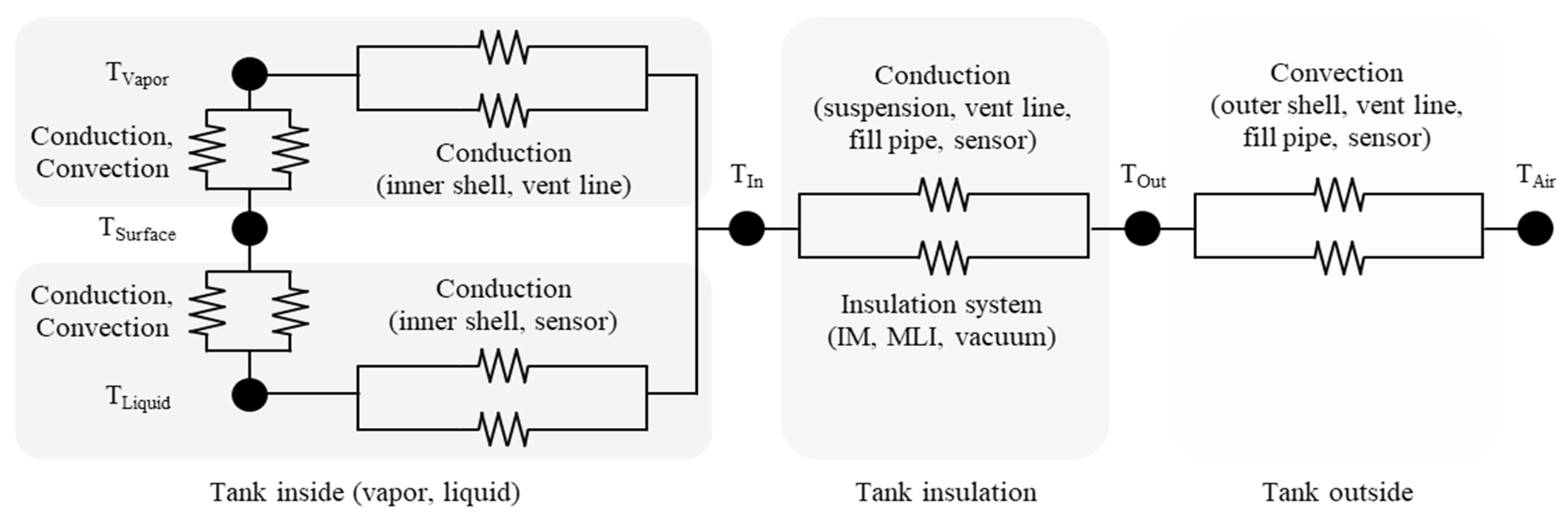
2. Static Modeling
2.1. Wall, Vacuum Gap, Suspension, and Sensors
2.2. Inner Materials
2.3. Multi-Layer Insulation
2.4. Phase Change of Liquid Hydrogen
3. Dynamic Modeling
3.1. Changes due to Phase Change of the Hydrogen
3.2. Vapor-Cooled Shield or Vent Line
3.3. Boil-Off Ratio
4. Systematic Modeling
4.1. Capacity of the Power Required and the Fuel Tank
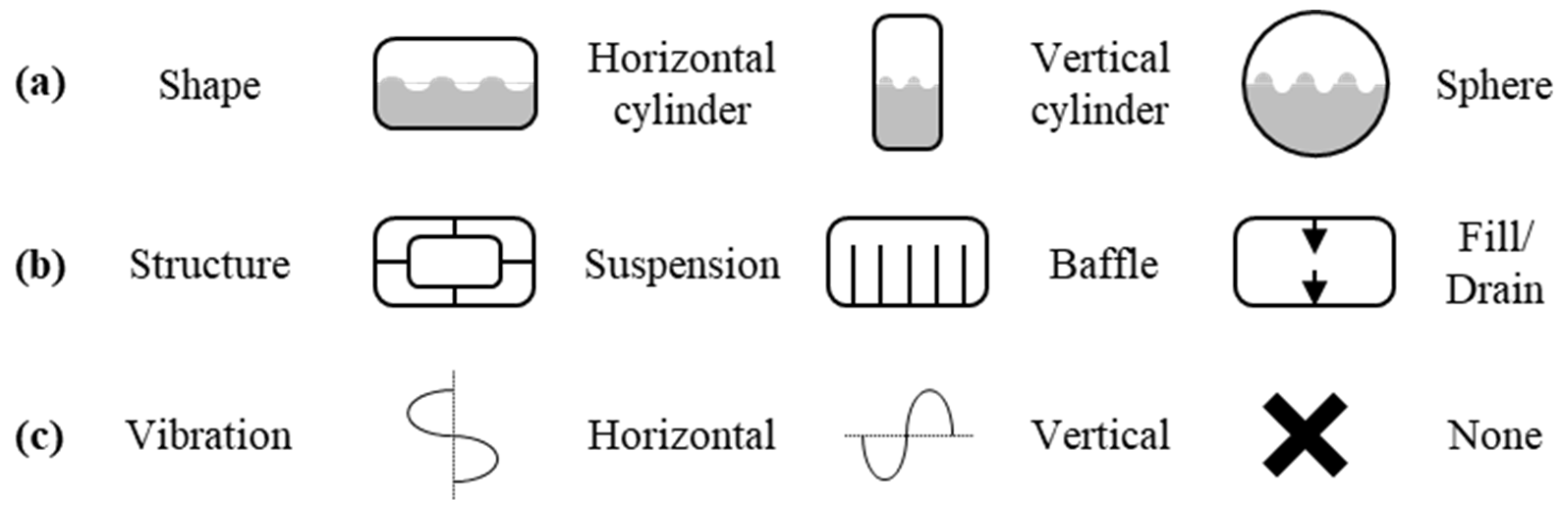
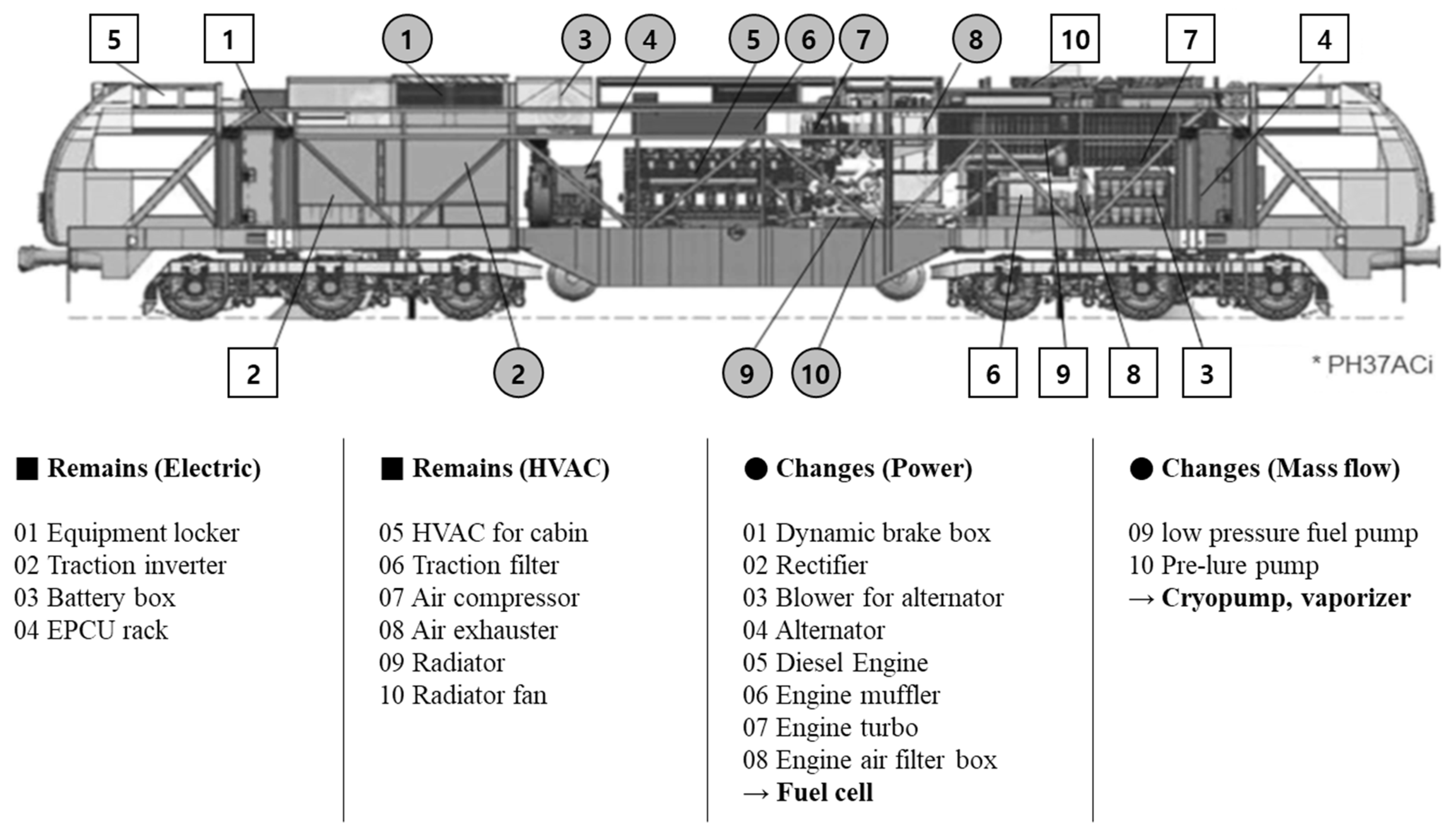
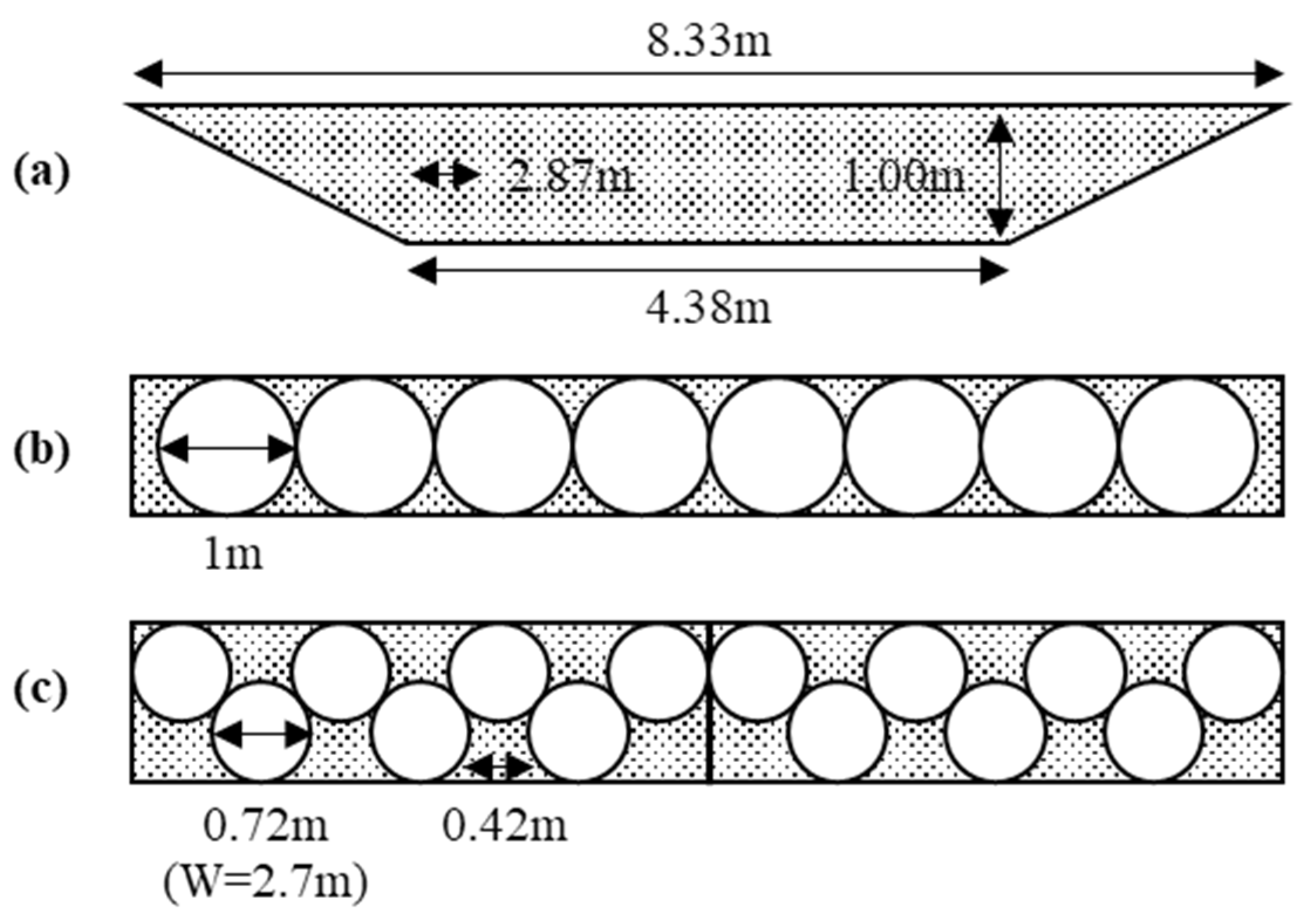
4.2. Arrangement of the Fuel Tank
4.3. Structure and Efficiency of the Fuel Tank
5. Future Research Needs
- (1)
- The optimal suspension design between vessels and baffles in the inner vessel can be studied to minimize the BOG. Various CFD can be studied depending on the structure and vibration direction.
- (2)
- The optimal location and method of filling and drain can be studied. Depending on the circumstances, the BOG in the charging process can be larger than the BOG in storage.
- (3)
- Materials and arrangement of the vessel wall and insulation system can be studied. Former studies only focused on the insulation effect, but the optimal arrangement can exist depending on the operation, including filling and draining. A 4E analysis (Energy, Economic, Enthalpy, and Entropy) can be used.
- (4)
- Dynamic control of the pressure, mass flow, and vaporizer (heat exchanger) system before the fuel cell can be studied.
- (5)
- Utilizing the heat of the fuel cell or battery for heating the hydrogen in the vaporizer can also be studied.
- (6)
- The arrangement of new components can be researched. For example, fuel cells and battery modules require a large cooling capacity. Liquid- or phase-change cooling can be applied.
- (7)
- Various LH2 vessel shapes, locations, and arrangements can be studied. The charger design is needed to research because of the large loss and BOG generation in the filling process.
6. Conclusions
Author Contributions
Funding
Institutional Review Board Statement
Informed Consent Statement
Data Availability Statement
Conflicts of Interest
References
- Wijayanta, A.T.; Oda, T.; Purnomo, C.W.; Kashiwagi, T.; Aziz, M. Liquid hydrogen, methylcyclohexane, and ammonia as potential hydrogen storage: Comparison review. Int. J. Hydrogen Energy 2019, 44, 15026–15044. [Google Scholar] [CrossRef]
- Wijayanta, A.T.; Nakaso, K.; Aoki, T.; Kitazako, Y.; Fukai, J. Effect of pressure, composition and temperature characteristics on thermal response and overall reaction rates in a metal hydride tank. Int. J. Hydrogen Energy 2011, 36, 3529–3536. [Google Scholar] [CrossRef]
- Aziz, M. Liquid Hydrogen: A Review on Liquefaction, Storage, Transportation, and Safety. Energies 2021, 14, 5917. [Google Scholar] [CrossRef]
- Hastings, L.J.; Hedayat, A.; Brown, T.M. Analytical Modeling and Test Correlation of Variable Density Multilayer Insulation for Cryogenic Storage; NASA: Washington, DC, USA, 2004.
- Hastings, L.J.; Martin, J.J. Experimental testing of a foam/multilayer insulation (FMLI) thermal control system (TCS) for use on a cryogenic upper stage. AIP Conf. Proc. 1998, 420, 331–341. [Google Scholar]
- Hedayat, A.; Hastings, L.J.; Brown, T. Analytical modeling of variable density multilayer insulation for cryogenic storage. AIP Conf. Proc. 2002, 613, 1557–1564. [Google Scholar]
- Pehr, K.; Sauermann, P.; Traeger, O.; Bracha, M. Liquid hydrogen for motor vehicles-the world’s first public LH2 filling station. Int. J. Hydrogen Energy 2001, 26, 777–782. [Google Scholar] [CrossRef]
- Qiu, Y.; Yang, H.; Tong, L.; Wang, L. Research progress of cryogenic materials for storage and transportation of liquid hydrogen. Metals 2021, 11, 1101. [Google Scholar] [CrossRef]
- Bergman, T.L.; Lavine, A.S.; Incropera, F.P.; DeWitt, D.P. Fundamentals of Heat and Mass Transfer; John Wiley & Sons: Hoboken, NJ, USA, 2011. [Google Scholar]
- Polinski, J. Materials in Cryogenics; European Course in Cryogenics; CERN: Geneva, Switzerland, 2010. [Google Scholar]
- Fesmire, J.E. Layered composite thermal insulation system for nonvacuum cryogenic applications. Cryogenics 2016, 74, 154–165. [Google Scholar] [CrossRef]
- Johnson, W.; Fesmire, J. Thermal performance of low layer density multilayer insulation using liquid nitrogen. AIP Conf. Proc. 2012, 1434, 39–46. [Google Scholar]
- Tseng, C.; Yamaguchi, M.; Ohmori, T. Thermal conductivity of polyurethane foams from room temperature to 20 K. Cryogenics 1997, 37, 305–312. [Google Scholar] [CrossRef]
- Mekonnen, B.T.; Ding, W.; Liu, H.; Guo, S.; Pang, X.; Ding, Z.; Seid, M.H. Preparation of aerogel and its application progress in coatings: A mini overview. J. Leather Sci. Eng. 2021, 3, 25. [Google Scholar] [CrossRef]
- Liu, Z.; Li, Y.; Zhou, G. Insulation performance of foam during the terrestrial and ascent period. Appl. Therm. Eng. 2018, 145, 364–374. [Google Scholar] [CrossRef]
- Wang, P.; Liao, B.; An, Z.; Yan, K.; Zhang, J. Measurement and calculation of cryogenic thermal conductivity of HGMs. Int. J. Heat Mass Transf. 2019, 129, 591–598. [Google Scholar] [CrossRef]
- Wang, P.; Ji, L.; Yuan, J.; An, Z.; Yan, K.; Zhang, J. Modeling and optimization of composite thermal insulation system with HGMs and VDMLI for liquid hydrogen on orbit storage. Int. J. Hydrogen Energy 2020, 45, 7088–7097. [Google Scholar] [CrossRef]
- Andersson, J.; Grönkvist, S. Large-scale storage of hydrogen. Int. J. Hydrogen Energy 2019, 44, 11901–11919. [Google Scholar] [CrossRef]
- Wang, P.; Ji, L.; Yuan, J.; An, Z.; Yan, K.; Zhang, J. The influence of inner material with different average thermal conductivity on the performance of whole insulation system for liquid hydrogen on orbit storage. Int. J. Hydrogen Energy 2021, 46, 10913–10923. [Google Scholar] [CrossRef]
- Kim, T.Y.; Lee, J.H. Electromagnetic Shielding Effectiveness of CFRP Panels, MLI, and RF Screens for Spacecraft Applications. J. Korean Inst. Electromagn. Eng. Sci. 2020, 31, 947–955. [Google Scholar] [CrossRef]
- Liu, Z.; Li, Y.; Xie, F.; Zhou, K. Thermal performance of foam/MLI for cryogenic liquid hydrogen tank during the ascent and on orbit period. Appl. Therm. Eng. 2016, 98, 430–439. [Google Scholar] [CrossRef]
- Hedayat, A.; Brown, T.M.; Hastings, L.J.; Martin, J. Variable density multilayer insulation for cryogenic storage. In Proceedings of the 36th AIAA/ASME/SAE/ASEE Joint Propulsion Conference and Exhibit, Las Vegas, NV, USA, 24–28 July 2000. [Google Scholar]
- Johnson, W.L. Thermal Performance of Cryogenic Multilayer Insulation at Various Layer Spacings. Master’s Thesis, University of Central Florida, Orlando, FL, USA, 2010. [Google Scholar]
- Johnson, W.L. Optimization of layer densities for multilayered insulation systems. AIP Conf. Proc. 2010, 1218, 804–811. [Google Scholar]
- Wang, B.; Huang, Y.H.; Li, P.; Sun, P.J.; Chen, Z.C.; Wu, J.Y. Optimization of variable density multilayer insulation for cryogenic application and experimental validation. Cryogenics 2016, 80, 154–163. [Google Scholar] [CrossRef]
- Zheng, J.; Chen, L.; Cui, C.; Guo, J.; Zhu, W.; Zhou, Y.; Wang, J. Experimental study on composite insulation system of spray on foam insulation and variable density multilayer insulation. Appl. Therm. Eng. 2018, 130, 161–168. [Google Scholar] [CrossRef]
- Huang, Y.; Wang, B.; Zhou, S.; Wu, J.; Lei, G.; Li, P.; Sun, P. Modeling and experimental study on combination of foam and variable density multilayer insulation for cryogen storage. Energy 2017, 123, 487–498. [Google Scholar] [CrossRef]
- Fesmire, J.E. Standardization in cryogenic insulation systems testing and performance data. Phys. Procedia 2015, 67, 1089–1097. [Google Scholar] [CrossRef]
- Kuma, S.P.; Prasad, B.V.S.S.S.; Venkatarathnam, G.; Ramamurthi, K.; Murthy, S.S. Influence of surface evaporation on stratification in liquid hydrogen tanks of different aspect ratios. Int. J. Hydrogen Energy 2007, 3, 21954–21960. [Google Scholar]
- Horie, Y.; Shirai, Y.; Shiotsu, M.; Matsuzawa, T.; Yoneda, K.; Shigeta, H.; Tatsumoto, H.; Hata, K.; Naruo, Y.; Kobayashi, H.; et al. Film boiling heat transfer properties of liquid hydrogen in natural convection. Phys. Procedia 2015, 67, 643–648. [Google Scholar] [CrossRef][Green Version]
- Baldwin, M.; Ghavami, A.; Ghiaasiaan, S.M.; Majumdar, A. Pool boiling in liquid hydrogen, liquid methane and liquid oxygen: A review of available data and predictive tools. Cryogenics 2021, 115, 103240. [Google Scholar] [CrossRef]
- Ganesan, V.; Patel, R.; Hartwig, J.; Mudawar, I. Universal Critical Heat Flux (CHF) Correlations for Cryogenic Flow Boiling in Uniformly Heated Tubes. Int. J. Heat Mass Transf. 2021, 166, 120678. [Google Scholar] [CrossRef]
- Kuang, Y.; Han, F.; Sun, L.; Zhuan, R.; Wang, W. Saturated hydrogen nucleate flow boiling heat transfer coefficients study based on artificial neural network. Int. J. Heat Mass Transf. 2021, 175, 121406. [Google Scholar] [CrossRef]
- Wang, J.; Li, Y.; Wang, L. Numerical Study on Pool Film Boiling of Liquid Hydrogen over Horizontal Cylinders. Energies 2022, 15, 1044. [Google Scholar] [CrossRef]
- Kang, B.H.; Kim, M.S. Prediction of evaporation loss through integrated modeling of liquid hydrogen storage tank. In Proceedings of the Thermal Engineering Division Spring Conference, Jeju, Korea, 20–22 April 2022; 22TE-Th06C12; Korean Society of Mechanical Engineers: Seoul, Korea, 2022. [Google Scholar]
- Kang, D.H.; Na, S.I.; Yoo, J.W.; Lee, J.H.; Kim, M.S. Experimental study on the performance of a steam generation heat pump with the internal heat exchanging effect. Int. J. Refrig. 2019, 108, 154–162. [Google Scholar] [CrossRef]
- Zheng, J.; Chen, L.; Wang, P.; Zhang, J.; Wang, J.; Zhou, Y. A novel cryogenic insulation system of hollow glass microspheres and self-evaporation vapor-cooled shield for liquid hydrogen storage. Front. Energy 2020, 14, 570–577. [Google Scholar] [CrossRef]
- Lemmon, E.W.; Bell, I.H.; Huber, M.L.; McLinden, M.O. NIST Standard Reference Database 23: Reference Fluid Thermodynamic and Transport Properties-REFPROP; Version 10.0; National Institute of Standards and Technology, Standard Reference Data Program: Gaithersburg, MD, USA, 2018.
- Jiang, W.B.; Zuo, Z.Q.; Huang, Y.H.; Wang, B.; Sun, P.J.; Li, P. Coupling optimization of composite insulation and vapor-cooled shield for on-orbit cryogenic storage tank. Cryogenics 2018, 96, 90–98. [Google Scholar] [CrossRef]
- Jiang, W.; Sun, P.; Li, P.; Zuo, Z.; Huang, Y. Transient thermal behavior of multi-layer insulation coupled with vapor cooled shield used for liquid hydrogen storage tank. Energy 2021, 231, 120859. [Google Scholar] [CrossRef]
- Zheng, J.; Chen, L.; Wang, J.; Zhou, Y.; Wang, J. Thermodynamic modelling and optimization of self-evaporation vapor cooled shield for liquid hydrogen storage tank. Energy Convers. Manag. 2019, 184, 74–82. [Google Scholar] [CrossRef]
- Jeon, G.M.; Park, J.C.; Choi, S. Multiphase-thermal simulation on BOG/BOR estimation due to phase change in cryogenic liquid storage tanks. Appl. Therm. Eng. 2021, 184, 116264. [Google Scholar] [CrossRef]
- Liu, Z.; Feng, Y.; Lei, G.; Li, Y. Fluid thermal stratification in a non-isothermal liquid hydrogen tank under sloshing excitation. Int. J. Hydrogen Energy 2018, 43, 22622–22635. [Google Scholar] [CrossRef]
- Liu, Z.; Li, C. Influence of slosh baffles on thermodynamic performance in liquid hydrogen tank. J. Hazard. Mater. 2018, 346, 253–262. [Google Scholar] [CrossRef]
- Liu, Z.; Feng, Y.; Lei, G.; Li, Y. Fluid sloshing dynamic performance in a liquid hydrogen tank. Int. J. Hydrogen Energy 2019, 44, 13885–13894. [Google Scholar] [CrossRef]
- Wei, G.; Zhang, J. Numerical Study of the Filling Process of a Liquid Hydrogen Storage Tank under Different Sloshing Conditions. Processes 2020, 8, 1020. [Google Scholar] [CrossRef]
- Ghafri, S.Z.S.A.; Swanger, A.; Jusko, V.; Siahvashi, A.; Perez, F.; Johns, M.L.; May, E.F. Modelling of Liquid Hydrogen Boil-Off. Energies 2022, 15, 1149. [Google Scholar] [CrossRef]
- Petitpas, G. Boil-off Losses along LH2 Pathway; LLNL-TR-750685; Lawrence Livermore National Laboratory: Livermore, CA, USA, 2018.
- Smith, J.R.; Gkantonas, S.; Mastorakos, E. Modelling of Boil-Off and Sloshing Relevant to Future Liquid Hydrogen Carriers. Energies 2022, 15, 2046. [Google Scholar] [CrossRef]
- Godula-Jopek, A.; Jehle, W.; Wellnitz, Z. Hydrogen Storage Technologies: New Materials, Transport and Infrastructure; Wiley-VCH: Weinheim, Germany, 2012. [Google Scholar]
- David, B.; Stefania, G.; Simon, R.; Mari, V.; Yuki, I.; Petter, N. Liquid hydrogen as prospective energy carrier: A brief review and discussion of underlying assumptions applied in value chain analysis. Renew. Sustain. Energy Rev. 2022, 154, 111772. [Google Scholar]
- Gomez, A.; Smith, H. Liquid hydrogen fuel tanks for commercial aviation: Structural sizing and stress analysis. Aerosp. Sci. Technol. 2019, 95, 105438. [Google Scholar] [CrossRef]
- Abu Kasim, A.F.B.; Chan, M.S.C.; Marek, E.J. Performance and failure analysis of a retrofitted Cessna aircraft with a Fuel Cell Power System fuelled with liquid hydrogen. J. Power Source 2022, 421, 230987. [Google Scholar] [CrossRef]
- Choi, Y.; Kim, J.; Park, S.; Park, H.; Chang, D. Design and analysis of liquid hydrogen fuel tank for heavy duty truck. Int. J. Hydrogen Energy 2022, 47, 14687–14702. [Google Scholar] [CrossRef]
- Shuang, J.J.; Liu, Y.W. Efficiency analysis of depressurization process and pressure control strategies for liquid hydrogen storage system in microgravity. Int. J. Hydrogen Energy 2019, 44, 15949–15961. [Google Scholar] [CrossRef]
- Jiang, Y.; Yu, Y.; Wang, Z.; Zhang, S.; Cao, J. CFD simulation of heat transfer and phase change characteristics of the cryogenic liquid hydrogen tank under microgravity conditions. Int. J. Hydrogen Energy 2022, in press. [Google Scholar] [CrossRef]
- Zheng, Y.; Yang, P.; Liu, Y.; Yang, Q.; Yan, C.; Wang, X. Parametric optimization and analysis of thermodynamic venting system in liquid hydrogen tank under microgravity. Int. J. Hydrogen Energy 2021, 46, 40041–40053. [Google Scholar] [CrossRef]
- Zuo, Z.; Jiang, W.; Qin, X.; Huang, Y. Numerical investigation on full thermodynamic venting process of liquid hydrogen in an on-orbit storage tank. Int. J. Hydrogen Energy 2020, 45, 27792–27805. [Google Scholar] [CrossRef]


| Required Power | Application | Form of ESS | |||||
|---|---|---|---|---|---|---|---|
| Stationary | Transportation | ||||||
| Vehicle | Ship | Aircraft | Space | Battery | H2 | ||
| 1–3 kW | House | Bike | Yacht | Drone | Shuttle | ~100 kg | - |
| 10–100 kW | Building | Car | Fishboat | Cargo drone | Station | ~500 kg | ~10 kg (~100 km/kg) |
| 200–400 kW | Self-driving Bus, Truck Railcar | River taxi Submarine | Air mobility Light-craft | Base (Moon, Mars) | ~1 ton | ~250 kg (~5 km/kg) | |
| 1–5 MW | Complex | Locomotive | Ferry Cruise | Helicopter | ~10 ton | ~1 ton (~1 km/kg) | |
| 5–20 MW | Small city | Cargo | Airplane | - | ~10 ton | ||
| Type | Year | Institution | Power (Fuel Cell) | Hydrogen | Mileage | Note |
|---|---|---|---|---|---|---|
| Railcar | 2016 | Alstom (France) | 390 kW (250 kW) | 250 kg | 1000 km | Commercial |
| 2017 | CRRC (China) | 200 kW (200 kW) | 12 kg | 40 km | Commercial | |
| 2021 | KRRI (Korea) | 200 kW (200 kW) | 166 kg | 600 km | ||
| 2022 | Siemens (Germany) | 400 kW (400 kW) | - | 800 km | ||
| 2022 (target) | JR East (Japan) | 240 kW (240 kW) | 25 kg | 140 km | ||
| 2023 (target) | Hyundai (Korea) | 400 kW (400 kW) | 40 kg | 150 km | Tram | |
| Locomotive | 2021 | PESA (Poland) | 600 kW (180 kW) | 175 kg | - | Shunter |
| 2021 | CRRC (China) | 700 kW (400 kW) | - | 627 km | ||
| 2022 (target) | CP (Canada) | 1200 kW (1200 kW) | - | - | ||
| 2023 (target) | CZ LOKO (Czech) | 800 kW (800 kW) | - | - | Shunter | |
| 2024 (target) | KRRI (Korea) | 1800 kW (1200 kW) | 70 kg | - | Liquid hydrogen | |
| - | Wabtec (USA) | - | - | - |
| Temperature (°C) | –253 | –253 | 0 | 20 A | 70 B |
| State | Liquid | Vapor | Vapor | Vapor | Vapor |
| Enthalpy (kJ/kg) | 0 | 480 | 3580 | 3860 | 4580 |
| Car (Personal) A | Car (Bus, Truck) B | Train (Tram) C | Train (Locomotive) D | |
|---|---|---|---|---|
| Fuel cell (kW) | 100 | 100–200 | 200–400 | 2000–4000 |
| Fuel tank (kg) | 6–8 | 30–40 | 50–250 | 500–1000 |
| Efficiency (km/kg) | 90–100 | 5–20 | 1–3 | 1–2 |
| Distance (km) | 600–800 | 200–1000 | 200–1000 | 500–1000 |
Publisher’s Note: MDPI stays neutral with regard to jurisdictional claims in published maps and institutional affiliations. |
© 2022 by the authors. Licensee MDPI, Basel, Switzerland. This article is an open access article distributed under the terms and conditions of the Creative Commons Attribution (CC BY) license (https://creativecommons.org/licenses/by/4.0/).
Share and Cite
Kang, D.; Yun, S.; Kim, B.-k. Review of the Liquid Hydrogen Storage Tank and Insulation System for the High-Power Locomotive. Energies 2022, 15, 4357. https://doi.org/10.3390/en15124357
Kang D, Yun S, Kim B-k. Review of the Liquid Hydrogen Storage Tank and Insulation System for the High-Power Locomotive. Energies. 2022; 15(12):4357. https://doi.org/10.3390/en15124357
Chicago/Turabian StyleKang, Daehoon, Sungho Yun, and Bo-kyong Kim. 2022. "Review of the Liquid Hydrogen Storage Tank and Insulation System for the High-Power Locomotive" Energies 15, no. 12: 4357. https://doi.org/10.3390/en15124357
APA StyleKang, D., Yun, S., & Kim, B.-k. (2022). Review of the Liquid Hydrogen Storage Tank and Insulation System for the High-Power Locomotive. Energies, 15(12), 4357. https://doi.org/10.3390/en15124357