1. Introduction
In designing and operating electric power networks or implementing major expansions to existing networks, a number of key issues regarding the network’s technical performance at both the transmission and distribution (T and D) levels must be ascertained. These include voltage regulation, voltage fluctuations, rapid voltage rise, electrical losses, distribution plant loading and utilization, fault level, generation stability, harmonics, phase balancing, system security, and supply availability [
1]. The quality of power supply has become a significant concern for Electric Power Utilities due to increased economic activities in the industrial and commercial sectors [
2].
The most common occurrences of these problems include voltage sag, short or long interruption, harmonic distortion, voltage spike, voltage swell, noise, or voltage unbalance. These have a negative impact on the quality of electric power supply to different consumers. Nonlinear loads are major causes of harmonics distortion. These voltage-dependent loads usually generate non-sinusoidal waveforms because their impedances change with applied voltage and, therefore, draw a nonlinear current [
3,
4,
5]. Semiconductor devices used for different converter circuits also contribute to high nonlinear loads in an electric power system [
6,
7].
Harmonic content in the form of voltage distortion is mainly observed at the converter circuits’ point of common coupling (PCC) [
8]. Ideally, high voltage direct current (HVDC) systems with pulse “p” converter circuits generate ±np+1 characteristic harmonic current order on the AC side and ±np on the DC side, where n is the number of the successive harmonics [
9]. Due to converter imperfection and unbalanced AC system voltage, the uncharacteristic harmonic current order is also present in all AC systems utilizing semiconductor devices. Lower frequency order harmonics must be minimized in power systems since they interfere with their fundamental frequency [
10,
11]. They are responsible for the high transmission losses, increased thermal stress to the converter valve, radio interference due to noise, and often leads to system failure. AC and DC filters are always used to minimize the effect of different harmonic distortions [
12,
13]. The strategic placement of a thyristors-based HVDC system on the Eskom network for stability enhancement was discussed [
14]. HVDC systems harmonics were extensively discussed in the literature. Their causes, interaction with weak AC systems, and the means of mitigation and filters analysis were well discussed in [
15,
16,
17,
18]. Das [
15] gave a comprehensive basis for the modeling of harmonics and filters in power systems, while Xiao [
16] investigated the control measure to predict and detect commutation failures in LCC-HVDC with the primary consideration given to the voltage harmonics on the inverter stations of the converters [
16]. Abedin [
19] highlighted the problem and key issues relating to LCC and VSC HVDC and suggested some futuristic solutions to a number of these challenges. Given the peculiarity of the Cahora Bassa HVDC scheme and its converter architecture and network configuration, a detailed performance analysis is required to evaluate the harmonics contribution to the AC networks at the Apollo substation located in Johannesburg. This study analyses and quantifies the harmonic content in the Cahora-Bassa HVDC systems. Oni [
20] carried out a study using the electromagnetic transient (EMT) to analyze the harmonic content but failed to analyze the total harmonic distortion of these converters. This paper seeks to contribute comprehensively, the harmonics distortion due to the Cahora Bassa LCC HVDC. The issue of harmonic content has been a major complaint of Eskom. Therefore, this research further seeks to compare it with the implementation of VSC-HVDC system. The converters’ controls and mathematical modelling are provided to advance understanding the advantages of VSC HVDC systems over the convectional LCC HVDC systems.
This paper is structured as follows:
Section 1 is the introduction, problem statements, and significance of the study.
Section 2 discusses the harmonic analysis of dc and ac lines.
Section 3 introduces the Southern African Power Pool (SAPP).
Section 4 and
Section 5 discuss the Cahora Bassa HVDC link and the control scheme implemented. The performance analysis of this Cahora Bassa HVDC link is presented in
Section 6. The mathematical modeling of VSC-HVDC systems and their control architecture is presented in
Section 7, while
Section 8 shows the implementation of the VSC HVDC.
Section 9 is the conclusion.
2. HVDC Harmonics Analysis
The harmonic current in the Line Commutated Converter (LCC) HVDC-based scheme is best analyzed by using an impedance model. AC characteristics are given by Equations (1) and (2), while Equations (3)–(5) examine the DC harmonics characteristic [
21].
where
The Fast Fourier transform (FFT) was performed on a two-level VSC-HVDC converter switching waveform commutating at the fundamental frequency. The total harmonic voltage is transferred from the DC side to the AC side when a DC voltage harmonic is introduced as
and given by Equation (6). This condition holds only if (
). For
< 0, it implies a negative phase sequence component, while
> 0 gives a positive phase sequence component.
where
h is the order of harmonics,
µ is the overlap angle,
II0 is the fundamental harmonics currents,
n denotes an integer,
p is the pulse number;
α is the firing angle,
Uv(
t) is VSC harmonic voltage at the AC bus,
Udc0 is the dc voltage at the fundamental frequency,
Udch is the dc voltage at the different harmonic frequency.
On the AC side, the harmonics generated are calculated in relation to the total distortion, according to Equation (7). The FFT spectrum of an ideal sine wave signal is shown in
Figure 1a. A peak arises at the fundamental frequency
f of the applied signal. The FFT spectrum of a distorted, nonlinear sinusoidal signal is shown in
Figure 1b. The highest peak is observed at the signal’s fundamental frequency,
f1. Additional peaks arise when the fundamental frequency is divided by two (
f2 = 2
f1,
f3 = 3
f1,
f4 = 4
f1, and so on.) Harmonics are the peaks that characterize a signal’s non-linear nature. The magnitude of the harmonics grows as the signal becomes more nonlinear.
where
X1 can denote the RMS value of the fundamental component of either voltage or current.
Xi is the RMS value of the
ith harmonic voltage or current up to the
nth harmonic.
3. Southern Africa Power Pool (SAPP) Network
The Southern African Power Pool (SAPP) comprises 16 member countries’ electric utility companies as of 2013. This organization focuses on delivering a reliable and affordable electricity supply to its consumers. It includes Independent Power Producers and Independent Transmission Companies (IPP/ITC) from 12 countries. Cahora Bassa HVDC scheme falls under the SAPP network and is co-owned by Eskom South Africa and Electricidade de Mozambique (EDM) [
22,
23,
24].
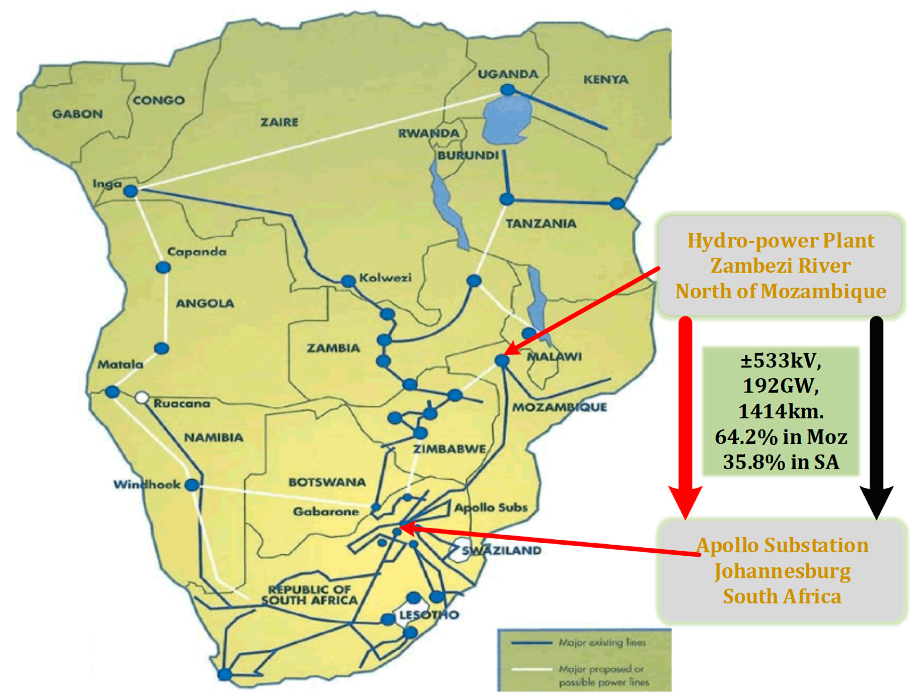
Figure 2 shows the SAPP network.
4. Cahora Bassa HVDC Scheme
Cahora Bassa HVDC link is a thyristor-based converter scheme that transmits 1920 MW of electrical power from a hydroelectric power plant located in the Zambezi River, north of Mozambique, to Johannesburg, South Africa. The rectifier station, located at Songo in Mozambique, is connected to the Apollo inverter station in Johannesburg over 1414 km, ±533 kV bipolar lines. A total of 64.2% of the transmission length is located in Mozambican territory, while 35.8% resides in South Africa. The link has approximately 7000 towers with an average span of 426 m of the transmission network. Reinforced towers with earth return are provided using buried graphite electrodes located at a considerable distance from the converter station. Smoothing reactors, surge arresters, and capacitor banks are installed at respective converter stations. The Apollo inverter station was refurbished in 2008, equipping it with 5″ electrically triggered thyristor valves capable of withstanding 3.3 KA, 8.5 kV switching capacity [
25].
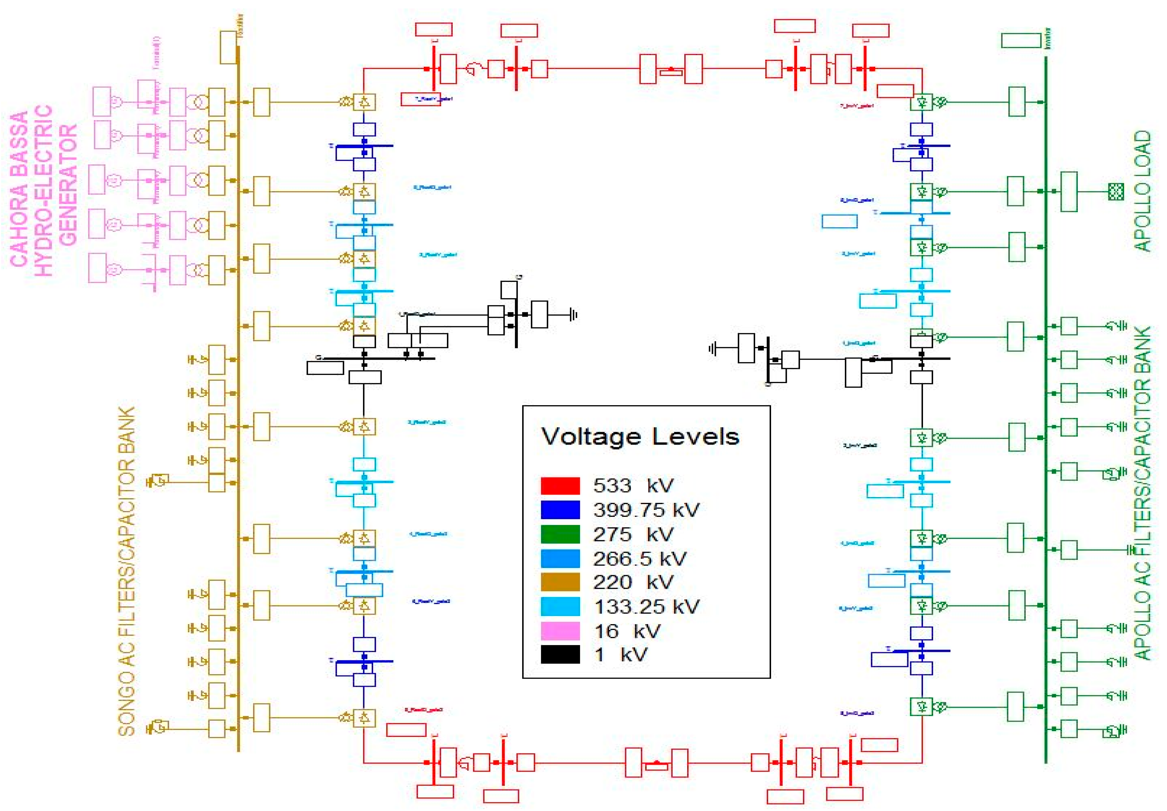
Figure 3 shows the detailed diagram of the Cahora Bassa HVDC scheme, which was modeled using DIgSILENT PowerFactory. The converter and transmission line data are shown in
Table 1 and
Table 2.
Figure 3 shows the hydro-power plant, low-frequency/high-frequency filter, and capacitor bank at the Songo rectifier station. The Apollo inverter station has the equivalent load (external grid) with different compensating devices installed.
5. Control Scheme
The HVDC controls on PowerFactory software can be divided into two levels: inverter control and rectifier control. A block definition that defines the transfer function in the form of graphical block diagrams and equations is first created for each controller. A composite block frame is then built for the overall control. This controller is then sub-divided into three hierarchical levels: power control, converter control, and pole control. Equations (8)–(10) show the quasi-steady mathematical model of a bipolar LCC HVDC scheme [
26]:
where +
Udc is the
dc voltage for the positive pole,
UY is the ac voltage,
αr is the rectifier firing angle, and
βi is the advance angle of the inverter.
X is the commutation reactance. Subscripts
R and
I stand for rectifier and inverter, respectively.
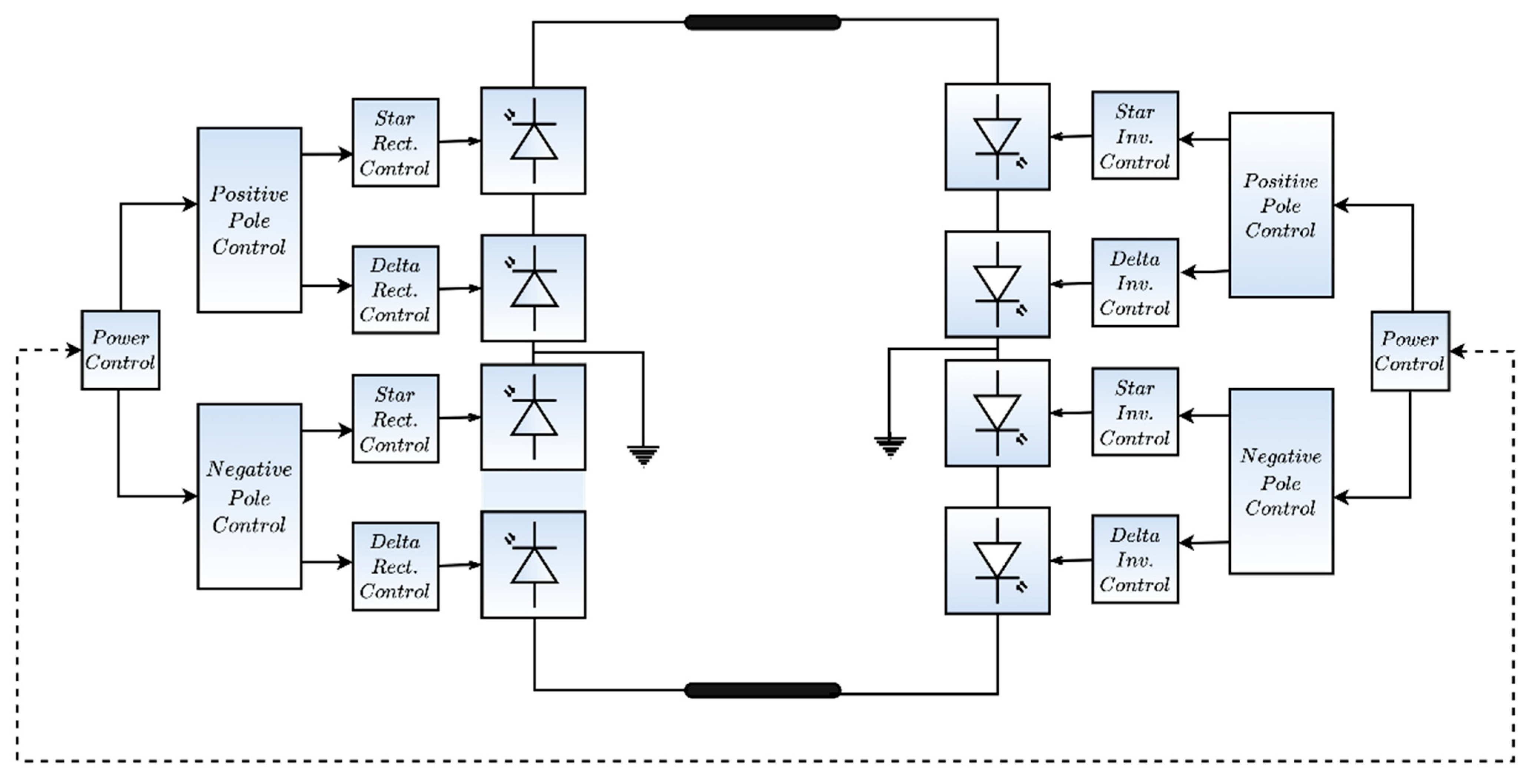
The overview diagram shows all the slots/interconnections and which object should be assigned to a slot. A standard model was created from the block definition and then added to the composite model.
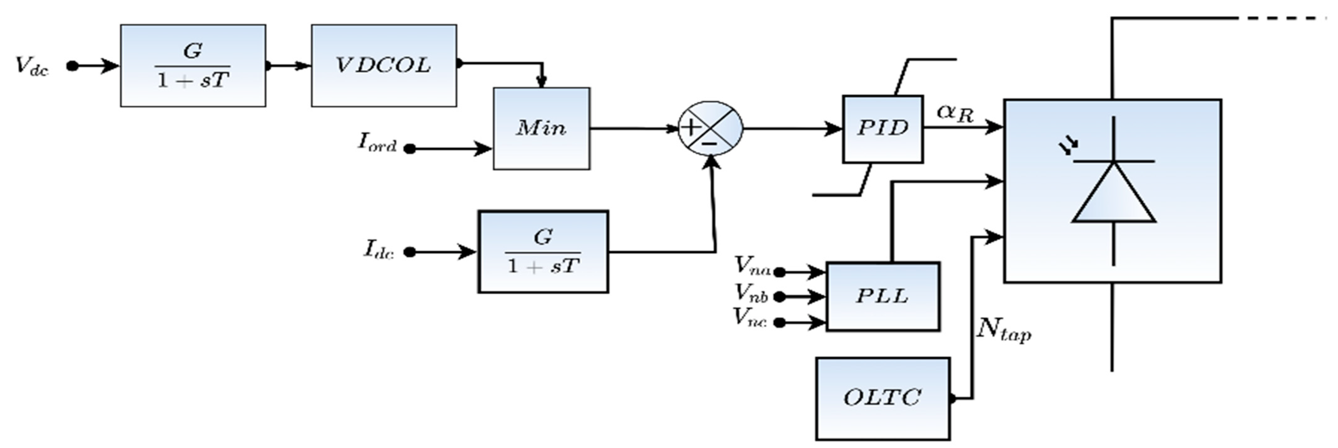
Figure 4 and
Figure 5 show a simple overview diagram of the controller connected to the converter. The functions of these major controllers of the HVDC converter are discussed briefly.
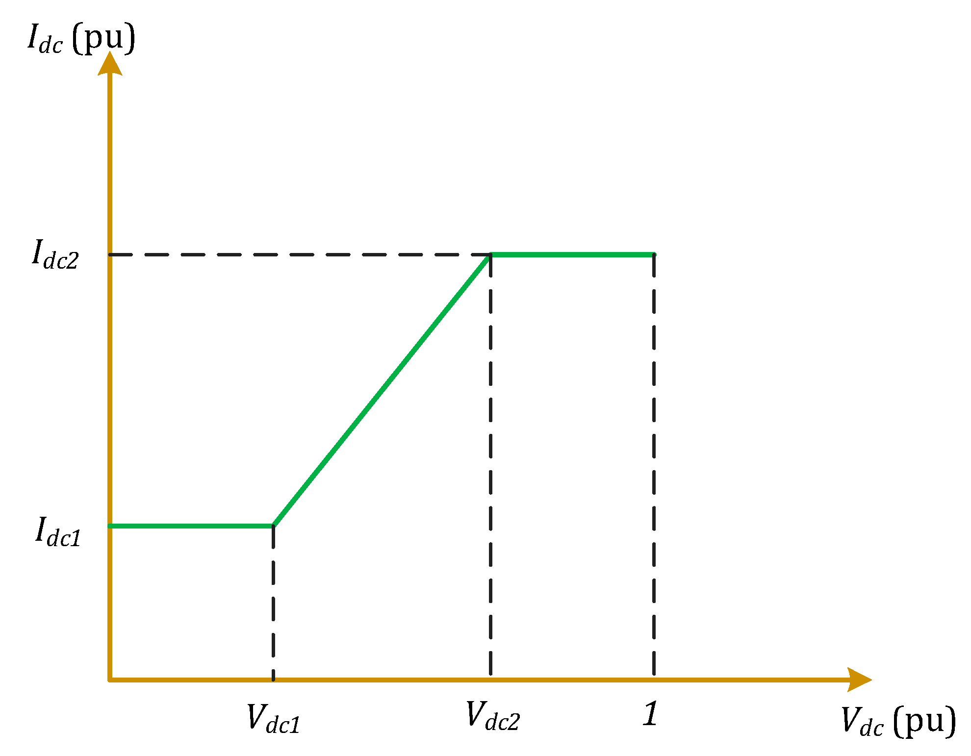
Voltage-Dependent Current Order Limiter (VDCOL): The VDCOL function reduces the current order value when there is a disturbance that causes a reduction in the DC voltage. The converter tracks the current order on the table based on the filtered DC voltage, as shown in
Figure 5. This control prevents a high rate of reactive power consumption and reduces voltage stress in the valve, thus facilitating the recovery of the converter after a disturbance. With the input voltage of
Vcd1, which connotes starting voltage of VDCOL, current
Idc1 is the current order produced by VDCOL. The static relationship between the dc voltage and current can be described in Equation (11) [
27,
28,
29].
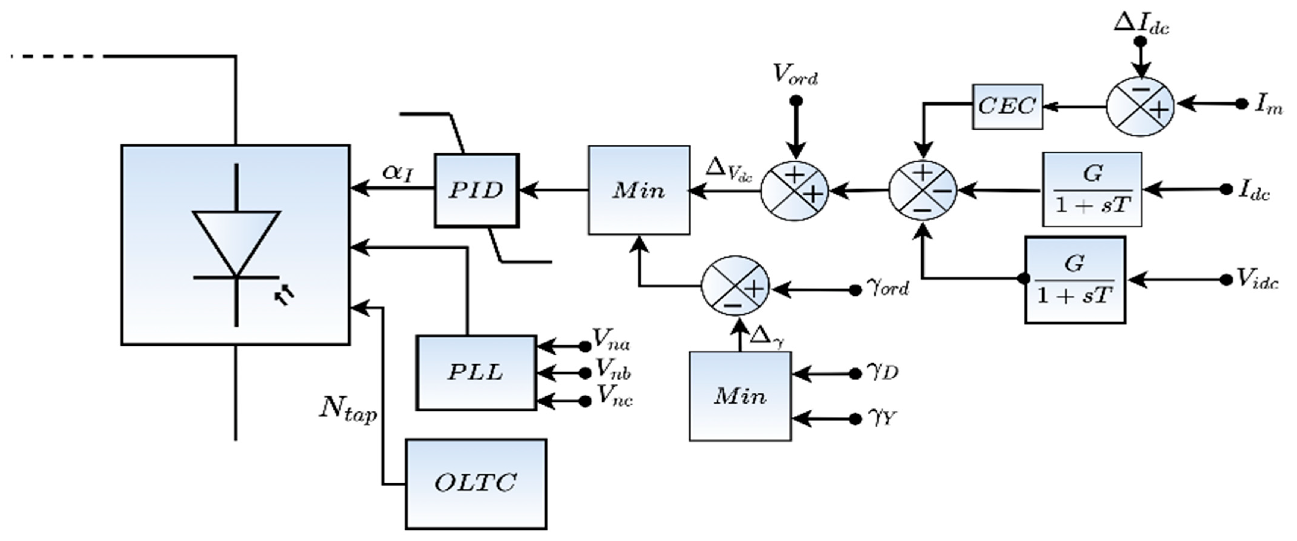
Current Controller: This controller filters the actual direct current measured, calculates the difference against the reference signal, and feeds the current error into a Proportional Integral (PI) controller, producing the firing angle order. The rectifier always operates as a current controller while the inverter uses the gamma controller due to the minimum value selector. The control block diagram for this controller is shown in
Figure 6 [
19,
30,
31].
Gamma Controller: This is also known as the extinction angle controller (
Figure 7). This controller ascertains that the commutation is complete before the polarity of the voltage across the valve turns positive during an inverter operation of the converter. The firing angle order used in the gamma controller is obtained from a PI regulator that takes the differences between the commutation margin
γ (delay between the valve extinction and the valve voltage just before turning positive) and a fixed set point. Where the margin is larger than necessary, the PI controller stops at the α-max. Otherwise, the firing angle is reduced until
γ equals the set value [
32,
33].
Converter Controller: This controller is the firing pulse generator. It generates each valve firing pulse by comparing the reference signal from the Phase-locked Loop (PLL).
Power Controller: This serves as the master controller that coordinates and oversees the overall control actions of the systems. It determines the current order signals for each pole of the converter.
6. Performance Analysis
The Cahora Bassa HVDC scheme was simulated and studied using the EMT tools to analyze the voltage and current distortion during a three-phase short circuit fault. An inverter fault was considered because of its severity on the HVDC link rather than a rectifier station fault. This inverter fault increases the rate of commutation failure at the inverter station. Thus, a three-phase short circuit with X
L = 10 Ω faults reactance was applied at the inverter AC busbar for t = 100 ms, using an electromagnetic EMT simulation tool for 0.4 s simulation time. The busbar voltage and converter current are shown in
Figure 8.
Figure 8a,b shows the inverter and the rectifier voltage, respectively. These plots show the voltage profiles in pu of the two substations. During the AC system fault at 0 s, the rectifier station (Songo) slightly reduces the bus voltage profile. This voltage gradually increases to its steady-state condition as the fault time progresses. However, the inverter station (Apollo) experiences a continuous dip in the voltage profile till the end of the fault time at 0.1 s.
Figure 8c,d shows the inverter and rectifier converter current. The converter AC current rises while the inverter station suffers commutation failure. It can be observed that, though the system regains its steady-state condition after successful clearing of the fault, the AC voltage waveform, which was expected to be purely sinusoidal, had few distortions. Furthermore, the current waveform of an LCC HVDC is typically trapezoidal rather than a perfect sinusoidal shape, coupled with commutation failure at the inverter side.
7. VSC HVDC Scheme
7.1. Introduction to VCS HVDC
Voltage Source Converter (VSC) uses Insulated Gate Bipolar Transistor (IGBT) technology. It was proposed in 2003 by Rainer Marquardt [
34]. It creates its own AC voltages in case of black start, thus helping the current to be switched on and off at any time independent of the AC voltage. Its converters operate at a high frequency with pulse width modulation (PWM), which allows simultaneous adjustment of the amplitude and phase angle of the converter while keeping the voltage constant. It has a high degree of flexibility with an inbuilt capability to control its active and reactive power, making it more useful in urban power network areas. Most VSC-HVDC technology converter stations use multilevel converter circuits [
35,
36], as shown in
Figure 9 and
Figure 10. Recent VSC HVDC installations around the globe are shown in
Table 3 [
37,
38].
7.2. Control Scheme
Independent control of power at each converter is possible. A converter controls the DC voltage at the link to match the nominal level, while the other converter sets the amount of active power through the link. Active and reactive power control is achieved with a phase reactor from the series inductance between the converter and the AC grid Equations (12) and (13) [
39,
40].
where
X represents the series reactance of the phase reactor and the transformer in the converter station.
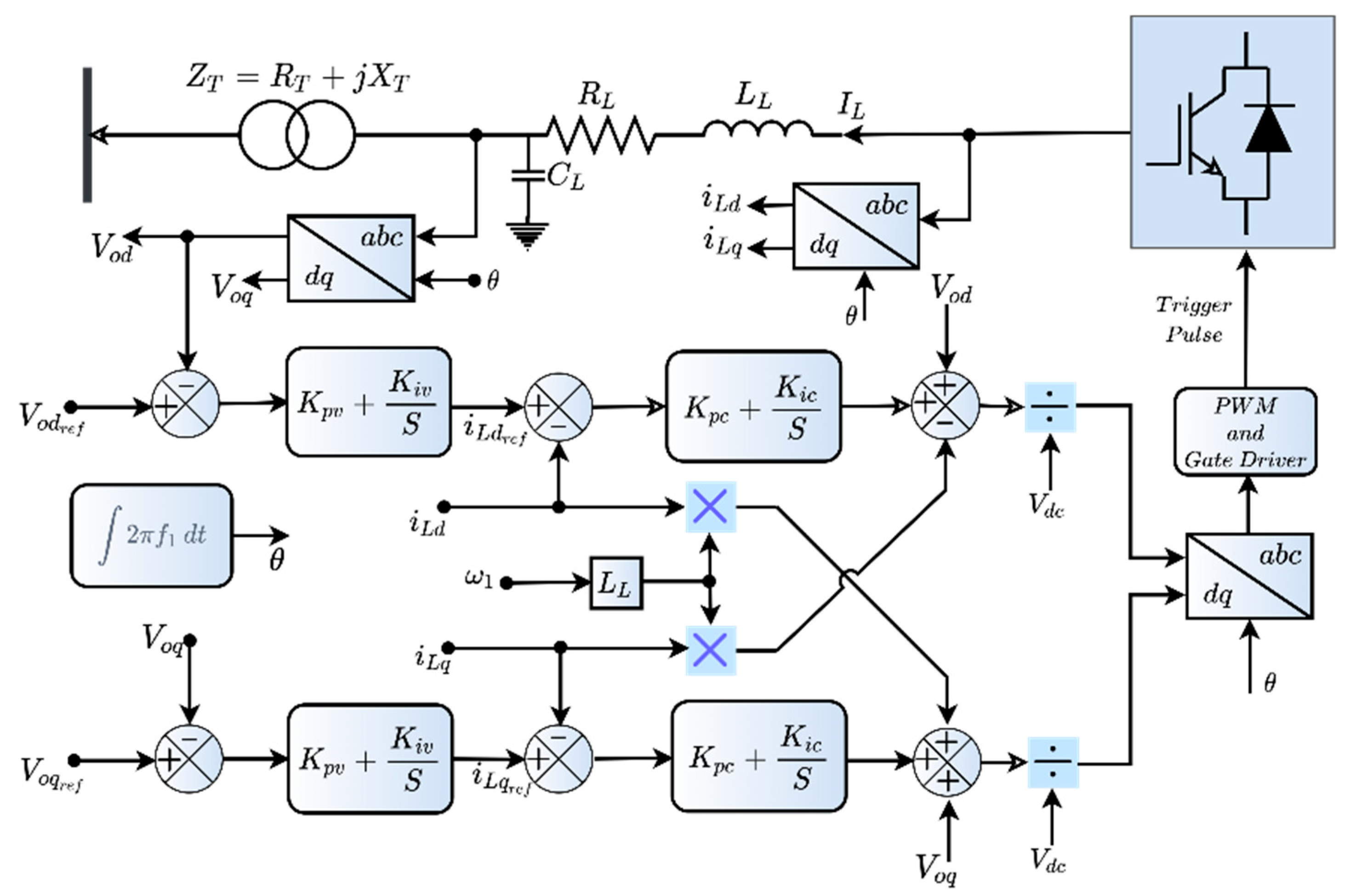
The VSC-HVDC control used for this study is based on a generic structure provided by DIgSILENT Power Factory. This control structure is shown in
Figure 11. This controller consists of two composite controller blocks for the rectifier and inverter station. The inverter composite model houses the three controller blocks; the main controller, the current controller, and the chopper controller block. The current limiter prioritizes the active current
Id during normal operation and then limits the reactive current
Iq. However, during a fault period of (v < v
0 − V
t), the active current is limited while the reactive current is prioritized. This main controller uses the first-order lag filter (lowpass) of 10 ms and 30 ms filter time on both the measured AC voltage and reactive power. The output current from the main controller is used as the current reference value for the current controller block, which is then used to generate the modulation index. Negative and positive DC voltage is fed into the chopper control block. This is used to ignite the DC valves of the chopper resistors if the voltage exceeds a certain limit. If the voltage drops again below a defined threshold, it then blocks these valves. These choppers are used as a protective measure against faults on the IGBT valves.
The desired active and reactive power of the VSC can be determined as in Equation (14): where
P and
Q are the desired active and reactive power of the VSC, respectively. In addition,
Vd and
Vq are the
d- and
q-axis voltage levels at the PCC, respectively.
Id and
Iq can be controlled directly by picking their corresponding reference values because the voltage is considered to be constant (
Id.
ref and
Iq.
ref) (Equation (15)) [
41,
42].
This analysis is equally relevant when the outer loop uses
P and
V controls since the
V control can be seen as a
Q control with a variable
Q reference. The
V control is recommended over the
Q control in weak AC grids. Thus, the
V control was used in this study. The vector control’s inner loop is designed using the inductor model between the point of common coupling and the VSC. The inner loop’s mathematical model is shown in Equation (16) [
39,
41,
43].
The rectifier controller maintains the AC grid voltage and the system frequency at a constant acceptable value. Measuring devices are used to detect the AC voltage, converter AC current, and positive and negative DC voltage. Phase-locked loops are also deployed to measure the AC phase voltages. This measuring point gives this controller a certain setpoint to keep the voltage magnitude and frequency constant. This is carried out through the input signal “Pm” (modulation index) and “f0” (frequency) of the PWM converter. The modulation index is controlled through two cascaded PI controllers and a feed-forward path using a measured DC voltage.
The first PI controller obtains the AC voltage deviation as the input signal. Its output is the reactive current reference. This reference signal is compared against the measured reactive current. The output of the second PI controller is then the reference voltage. The controller has two additional functions; it has a built-in limitation of the reactive current. This limitation becomes active only in case of a fault at the rectifier station, and the control can raise the frequency in the rectifier network in case of a high DC voltage.
8. Re-Engineering Using VSC-HVDC
Based on operation records, it is recognized that the Cahora Bassa LCC-HVDC scheme is largely responsible for instabilities in the Eskom EHV network due in part to aging infrastructure. A re-engineering was proposed using the VSC-HVDC scheme. This improves system performance, betters power controllability, and enhances stability margins.
A VSC-HVDC scheme was modeled using ±500 kV, 1500 MW on DIgSILENT PowerFactory (
Figure 12). The parameters are shown in
Table 4.
A three-phase short circuits fault of XL = 10 Ω fault reactance was also applied at the AC busbar of the inverter station and cleared at t = 100 ms. This compares the impact of the 3-phase fault with an LCC-HVDC and VSC-HVDC system by evaluating the harmonics distortions generated after the fault using the waveforms generated during and after the fault condition.
During a three-phase short circuit fault at the inverter AC station, the busbar voltage profile and the converter current was observed on the subplot in
Figure 13. From these plots, the rectifier, Songo substation, voltage (
Figure 13b), and converter current (
Figure 13d) were unaffected during the fault. The inverter voltage profile in
Figure 13a experiences a dip while the converter current recorded an increase in fault current throughout the duration of the fault. However, it maintains its steady-state condition after the fault period. Unlike the LCC-HVDC, the Songo voltage waveform suffered no reduction in bus voltage during the fault. It maintained ±1.00 p.u. peak to peak voltage. These results show that it minimizes fault condition transfer to the rectifier station.
From the VSC-HVDC converter current, neither the inverter nor the rectifier experienced a commutation failure during the fault. A slight increase in the current spike was observed at the instant of the fault occurring until the fault was cleared. Unlike the LCC-HVDC scheme, the system retained its sinusoidal waveform after the fault, which had to rebuild its converter current.
It was observed that the VSC-HVDC produced a perfect sinusoidal current waveform free of harmonic distortion, as shown in
Figure 14 (in
Table 5), compared to a trapezoidal waveform of the LCC-HVDC scheme. The voltages showing ripples and harmonics are shown in
Figure 14a. The harmonic distortion with 11th, 13th, 23rd, and 25th harmonics contents can also be seen in
Figure 14b during the LCC HVDC scenarios.
It may be concluded that the VSC-HVDC scheme provides better stability enhancement to an AC system than the conventional LCC scheme. The stability enhancement may be due to the high-frequency VSC HVDC switches during converter operation, which cannot be achieved in the LCC-HVDC scheme. However, this high switching frequency rate results in higher power losses and heat production. Furthermore, a modern VSC circuit can override this challenge. Thus, with the ongoing technological advancement of different VSC converter circuits, feasible technical solutions are desired or required for high-power transmission systems with reduced transmission losses.
9. Conclusions
The power transfer via the Cahora Bassa LCC HVDC link contributes largely to the stability of the South African power grid. However, the harmonics content generated due to the imperfection in LCC HVDC requires a large number of capacitors and inductor filters. Furthermore, the LCC line requires complex control of both the active and the reactive power. This study was carried out on the ±533 kV Cahora Bassa HVDC scheme to evaluate the system’s performance analysis. A solid three-phase short circuit was applied to the network at the AC side of the inverter station. The results show that this LCC HVDC link contributes some harmonic and current distortion to the South African grid. This becomes worse during load-shedding. The network analysis showed that the LCC-HVDC has limitations with respect to harmonic distortion, imperfect current waveform, and frequent commutation failure at the inverter side of the converter station during a worst-case scenario of three-phase short circuits fault. A better means of power transfer with enhanced system stability with a suitable sinusoidal waveform is therefore proposed using VSC-HVDC technology. A total harmonic distortion analysis was carried out, which shows that the proposed implementation of VSC HVDC reduces the harmonics distortion at the AC side of the inverter station and better recovers post fault time
The future implementation of this network VSC HVDC will enhance better stability of the South African power grid, reduce harmonics content, and provide better controllability of active and reactive power of the grid. It should be pointed out that challenges such as high fault current and losses are paramount to VSC HVDC schemes. However, with the recent advancement in semiconductor devices, research in the area of DC circuit breakers, and VSC fault ride-through capabilities, the VSC HVDC provides a better option for system controllability and improved stability. Future research areas include the hybrid implementation of the LCC and VSC HVDC on the Cahora Bassa HVDC link.
Author Contributions
Conceptualization, O.E.O. and I.E.D.; methodology, O.E.O., I.E.D. and A.A.; software and validation, O.E.O., A.A. and E.B.; formal analysis, O.E.O., A.A. and E.B.; investigation, O.E.O., A.A. and E.B.; resources, O.E.O. and I.E.D.; data curation, O.E.O. and I.E.D.; writing—original draft preparation, O.E.O. and I.E.D.; writing—review and editing, O.E.O., A.A., I.E.D. and E.B.; supervision, I.E.D.; project administration, I.E.D.; funding acquisition, I.E.D. All authors have read and agreed to the published version of the manuscript.
Funding
This research study received no external funding.
Acknowledgments
The authors acknowledge the facility support from the Durban University of Technology Smart Grid Research Center.
Conflicts of Interest
The authors declare no conflict of interest.
References
- Ogunboyo, P.T.; Tiako, R.; Davidson, I.E. Effectiveness of dynamic voltage restorer for unbalance voltage mitigation and voltage profile improvement in secondary distribution system. Can. J. Electr. Comput. Eng. 2018, 41, 105–115. [Google Scholar] [CrossRef]
- Sharma, A.; Rajpurohit, B.S.; Singh, S. A review on economics of power quality: Impact, assessment and mitigation. Renew. Sustain. Energy Rev. 2018, 88, 363–372. [Google Scholar] [CrossRef]
- Aziz, M.H.A.; Azizan, M.M.; Sauli, Z.; Yahya, M.W. A review on harmonic mitigation method for non-linear load in electrical power system. In AIP Conference Proceedings; AIP Publishing LLC: Melville, NY, USA, 2021; p. 020022. [Google Scholar]
- Lamedica, R.; Ruvio, A.; Ribeiro, P.F.; Regoli, M. A Simulink model to assess harmonic distortion in MV/LV distribution networks with time-varying non linear loads. Simul. Model. Pract. Theory 2019, 90, 64–80. [Google Scholar] [CrossRef]
- Madhu, B.; Mn, D.; Bm, R. Design of shunt hybrid active power filter (SHAPF) to reduce harmonics in AC side due to Non-linear loads. Int. J. Power Electron. Drive Syst. 2018, 9, 1926. [Google Scholar]
- Belany, P.; Bolf, A.; Novak, M.; Roch, M. The impact of small non-linear load operation on accuracy of the intelligent measurement system. In Proceedings of the 2018 International Conference and Exposition on Electrical And Power Engineering (EPE), Iasi, Romania, 18–19 October 2018; pp. 247–252. [Google Scholar]
- Rodrigues Limongi, L.; Bradaschia, F.; Hermann de Oliveira Lima, C.; Cabral Cavalcanti, M. Reactive power and current harmonic control using a dual hybrid power filter for unbalanced non-linear loads. Energies 2018, 11, 1392. [Google Scholar] [CrossRef] [Green Version]
- Dai, J.; Shokooh, F. Industrial and Commercial Power System Harmonic Studies: Introduction to IEEE Standard 3002.8-2018. IEEE Ind. Appl. Mag. 2021, 28, 51–64. [Google Scholar] [CrossRef]
- Tang, H.; Wu, G.; Deng, J.; Chen, M.; Li, X.; Liu, K. Electro-thermal comprehensive analysis method for defective bushings in HVDC converter transformer valve-side under multiple-frequency voltage and current harmonics. Int. J. Electr. Power Energy Syst. 2021, 130, 106777. [Google Scholar] [CrossRef]
- Zhao, C.; Xia, J.; Guo, C.; Zhan, R. An improved control strategy for current source converter-based HVDC using fundamental frequency modulation. Int. J. Electr. Power Energy Syst. 2021, 133, 107265. [Google Scholar] [CrossRef]
- Behram, B.; Ahmad, S.; Shoukat, A.; Khan, S.S. Fabrication of Three-phase Automatic Transfer Switching System with Reduced Switching Time. In Proceedings of the 2021 16th International Conference on Emerging Technologies (ICET), Islamabad, Pakistan, 22–23 December 2021; pp. 1–4. [Google Scholar]
- Liao, J.; Zhou, N.; Wang, Q. DC-side harmonic analysis and DC filter design in hybrid HVDC transmission systems. Int. J. Electr. Power Energy Syst. 2019, 113, 861–873. [Google Scholar] [CrossRef]
- Luo, S.; Dong, X.; Shi, S.; Wang, B. A directional protection scheme for HVDC transmission lines based on reactive energy. IEEE Trans. Power Deliv. 2015, 31, 559–567. [Google Scholar] [CrossRef]
- Mbangula, K.; Davidson, I.; Tiako, R. Improving power system stability of South Africa’s HVAC network using strategic placement of HVDC links. CIGRE Sci. Eng. J. 2016, 5, 71–78. [Google Scholar]
- Das, J. Power System Harmonics and Passive Filter Designs; John Wiley & Sons: Hoboken, NJ, USA, 2015. [Google Scholar]
- Xiao, H.; Li, Y.; Duan, X. Enhanced commutation failure predictive detection method and control strategy in multi-infeed LCC-HVDC systems considering voltage harmonics. IEEE Trans. Power Syst. 2020, 36, 81–96. [Google Scholar] [CrossRef]
- Lu, J.; Yuan, X.; Zhang, M.; Hu, J. A supplementary control for mitigation of successive commutation failures considering the influence of PLL dynamics in LCC-HVDC systems. CSEE J. Power Energy Syst. 2020. [Google Scholar] [CrossRef]
- Luu, K.T.; Han, M.; Tang, X. Background Harmonic Transfer and Mitigation in a Two-Terminal MMC-HVDC System. In Proceedings of the 2019 IEEE 3rd International Electrical and Energy Conference (CIEEC), Beijing, China, 7–9 September 2019; pp. 915–920. [Google Scholar]
- Abedin, T.; Lipu, M.S.H.; Hannan, M.A.; Ker, P.J.; Rahman, S.A.; Yaw, C.T.; Tiong, S.K.; Muttaqi, K.M. Dynamic modeling of hvdc for power system stability assessment: A review, issues, and recommendations. Energies 2021, 14, 4829. [Google Scholar] [CrossRef]
- Oni, O.E.; Davidson, I.E. Harmonie distortion of LCC-HVDC and VSC-HVDC link in eskom’s cahora bassa HVDC scheme. In Proceedings of the 2016 IEEE International Conference on Renewable Energy Research and Applications (ICRERA), Birmingham, UK, 20–23 November 2016; pp. 484–489. [Google Scholar]
- Selvaraj, D.E.; Priyan, K.G.; Alam, F.; Singh, V.K.; Meeran, A.S.M.; Sugumaran, C.P. A Short note on Harmonics and Filters in HVDC systems. J. Club Electr. Eng. 2014, 1, 17–26. [Google Scholar]
- Bowa, K.; Mwanza, M.; Sumbwanyambe, M.; Ulgen, K.; Pretorius, J. Comparative Sustainability Assessment of Electricity Industries in Sadc Region: The Role of Renewable Energy in Regional and National Energy Diversification. In Proceedings of the 2019 IEEE 2nd International Conference on Renewable Energy and Power Engineering (REPE), Toronto, ON, Canada, 2–4 November 2019; pp. 260–268. [Google Scholar]
- Mwale, S.J.; Davidson, I.E. Security analysis of electric power supply in SADC region. In Proceedings of the 2013 Africon, Pointe aux Piments, Mauritius, 9–12 September 2013; pp. 1–6. [Google Scholar]
- Mwale, S.; Davidson, I. SADC Power Grid Reliability-A Steady-state Contingency Analysis and Strategic HVDC Interconnections Using the N-1 Criterion. In Proceedings of the 2nd International Symposium on Energy Challenges and Mechanics, Aberdeen, UK, 19–21 August 2014; pp. 19–21. [Google Scholar]
- Goosen, P.; Reddy, C.; Jonsson, B.; Holmgren, T.; Saksvik, O.; Bjorklund, H. In Upgrade of the Apollo HVDC converter station. In Proceedings of the CIGRÉ 6th Southern Africa Regional Conference, Somerset West, South Africa, 17–21 August 2009; pp. 1–6. [Google Scholar]
- Xie, Q.; Zheng, Z.; Wang, Y.; Hu, W.-X.; Xiao, X.; Du, K.; Ren, J. Analysis of Transient Voltage Disturbances in LCC-HVDC Sending Systems Caused by Commutation Failures. IEEE Trans. Power Deliv. 2022. [Google Scholar] [CrossRef]
- Kazi, M.A.; Majdoul, R.; El-Alami, A.; Baraka, I.; Machkour, N. Control and Protection of Hybrid LCC-VSC HVDC Transmission System based on VDCOL Strategy. Int. J. Electr. Eng. Inform. 2022, 14, 204–223. [Google Scholar]
- Zheng, C.; Tang, Y.; Wang, Q. VDCOL Coordinated Control Strategy for Successive Commutation Failure Mitigation in Multi-infeed HVDC Systems. In Proceedings of the 2021 IEEE Power & Energy Society General Meeting (PESGM), Washington, DC, USA, 26–29 July 2021; pp. 1–5. [Google Scholar]
- Oni, O.E.; Swanson, A.G.; Carpanen, R.P. Line Commutated Converter Response during Total and Partial De-Blocking of a Bipolar MTDC System. Int. J. Eng. Res. Afr. 2021, 52, 49–61. [Google Scholar] [CrossRef]
- Du, X.; Zhao, C.; Xu, J. The Use of the Hybrid Active Power Filter in LCC-HVDC Considering the Delay-Dependent Stability. IEEE Trans. Power Deliv. 2021, 37, 664–673. [Google Scholar] [CrossRef]
- Ahmed, A.; Khan, D.; Khan, A.M.; Mustafa, M.U.; Panjwani, M.K.; Hanan, M.; Agyekum, E.B.; Uhunamure, S.E.; Edokpayi, J.N. Modeling of Efficient Control Strategies for LCC-HVDC Systems: A Case Study of Matiari–Lahore HVDC Power Transmission Line. Sensors 2022, 22, 2793. [Google Scholar] [CrossRef]
- Xia, H.; Hong, L.; Zhou, X. Interaction paths analysis and stability-enhancing methods for LCC-HVDC system with weak receiving-end grid. Int. J. Electr. Power Energy Syst. 2022, 140, 108067. [Google Scholar] [CrossRef]
- Wu, X.; Xu, Z.; Zhang, Z. Power Stability Analysis and Evaluation Criteria of Dual-Infeed HVDC with LCC-HVDC and VSC-HVDC. Appl. Sci. 2021, 11, 5847. [Google Scholar] [CrossRef]
- Xing, Y.; Wang, H.; Zhang, T.; Wang, S.; Zhao, B.; Wang, T. An Improved NLM Strategy for MMC Emergency Power Control. In Proceedings of the 2020 IEEE/IAS Industrial and Commercial Power System Asia (I&CPS Asia), Weihai, China, 13–15 July 2020; pp. 1251–1255. [Google Scholar]
- Adam, G.P.; Davidson, I.E. Robust and generic control of full-bridge modular multilevel converter high-voltage DC transmission systems. IEEE Trans. Power Deliv. 2015, 30, 2468–2476. [Google Scholar] [CrossRef] [Green Version]
- Li, R.; Xu, L.; Yu, L.; Yao, L. A hybrid modular multilevel converter with reduced full-bridge submodules. IEEE Trans. Power Deliv. 2019, 35, 1876–1885. [Google Scholar] [CrossRef] [Green Version]
- Siemens-Energy. HVDC PLUS–The Decisive Step Ahead; Siemens-Energy: Munich, Germany, 2021. [Google Scholar]
- Hitachi-Energy. HVDC Light® Reference List: The Original VSC Technology. 2022. Available online: https://search.abb.com/library/Download.aspx?DocumentID=POW0027&LanguageCode=en&DocumentPartId=&Action=Launch (accessed on 22 March 2022).
- Li, Y.; Du, Z. Stabilizing Condition of Grid-Connected VSC as Affected by Phase Locked Loop (PLL). IEEE Trans. Power Deliv. 2021, 37, 1336–1339. [Google Scholar] [CrossRef]
- Ibrahim, N.F.; Dessouky, S.S. VSC-HVDC control system. In Design and Implementation of Voltage Source Converters in HVDC Systems; Springer: Berlin/Heidelberg, Germany, 2021; pp. 15–30. [Google Scholar]
- Xue, Y.; Luo, X.; Xie, J.; Ma, D.; Li, M. Influence and comparison of P/Q-control based VSC-HVDC system on the grid power oscillation damping. Energy Rep. 2022, 8, 1368–1377. [Google Scholar] [CrossRef]
- Buraimoh, E.; Davidson, I.E. Modeling of Double Stage Photovoltaic Inverter System with Fast Delayed Signal Cancellation for Fault Ride-Through Control Application in Microgrids. Energies 2022, 15, 701. [Google Scholar] [CrossRef]
- Buraimoh, E.; Davidson, I.E. Fault ride-through analysis of current-and voltage-source models of grid supporting inverter-based microgrid. IEEE Can. J. Electr. Comput. Eng. 2021, 44, 189–198. [Google Scholar] [CrossRef]
| Publisher’s Note: MDPI stays neutral with regard to jurisdictional claims in published maps and institutional affiliations. |
© 2022 by the authors. Licensee MDPI, Basel, Switzerland. This article is an open access article distributed under the terms and conditions of the Creative Commons Attribution (CC BY) license (https://creativecommons.org/licenses/by/4.0/).


