Article

Modification of Electromechanical Coupling in Electromagnetic Harvester

Department of Applied Mechanics, Lublin University of Technology, Nadbystrzycka 36 Street, 20-618 Lublin, Poland
Energies 2022, 15(11), 4007; https://doi.org/10.3390/en15114007
Submission received: 28 April 2022 / Revised: 23 May 2022 / Accepted: 26 May 2022 / Published: 30 May 2022
(This article belongs to the Special Issue Nonlinear Dynamics of Energy Harvesting Systems)

Abstract

:
This paper focuses on the modelling and analysis of electromechanical coupling in a magnetic levitation energy harvester. A prototype harvester is built and its performance is tested with a shaker under resonance conditions. In order to modify the electromechanical coupling, a specially designed coil stack consisting of four independent coils is proposed. The configuration of the coil and the gap between them change the shape of the electromechanical coupling function. The results obtained show that the proper configuration of the modular coil allows one to modify the shape of the electromechanical coupling, increasing the recovered energy, and widens the resonance operating bandwidth.

1. Introduction

1.1. Background

Energy harvester (EH) describes a device that can convert ambient energy into electricity. These devices have the potential to replace batteries due to their size, eco-friendliness and low maintenance costs [1]. Vibration is one of the most common sources of mechanical energy. Easy access to vibration sources makes vibration energy harvesters (VEHs) promising for various engineering applications [2]. VEHs seem to be a promising method to solve the energy supply problem, especially for small electronic devices [3].
The recovered energy of an electromagnetic harvester can vary depending on the design and conversion mechanism, characterized by a coupling between the mechanical and electrical systems [4]. Tang and Lin [5] proposed using a four-phase coil in one magnetic cycle to improve the power densities in linear electromagnetic transducers. It was found that radial magnets made a significant improvement to power density. Glynne-Jones et al. [6] improved energy recovery effectiveness by additional magnets, which increased the magnetic field. Foong et al. [7] increased the power output through anti-phase resonance. The classical magnetic levitation harvester modified by a cluster of peripheral solid magnet casing to introduce bi-stability was shown in [8]. The authors suggested that thinner peripheral magnets were more favorable for building bi-stable harvesters. Usually, electromagnetic harvesters are designed for micro and macro scales. Moreover, they operate in a frequency range from a few hertz to several hundred hertz [9].
A promising solution for low-frequency excitation is a harvester using the magnetic levitation phenomenon. Magnetic levitation (maglev) harvesters can work under low-frequency conditions and can be produced at an affordable cost [10]. It should be noted that when the size of a harvester device is reduced, mechanical resonances tend to increase in frequency. Therefore, energy recovery from comparatively low vibrational frequencies seems to pose a challenge. Moreover, maglev harvesters have a longer lifespan due to the use of a magnetically levitated effect instead of mechanical springs that wear out easily. Wei and Jing [11] showed and compared three main energy harvesting technologies, piezoelectric, electrostatic and electromagnetic, including different materials and types. The authors noted that the effective use of nonlinearities with guaranteed reliability, stability and performance was a difficult task, both in theory and practice. A new harvester consisting of a tri-stable nonlinearity-enhanced mechanism with a wider bandwidth under low-frequency excitation levels was presented in [12]. An interesting paper on magnetic levitation harvesters was presented by Caneiro et al. [13]. The authors performed a rigorous analysis of twenty-one design configurations and compared their geometric and constructive parameters, optimization methodologies and energy harvesting effectiveness. Moreover, most analytical, semi-analytical, empirical and finite element models including transduction mechanisms were discussed. Maglev harvesters with a single coil and multiple magnets were presented in [14,15,16,17]. A detailed formulation for modeling levitation-based vibration energy harvesters was given in [18]. The response of a harvester under specific finite displacements–finite rotation excitations was investigated.
Electromechanical coupling (EC) is defined as the ability to convert mechanical energy into electrical energy. Usually, this parameter is significantly simplified due to the assumption that the magnetic field is constant. Therefore, electromechanical coupling is considered to have a constant value [19,20,21,22,23]. In paper [24], a new method of experimentally determining EC by quasi-static and dynamics tests was described. The authors proposed a mathematical model of EC as a polynomial nonlinear function (odd polynomial function of thirteen degrees). Moreover, they stated that the constant EC could be used if properly chosen. In another study [25], the EC model was modified by locating the oscillated magnet in the coil.
The EC was also investigated as nonlinear in [26,27]. It was obtained as the sum of the electromagnetic coupling coefficients of every coil turn. Some researchers described the electromechanical interaction by the Lorentz force [28,29]. Mosch and Fischerauer [30] compared several methods to determine the EC coefficients. The EC was determined by the finite element method (Ansys Electromagnetics) by evaluating the measured optimum load resistance and resonance curve, and based on the linear variation of the current. The maximum observed deviation was up to 8%. However, the authors recommended determining the EC based on the optimum load resistance and open circuit method. An analytical relation between the electromechanical coupling coefficient and the magnet position using the magnetic dipole theory is presented in [31,32]. Cannarella et al. [33] demonstrated that the EC described in a simplified form as the product of the number of coil turns, the average magnetic induction field and the length of a single coil turn can lead to errors in the estimation of the harvested electric power. Similar conclusions were drawn in [34]. The authors suggested that for nonlinear dynamical harvesters, many of the simplifications normally satisfied by linear systems did not apply. Recently, Saravia [35] numerically compared two electromechanical coupling formulations. It was suggested that the classical approach of the electromechanical coupling as the electrical damping could lead to inconsistency.
In Section 2, the design and structure of magnetic levitation are described. Section 3 presents the models of electromechanical coupling for different configurations of a modular coil. Finally, in Section 4, discussions of a frequency response analysis in the first and second resonances and the influence of resistance are presented.

1.2. Motivation

The impetus for this paper was to find a method for the simple modification of the EC function. The novelty of this paper is the study of a coil stack (modular coil) consisting of four coil modules (separate coils). These coils can be activated independently of each other; this means that a gap between coils can be changed. This leads the electromechanical coupling shape to be changed from the classical form (sinusoidal) to a more complicated one.
As shown in the literature review, there are no papers dedicated to the problem of the modification and shaping of electromechanical coupling. This harvester is planned be applied as a dynamical damper [36,37]. Therefore, it is necessary to find a method of controlling energy harvesting without changing the harvester’s parameters.

2. Harvester Design and Methods

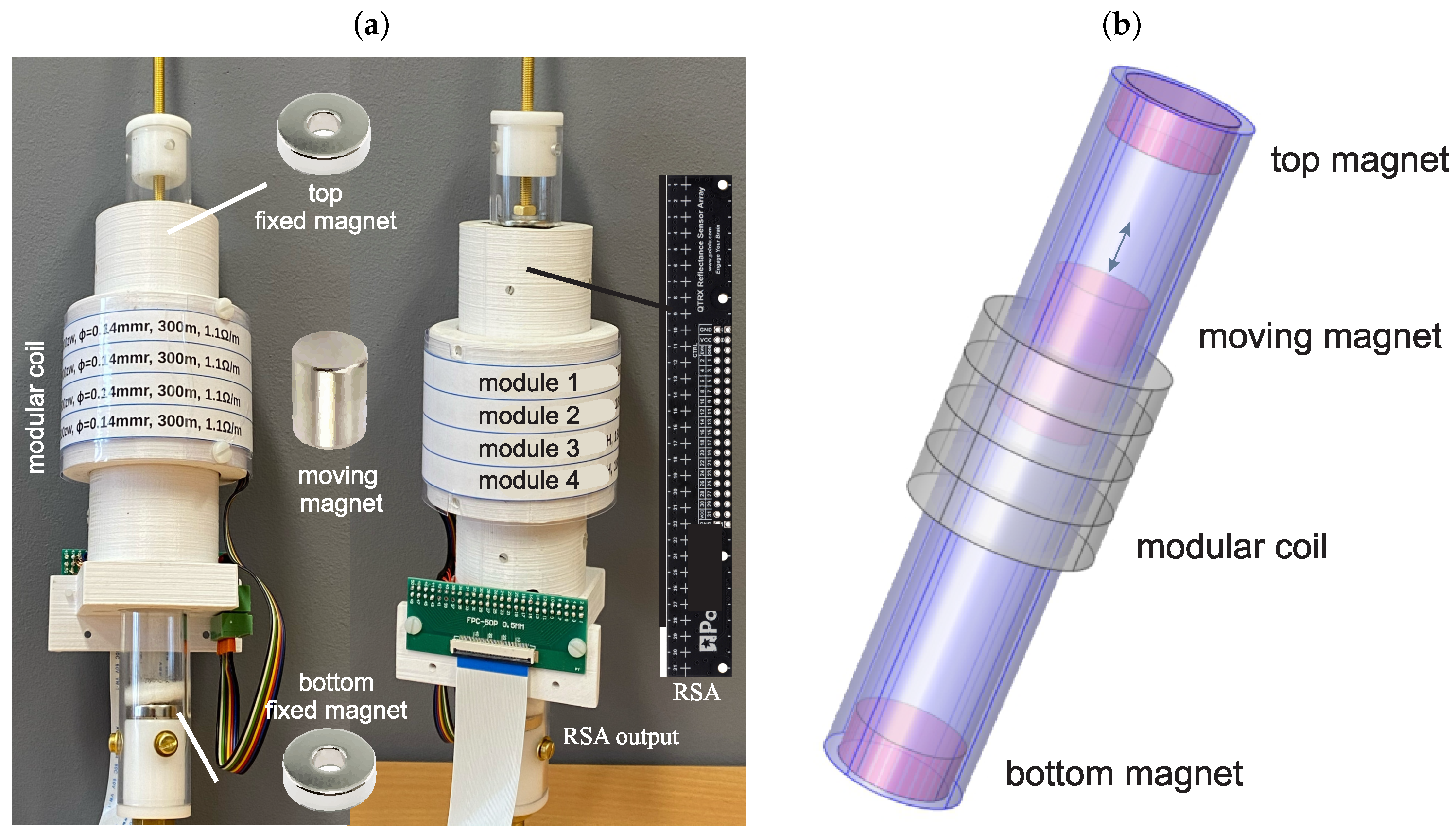
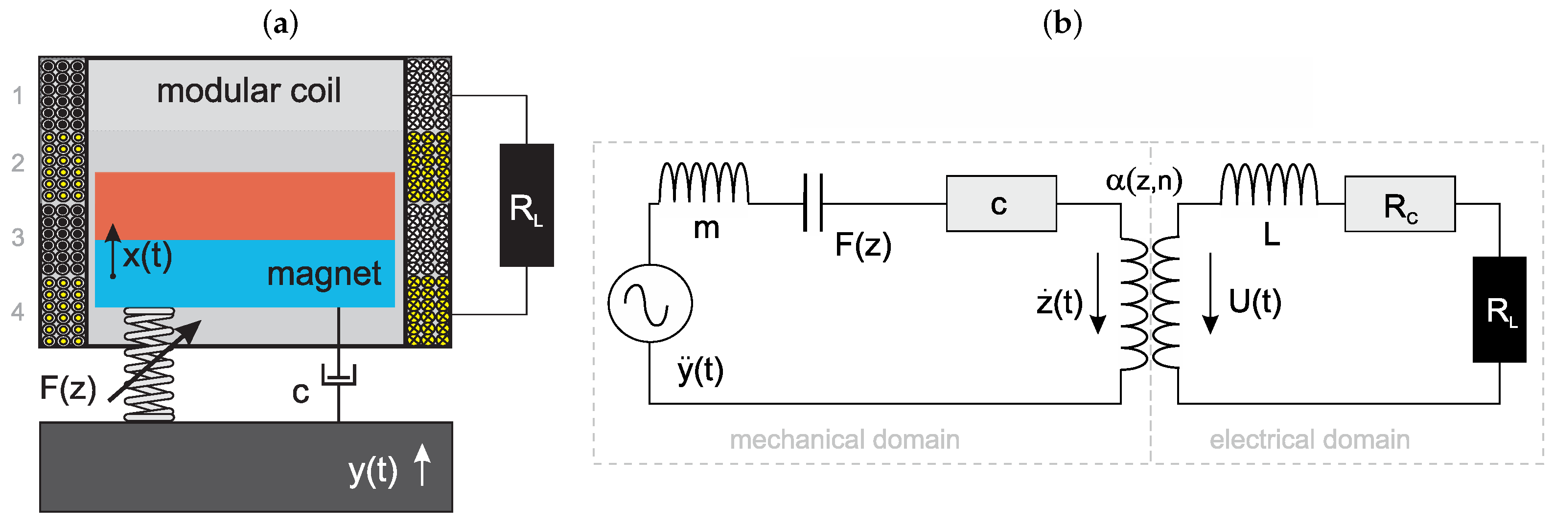
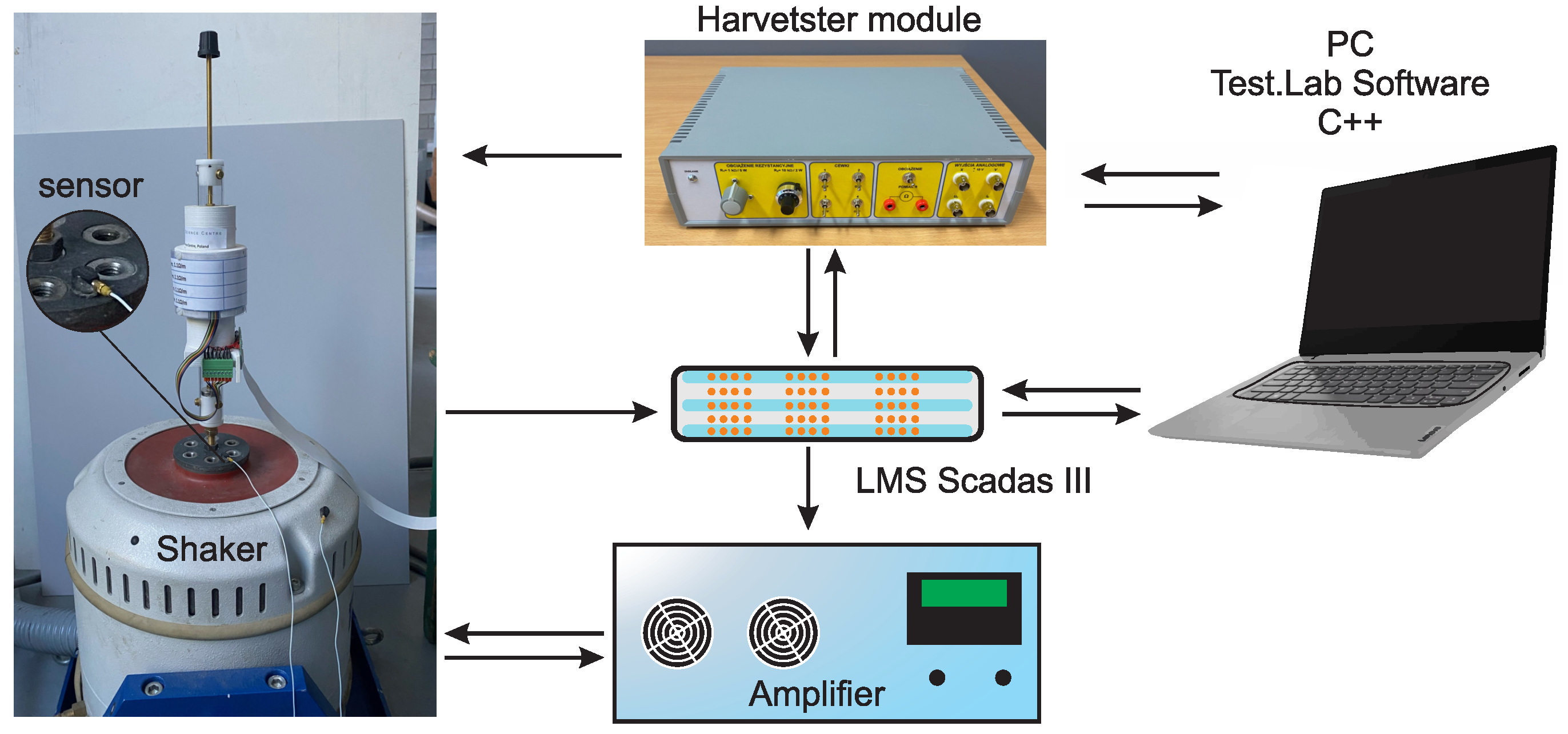
2.1. Prototype Harvester

This prototype electromagnetic harvester consists of a nonmagnetic hollow cylinder, two fixed and one moving magnets and a specially designed modular coil consisting of four separate coils, which can be activated independently (Figure 1). Two opposite-polarity circular magnets (top and bottom magnets) are mounted on the coil’s ends.
The third floating magnet moves inside the cylinder between the fixed magnets and is subjected to a repulsive (levitation) force from each magnet. The tube is equipped with two bumpers, which causes a reduction in the magnet’s collision. On the cylinder portion, a specially designed modular coil is mounted. Its position can be modified as required. The magnet moving axially through the coil induces voltage across the coil modules. Figure 1 shows the prototype harvester that has been built. The modular coil consists of four separate segments connected in series. Parameters of the four coil modules are given in Table 1.
Given the difficulty of magnet measurement, especially when the magnet is placed in the modular coil, a special reflectance sensor array (RSA), QTRX-HD-31A, was used in the coil structure. The RSA system consists of 31 phototransistor pairs and works as a line sensor. By precisely identifying changes in reflectance, it is possible to estimate the magnet’s velocity and displacement. The prototype harvester is connected to the data acquisition system of the harvester.
Analogue outputs in the harvester’s module allow the module to be connected to a data acquisition system (LMS). The harvester was tested using a Tira shaker, LMS Scadas III, amplifier, harvester module, as well as an accelerometer to determine the shaker acceleration at different frequencies and a computer with the LMS Test.Lab v.14 and own software prepared in C+ software. The fixture and (total) experimental setup are shown above, in Figure 2.

2.2. Equations of Motion

Magnetic levitation harvesters are commonly modeled by the lumped-parameter equivalent model. The harvester is modeled as a mass–spring–dashpot system, as shown in Figure 3a, with a coupled electrical circuit. The electrical circuit consists of a coil with a resistance R C , an inductance L and a resistance load R L . All these electrical elements are connected in series. Both domains are linked by an electromagnetic coupling coefficient α ( z , n ) . This parameter describes the efficiency of energy conversion and depends on the magnet position in the modular coil and active coil modules.
A coupled electromechanical model representation of the total harvester is shown in Figure 3b.
The electrical–mechanical system is governed by two second-order differential equations that connect the magnet motion with the induced current.
m z ¨ ( t ) + c z ˙ ( t ) + F ( z ) + α ( z , n ) i ( t ) = m y ¨ ( t ) m g
L i ˙ ( t ) + ( R L + R C ) i ( t ) α ( z , n ) z ˙ ( t ) = 0
where m and c are the equivalent magnet mass and the viscous damping that results from the friction between the magnet and coil as well as from air damping. z ( t ) is the relative displacement of the floating magnet z ( t ) = x ( t ) y ( t ) , where y ( t ) represents the input base excitation and x ( t ) is the displacement of the magnet. Thus, the coordinate of z ( t ) defines the vibration of the moving magnet only. Parameter n denotes the number of active coil modules, and F ( z ) is the magnetic repulsion force. The excitation y ( t ) = A s i n ( ω t ) is expressed as harmonic oscillation with an acceleration magnitude A and an angular frequency ω . The operator (·) is defined as differentiation with respect to time t.
Equation (2) is based on Kirchhoff’s Voltage Law and describes the induced voltage U ( t ) across the external resistor R L . The electromechanical coupling is related to Faraday’s law of electromagnetic induction [30]
U ( t ) N d φ d t = N d φ d z z ˙ ( t ) = : α ( z , n ) z ˙ ( t ) ,
where N denotes the number of coil turns, and φ is the magnetic flux for a single coil turn.
The system has two degrees of freedom: relative displacement z ( t ) and induced current i ( t ) . The nonlinearity of the harvester comes from the varying vibration amplitude, nonlinearity of the magnetic suspension and nonlinearity of the electromechanical coupling.

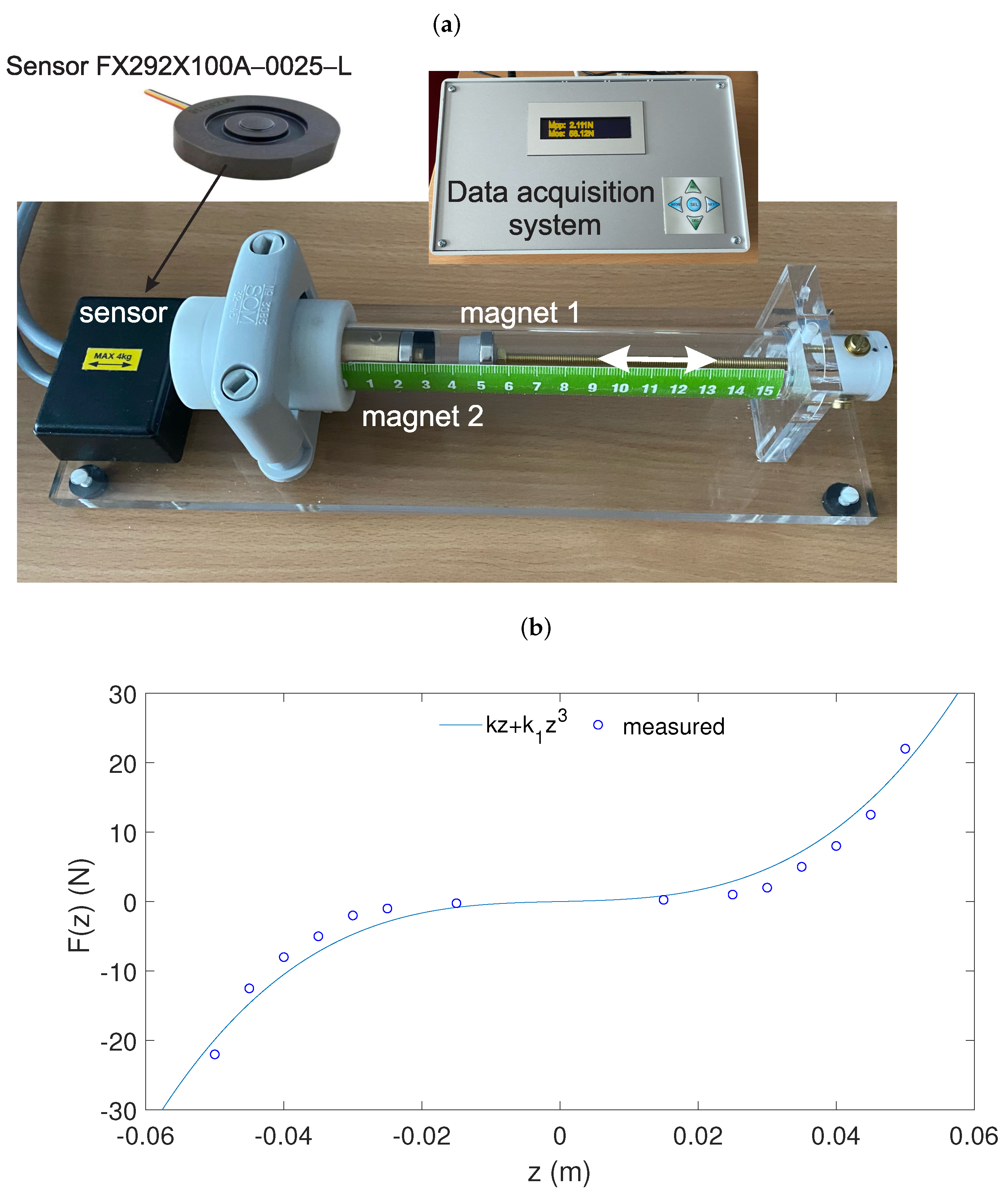
2.3. Magnetic Suspension

The springiness of the magnetic suspension is directly correlated with the fixed and moving magnets. By varying their dimensions, masses, magnetization or the distance between them, it is possible to obtain different nonlinear characteristics of the magnetic spring. The magnetic forces acting between two permanent magnets are measured using the experimental setup, which is shown in Figure 4a.
The measuring system consists of a nonmagnetic tube with a sensor for measuring axial force. Two cylindrical magnets are mounted in the tube, and the distance between them can be changed with an accurately positioned vertical screw. A compact sensor for measuring magnetic force is mounted on the tube’s end. The structure support is nonmagnetic. By modifying the setup, it is possible to measure the lateral magnetic force, too.
The relationship between the magnetic restoring force and the displacement is shown in Figure 4b. This function is strongly nonlinear close to the fixed magnets. The repulsion force vs. deflection relationship is approximated by a third-order nonlinear polynomial curve F ( z ) = k z + k 1 z 3 , where k and k 1 are the linear and nonlinear stiffness coefficients estimated from the curve fitting. The set of magnets demonstrates strong nonlinearity (hard Duffing equation). It is clear from the stiffness relationships that the configuration of the moving magnet significantly contributes to the stiffness of the entire harvester.
The mechanical damping coefficient c was determined empirically. The amplitude displacement decay of the levitating magnet was measured after disturbing it from the rest position, and the damping coefficient was estimated from [21]
c = 2 ζ km , l n A 0 A n = 2 π ζ n c 1 ζ 2
where A 0 and A n are the first and n c decaying cycle amplitudes, while ζ is the mechanical damping ratio. It should be stressed that the damping coefficient in such systems is extremely difficult to predict accurately.

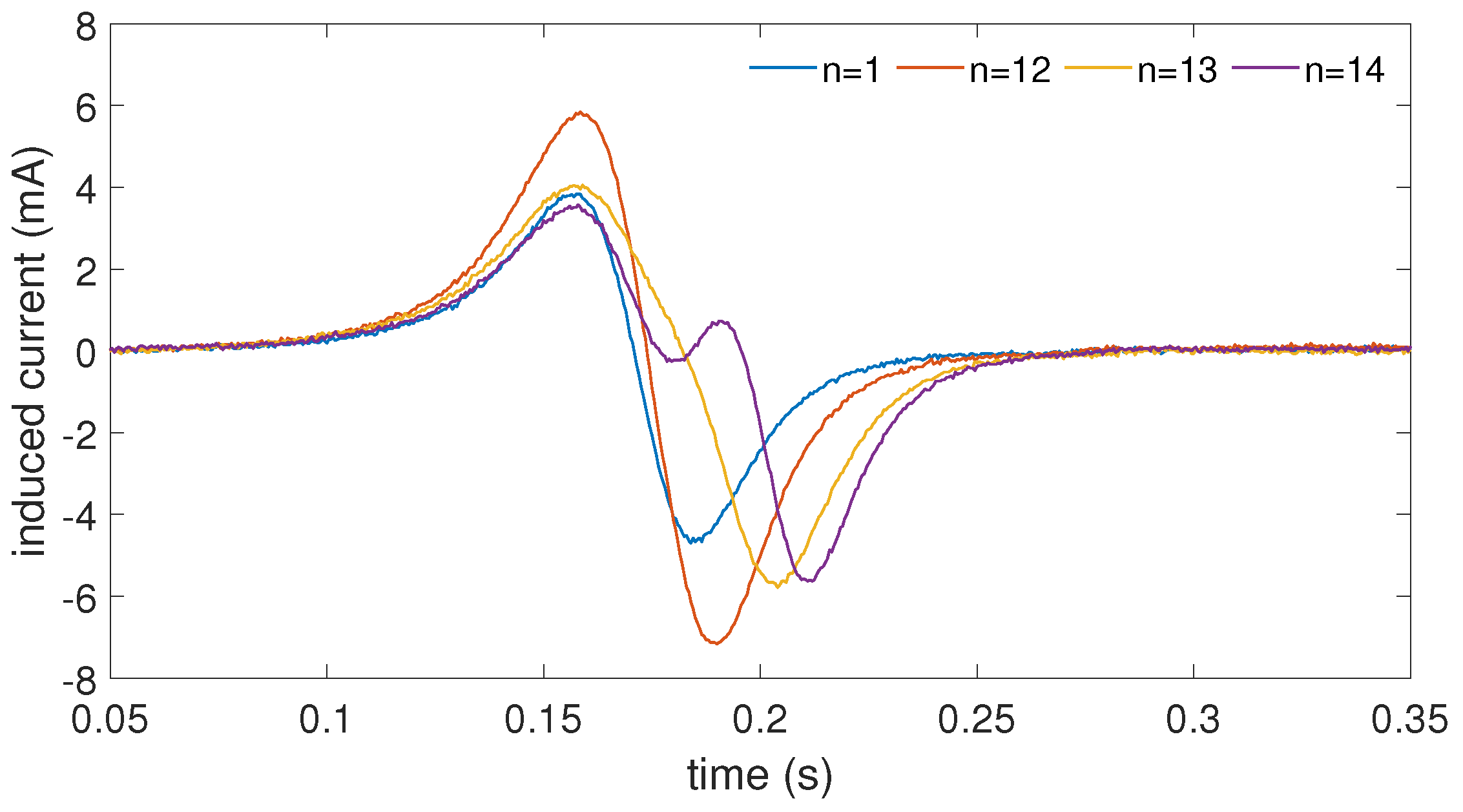
2.4. Electromechanical Coupling Determination

The crucial problem in the analysis of the electromagnetic harvester is proper EC function estimation. A simple way to determine EC is by a magnet falling through a modular coil test. In the experiments, the moving (levitating) magnet was simply dropped through the modular coil with different combinations of the active segments, and the induced current was measured using the data acquisition system shown in Figure 2. The sampling rate of the test was 2000 Hz. The magnet was released from an initial distance of 0.12 m above the coil. If the magnet contacted the cylinder wall, the test was repeated. Five tests were performed for each active coil segment. Figure 5 shows the free fall test results.
These results demonstrate that the induced current is a strongly nonlinear function depending on the active coil segments. As expected, the active segment modified the shape of the induced current, which suggests that it will modify the EC too. The highest induced current was obtained for the configuration n = 12 and equalled 7 mA. These plots are not symmetrical due to the fact that the magnet’s velocity is not constant.
In a previous study, quasi-static tests were performed. However, the maximal velocity of the magnet was much lower (0.016 m/s) than the real velocity of the harvester. Therefore, in this study, fall tests were performed.

3. Results

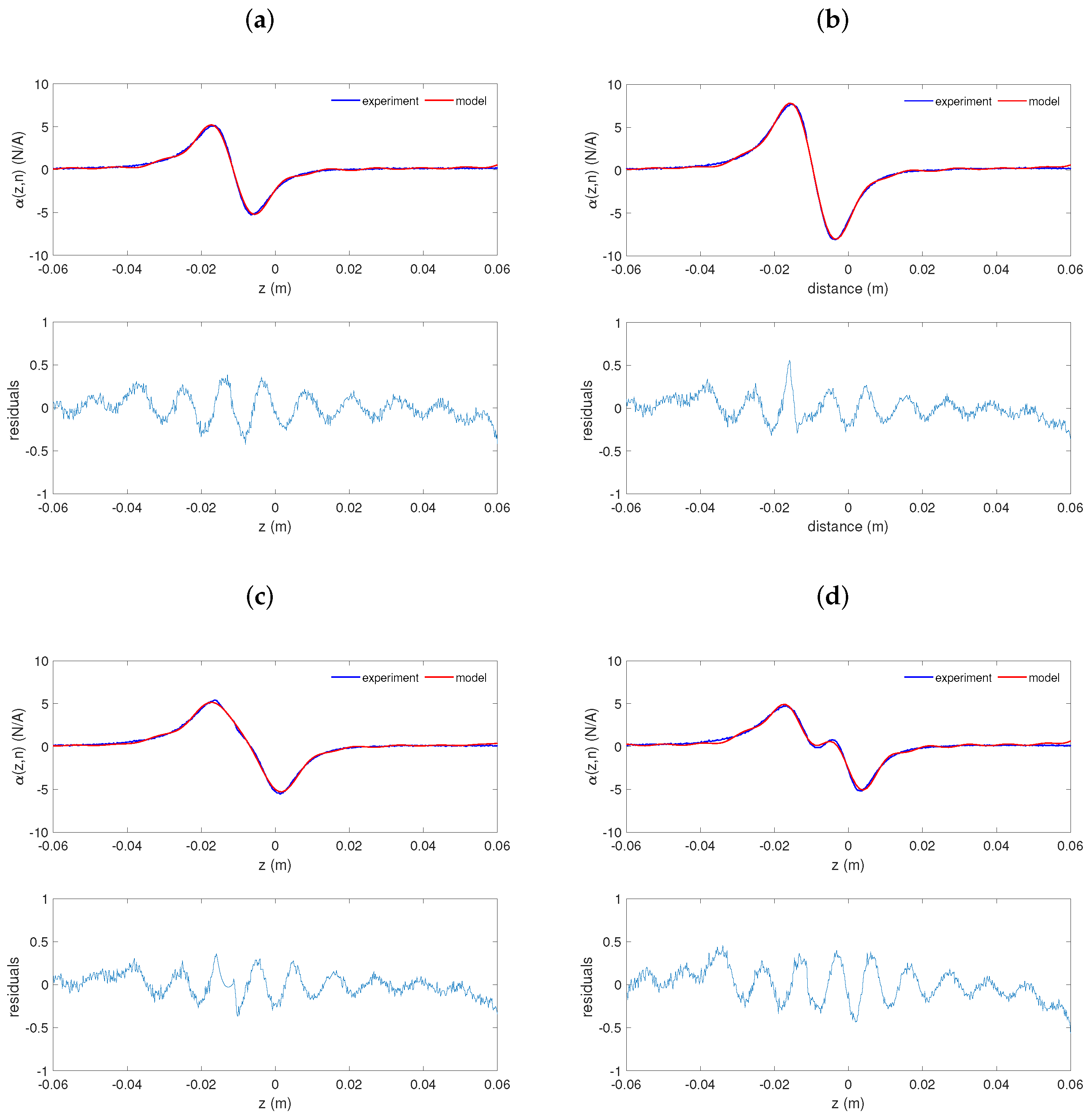
3.1. Electromechanical Coupling Modeling

As mentioned in Section 1, the EC coefficient is related to the conversion rate between electrical and mechanical energy and represents transducer efficiency. Usually, in most papers, this coefficient is assumed to have a constant value, estimated from the coil parameters.
The modification of the electromechanical models is the main goal of this analysis. First, to find the EC, one can apply Kirchhoff’s Voltage Law (Equation (2)). This gives the following relationship:
α ( z , n ) = L i ˙ ( t ) + ( R L + R C ) i ( t ) z ˙ ( t )
The signals i ( t ) and z ˙ ( t ) were measured during the experiments. The time derivative i ˙ ( t ) was numerically calculated as the first derivative of the signal i ( t ) .
Figure 6 shows the EC models and the differences between the fitted model and the experimental results (residuals). The blue line represents the experimentally determined EC and the red line denotes the fitted model. As already mentioned, the EC is a strongly nonlinear function of the magnet position and has a complex expression. The residuals (bottom figures in Figure 6a–d) describe how the mathematical models fit the data. The residuals exhibit a random distribution, which means that the proposed models fit the experiment well.
As expected, the active coil segments affect the electromechanical coupling function shape. The differences between all EC functions are quantitative and qualitative. When coil segment 1 is active, the maximal peak value of α ( z , n ) is 5 N/A and occurs close to the coil ends (Figure 6a). The distance between both peaks is around 0.01 m (similarly to the coil segment length). For the active coil segment 12, the maximum EC increases up to almost α ( z , n ) = 8 N/A and the distance between peaks is higher and equals 0.19 m (Figure 6b). When segment 13 is active, this reduction in the EC is observed ( α ( z , n ) = 5.3 N/A, Figure 6c). Interestingly, this active segment 14 causes an even greater reduction in the EC function, but two new peaks appear too (Figure 6d). This result of the EC function has not been reported yet. The shape of the electromagnetic coupling function for this configuration is interesting, and one may speculate as to the dynamics of the system.
The mathematical EC model is fitted by an eighth-order Fourier fitting formula that is easier to implement. It is represented in a trigonometric form as the sum of the sine and cosine functions describing the measured signal. The EC model has the form shown in Equation (6)
α ( z , n ) = a 0 + j = 1 8 ( a j c o s ( j w z ) + b j s i n ( j w z ) )
where a 0 and a j are constant terms associated with measured data, and w is the fundamental frequency of the proposed model. All fitting coefficients of the EC Fourier models are given in Table 2.
As shown in the residual diagrams (Figure 6) and by the goodness of fitting parameters (Table 3), the EC models are well fitted. The R-square and adjusted R-square measures are very close to 1, indicating a good fit. The root mean squared error (RMSE) and the sum of squares due to error (SSE) indicate the prediction and random error components, respectively. These parameters indicate that model 14 is the most challenging to predict.

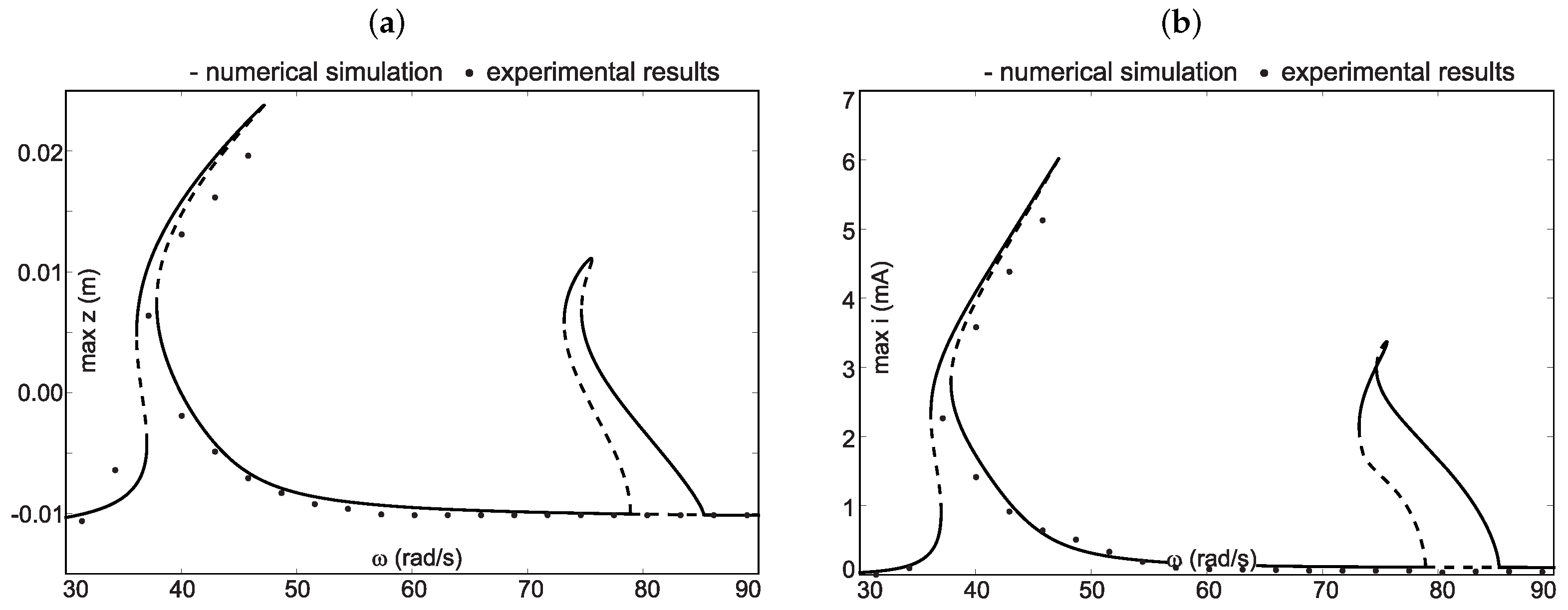
3.2. Experimental Verification

The values of the system parameters are taken from the prototype harvester: m = 0.047 kg, k = 20.4359 N/m, k 1 = 150 kN/m3, c = 0.074 Ns/m, L = 0.01 H and R = R L + R C = 1 kΩ. Experimental verification tests were performed with a fixed amplitude of 1 (mm) for the active coil segment 1. Several tests were conducted to evaluate the frequency responses.
Experimental and numerical predictions of the relative amplitude of the magnet and induced current with the frequency varied from 30 rad/s to 90 rad/s are presented in Figure 7a,b, respectively. Two resonance regions can be detected near 40 rad/s and 80 rad/s.
The solid lines mark the numerically stable solutions and the dashed curves mark the unstable ones. The dots denote the experimental results. From the experimental results, it can be seen that the main resonance peak occurs for a frequency similar to the numerical one. However, the presence of the second resonance has not been confirmed experimentally. It can also be observed that some frequencies moderately differ from the numerical predictions. This could be caused by the difference in friction modeling (constant damping coefficient) and the lack of lateral forces making the magnet rotate in the cylinder (nonlinear friction force). Moreover, this region is narrow; therefore, a slight change in the magnet’s dynamics or parameter identification caused its full reduction. It should be noted that the mathematical model assumed no leakage of flux, which also led to some discrepancies.
It is worth noting that the peak values of the experimental results are lower than the simulation results. The maximal induced current at the first resonant frequency reaches approximately 6 mA, which is significantly higher than the value at the second resonant frequency (about 3.5 mA). Similar results were observed for the magnet frequency response. In general, the first resonant frequency and the amplitudes measured from the shaker tests are close to the numerical frequency responses.

4. Electromechanical Coupling Discussion

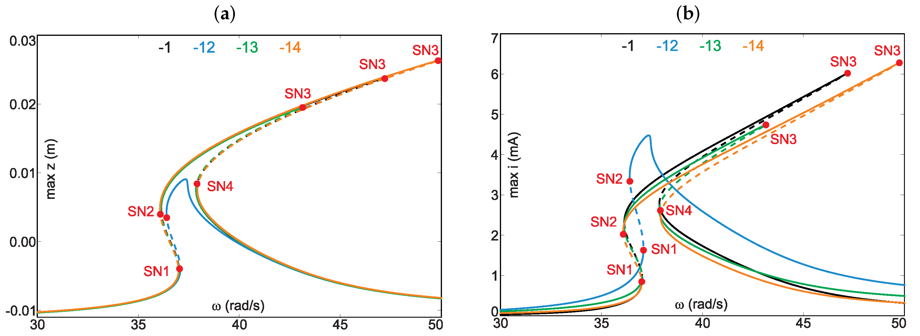
4.1. Frequency Response Analysis

One of the benefits of the modular coil is that it allows the simple modification of the EC function. Figure 8 shows the effect of changing the active coil segments. For each set of the coil segments, simulations were performed in the frequency range from 30 rad/s to 50 rad/s. The system response for the active segment 1 is denoted by the black line, the blue line shows the results for the active module 12, the green line for 13, and the orange line for 14. The S N 1 , …, S N 4 denote the saddle-node (fold) bifurcation points.
For configurations 1, 13 and 14, the nonlinear effect and multistability are observed. For these configurations, two unstable branches (four SN bifurcations) occur. From these plots, it can be observed that the active coil segment influences the increase in the resonance bandwidth. Interestingly, for configuration 12, the system response is weakly nonlinear, and the maximal magnet’s displacement is 0.01 m, but the induced current in the peak resonance is 4.5 mA. The highest maximal magnet response and the highest induced current are observed for the active segment 14.
Figure 9 shows a similar analysis performed for the second resonance region. Motion in this region is caused by period-doubling bifurcation (PD). This means the creation of a periodic orbit with a double period of the original orbit. However, in this case, configuration 12 shows the highest induced current of 4.4 mA. It is important to mention that the second resonance bandwidth region is not dependent on the active coil segment. The induced currents and magnet displacements are very similar for configurations 1, 13 and 14.
In summary, it can be stated that changing the active coil segment influences the magnet’s dynamics and recovered current, especially in the first resonance region. Configuration 12 differs the most from the others. This is probably the result of a higher maximal peak value of the electromechanical coupling (Figure 6b).

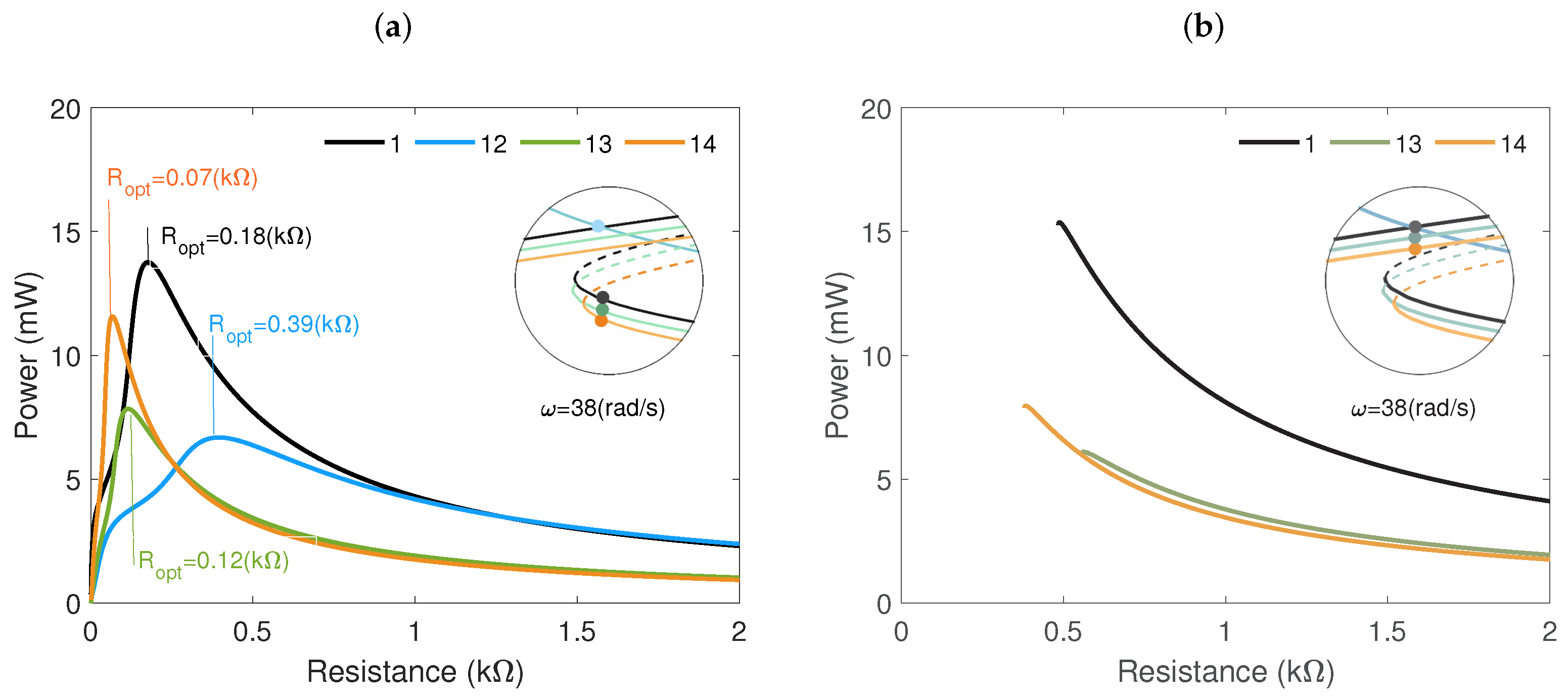
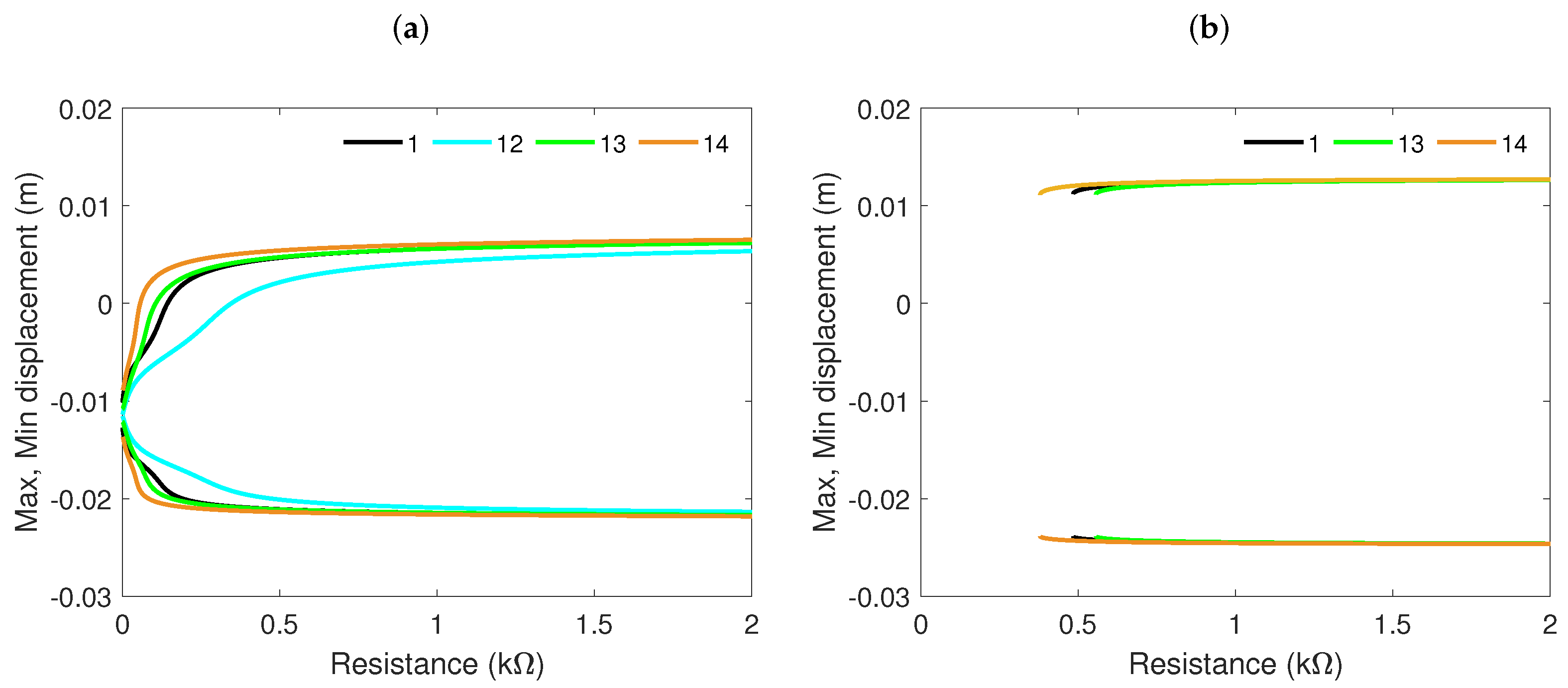
4.2. Influence of Resistance

Figure 10 shows the output power of the electromagnetic harvester as a function of resistance for a frequency of 38 rad/s. Figure 10a shows the result for the solution represented by the bottom branch, while Figure 10b shows the result for the top branch. With increasing load resistance, the output power increases sharply first and then decreases gradually.
For coil configuration 1 and the solution represented by the bottom branch (Figure 10a), the maximum power is 14 mW at the optimum resistance of 0.18 kΩ. In comparison, for configuration 12, the maximum power is approximately 7 mW for a resistance of 0.39 kΩ; for configuration 13, the power equals 8 mW for optimum resistance of 0.12 kΩ; and for configuration 14, the obtained power is 11.5 mW for the load resistance of 0.07 kΩ. The next diagram (Figure 10b) presents the results of the solution from the top branch. It can be observed that with increasing resistance, the output power decreases gradually.
Figure 11a,b show the maximal and minimal displacement of the levitating magnet versus resistance. After comparing both diagrams, it can be concluded that resistance does not influence the magnet’s displacement represented by the top branch (Figure 11b). For the bottom branch (Figure 11a), the resistance effect is visible for resistance lower than 0.5 kΩ.
To sum up, the active coil module influences the recovered power. It can also be seen that the active coil segment controls the optimal resistance. A low resistance value means that the solution represented by the top branch (and multistability) disappears. Therefore, in the next section, the problem of the multistability region is investigated.

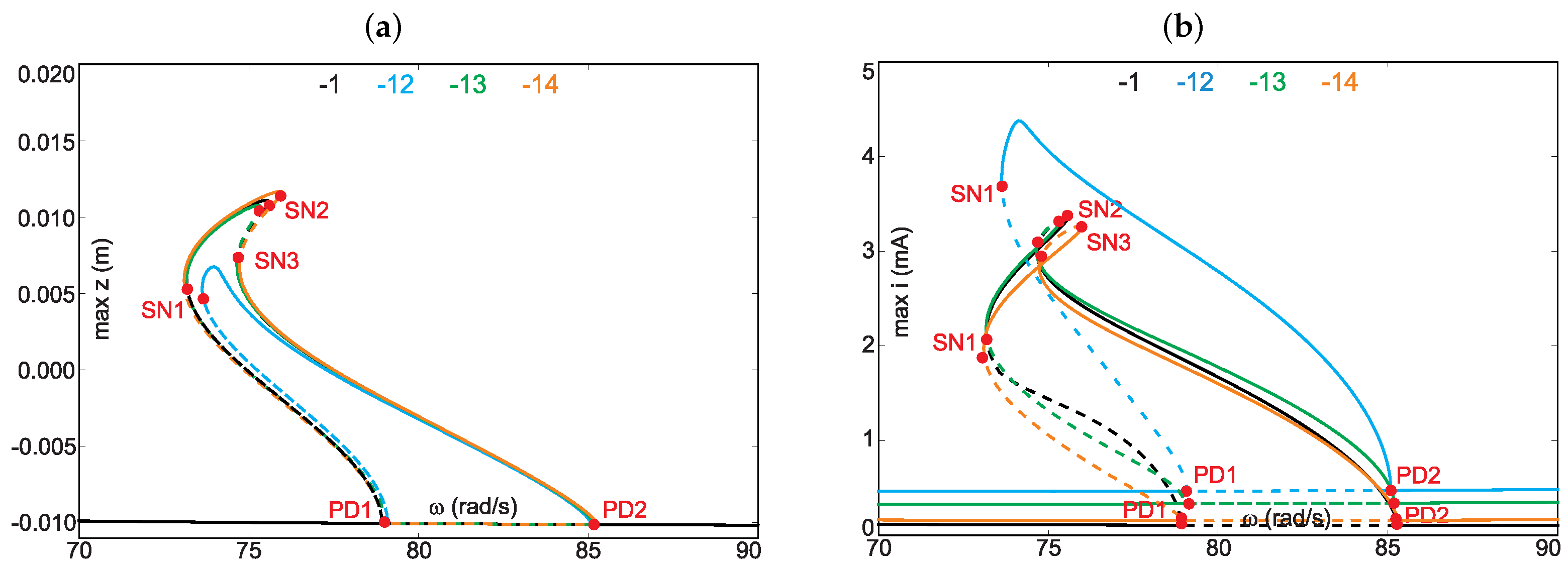
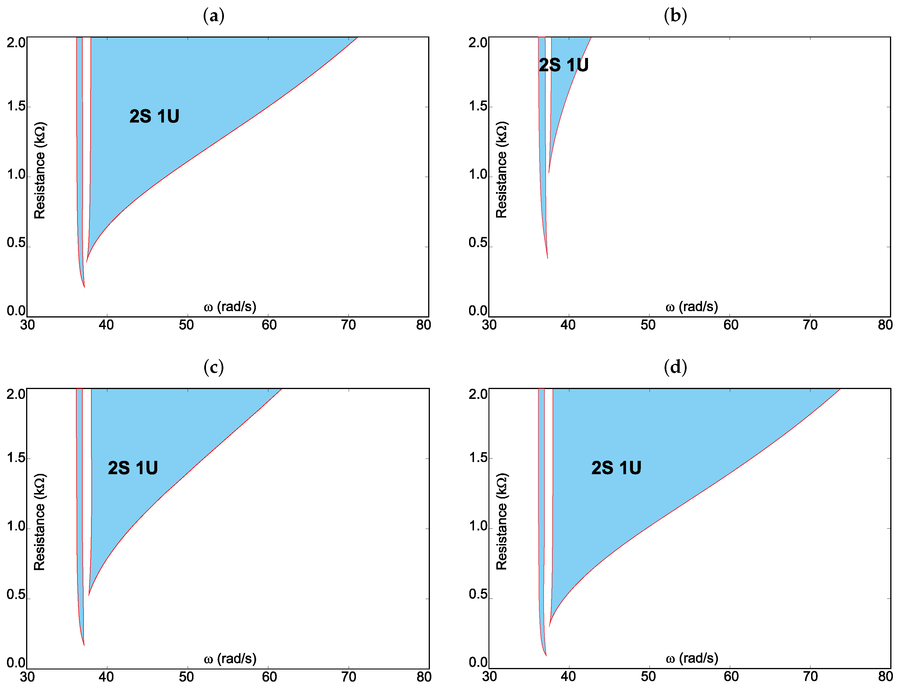
4.3. Foldover Effect Analysis

The foldover effect is defined as the bending of the resonance peak. This effect is an important feature of the investigated harvester because it produces two or more solutions. One of the solutions is characterized by higher energy input.
Figure 12 presents the foldover (multistability) region (blue area) in a two-dimensional space ( ω , R). The red solid curve marks the border of multistability. Panel (a) shows the results for the active coil segment 1, panel (b) corresponds to segment 12, panel (c) for segment 14, and finally panel (d) gives the results for segment 14. In the foldover region, two stable (2S) and one unstable (1U) solutions occur. These solutions depend on the initial conditions of the magnet.
Comparison of all results demonstrates that the active coil segments influence the foldover effect. The widest region can be observed for configuration 14, while for segment 12, the region with the foldover effect is the narrowest. It is worth noting that the foldover region occurring from the left side of the resonance curve (thin strip close to 38 rad/s) does not depend on the coil’s segment.

5. Conclusions

This paper presented a complex numerical and experimental analysis of the dynamics and energy recovery of a magnetic levitation harvester. The harvester had a specially designed module coil, which allowed for easy configuration of the electromechanical coupling. First, the nonlinear models of the electromechanical coupling were determined via fall tests. These models were estimated for different configurations of the active coil segments. The results revealed that the electromechanical coupling affected the magnet’s dynamics as well as energy harvesting, especially in the main resonance region. In the second resonance region, only coil configuration 12 showed significant differences. The proper configuration of the coil made it possible to expand the resonance bandwidth and increase energy harvesting. The obtained results confirmed the nonlinear resonance and multistability in this harvester. Two foldover effects on both sides of the resonance curve were observed.
The analysis of resistance influence demonstrated that higher recovered power could be observed for the classical configuration 1. However, it is worth noting that the modular coil allows for a shift in optimal resistance and thus can improve the foldover effect. Interestingly, too, it was observed that configuration 12 exhibited the smallest area with multistability. This is caused by a higher peak value of the electromechanical coupling (electrical damping). The results allow us to conclude that the length of the coil (and magnet) should be optimized to increase energy harvesting.
The experimental results obtained with the shaker–harvester system confirmed the presence of only the first resonance. Unfortunately, the second resonance region was not confirmed experimentally. This is probably due to the model’s simplifications. The maximum power obtained from the experiment was 25 mW, while that from the numerical simulation was 36 mW. According to the results, the proposed harvester can generate great power at a low frequency.
These results provide a strong foundation for developing such harvesters and show their tremendous application potential. In the future, the electromechanical coupling will be modified by using different shapes of coils (C-shape, L-shape) and different magnets (rings, square and magnet-separator construction), as well as by using additional magnets.

6. Patents

The result of the work is a Polish patent: “Device for measuring magnetic forces, especially between cylindrical magnets”, no. P.438043 (Figure 4a).

Funding

This research was financed in the framework of the project Theoretical–experimental analysis possibility of electromechanical coupling shaping in energy harvesting systems no. DEC-2019/35/B/ST8/01068, funded by the National Science Centre, Poland.

Data Availability Statement

Not applicable.

Conflicts of Interest

The author declares no conflict of interest.

References

  1. Ghazanfarian, J.; Mohammadi, M.M.; Uchino, K. Piezoelectric Energy Harvesting: A Systematic Review of Reviews. Actuators 2021, 10, 312. [Google Scholar] [CrossRef]
  2. Ibrahim, P.; Arafa, M.; Anis, Y. An Electromagnetic Vibration Energy Harvester with a Tunable Mass Moment of Inertia. Sensors 2021, 21, 5611. [Google Scholar] [CrossRef] [PubMed]
  3. Iannacci, J. Microsystem based Energy Harvesting (EH-MEMS): Powering pervasivity of the Internet of Things (IoT)—A review with focus on mechanical vibrations. J. King Saud Univ.-Sci. 2019, 31, 66–74. [Google Scholar] [CrossRef]
  4. Kecik, K.; Kowalczuk, M. Effect of Nonlinear Electromechanical Coupling in Magnetic Levitation Energy Harvester. Energies 2021, 14, 2715. [Google Scholar] [CrossRef]
  5. Tang, X.; Lin, T.; Zuo, L. Design and Optimization of a Tubular Linear Electromagnetic Vibration Energy Harvester. IEEE/ASME Trans. Mechatron. 2014, 19, 615–622. [Google Scholar] [CrossRef]
  6. Glynne-Jones, P.; Tudor, M.; Beeby, S.; White, N. An electromagnetic, vibration-powered generator for intelligent sensor systems. Sens. Actuators A Phys. 2004, 110, 344–349. [Google Scholar] [CrossRef] [Green Version]
  7. Foong, F.M.; Thein, C.K.; Ooi, B.L.; Yurchenko, D. Increased power output of an electromagnetic vibration energy harvester through anti-phase resonance. Mech. Syst. Signal Process. 2019, 116, 129–145. [Google Scholar] [CrossRef]
  8. Nguyen, H.T.; Genov, D.; Bardaweel, H. Mono-stable and bi-stable magnetic spring based vibration energy harvesting systems subject to harmonic excitation: Dynamic modeling and experimental verification. Mech. Syst. Signal Process. 2019, 134, 106361. [Google Scholar] [CrossRef]
  9. Gratuze, M.; Alameh, A.H.; Nabki, F. Design of the Squared Daisy: A Multi-Mode Energy Harvester, with Reduced Variability and a Non-Linear Frequency Response. Sensors 2019, 19, 3247. [Google Scholar] [CrossRef] [Green Version]
  10. Kecik, K.; Mitura, A. Energy recovery from a pendulum tuned mass damper with two independent harvesting sources. Int. J. Mech. Sci. 2020, 174, 105568. [Google Scholar] [CrossRef]
  11. Wei, C.; Jing, X. A comprehensive review on vibration energy harvesting: Modelling and realization. Renew. Sustain. Energy Rev. 2017, 74, 1–18. [Google Scholar] [CrossRef]
  12. Yang, X.; Wang, C.; Lai, S. A magnetic levitation-based tristable hybrid energy harvester for scavenging energy from low-frequency structural vibration. Eng. Struct. 2020, 221, 110789. [Google Scholar] [CrossRef]
  13. Carneiro, P.; Soares dos Santos, M.P.; Rodrigues, A.; Ferreira, J.A.; Simões, J.A.; Marques, A.T.; Kholkin, A.L. Electromagnetic energy harvesting using magnetic levitation architectures: A review. Appl. Energy 2020, 260, 114191. [Google Scholar] [CrossRef] [Green Version]
  14. Wang, W.; Cao, J.; Zhang, N.; Lin, J.; Liao, W.H. Magnetic-spring based energy harvesting from human motions: Design, modeling and experiments. Energy Convers. Manag. 2017, 132, 189–197. [Google Scholar] [CrossRef]
  15. Munaz, A.; Lee, B.C.; Chung, G.S. A study of an electromagnetic energy harvester using multi-pole magnet. Sens. Actuators A Phys. 2013, 201, 134–140. [Google Scholar] [CrossRef]
  16. Masoumi, M.; Wang, Y. Repulsive magnetic levitation-based ocean wave energy harvester with variable resonance: Modeling, simulation and experiment. J. Sound Vib. 2016, 381, 192–205. [Google Scholar] [CrossRef] [Green Version]
  17. Saha, C.; O’Donnell, T.; Wang, N.; McCloskey, P. Electromagnetic generator for harvesting energy from human motion. Sens. Actuators A Phys. 2008, 147, 248–253. [Google Scholar] [CrossRef]
  18. Saravia, C.M. A formulation for modeling levitation based vibration energy harvesters undergoing finite motion. Mech. Syst. Signal Process. 2019, 117, 862–878. [Google Scholar] [CrossRef]
  19. Mann, B.; Sims, N. Energy harvesting from the nonlinear oscillations of magnetic levitation. J. Sound Vib. 2009, 319, 515–530. [Google Scholar] [CrossRef] [Green Version]
  20. Morais, R.; Silva, N.M.; Santos, P.M.; Frias, C.M.; Ferreira, J.A.; Ramos, A.M.; Simões, J.A.; Baptista, J.M.; Reis, M.C. Double permanent magnet vibration power generator for smart hip prosthesis. Sens. Actuators A Phys. 2011, 172, 259–268. [Google Scholar] [CrossRef]
  21. Apo, D.J.; Priya, S. High Power Density Levitation-Induced Vibration Energy Harvester. Energy Harvest. Syst. 2014, 1, 79–88. [Google Scholar] [CrossRef]
  22. Saravia, C.M.; Ramírez, J.M.; Gatti, C.D. A hybrid numerical-analytical approach for modeling levitation based vibration energy harvesters. Sens. Actuators A Phys. 2017, 257, 20–29. [Google Scholar] [CrossRef]
  23. Foisal, A.R.M.; Hong, C.; Chung, G.S. Multi-frequency electromagnetic energy harvester using a magnetic spring cantilever. Sens. Actuators A Phys. 2012, 182, 106–113. [Google Scholar] [CrossRef]
  24. Kecik, K.; Mitura, A.; Lenci, S.; Warminski, J. Energy harvesting from a magnetic levitation system. Int. J. Non-Linear Mech. 2017, 94, 200–206. [Google Scholar] [CrossRef]
  25. Kecik, K. Architecture and Optimization of a Low-Frequency Maglev Energy Harvester. Int. J. Non-Linear Mech. 2019, 19, 1950097. [Google Scholar] [CrossRef]
  26. Constantinou, P.; Mellor, P.; Wilcox, P. A magnetically sprung generator for energy harvesting applications. IEEE/ASME Trans. Mechatron. 2012, 17, 415–424. [Google Scholar] [CrossRef]
  27. Berdy, D.; Valentino, D.; Peroulis, D. Design and optimization of a magnetically sprung block magnet vibration energy harvester. Sens. Actuators A Phys. 2014, 218, 69–79. [Google Scholar] [CrossRef]
  28. Avila Bernal, A.; Linares García, L. The modelling of an electromagnetic energy harvesting architecture. Appl. Math. Model. 2012, 36, 4728–4741. [Google Scholar] [CrossRef]
  29. Soares dos Santos, M.P.; Ferreira, J.A.F.; Simões, J.A.O.; Pascoal, R.; Torrão, J.; Xue, X.; Furlani, E.P. Magnetic levitation-based electromagnetic energy harvesting: A semi-analytical non-linear model for energy transduction. Sci. Rep. 2016, 6, 2045–2322. [Google Scholar] [CrossRef]
  30. Mösch, M.; Fischerauer, G. A Comparison of Methods to Measure the Coupling Coefficient of Electromagnetic Vibration Energy Harvesters. Micromachines 2019, 10, 826. [Google Scholar] [CrossRef] [Green Version]
  31. Donoso, G.; Ladera, C.; Martin, P. Magnet fall inside a conductive pipe: Motion and the role of the pipe wall thickness. Eur. J. Phys. 2009, 30, 855–869. [Google Scholar] [CrossRef]
  32. Sneller, A.; Mann, B. On the nonlinear electromagnetic coupling between a coil and an oscillating magnet. J. Phys. D Appl. Phys. 2010, 43, 295005. [Google Scholar] [CrossRef]
  33. Cannarella, J.; Selvaggi, J.; Salon, S.; Tichy, J.; Borca-Tasciuc, D.A. Coupling Factor between the Magnetic and Mechanical Energy Domains in Electromagnetic Power Harvesting Applications. IEEE Trans. Magn. 2011, 47, 2076–2080. [Google Scholar] [CrossRef]
  34. Jensen, T.W.; Insinga, A.R.; Ehlers, J.C.; Bjørk, R. The full phase space dynamics of a magnetically levitated electromagnetic vibration harvester. Sci. Rep. 2021, 11, 2045–2322. [Google Scholar] [CrossRef] [PubMed]
  35. Saravia, C.M. On the electromechanical coupling in electromagnetic vibration energy harvesters. Mech. Syst. Signal Process. 2020, 136, 106027. [Google Scholar] [CrossRef]
  36. Kecik, K.; Kapitaniak, M. Parametric analysis of magnetorheologically damped pendulum vibration absorber. Int. J. Struct. Stab. Dyn. 2014, 14, 1440015. [Google Scholar] [CrossRef]
  37. Kecik, K. Dynamics and control of an active pendulum system. Int. J. Non-Linear Mech. 2015, 70, 63–72. [Google Scholar] [CrossRef]
Figure 1. Photo (a) and scheme (b) of the prototype electromagnetic harvester with a modular coil. Each segment of the modular coil can be activated independently.
Energies 15 04007 g001
Figure 2. Scheme of the experimental setup with the prototype harvester.
Energies 15 04007 g002
Figure 3. Mechanical model (a) and a coupled electromechanical model representation of the electromagnetic vibration transducer (b).
Energies 15 04007 g003
Figure 4. Photo of the magnetic force measurement setup (a) and a magnetic repulsion force vs. moving magnet displacement curve (b).
Energies 15 04007 g004
Figure 5. Induced current obtained from a single magnet falling through a coil.
Energies 15 04007 g005
Figure 6. Electromechanical coupling function and residuals for different configurations of the modular coil: active segment 1 (a), active segment 12 (b), active segment 13 (c) and active segment 14 (d).
Energies 15 04007 g006
Figure 7. Comparison of the magnet’s response (a) and output induced current (b) versus excitation frequencies obtained from the simulation model and experiments.
Energies 15 04007 g007
Figure 8. Comparison of frequency responses of the maximal magnet displacement (a) and the maximal induced current (b) when the active coil module is changed. The analysis was performed near the main resonance. The SN point denotes saddle-node bifurcation.
Energies 15 04007 g008
Figure 9. Comparison of the frequency response of the maximum magnet displacement (a) and the maximal induced current (b) when the active coil module is changed. The analysis was performed in the second resonance. The SN point denotes saddle-node bifurcation.
Energies 15 04007 g009
Figure 10. Output power was obtained for the solution from the bottom (a) and top (b) branches and a frequency of 38 rad/s. The power was calculated from equation P = m a x ( i 2 ( t ) ) R .
Energies 15 04007 g010
Figure 11. Maximal and minimal displacement of the magnet as a function of resistance, for the solution from the bottom (a) and top (b) branch and a frequency of 38 rad/s.
Energies 15 04007 g011
Figure 12. Bifurcation diagram of a two-parameter space. The blue region shows the foldover region. Panel (a) shows the result for active segment 1, panel (b) for active segment 12, panel (c) for segment 13 and panel (d) for segment 14.
Energies 15 04007 g012
Table 1. Modular coil parameters.
ParametersModule 1Module 2Module 3Module 4
Wire diameter (mm)0.140.140.140.14
Number of turns (−)1800180018001800
Resistance (Ω)330330330330
Inductance (H)0.250.250.250.25
Table 2. Coefficients of the Fourier EC models.
n a 0 a 1 b 1 a 2 b 2 a 3 b 3 a 4 b 4
10.1514−0.8818−0.915−1.651−0.0038−1.0451.013−0.08391.072
120.1907−1.279−1.652−2.592−0.6408−2.0940.8981−0.88611.356
130.2163−0.7958−1.632−1.769−1.087−1.415−0.1359−0.7180.1624
140.2426−0.7538−1.599−1.49−1.028−0.876−0.1482−0.0785−0.1259
n a 5 b 5 a 6 b 6 a 7 b 7 a 8 b 8 w
10.42960.59790.4910.09280.2442−0.13620066.57
12−0.02081.0420.37050.52640.28440.12710066.66
13−0.22580.0835−0.0586−0.0992−0.1312−0.1678−0.1303−0.091463.81
140.2122−0.37350.1808−0.50320.0094−0.5009−0.0939−0.307467.63
Table 3. Goodness of fit of the EC models.
nR-SquareAdj R-SquareRMSESSE
10.99360.99350.148013.69
120.99750.99740.146213.36
130.99600.99590.131910.84
140.98890.98860.189922.46
Publisher’s Note: MDPI stays neutral with regard to jurisdictional claims in published maps and institutional affiliations.

