Article

Spiral Groove Parametric Study of Solid Particles Deposition Characteristics in Sealing Lubrication Film

School of Energy and Power Engineering, Jiangsu University, Zhenjiang 212013, China
*
Author to whom correspondence should be addressed.
Energies 2022, 15(11), 3893; https://doi.org/10.3390/en15113893
Submission received: 4 April 2022 / Revised: 17 May 2022 / Accepted: 23 May 2022 / Published: 25 May 2022

Abstract

:
In order to study the effect of groove parameters on solid particles’ deposition in mechanical face seal lubrication film, a multi-phase flow calculation model for the sealing micro-gap lubricating film was established based on the Laminar model, mixture multi-phase flow model, Zwart–Gerber–Belamri cavitation model, and DPM model in Fluent, and a numerical simulation of the effect of groove parameters is presented. The results show that, with the increase of groove depth, the circumferential sedimentary zone in the dam area decreases or even disappears, and the groove area becomes the main sedimentary part; the particle deposition rate decreases first and then increases with the increase of groove depth and spiral angle. The influence of groove depth on the deposition rate at low speed is more significant than that at high speed. The increase of deposition rate caused by a spiral angle that is too large is greater than that caused by a spiral angle that is too small. The optimal groove depth and spiral angle are around 6 µm and 18°, respectively; when the rotating speed is 1000 rpm, the deposition rate increases obviously with the increase of the groove diameter ratio; meanwhile, when the rotating speed increases to more than 2000 rpm, the deposition rate increases first and then decreases with the increase of the groove diameter ratio. When the groove diameter ratio is about 0.5, the deposition rate is the largest. For example, when the rotating speed is 2000 rpm, the deposition rate of the groove diameter ratio, 0.5, is about 200% higher than that of groove diameter ratio, 0.2. The lower the speed, the more sensitive the deposition rate is to the groove diameter ratio. The sensitivity at 1000 rpm is 14 times that at 5000 rpm. The deposition rate increases with the increase of the groove width ratio. The higher the rotating speed, the smaller the rate of deposition rate increase. However, when the rotating speed is 5000 rpm and the groove width ratio is higher than 0.7, the deposition rate increases sharply.

1. Introduction

The liquid seal is a kind of non-contacting dynamic seal that is used for the sealing of rotating shafts. It utilizes pumping and the hydrodynamic effect generated by micro modeling spiral grooves on the sealing face to minimize leakage and strengthen film pressure. This technical solution allows us to reduce asperity contact, wear, and friction during operation. With its high stability and low maintenance, the liquid seal has been extensively studied and applied to petroleum and chemical industries [1].
In the practical application of hydrodynamic mechanical seals, the failure of the blocking phenomenon of the spiral groove often occurs. It is caused by the deposition of tiny solid particles in the grooves, such as low-pressure particle suction, entrainment of sealing medium, and end face wear. When addressing the problem of multi-phase flow in the micro-gap of mechanical seal, our main research work studied the gas–liquid and liquid–solid two-phase flow.
The recent research about multi-phase flow in mechanical seal gap concentrates on gas–liquid two-phase flow in lubrication film. Cavitation occurs during face seal operation and affects the film pressure distribution. Relevant works were performed by Findley [2] and Wenbin Gao [3]. Through the analysis of film pressure, it was observed that cavitation develops in the low-pressure zone. At the same time, the high-pressure zone will move toward the outer diameter side of the sealing ring because of cavitation. Zhentao Li, Muming Hao, et al. [4,5,6], based on JFO cavitation boundary met with law of conservation of mass, analyzed the influence of spiral groove structural parameters, microscopic surface waviness, taper, and roughness on liquid lubricated mechanical seals. They pointed out that a rougher and more complex end face raises the possibility of cavitation. Chen H.L. et al. [7,8] studied cavitation locations of mechanical face seals. They presented that cavitation is apt to generate inside or near the grooves and cavities. A more specific work about positioning cavitation was performed by Xuezhong Ma, Xiangkai Meng et al. [9]. In their study, cavitation zone tends to draw closer to the inner diameter side of the sealing ring than that of non-reverse spiral groove.
However, research on liquid–solid two-phase flow in lubrication film is relatively scarce. Based on fluent multi-phase flow cavitation model, Jihua et al. [10] studied the leakage rate and opening force of equilateral triangular microporous end face mechanical seal for equilateral triangular microporous end face mechanical seals. The research showed that increasing the rotating speed will strengthen the change trend of the leakage rate. Xu Xiaodong et al. [11] analyzed the influence of structural parameters on liquid film evaporation characteristics and sealing performance. The results show that the opening force decreases with the increase of spiral angle, groove diameter ratio, and groove depth. However, the presence of solid particles was not considered in this study. Zhao Dongyi et al. [12] studied the bearing capacity and solid volume fraction distribution of the lubricating film when the particle properties of the self-lubricating material are different. The research results show that, when the self-lubricating bearing is in the dry friction state, if the bearing speed is high, the particle volume fraction of the self-lubricating material is large, and the particle diameter is small, a larger bearing capacity of the lubricating film can be obtained. The effects of the main structural parameters on the mechanical seal have been studied by Su Wen-Tao, Li Yang, et al. [13], including the film thickness, taper, dam-width ratio, and waviness amplitude. The numerical results showed that the increase of base film thickness will increase the leakage rate and decrease the opening force. Xudong Peng et al. [14] took mechanical face seal with a U-shaped groove as the target, and the wear problem of the sealing face caused by impurity particles in the medium was studied. It also turns out that the opening force, leakage rate, and the ratio of stiffness to leakage all increase approximately linearly with the number of wear marks at the groove roots. Yan Yan et al. [15] studied a bidirectional self-pumping fluid static mechanical seal with a drainage hole in a moving ring and found that this new mechanical seal had good anti-particle interference. On the basis of that, Qun Chen et al. [16], via numerical simulation, found the self-cleaning properties under several conditions, including different solid particle diameters, rotational speed, pressure, lubrication film thickness, and solids volume. Huilong Chen, Muzi Zuo, et al. [17] used the mixture model to study the solid–liquid two-phase flow characteristics of mechanical face seal lubrication film and obtained the distribution law of tiny solid particles inside the seal end face lubrication film and its influence on seal performance. They found that particle deposition weakened the hydrodynamic effect and film stiffness. When considering both domestic and foreign research, we see that there are few studies on gas–liquid–solid flow characteristics in the sealing gap of mechanical seals. Although some progress has been made in the study of the movement characteristics and distribution of solid particles in the lubrication film, it is still not in-depth.
It can be seen that, although the research on the gas–liquid–solid multi-phase flow of micro-gap lubricating film on the end face of hydrodynamic mechanical seal has made preliminary progress, it is still not systematic and in-depth, especially the movement and deposition characteristics of solid particles in micro-gap lubricating film, and their influence on the sealing lubrication performance have not been clearly studied. Therefore, this study took the liquid lubricated hydrodynamic mechanical seal as the research object, established the multi-phase flow calculation model of the sealing micro-gap lubrication film, and studied the movement and deposition characteristics of solid particles in the lubrication film and their influence on the sealing lubrication performance, so as to provide a theoretical reference for the design of liquid end seal with excellent performance.

2. Mathematical Model

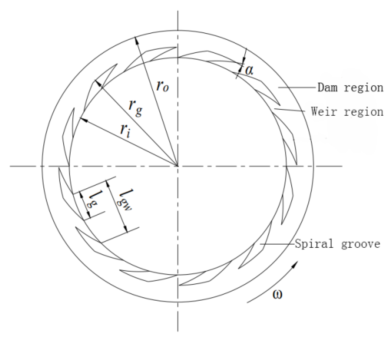
2.1. Geometric Model

The geometric model of rotational ring of the mechanical face seal is illustrated in Figure 1. The groove shape is a logarithmic spiral presented in Equation (1) [18]:
r = r i e φ tan α
where r i , α , and φ are spiral groove inner radius, spiral angle, and spiral expansion angle, respectively; and r s and r 0 are the spiral groove outer root radius and radius of sealing ring, respectively. The ratio of the groove zone radial width to seal end face radial width is defined as the groove diameter ratio, β ; and the groove width ratio, γ , was defined by the ratio of circumferential width of slot area at the same radius, l s , to circumferential width of grooved weir area, l g w . Corresponding values of aforesaid geometrical parameters are shown in Table 1.
The modeling of the lubrication film is shown in Figure 2.

2.2. Assumptions

The continuous phase inside seal gap is pure water. The density of the discrete phase solid particles is 3450 kg/m3, and the viscosity is 0.04 Pa·s [19]. The average particle diameter is 3 µm, and the particle inlet volume fraction is 10%. For reducing the complexity of the calculation, the following assumptions are made:
The lubrication film medium and solid particle temperature remain stable; it stays at 25 °C, regardless of vaporization, viscosity shift, and thermal radiation. There is no slip between the lubrication film and the solid boundary of sealing rings, regardless of roughness. Solid particles are treated as uniform spheres in size [20,21]. The Brownian and hot swimming forces of the particles and the additional mass forces of the internal flows, Coriolis forces, Magnus lift forces, Saffman forces, and Basset forces are ignored. Assuming that there is even distribution at the inner radius, the particles’ injection velocity is zero, their mass flow rate is 1 × 10⁻⁶ kg/s, and the release period is set at 0~0.1 s. In this paper, the bidirectional coupling between the continuous and discrete phase is also considered. The outer diameter side and inner diameter side of the lubrication film were defined as the escape boundary, and the collision of solid particles was completely elastic, with a rebound coefficient of 1.

2.3. Numerical Model

2.3.1. DPM Model

There are mainly two current computation models of gas–liquid–solid multi-phase flow: one of them is Euler–Euler method, which is based on the double-fluid model; and the other is the Euler–Lagrange method-based particle fluid association model, and DPM model belongs to the later. The DPM model assumes that the discrete phase is sparse enough.
Particulate loading, β, is the mass density ratio of the discrete phase and continuous phase:
λ = α d ρ d α c ρ c
The density ratio of the discrete and continuous phase is as follows:
ω = ρ d ρ c
where α d and α c are volume fraction of discrete phase and continuous phase, respectively; and ρ d and ρ c are density of discrete phase and continuous phase, respectively.
Thus, the average distance of discrete phase particle is obtained as follows:
L d d = ( π 6 × 1 + κ κ ) 1 / 3
where d d is the particle diameter of the discrete phase, and κ = λ ω = α d α c .
The discrete volume fraction is usually 10~12% [22]. The DPM model is chosen because the volume ratio of the discrete phase is quite small, and the CV (control volume) of discrete phase is actually not too much less than the flow field scale.

2.3.2. Cavitation Model

The multi-phase flow cavitation model Zwart–Gerber–Belamri (ZGB) discussed by Zwart et al. was derived from the full cavitation model by Singhal et al. [23,24,25]. The distinctions between the two models are the expression of growth and collapse of the vapor bubbles. The full cavitation model considers the impact of comprehensible gas, while the ZGB model considers the nucleation on account of better convergence speed and stability, so the governing equation was as follows:
  • Continuity equation:
    ρ m t + x i ( ρ m ν m i ) = 0
  • Momentum equation:
    t ( ρ m ν m i ) + ν m i ( ρ m ν m i ) x j = p x i + μ m x j ( ν m i x j + ν m j x i )
  • Vapor transport equation:
    t ( α ρ ν ) + x i ( α ρ ν ν ν ) = R e R c
    where ρ m is the mixture density; ρ m = n = 1 2 α ρ n ; ν m is the mass-averaged velocity; ν m =   n = 1 2 α n ρ n ν n / ρ m ; ρ n , ν n , and α n are the density, velocity, and volume fraction of phase n, respectively; μ m is the viscosity of the mixture; and μ m = n 2 α n μ n . In the equations, the slip velocity for vapor phase was ignored. In the equations, ν is the vapor phase; α is the vapor volume fraction; and R e and R c are mass transfer source terms connected to the growth and collapse of the vapor bubbles, respectively, which are described as follows:
    If   p p ν ,   R e = F v a p 3 α n u c ( 1 α ν ) ρ ν N B 2 3 p ν p ρ l ,
    If   p p ν ,   R c = F c o n d 3 α ν ρ ν N B 2 3 p ν p ρ l ,
    where N B is the bubble radius, α n u c is the nucleation site volume fraction, α n u c = 5 × 10 7 , p ν is the saturation vapor pressure, p ν = 97785 Pa (gauge pressure), F v a p is the evaporation coefficient, and F c o n d is the condensation coefficient.

2.4. Equation

2.4.1. Continuous Phase

The equation of continuity, the equation of momentum, and the gas phase transportation equation can be expressed as follows:
t ρ m + · ( ρ m ν m ) = 0
t ( ρ m ν m ) + · ( ρ m ν m ν m ) = p + [ μ m ( ν m + ν m T ) ] + ρ m g m + F + · ( k = 1 n α k ρ k ν d r , k ν d r , k )
t ( α v ρ v ) + ( α v ρ v V v ) = R ε R c
where ρ m is the density of gas–liquid mixture, kg/m3; V m is the mass average velocity, m/s; μ m is the viscosity coefficient of the gas–liquid, Pa·s; F is the body force, n; n is the phase number; α k is the volume fraction of phase k; ρ k is the density of phase k, kg/m3; ν d r , k is the drift velocity of phase k, m/s; α ν is the volume fraction of the gas phase; ρ ν is the density of the gas phase, kg/m3; V ν is the velocity of the gas phase, m/s; and R e and R c are the generation and collapse source components of bubbles, respectively.

2.4.2. Discrete Phase

The discrete phase solid particles in the lubrication film are mainly affected by the centrifugal force, Fc; pressure gradient force, FP; gravity, Fg; and flow resistance, FD, so the force balance equation of the solid particles in the Lagrange coordinate system is Equation (11):
m p d u p d t = F D + F P + F g + F c
Then we obtain the following:
F D = C d 1 2 ρ π ( d p 2 ) 2 ( u u p ) | u u p |
F p = 1 6 π d p 3 p
F g = 1 6 π d p 3 ρ p g
F c = 1 2 d p ω p 2 m p
where m p and u p are the mass and velocity of the particles, respectively; C d is the drag coefficient; ρ and ρP are the density of fluid and particles, respectively; and d p , u , P , and ω p are the particle diameter, fluid velocity, pressure gradient, and rotation angle, respectively.

2.4.3. Solution Procedure

The solution procedure is highlighted by the following steps:
  • Compute the opening force according to the initial gap between rotor and stator faces.
The calculation formula of the opening force of the lubricating film is shown as follows:
F = P d A f
where P is the static pressure of lubricating film, Pa; and Af is the end face area, m2.
2.
Solve the Reynolds equation to determine the film fluid pressure and the stabilized cavitation zones.
x ( ρ h 3 η p x ) + y ( ρ h 3 η p y ) = 6 ( x ( U ρ h ) + y ( V ρ h ) + 2 ρ h t )
where ρ is the fluid density, kg/m3; p is lubricating film pressure, Pa; h is the thickness of lubricating film, mm; and U and V are the relative velocity of sliding surface in x and y directions, m/s, respectively.
3.
Determine the balance among the centrifugal force, Fc; pressure gradient force, FP; gravity, Fg; and flow resistance, FD, to obtain the particle deposition.
Centrifugal force: In the rotating coordinate system, the centrifugal force on solid particles per unit mass can be expressed as follows:
F C = ( 1 ρ ρ p ) ω p ( ω p × r )
where r is the radial diameter, m.
Pressure gradient force: The force caused by the pressure gradient of the flow field is called the pressure gradient force. The essence of the pressure gradient force is buoyancy. The pressure gradient force on solid particles per unit mass can be expressed as follows:
F p = 1 ρ p p
where F p is the flow field pressure gradient, Pa/m.
Gravity: The gravity of the solid particles per unit mass can be expressed as follows:
F g = 1 6 π d p 3 ρ p g
where g is the acceleration of gravity, m/s2.
The resistance of fluid acting on solid particles refers to the force of fluid acting on particles when solid particles move at a uniform speed in the fluid; that is, it is equivalent to the flow resistance of uniform fluid to solid particles. Therefore, the flow resistance of the surrounding fluid to solid particles per unit mass can be expressed as follows:
F D = 3 μ ρ p d p 2 C d R e 4 ( u u p )
where μ is the dynamic viscosity of the fluid, Pa·s; dp is the diameter of solid particles, mm; ρ p is the density of solid particles, kg/m3; Cd is the resistance coefficient; u is fluid velocity, m/s; up is the velocity of solid particles, m/s; and Re is the particle Reynolds number, which can be expressed as follows:
R e = ρ d p | u p u | μ
where ρ is the fluid density, kg/m3.
4.
The three-dimensional double precision solver is adopted, which is based on the pressure velocity coupling SIMPLEC algorithm, and the momentum and volume fraction are solved by the first-order upwind difference scheme. The procedure is repeated until the convergence criteria on force balanced and pressure are satisfied; the convergence precision is set at 10−5. The other parameters, such as the vapor phase volume fraction and opening force, are then calculated.

3. Model Validation

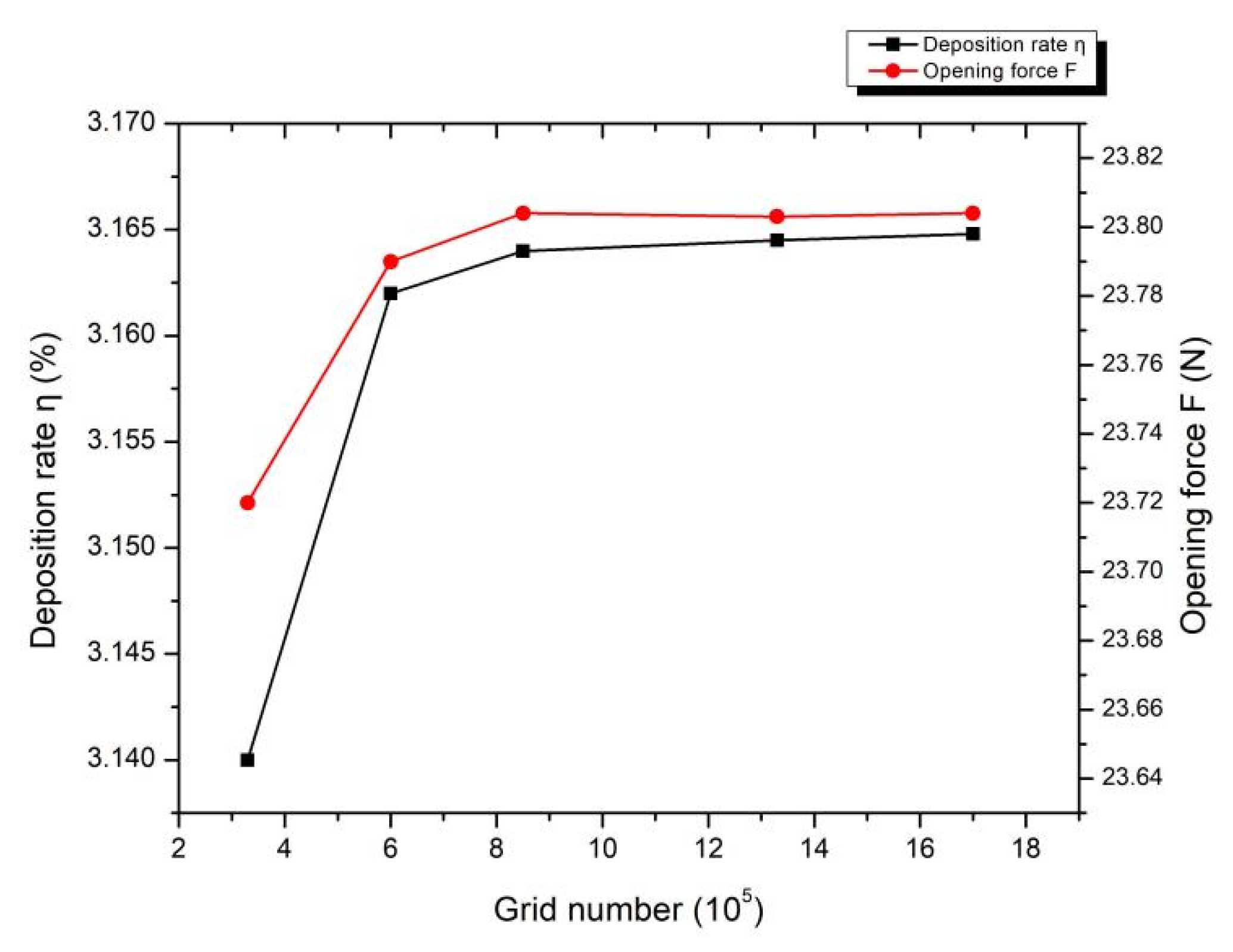
3.1. Boundary Conditions and Grid Division
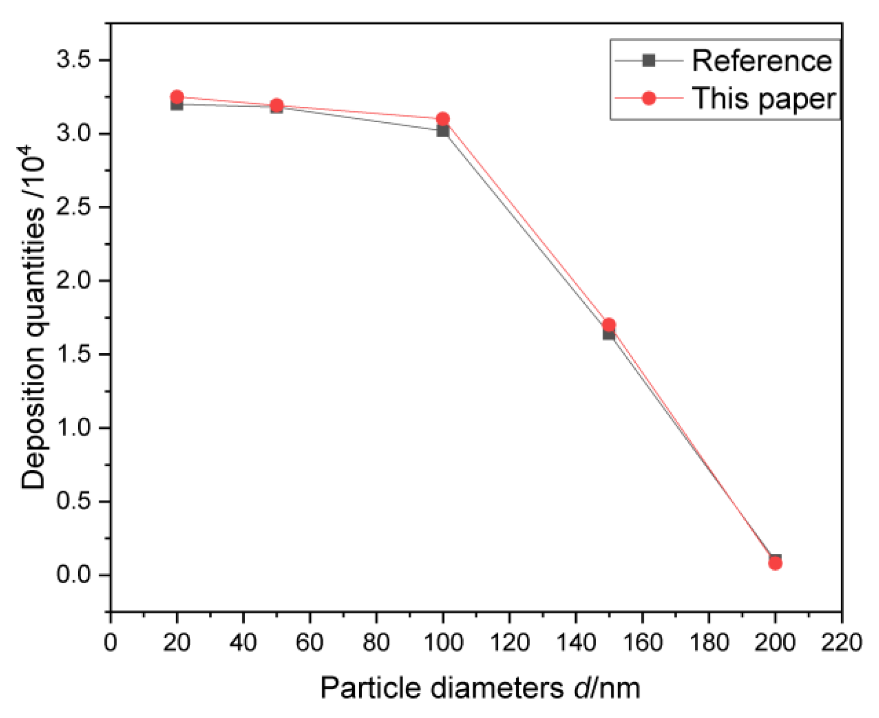
Due to periodic position of spiral grooves, one single period section of the lubrication film is calculated. For when it is at 3000 rpm and the medium pressure is at 0.2 MPa, the deposition ratio and opening force computation results, with various grids, are presented in Figure 3. While grid quantities go beyond 590,000, the computation results are barely variational to the grid number. After overall consideration, we chose a grid number of 590,000. The grid generation is illustrated in Figure 4.
The boundary condition settings are shown in Figure 4. The lubricating film in the spiral groove is set as the rotating water body. The none groove zone is set as the static water body. The rotational ring surface, the axial three side walls of the spiral groove, and the bottom surface of the groove are all arranged as the rotating moving wall surface. The static ring surface is set as the static wall surface. The inlet pressure is set at 0.2 MPa, the outlet pressure is equal to the atmospheric pressure, and the rotational speed ranges from 1000 to 5000 rpm.

3.2. Validation

Before computation, it is important to validate the model by conducting a comparison with other numerical calculations. The spiral groove gas face seal in the literature [26] was calculated to compare the variation rules of deposition quantities and particle diameters. The results presented in Figure 5 in this paper are in good agreement with the literature [26].

4. Results

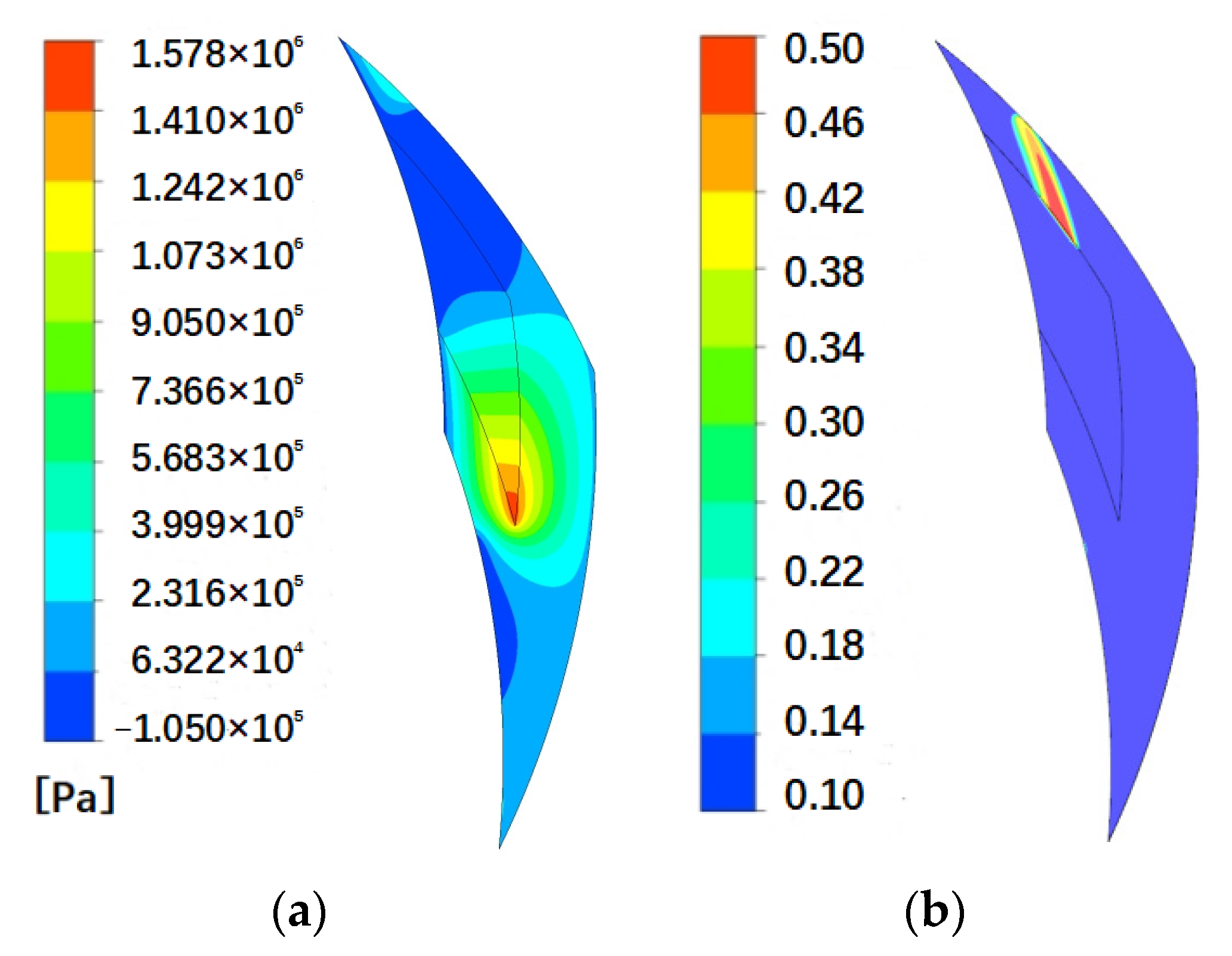
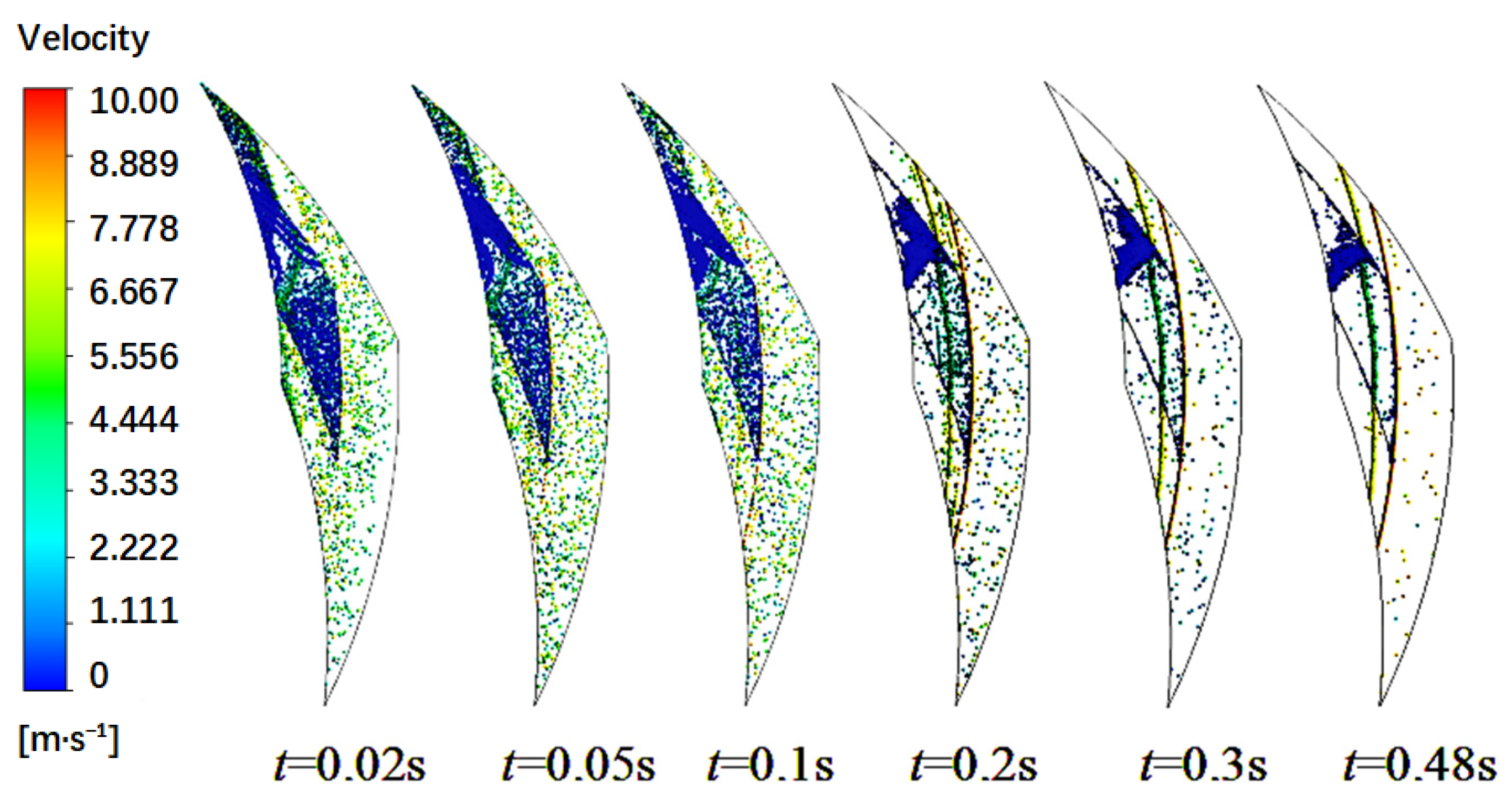
4.1. Continuous Phase Flow Field

To facilitate the analysis of the influence of the groove parameters on the particle deposition, a helical angle of 21°, groove depth of 8 µm, groove width ratio of 0.5, groove diameter ratio of 0.5, particle diameter of 3 µm, rotational speed of 3000 rpm, medium pressure of 0.2 MPa, and particle imports 10% volume fraction of lubrication film simulation calculation, the continuous phase flow field after the stable distribution of film pressure and gas phase volume fraction contours (Figure 6) and the solid particles in lubrication film distribution process of change over time (as shown in Figure 7) are obtained. Moreover, the change process of solid particle distribution in the lubrication film with time is also obtained (as shown in Figure 7). As can be seen from Figure 6a, the pumping effect and dynamic pressure effect of the spiral groove led to the formation of a high-pressure zone at the sharp angle of the outer groove root side whose pressure is higher than the medium pressure. The pressure from the upwind side of the spiral groove to the outer groove root region is high, and a radial isobaric area appears, while the low-pressure zone is formed from the leeward side of the spiral groove to the inner groove root side. Figure 6b shows that the lubrication film cavitation occurs in the middle weir area on the leeward side of the spiral groove and the cavitation area is distributed in a circumferential long strip.
Time starts at the moment when the first particle enters the lubrication film; the particle-releasing period is 0~0.1 s. Figure 7 shows the position and velocity of particles in the lubrication film at different times. A vast number of solid particles are sucked inside the low-pressure zone caused by the spiral groove pumping effects and leeward step diffusion effect. The particles that are sucked from the groove are blocked by the groove side wall and dragged by the pressure gradient on outer groove root, so their velocity stays low. Some particles in the low-pressure zone rest on the outer boundary and leeward side, and others acquire shear power and then proceed to the high-pressure zone inside the grooves or dam region. Those who are sucked from the weir area gain relatively higher velocity, owing to the circumferential flow, then they flow to the dam region under the impact of centrifugal force. Those who reach dam region escape from outer radius side of the lubrication film thrusted by centrifugal force and pressure gradient pointed to outer diameter side of the lubrication film. After particles are completely released (after 0.1 s), the both particles escape of the inner and outer diameter continues, number of particles inside the lubrication film is diminishing, especially those near inner diameter side. Meanwhile, circumferentially distributed particles appear on the cavitation boundary and outer groove root, which proves that radical force is balanced under certain conditions, so the particles perform purely circular motion in certain positions. Particles distribution and deposition quantities are almost stable till it comes to 0.48 s, only few particles stay at outer boundary of low-pressure zone inside the groove, near leeward side, on the outer boundary of cavitation and in the circular zone on the outer groove root. For studying particles deposition characteristics in the lubrication film, we define the ratio of the number of residual particles in the lubrication film to the number of particles sucked from the inner diameter side as solid particles deposition ratio.

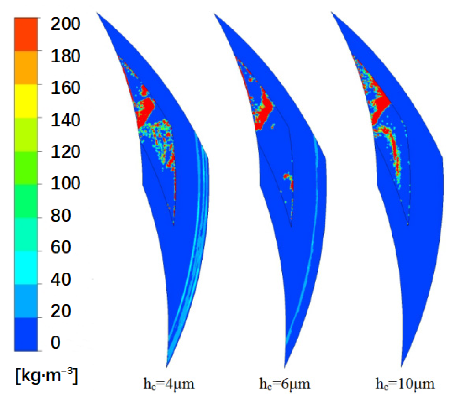
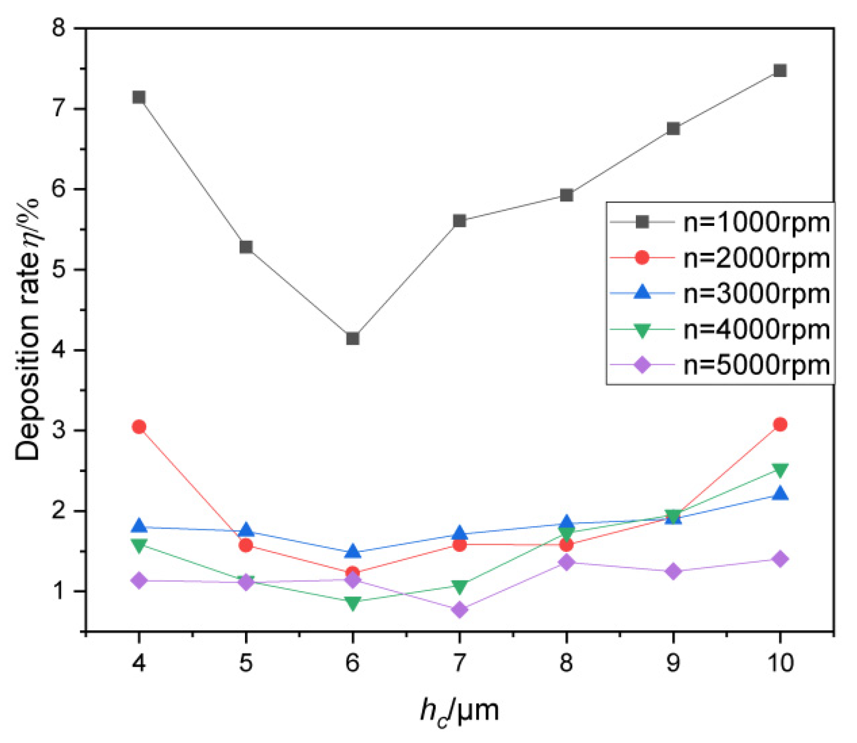
4.2. The Influence of Groove Depth on Particle Deposition Distribution and Deposition Rate

The simulation computation was carried out under the conditions of the following parameters: spiral angle of 21°, groove diameter ratio of 0.5, and groove width ratio of 0.5. Figure 8 shows the deposition distribution of solid particles at different groove depths at 1000 rpm, and Figure 9 shows the deposition rate variation with groove depths at different rotational speeds.
As can be seen in Figure 8, the particle deposition inside the grooves is distinct and it extends from the low-pressure zone to outer groove root. Especially when the groove depth is lower, the hydrodynamic effect is relatively weaker. Thus, the film pressure on the outer groove root side is relatively low, and the circumferential particle deposition belt generates because of the reducing pressure gradient in the dam region. With the groove depth increasing, the circumferential deposition belt shrinks and ultimately vanishes, thus making the groove zone become the main deposition region.
It can be seen from Figure 9 that the particle deposition rate first decreases and then increases with the increase of the groove depth. The optimal depth of the groove is about 6 µm. On the whole, the deposition rate decreases when the rotational speed increases. When the rotational speed is lower than 2000 rpm, the influence of the groove depth on the deposition rate is obvious, and the influence is weak when the rotational speed is higher than 3000 rpm. This shows that, with the increase of the rotational speed, the high-speed cause pumping effect and dynamic pressure effect play a leading role, and the influence of the groove depth is relatively reduced. At the same time, since the film pressure significantly increases, both the centrifugal force and the pressure gradient increase, and the escape of particles from the side of the lubricating film diameter significantly increases, leading to an obvious sedimentation rate decrease.

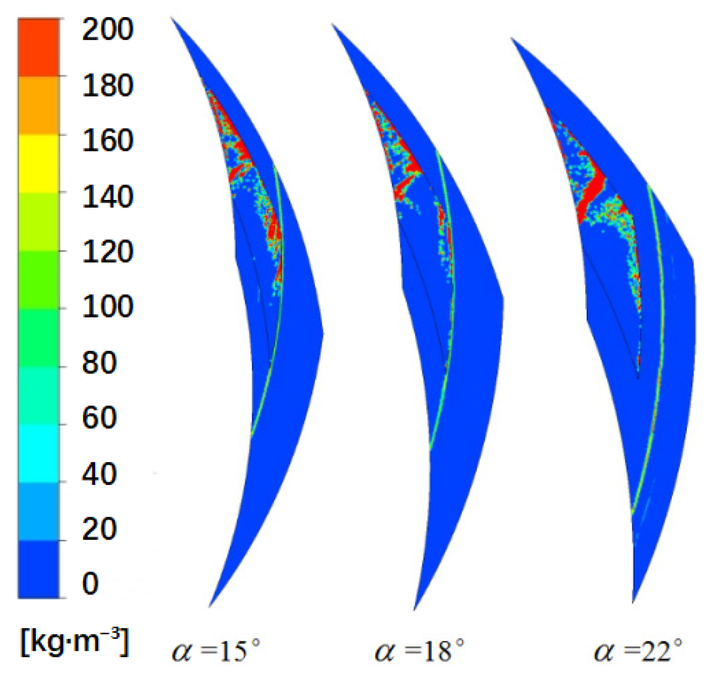
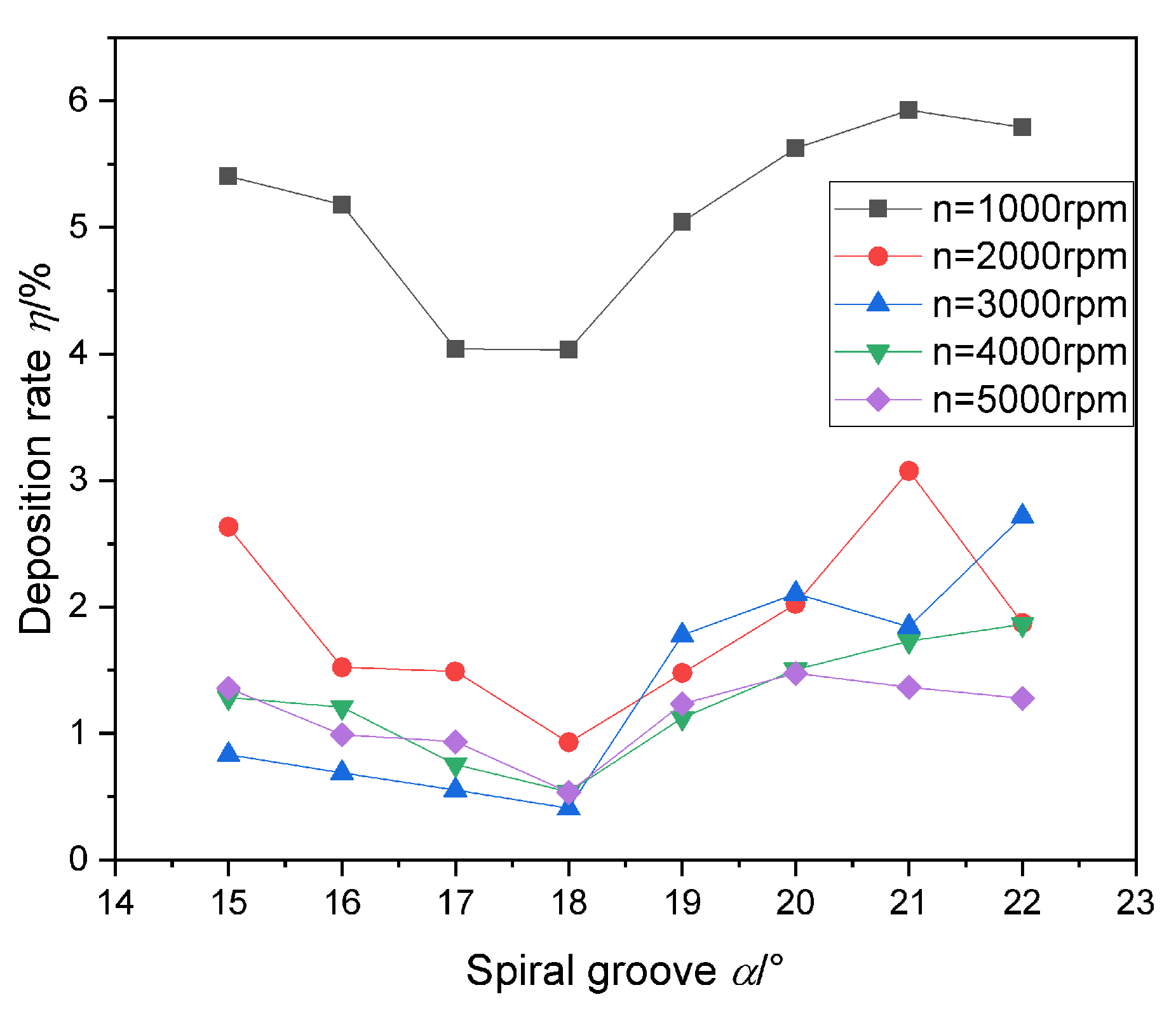
4.3. The Influence of Spiral Angle on Particle Deposition Distribution and Deposition Rate

When both the groove diameter ratio and the groove width ratio are 0.5, in order to make the study universal, we choose an 8 μm groove depth to conduct computation. Figure 10 presents solid particles’ distribution with different spiral angles and 1000 rpm. Figure 11 shows deposition rate variation rules with the different spiral angle and different rotational speed.
We can perceive from Figure 10 that the particle deposition zone has almost thoroughly covered half of the leeward groove zone that starts from the inner groove root side to the outer groove root side. There is also a circumferential deposition belt on the outer groove root circle. When the spiral angle comes to 18°, apart from the low-pressure zone, the particle deposition zone inside the groove apparently shrinks. However, when it comes to 22°, the particle deposition zone inside the groove contrarily expands. Though the circumferential deposition belt on the outer groove root circle vanquishes, the belt reappears in the dam region. This specifies that a spiral groove that is too small brings about a much too slim and long groove zone, which enhances the capability of the groove to prevent particles from expelling. However, its hydrodynamic capacity is much stronger and the film pressure is higher, so the dam region is difficult to be deposited. However much too large spiral angle makes the groove zone too fat and too short, which enlarges low-pressure zone and weakens the work of shear force. The hydrodynamic effect is relatively weaker in this case, adding that low film pressure, particles find it hard to flee from the groove. Moreover, the deposition easily occurs, of course. Therefore, a proper spiral angle will be convenient for both particle expelling and deposition avoiding.
We can see from Figure 11 that the deposition rate first decreases and then increases with the increase of the spiral angle, and the most appropriate spiral angle is about 18°. It can also be seen that the effect of the too-large spiral angle on the deposition rate is greater than that of the too-small spiral angle, thus verifying that the spiral angle with strong pumping effect is more important to reduce the deposition rate, because the particles can obtain more energy from the stronger shear work, move to the weir region, and escape to the outside diameter side under the action of greater pressure gradient force in the dam region.

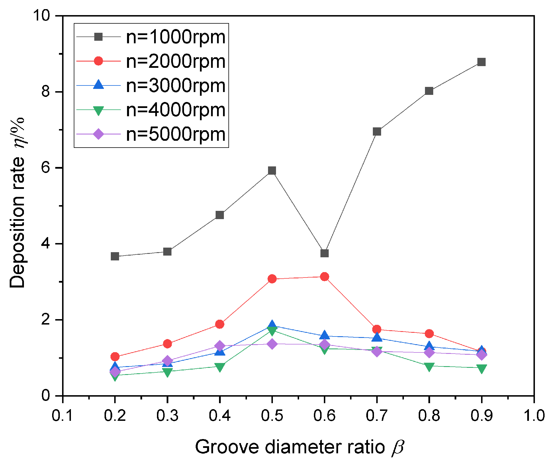
4.4. The Effects of Groove Diameter Ratio on Particle Deposition Distribution and Deposition Rate

The simulation computation was carried out under the conditions of parameters such as the groove depth of 8 µm, the spiral angle of 21°, and the groove width ratio of 0.5. Figure 12 illustrates the distribution of particles deposition with different groove diameters (rotational speed: 1000 rpm). The variation rule of the deposition rate with the groove diameter ratio at different rotational speeds is visible in Figure 12.
It is visible in Figure 12 that a too-high or too-low groove diameter ratio results in a serious deposition. When the groove diameter ratio is 0.5, the deposition in groove is not intense enough, even though the circumferential belt still exists in the dam region near the outer diameter side. It turns out that wide and flat spiral grooves brought by a low groove diameter ratio weakens the hydrodynamic effect and pumping effect; moreover, the differential pressure flow is stronger than the pumping flow, and the deposition becomes hard outside the groove. Nevertheless, particles that enter the groove, due to the action of pressure gradient, are apt to deposit in the major groove region, except for little areas near the upwind side. Although a too-high groove diameter ratio heightens the hydrodynamic effect and pumping effect, the ability to maintain high pressure at the outer groove root is reduced by a narrow dam region. Particles inside the groove are influenced less effectively by a pressure gradient pointed to the inner diameter side, so deposition in grooves aggrandize eventually. Thus, a suitable groove diameter ratio helps sustain a certain hydrodynamic and pumping effect, and a high-pressure zone is more easily formed in the dam region than on outer groove root side. The deposition will alleviate because of the increase of the pressure gradient. However, there is circular deposition around the dam region, with a comprehensive influence of both the width of the dam region and the high-pressure zone. In that, choosing a reasonable groove diameter ratio to erase the deposition is possible.
As can be seen from Figure 13, the influence rule of the groove diameter ratio on deposition rate is obviously different from other rotational speeds when the rotational speed is 1000 rpm. Generally, the deposition rate increases significantly with the increase of groove diameter ratio, but it drops to the lowest point when the groove diameter ratio is 0.6. This is because, at a low rotational speed, the particles are subjected to a small centrifugal force, the hydrodynamic effect and the pumping effect are weak, few particles escape from the outer diameter side, and the deposition in the groove is prominent. With the increase of the groove diameter ratio, the groove increases the space for particle deposition, and the deposition rate increases. However, the special case is when the groove diameter ratio is 0.6. It may be caused by the fact that the circumferential sedimentary belt in the dam region under this groove diameter ratio begins to disappear and the sediment in the channel area is still in a relatively light state. When the rotational speed increased to more than 2000 rpm, the deposition rate was significantly lower than that at a lower rotational speed, and the change rule was that the deposition rate first increased and then decreased with the increase of the groove diameter ratio. The deposition rate was the largest when the groove diameter ratio was about 0.5. The deposition rate was the largest when the groove diameter ratio was about 0.5. For example, when the rotating speed is 2000 rpm, the deposition rate of groove diameter ratio 0.5 is about 200% higher than that of groove diameter ratio of 0.2.
In order to measure the sensitivity of the deposition rate to the change of the groove diameter ratio, the ration of the sensitivity of the deposition rate to the groove diameter is defined as the ratio of the change of deposition rate to the change of corresponding groove diameter ratio. This is denoted by G. The variation curve of ratio of the sensitivity of the deposition rate to the groove diameter, along with the rotating speed, is shown in Figure 14. With the increase of the rotating speed, the ratio of the sensitivity of the deposition rate to the groove diameter decreases continuously. When the rotating speed increases from 1000 to 2000 rpm, the sensitivity decreases sharply, while when the rotating speed increases from 2000 to 5000 rpm, the sensitivity decreases slowly. It shows that the lower the speed is, the more sensitive the deposition rate is to the groove diameter ratio. The sensitivity at 1000 rpm is 14 times that at 5000 rpm. The higher the speed, the less sensitive the deposition rate is to the groove diameter ratio. This shows that the increase of rotational speed, the increase of particles in centrifugal force, the hydrodynamic effect of the spiral groove, and the pumping effect are obviously enhanced, and the lubrication film, particle movement, and film pressure played a leading role in aspects such as making particles that entered the groove escape from the inner diameter side, thus effectively reducing the deposition rate. In contrast, the medium groove diameter ratio does not have the obvious advantages of the above aspects, resulting in a relatively high deposition rate.

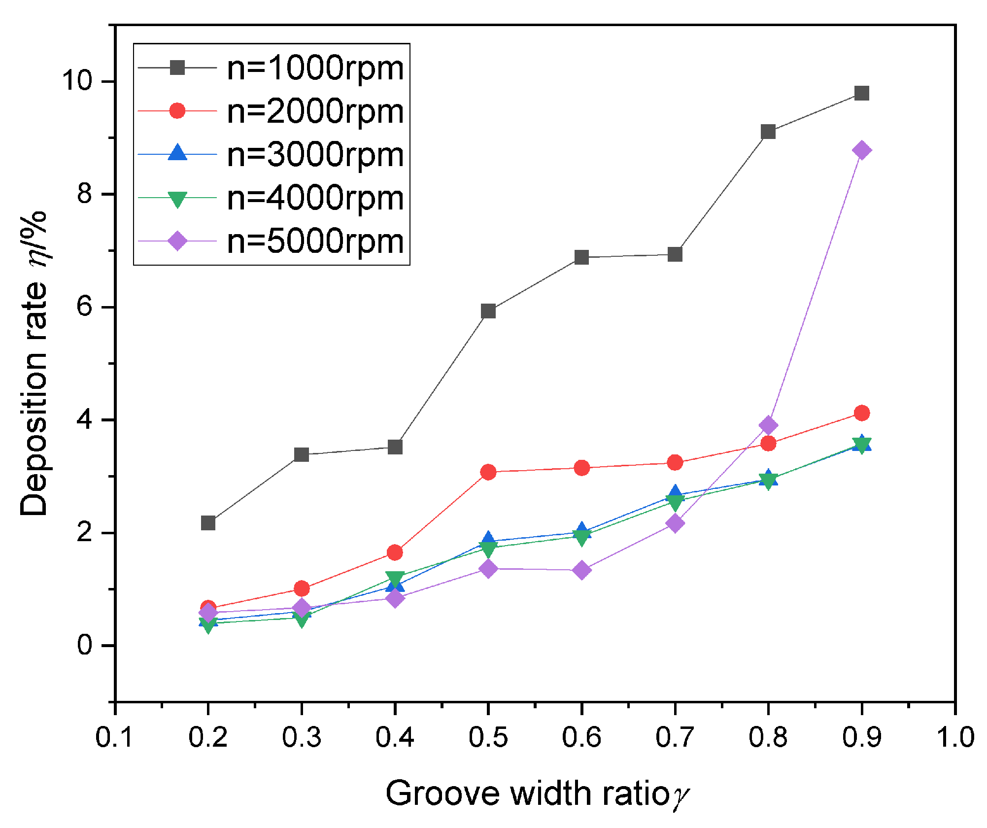
4.5. The Effects of Groove Width Ratio on Particle Deposition Rate and Sealing Performance

The simulation computation was carried out with the following parameters: groove depth of 8 µm, spiral angle of 21°, and groove diameter ratio of 0.5. Figure 15 presents the solid particles’ distribution with different groove width ratios and 1000 rpm rotational speed. Figure 16 shows deposition rate variation rules, along with the different rotational speed.
As can be seen in Figure 15, when the groove width ratio is 0.2, some particles stay in the low-pressure zone inside the groove, and others make up two circumferential deposition belts at the outer groove root and in the dam region. As the groove width ratio comes to 0.6, the circumferential deposition belt moves toward the outer diameter. When it comes to 0.9, the deposition arises near the upwind side and tends to expand to the inner diameter side, and the circumferential deposition belt vanquishes. This is because the groove zone is long and narrow when the groove width ratio is low, the pumping effect is relatively weak, the film pressure is low, and the pressure gradient in the dam region is small, leading to the formation circumferential deposition belt. A moderate increase of the groove width ratio can strengthen the pumping effect, the film pressure in the high-pressure zone goes up, and the pressure gradient increases, resulting in the circumferential deposition belt moving toward the outer diameter side. However, a groove width ratio that is too high makes the groove wider and flow inside the groove more sophisticated. Backflow appears on the leeward side of groove, and the outer groove root is too close to the adjacent low-pressure zone of spiral groove. The above factors all contribute to the decrease of high pressure and particles deposition inside the groove, as shown in Figure 15.
As seen in Figure 16, the deposition rate increases with the increase of the groove width ratio, and the higher the rotational speed is, the lower the deposition rate increases. At 1000 rpm, the deposition rate of groove width ratio, 0.9, is about 400% higher than that of groove diameter ratio, 0.2. However, when the rotational speed reaches 5000 rpm and the groove width is relatively high, the deposition rate increases sharply. This indicates that the increase of the groove width ratio and the increase of groove is the space of the main deposition area, which is the main factor for the increase of deposition rate. The higher the rotational speed, the stronger the hydrodynamic effect and pumping effect, and the greater the probability of particle escaping from the outer diameter side, leading to the increase of the rotational speed and the slowdown of the deposition rate. When the rotational speed reaches 5000 rpm, the flow in the groove becomes more complicated, the re-flux becomes more obvious, and the deposition in the low-pressure zone is intensified. The high pressure in the outer groove root is significantly affected by the low-pressure zone in the adjacent spiral groove, and the deposition near the outer groove root may also be aggravated, resulting in a sudden increase in the deposition rate of high rotation speed and high groove width ratio.

5. Conclusions

The deposition rate decreases first with the increase of groove depth and spiral angle. Moreover, when the groove depth is above 6 µm and the spiral angle is above 18°, the deposition rate increases.
The deposition rate increases as the groove diameter ratio increases when it is at 1000 rpm. However, when the groove diameter ratio is 0.6, the deposition rate drops. When the rotating speed is 2000 rpm, the deposition rate of groove diameter ratio 0.5 is about 200% higher than that of groove diameter ratio 0.2. When the rotational speed goes above 2000 rpm, the deposition rate increases first and then decreases with the increase of the groove diameter ratio. The deposition rate reaches its highest value when the groove diameter ratio is 0.5. The lower the speed is, the more sensitive the deposition rate is to the groove diameter ratio. The sensitivity at 1000 rpm is 14 times that at 5000 rpm.
The deposition rate increases with the increase of groove width ratio. At 1000 rpm, the deposition rate of groove width ratio, 0.9, is about 400% higher than that of groove diameter ratio, 0.2. When it comes to 5000 rpm, an overlarge groove width ratio makes the deposition expend toward the inner diameter side; thus, the deposition rate soars under a high groove width ratio.

Author Contributions

Conceptualization, H.C. and B.Z.; Data curation, Z.W., J.L. and K.G.; Formal analysis, Y.C. and Q.C.; Funding acquisition, H.C.; Investigation, Y.C. and Q.C.; Methodology, B.Z.; Software, Z.W., J.L. and K.G.; Writing—original draft, Z.W., J.L. and K.G.; Writing—review & editing, H.C., Y.F. and B.Z. All authors have read and agreed to the published version of the manuscript.

Funding

This research was funded by [the National Natural Science Foundation of China] grant number [No. 51976078].

Institutional Review Board Statement

Not applicable.

Informed Consent Statement

Not applicable.

Data Availability Statement

Not applicable.

Acknowledgments

The authors gratefully acknowledged that the work is supported by the National Natural Science Foundation of China (No. 51976078).

Conflicts of Interest

The authors declare no conflict of interest.

References

  1. Brunetière, N.; Rouillon, M. Fluid flow regime transition in water lubricated spiral grooved face seals. Tribol. Int. 2021, 153, 106605. [Google Scholar] [CrossRef]
  2. Findlay, J.A. Cavitation in mechanical face seals. J. Lubr. Technol. 1968, 90, 356–364. [Google Scholar] [CrossRef]
  3. Gao, W.; Huang, W.; Wang, T.; Liu, Y.; Wang, Z.; Wang, Y. Numerical model of two-phase mechanical face seal with shallow grooves based on finite volume method. Ind. Lubr. Tribol. 2020, 72, 1303–1309. [Google Scholar] [CrossRef]
  4. Li, Z.; Hao, M.; Yang, W.; Zhuang, Y.; Wang, X.; Sun, X. Study of the effects of cavitation on steady characteristics of liquid film seals based on CFD technique. Lubr. Seal. 2016, 41, 26–31. [Google Scholar]
  5. Li, Z.; Hao, M.; Yang, W.; Han, J.; Ren, B. Effects of waviness and taper on cavitation characteristics of liquid lubricated mechanical seals. J. Chem. Ind. Eng. 2016, 67, 2005–2014. [Google Scholar]
  6. Li, Z.; Hao, M.; Cao, H.; Yang, W.; Wang, Y.; Sun, X. Analysis of cavitation and load-carrying capacity of liquid film seals with consideration of surface roughness. Lubr. Seal. 2017, 42, 1–6. [Google Scholar]
  7. Chen, H.; Sun, D.; Wu, Y.; Chen, M.; Zhang, P. Effect of solid particles on Cavitation and Lubrication Characteristics of Upstream Pumping Mechanical Seal Liquid Membrane. Int. J. Fluid Mach. Syst. 2017, 10, 412–420. [Google Scholar] [CrossRef]
  8. Payvar, P.; Salant, R.F. A Computational Method for Cavitation in a Wavy Mechanical Seal. J. Tribol. 1992, 114, 199–204. [Google Scholar] [CrossRef]
  9. Qiu, Y.; Khonsari, M.M. On the Prediction of Cavitation in Dimples Using a Mass—Conservative Algorithm. J. Tribol. (EMO-04) 2009, 131, 41702–41711. [Google Scholar] [CrossRef]
  10. Ji, H.; Wang, Y.; Zhan, L.Y.; Jiang, S.; Chen, Z. Effect of multi wedge phenomenon on performance of equilateral triangular microporous end face mechanical seal. Adv. Eng. Sci. 2019, 51, 168–175. [Google Scholar]
  11. Xu, X.; Ma, C.; Zhang, Y.; Sun, J.; Yu, Q. Influence of Groove Structure Parameters Based on Optimal Mass Transfer Coefficient on Vaporization Characteristics and Sealing Performance of Liquid Film Mechanical Seals. Appl. Sci. 2021, 11, 8941. [Google Scholar] [CrossRef]
  12. Zhao, D.Y. Numerical Simulation of Gas-Solid Two-Phase Flow in Self-Lubricating Sliding Bearing. Master’s Thesis, University of Science and Technology Liaoning, Anshan, China, 2018; p. 1. [Google Scholar]
  13. Su, W.T.; Li, Y.; Wang, Y.H.; Zhang, Y.N.; Li, X.B.; Ma, Y. Influence of structural parameters on wavy-tilt-dam hydrodynamic mechanical seal performance in reactor coolant pump. Renew. Energy 2020, 166, 210–221. [Google Scholar] [CrossRef]
  14. Peng, X.D.; Yu, M.B.; Meng, X.K.; Bai, S.; Sheng, S. Effect of face wear on sealing performance of U-grooved mechanical seals. J. Shanghai Jiaotong Univ. (Nat. Ed.) 2010, 44, 1721–1726. [Google Scholar]
  15. Yan, Y.; Chen, W.; Sun, J. Numerical simulation of performance for bidirectional self-pumping hydrodynamic static mechanical seal. J. Drain. Irrig. Mach. Eng. 2017, 35, 692–699. [Google Scholar]
  16. Chen, Q.; Sun, J.J. Analysis of self-cleaning for self-pumping hydrodynamic and hydrostatic mechanical seal. Tribology 2019, 39, 259–268. [Google Scholar]
  17. Chen, H.; Zuo, M.; Wu, Q.; Xu, C.; Wang, Y.; Li, S. Solid-liquid two-phase flow characteristics of lubricating film in upstream pumping mechanical seal. J. Drain. Irrig. Mach. Eng. 2015, 33, 685–690. [Google Scholar]
  18. Chen, H.; Wang, Q.; Li, W.; Zhang, J. Numerical simulation of three-dimensional micro-clearance flow field of upstream pumped mechanical seal with spiral groove based on Fluent. Lubr. Seal. 2012, 37, 16–19. [Google Scholar]
  19. Khonsari, M.M.; Wang, S.H.; Qi, Y.L. A Theory of liquid-solid lubfication in elasto hydrodynamic regime. J. Tribol. 1989, 111, 440–444. [Google Scholar] [CrossRef]
  20. Hao, M.M.; Cai, H.Z.; Liu, W.B.; Li, Z. Numerical analysis on gas-liquid two-phase flow of outward pumping spiral-grooved mechanical seal clearance. J. China Univ. Pet. (Nat. Sci. Ed.) 2015, 39, 129–137. [Google Scholar]
  21. Li, Y. The Research on Numerical Simulation and Abrasion Property of Solid-Liquid Two-Phase-Flow Centrifugal Pump; Zhejiang University of Science and Technology: Hangzhou, China, 2014. [Google Scholar]
  22. Zhao, B.J.; Yuan, S.Q.; Liu, H.L.; Huang, Z.F.; Tan, M.G. Simulation of solid-liquid two-phase turbulent flow in double-channel pump based on mixture model. Trans. CSAE 2008, 24, 7–12. [Google Scholar]
  23. Wu, Y.; Tang, X.; Liu, S.; Xu, N. Hydraulic Mechanical Cavitation and Solid-Liquid Two-Phase Fluid Dynamics; China Hydropower Publishing House: Beijing, China, 2007; pp. 31–37. [Google Scholar]
  24. Wang, F.J. Computational Fluid Dynamics Analysis; Tsinghua University Press: Beijing, China, 2004; pp. 4–7. [Google Scholar]
  25. Wu, Q.B. Study on Cavitation Characteristics of Dynamic Pressure Mechanical Seal with Liquid Film Lubrication; Jiangsu University: Zhenjiang, China, 2015. [Google Scholar]
  26. Feng, M.; Hou, C.; Hu, M.X.; Liu, Z.H. Motion and deposition of submicron particles in aerodynamic thrust bearing. J. Chin. Inert. Technol. 2019, 27, 227–234. [Google Scholar]
Figure 1. Spiral groove shape of the end face of the mechanical seal rotational ring.
Energies 15 03893 g001
Figure 2. Three-dimensional model of lubricating film.
Energies 15 03893 g002
Figure 3. Grid independence validation.
Energies 15 03893 g003
Figure 4. Diagram of 1/N lubrication film mesh and boundary conditions.
Energies 15 03893 g004
Figure 5. Comparison of simulation results of solid particle deposition.
Energies 15 03893 g005
Figure 6. Calculation results of continuous phase flow field. (a) Film pressure distribution; (b) Volume fraction distribution of gas phase.
Energies 15 03893 g006
Figure 7. Distribution and movement of particles with time.
Energies 15 03893 g007
Figure 8. Particles distribution with different groove depths.
Energies 15 03893 g008
Figure 9. Influence of groove depth on the deposition rate.
Energies 15 03893 g009
Figure 10. Particles’ distribution with different spiral angle.
Energies 15 03893 g010
Figure 11. Influence of spiral angle on the deposition rate.
Energies 15 03893 g011
Figure 12. Particles’ distribution with different groove diameter ratios.
Energies 15 03893 g012
Figure 13. Influence of groove diameter ratio on the deposition rate.
Energies 15 03893 g013
Figure 14. Sensitivity at different speeds.
Energies 15 03893 g014
Figure 15. Particles’ distribution with different groove width ratios.
Energies 15 03893 g015
Figure 16. Influence of groove width ratio on the deposition rate.
Energies 15 03893 g016
Table 1. Geometric parameters and numerical values of the seal face.
Geometrical ParametersValue
Inner radius of seal ring, ri/mm26
Outer radius of seal ring, ro/mm31
Spiral groove outer root radius, rg/mm27~30.5
Spiral angle, α15~22
Groove number, N12
Depth of groove, hc/μm4~10
Groove diameter ratio, β0.2~0.9
Groove width ratio, γ0.2~0.9
Publisher’s Note: MDPI stays neutral with regard to jurisdictional claims in published maps and institutional affiliations.

