Article

A Proposed Controllable Crowbar for a Brushless Doubly-Fed Reluctance Generator, a Grid-Integrated Wind Turbine

1
Electrical Engineering Department, Faculty of Engineering, South Valley University, Qena 83521, Egypt
2
Electrical Engineering Department, Qena Faculty of Engineering, Al-Azhar University, Qena 83513, Egypt
3
Energy Technology Program, School of Engineering, Purdue University, West Lafayette, IN 47906, USA
*
Author to whom correspondence should be addressed.
Energies 2022, 15(11), 3894; https://doi.org/10.3390/en15113894
Submission received: 1 April 2022 / Revised: 10 May 2022 / Accepted: 23 May 2022 / Published: 25 May 2022
(This article belongs to the Special Issue Wireless Power Transfer for Electric Vehicles)

Abstract

:
Brushless doubly fed reluctance generators (BDFRGs) are hopeful generators for using inside variable speed wind turbines (VSWTs), as these generators introduce a promising economical value because of their lower manufacturing and maintenance costs besides their higher reliability. For integrating WT generators, global networks codes require enabling these generators to stay connected under grid disturbances. The behavior of the BDFRG is strongly affected by grid disturbances, due to the small rating of the used partial power converters, as these converters cannot withstand high faults currents which leads to quick tripping of BDFRG. VSWTs can be safeguarded against faults using the crowbar. Usually, the conventual crowbar is shunt connected across the converter to protect it, but this configuration leads to absorbing reactive power with huge amounts from the grid, leading for more voltage decaying and more power system stability deterioration. This study proposes a simpler self-controllable crowbar to enhance the ability of the BDFRG to remain in service under faults. The operation technique of the proposed crowbar is compared to other crowbar operation techniques, the effectiveness of the proposed system would be analyzed. Through the simulation results and behavior analysis, the proposed crowbar technique demonstrates a decent improvement in the conduct of the studied system under faults.

1. Introduction

Because of the ongoing rise in the prices of fossil resources, which mostly have an exhausted impact on the world’s economies, as well as the harmful influence of these resources on the environmental footprint, the world rapidly resorts to utilizing sustainable resources. Indeed, the wind energy conversion system (WECS) has emerged as one of the fastest-growing energy systems [1,2,3,4]. Doubly fed induction generator (DFIGs) introduced a main important advantage since these generators are based on using a partial converter which means lower cost than the generators that use a complete power converter, leading to a great spread of DFIGs in wind energy markets. Brushless doubly fed machines (BDFMs) are slip recovery machines that reduce the required power converter if the required speed control range is limited, resulting in a significant cost saving for these machines [5]. As a result, using this BDFM is a cost-effective option for using inside the variable-speed WECS. Another main advantage of the BDFMs over the traditional DFIGs is their reliability, as the brush gear and slip rings were removed. Nowadays, both the brushless doubly fed reluctance machine (BDFRM) and brushless doubly fed induction machine (BDFIM) attract the most attention from researchers, especially on the subjects of stability, maximizing the extracted power and power quality. The main significances of the BDFRM’s rotor design are to give it; higher reliability, robustness, and operation free from maintenance. Moreover, considering the lack of rotor copper losses, the BDFRM is expected to outperform the BDFIM in terms of efficiency [6,7,8]. As a result, the brushless doubly fed reluctance generator (BDFRG) is discovered to be the most appealing for WECS [9,10,11]. Moreover, the BDFRG has been studied in a lot of fields by researchers as mentioned in papers [12,13,14,15].
Some of the grid codes considered that WTs have to be able to remain connected under zero voltage for a duration time up to 150 ms [16,17,18,19,20]. As the stator windings of the BDFRG are tied directly to the network, any occurrence of grid disturbances especially voltage dip can easily lead to an abrupt absence of the BDFRG magnetization, raising the current values in the machine side converter (MSC) above the threshold value and also raising the voltage of the DC-link above the threshold value, which can easily lead to destroying the power converter [21]. So, there are many different technical challenges facing the ability of the BDFRGs to satisfy the grid codes’ requirements of keeping these generators connected under faults, principally due to the lower ratings of the used partial power converters.
This study is the first one to boost the ability of the BDFRG of staying connected during faults by using the crowbar. Commonly, currently, there are two used solutions to promote the ability of the doubly fed generators to keep connected during faults: using the crowbar and applying the demagnetization method [20]. Usually, when the crowbar was applied to protect the doubly fed generators during the occurrence of faults, the Machine Side Converter (MSC) is short-circuited, absorbing from the grid large amounts of reactive power, meaning more voltage dropping and more instability for the grid [22]. While on the other side, applying the demagnetization method [23,24], based on controlling the output of the MSC for tracing and counteracting the stator flux oscillations to eliminate the occurred transients on the induced electromagnetic force in the rotor winding. However, the industrial realization of the demagnetization method is very complex [20].
This paper introduces a proposed solution for increasing the ability of the grid-connected BDFRG WT to remain in service under the occurrence of faults and subsequently increasing the ability of the BDFRG to satisfy the grid code requirements. The proposed solution is mainly depending on using a new automatically controllable crowbar protection technique. One of the main aims of the proposed solution is keeping the connecting of the BDFRG MSC during the faults, reducing reactive power absorption from the network. For assessing the proposed solution efficacy, the “BDFRG grid-connected wind farm” performance would be examined under the occurrence of heavy conditions of different faults with and without using the proposed solution.

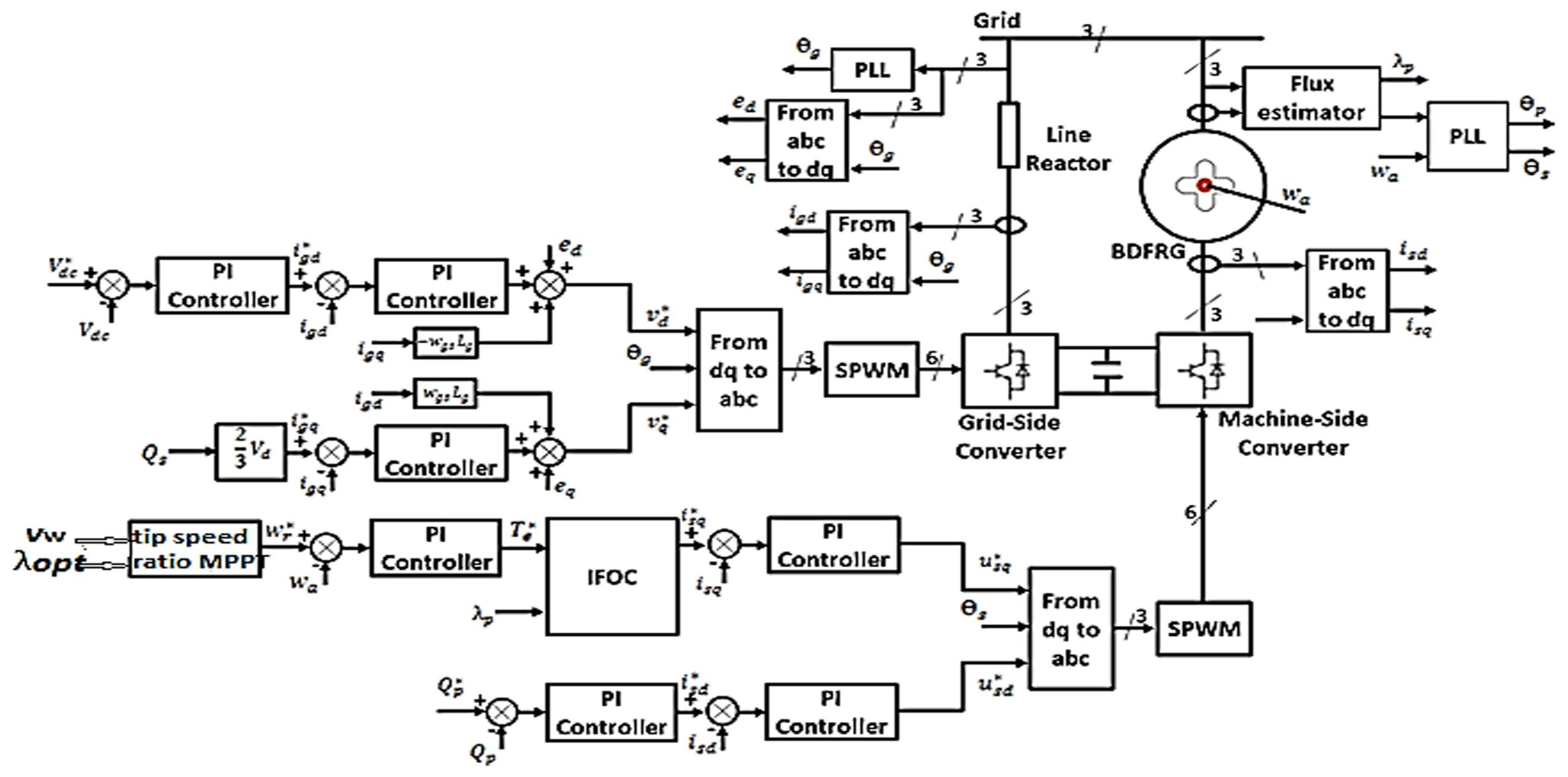
2. BDFRG Dynamic Model
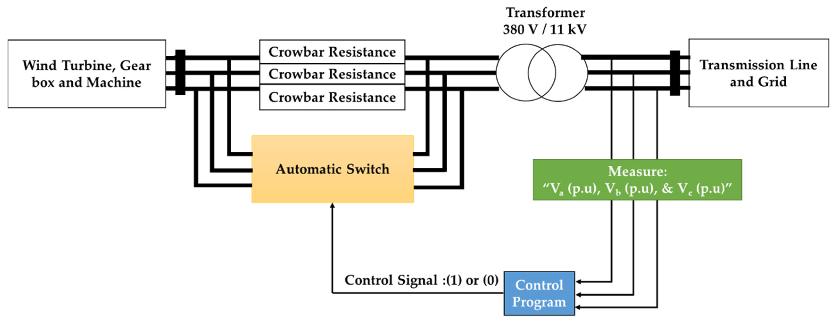
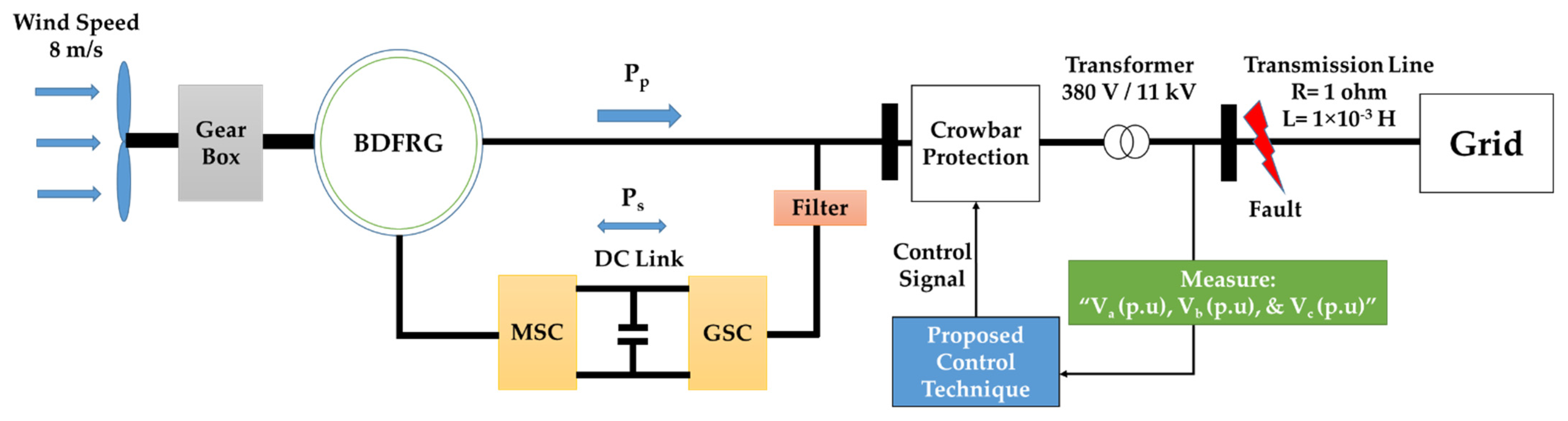
The BDFRG dynamic model is based on the theory of space vector, shown in Equations (1)–(3) [4]. The process of decoupling both the torque-producing and flux-producing current components is only possible in a special kind of frame transformation. This is mainly because of the bizarre structure of the BDFRG and the fact that the primary and secondary windings electrical quantities (current, flux, etc.) both have variant pole numbers and also different frequencies. The primary winding quantities are transformed into a general reference frame that rotates at a speed of ω while the secondary winding quantities are transformed into another frame that rotates at speed of ( ω r ω ) [25]. The general frame speed is preferred to be the same as the primary winding supply frequency. The resulting dynamic model based on the dual frame transformation is described by Equation (1). The flux equation is presented in Equation (2). Finally, the electromagnetic torque and mechanical speed expressions can be stated as in Equation (3) [26,27].
v d p = r p     i d p + d d t   λ d p ω   λ q p
v q p = r p   i q p + d d t λ q p + ω   λ d p
v d c = r c   i d c + d d t   λ d c ( ω r ω )   λ q c
v q c = r c     i q c + d d t   λ q c + ( ω r ω )   λ d c
λ d p = L p   i d p + L p c   i d c
λ q p = L p   i q p L p c   i q c
λ d c = L c   i d c + L p c   i d p
λ q c = L c   i q c L p c   i q p
T e = 3 2   p r   [ λ d p   i q p λ q p   i d p ]
(   J r + n g 2     J g )   d   ω r m   d t = n g   T m + n g 2     T e  
As described in Figure 1, the system consists of the BDFRG driven by WT The BDFRG is tied to the network by the power and control windings. The power winding is directly connected, while the control winding is connected via two converters: Machine Side Converter (MSC) and Grid Side Converter (GSC). A capacitance is placed between two converters. Each converter has its own controller in order to assure that it functions properly. Both the MSC and GSC controllers are shown in Figure 1. The MSC controller has two branches; one of them is connected to MPPT, this branch calculates the reference quadrature secondary voltage by using indirect field-oriented control. The other branch calculates the reference direct secondary voltage. These two reference voltages are transformed from dq frame to abc frame by using ( θ s ) to obtain appropriate gate signals from Sinusoidal Pulse Width Modulation (SPWM). On the other hand, the GSC controller has also two branches as illustrated in Figure 1. The two branches calculate reference quadrature and direct grid voltages. Then, they are transformed from dq frame to abc frame by using ( θ g ) to get appropriate gate signals from SPWM to adjust the DC link voltage and secondary reactive power on its reference values.

3. The Crowbar

The crowbar is one of the used solutions in the cases of severe disturbances such as heavy faults. In general, the crowbar provides a safe path for the heavy fault currents by short-circuiting the original path, subsequently damping the destroying fault currents and protecting the generator from the increased (overrated) currents. Basically, crowbar consists of a three-phase resistance called crowbar resistance. These resistances could be connected and disconnected by means of power electronics switches. Severe disturbances lead to raising the currents in the generator above the allowable values, and also disturb the DC link voltage. In general, the activation (connection) process of the crowbar protection system is carried out only in the case of severe disturbances (heavy faults). After clearing the disturbance (fault), if the current and the DC link voltage are returned back to its allowable values, the crowbar will be deactivated (disconnected). Moreover, the generator returned back to its normal configuration. If the current and the DC link voltage are not returned to its allowable values, the activation of the crowbar protection system can be restarted. Moreover, the crowbar has been studied in a lot of fields by researchers as mentioned in the paper [28,29,30].

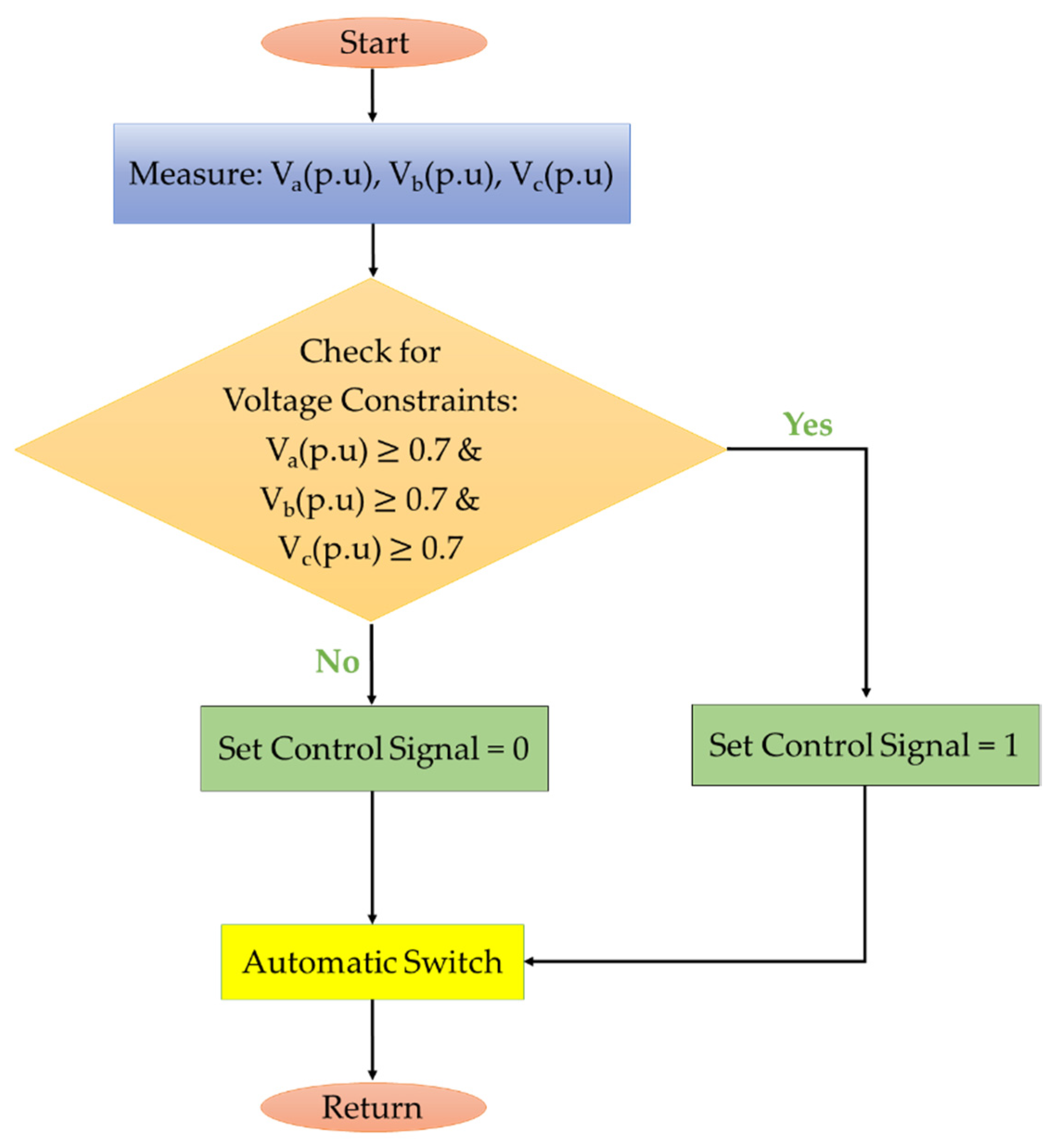
4. The Proposed Crowbar Control Strategy

The crowbar activation and deactivation processes are important issues, there are many used techniques for crowbar activation and deactivation processes. In Ref. [29], an Adaptive Neuro Fuzzy Inference System (ANFIS) is used to produce the crowbar control signal which lead to complicating the crowbar system.
This work aimed to propose a simple crowbar control strategy. As shown in Figure 2, the used crowbar technique is the outer crowbar. The main components of the proposed crowbar control system are voltage measuring units for all phases, a control program and an automatic switch. The main aim of the crowbar control program is producing the control signal which would control the automatic switch. The main idea of the proposed strategy is based on continuously monitoring and measuring the per unit rms terminal voltage for each phase individually. According to the flowchart shown in Figure 3, if the measured rms voltage value, of each phase, is within the predefined voltage constraint limits (more than or equals to 0.7 p.u.), the control scheme would behave in this case as a normal steady-state operating condition, then the control program would set the output control signal to (1). Otherwise, if any one of the measured rms voltage values is lower than the minimum predefined voltage constrain limit “0.7 p.u.”, the control scheme would behave with this case as a faulty condition, then the control program would set the output control signal to (0). In the case “Output control signal = 1”; the automatic switch would be switched on and bypassing the crowbar “the crowbar is deactivated”, while in the case “Output control signal = 0”, the automatic switch would be switched off, activating the crowbar. So, the operation technique of the proposed method is very simple in comparison with the methods that were used in both Ref. [20] and Ref. [29] to achieve the same goal, whereas Ref. [20] used a complex fuzzy control system and improved its performance by adding a PI to the used fuzzy control system. Ref. [29] used a complex ANFIS system.

5. Simulation Results

The studied system is shown in Figure 4, where the BDFRG (supported by the proposed crowbar) is tied to the network by a transmission line after the coupling transformer. The main data of the simulated BDFRG and wind turbine are described in Table A1 and Table A2 (Appendix A) [4].
To examine the efficacy of the proposed crowbar control technique, under the occurrence of different heavy disturbances, this work shows and analyses the performance of the studied system without and with using the proposed crowbar control strategy. The studied disturbances are: three-line to ground fault, single line to ground fault, double line fault and double line to ground fault. The disturbances occur at the beginning of the transmission line next to the coupling busbar (11 kV Busbar), applied at the instant of “time = 1 s’’ for 150 ms duration. According to the used methodology in Ref. [30], the adequate crowbar resistance value for the studied system was 10 times the secondary “control” winding resistance value. To ensure monitoring the total actual performance of the BDFRG wind turbine under the studied faults, all the protection system devices were deactivated. The simulation works implemented by MATLAB/SIMULINK (2013 b).

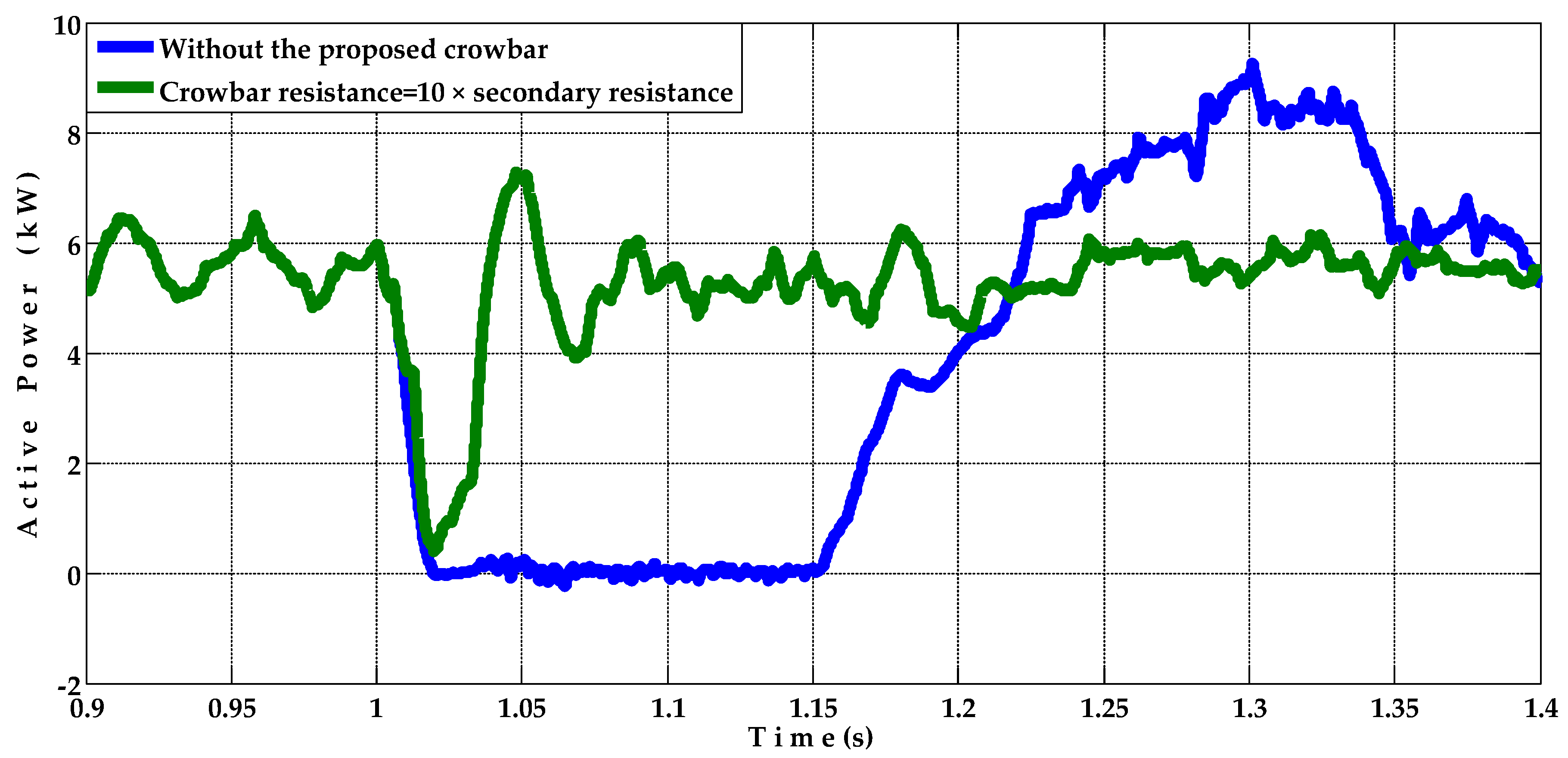
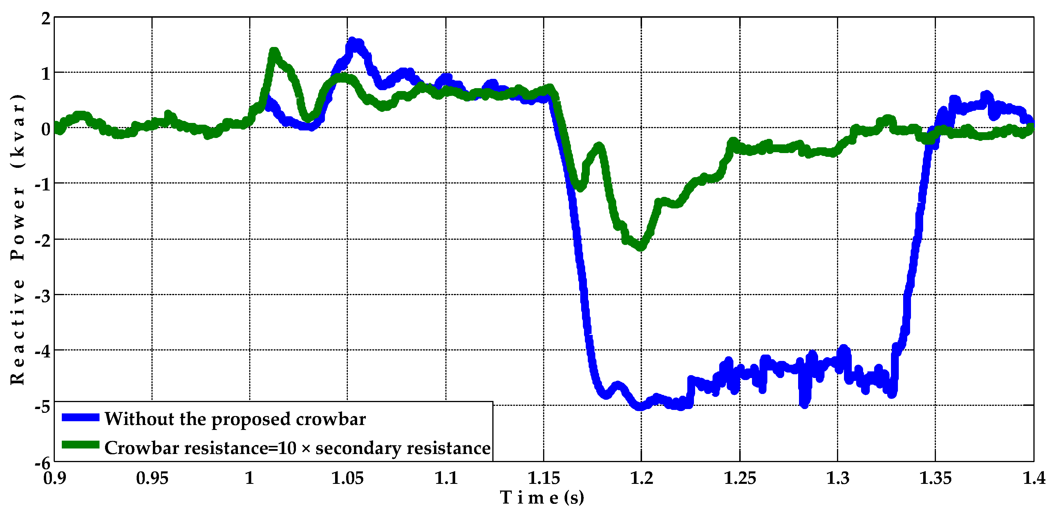
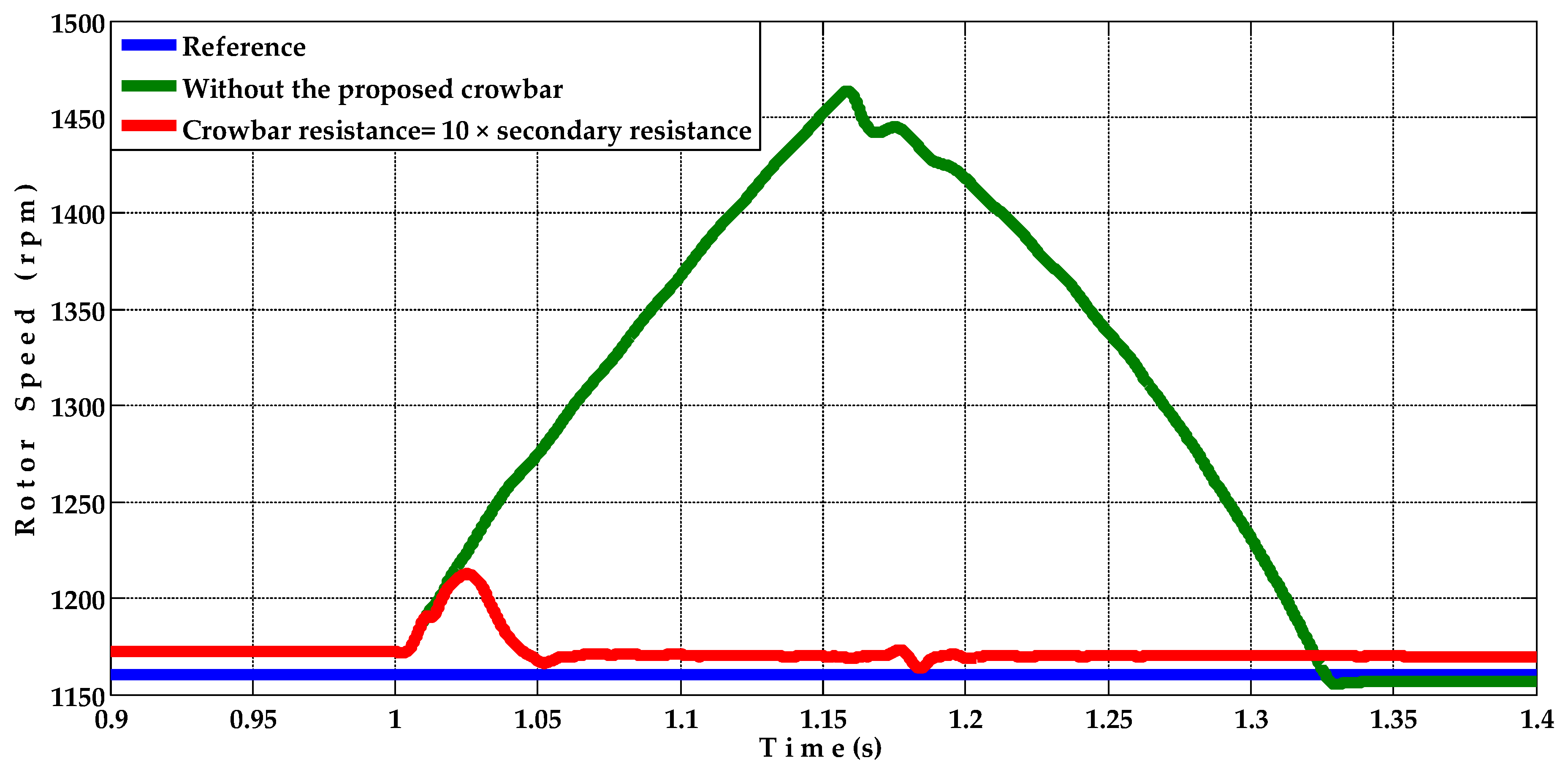
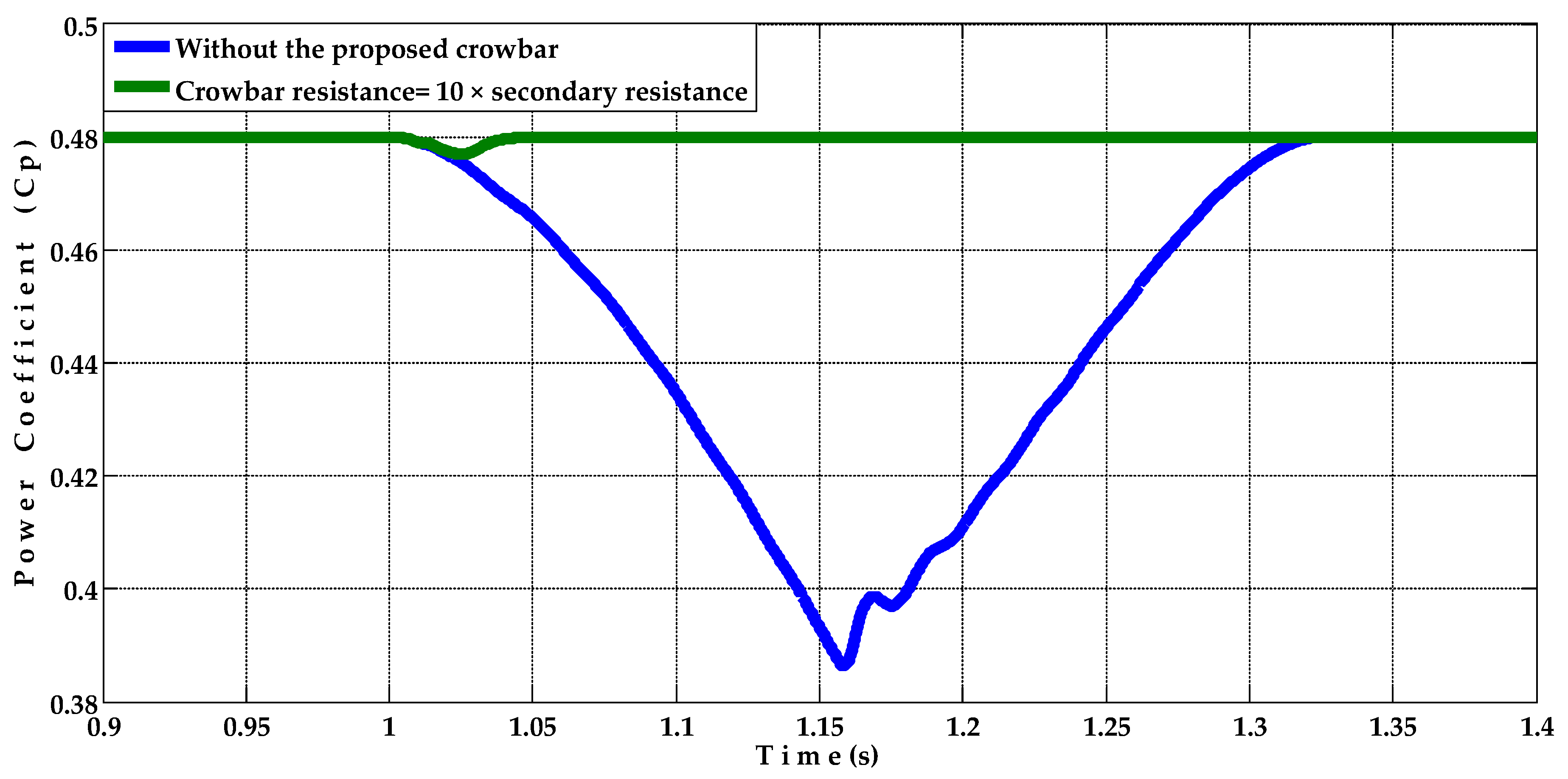
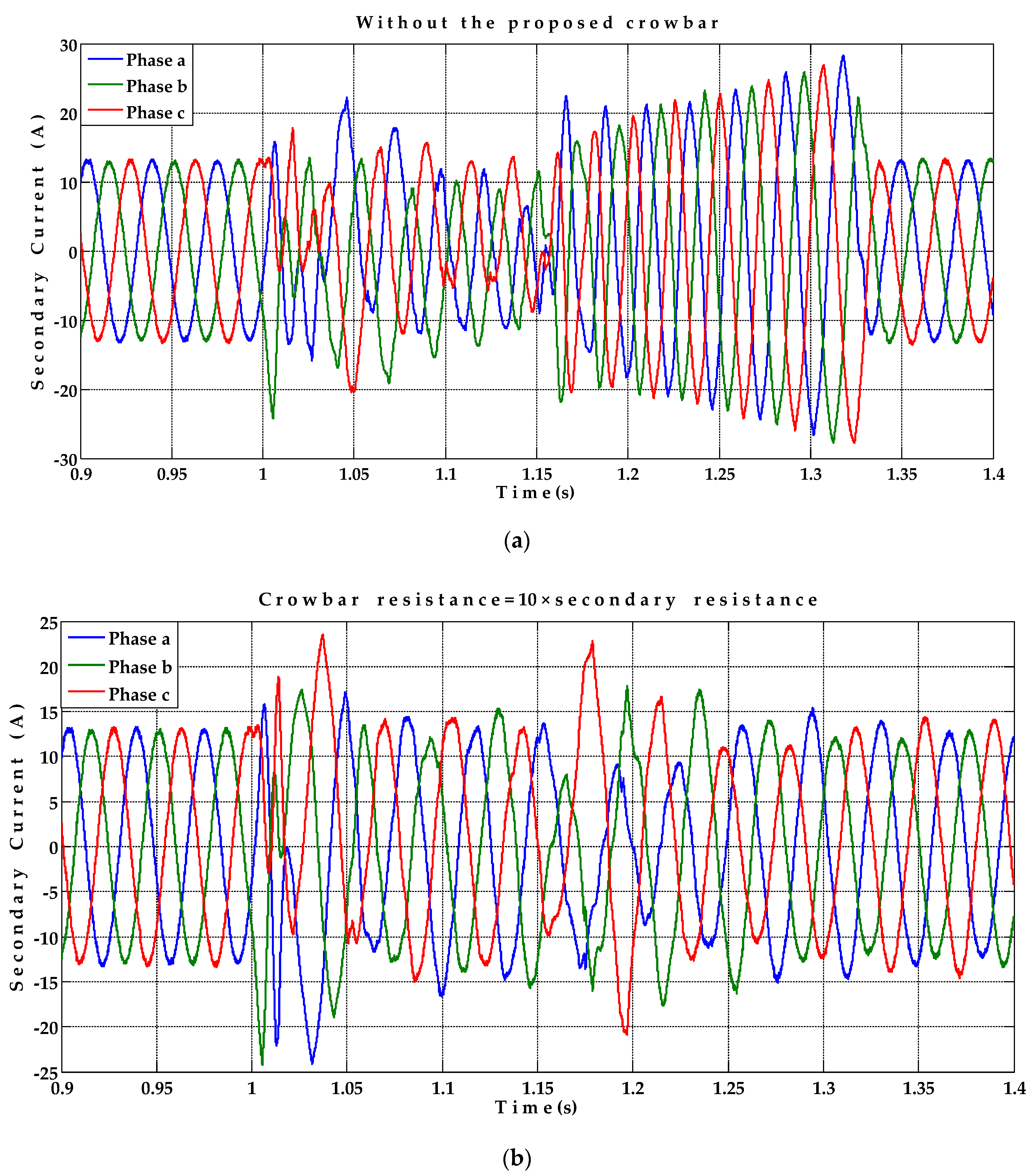
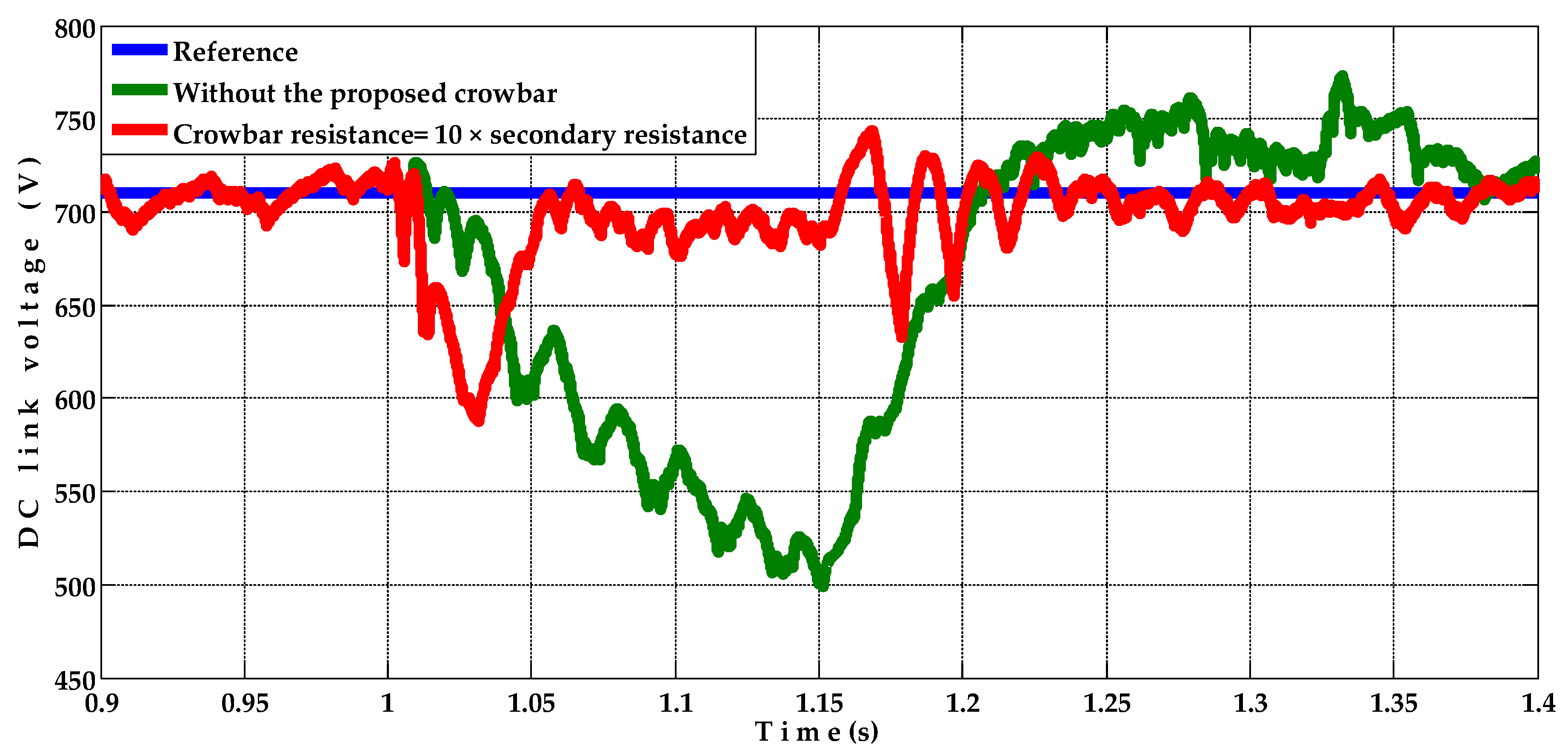
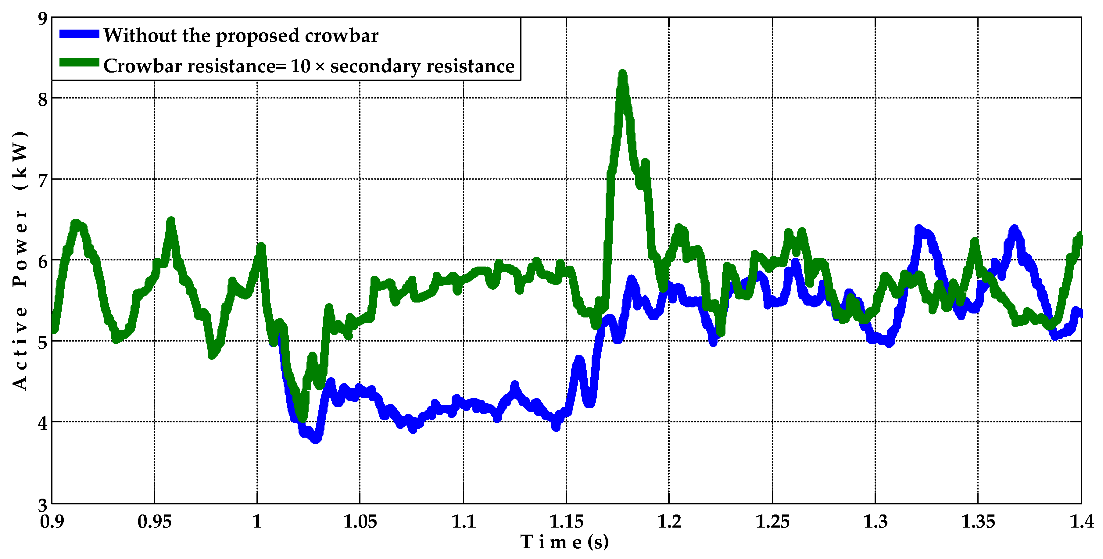
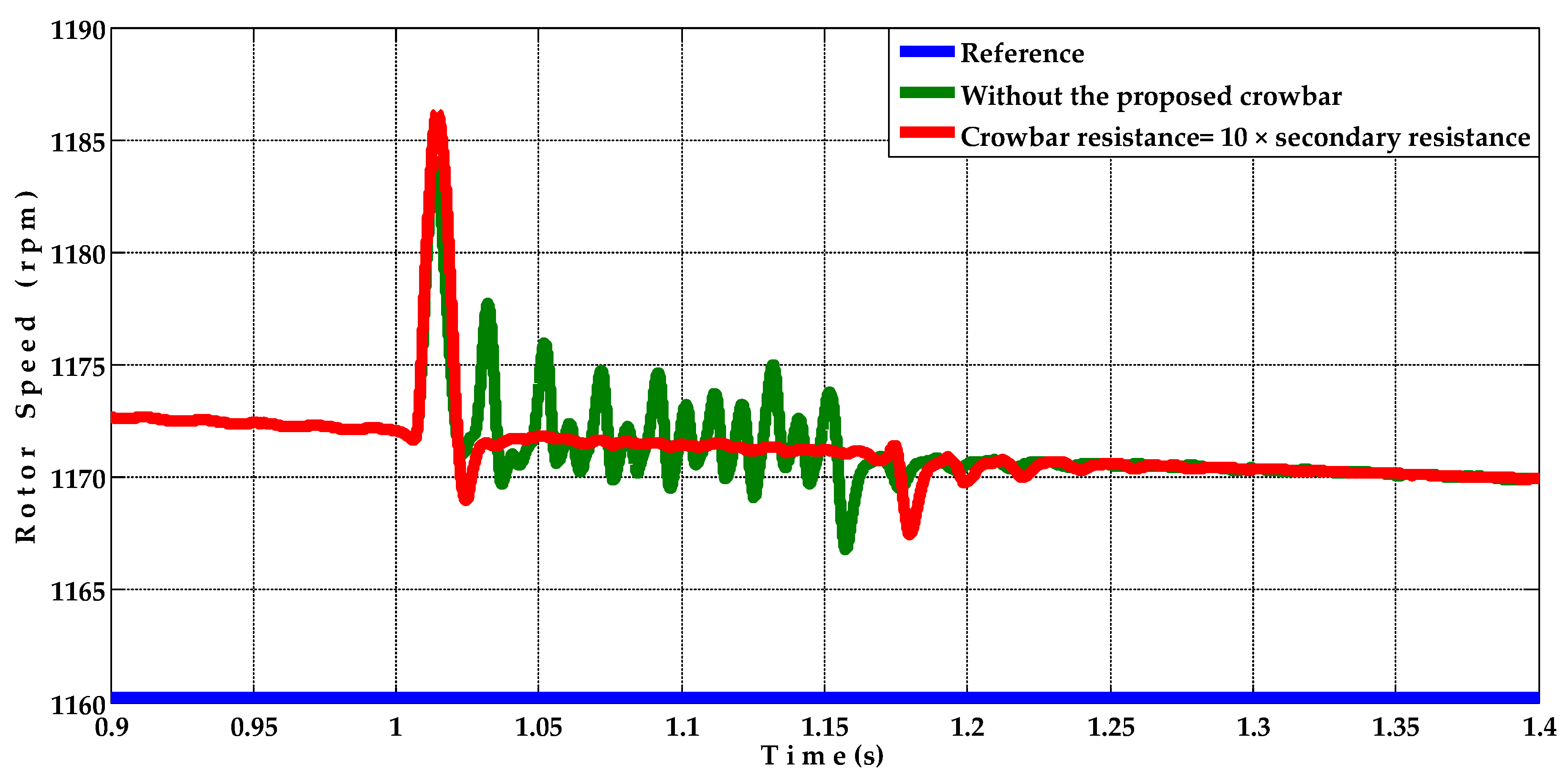
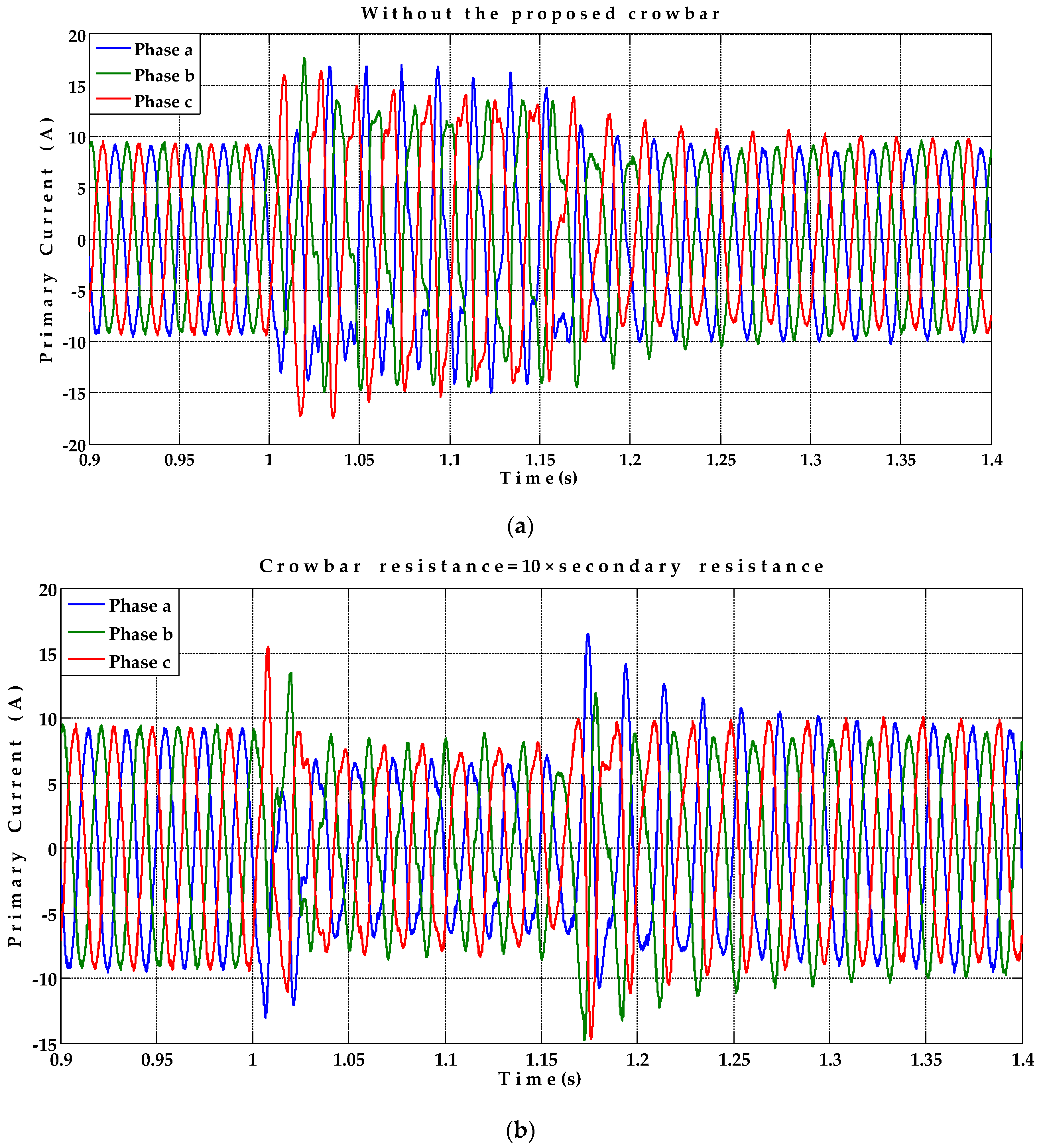
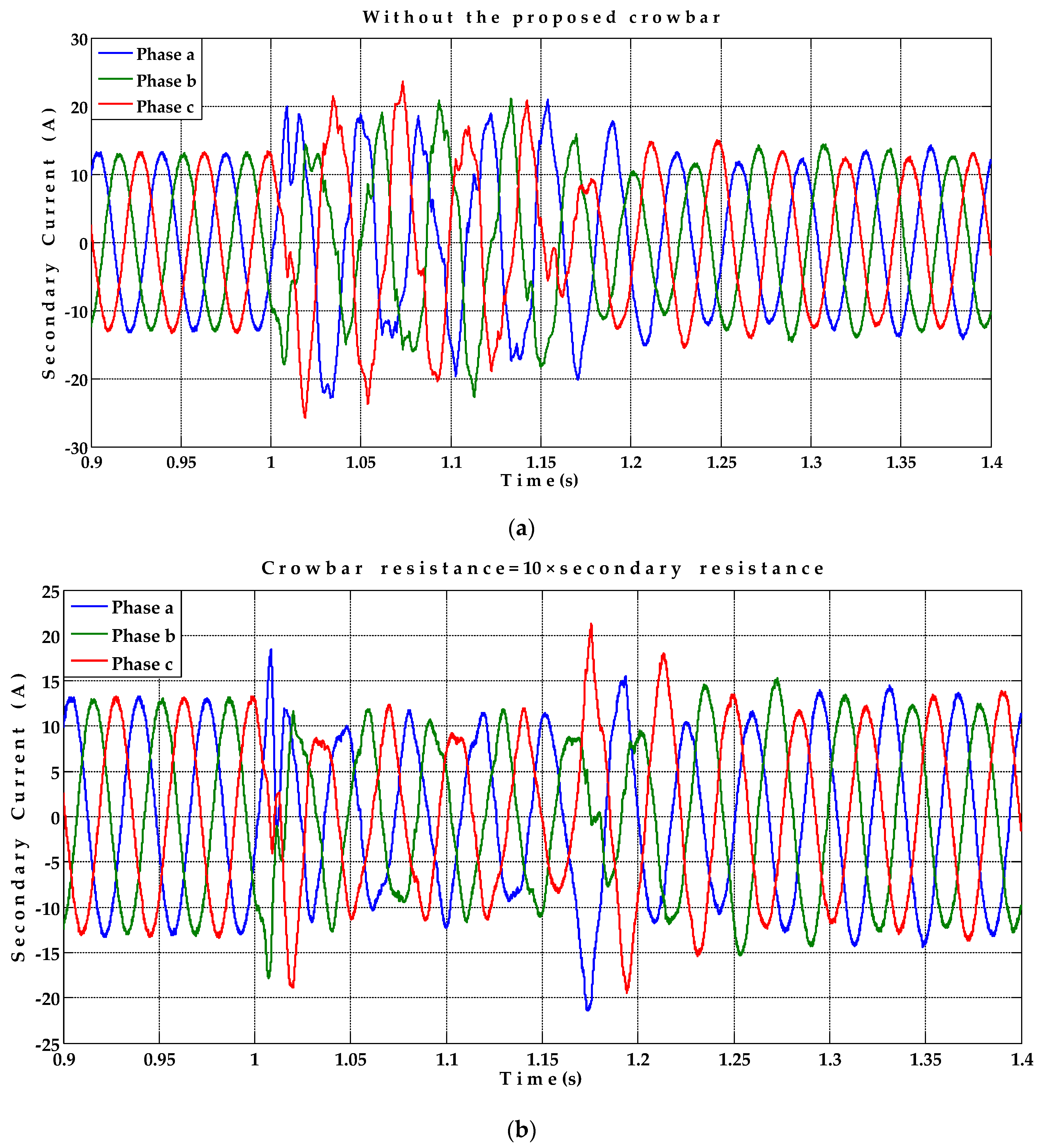
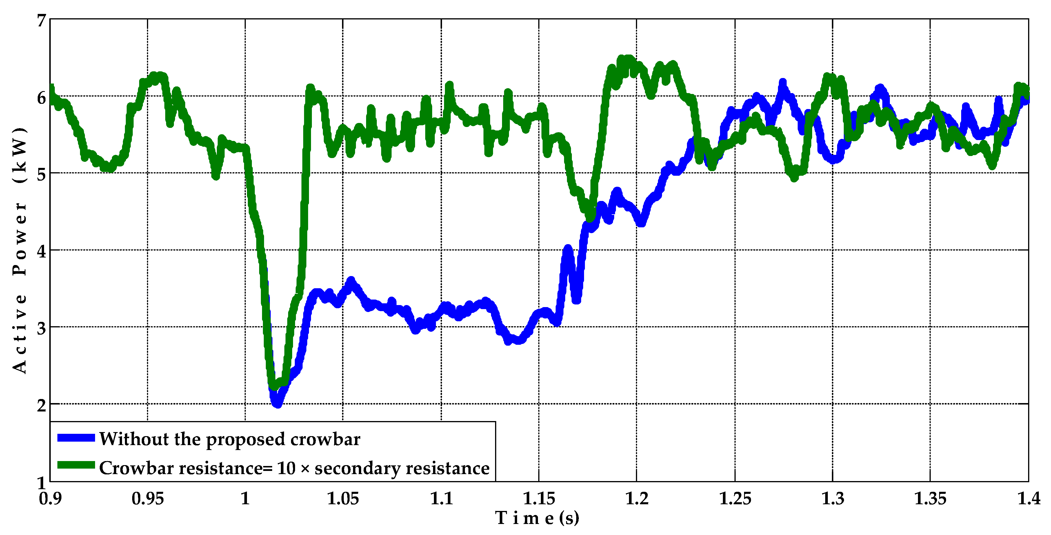
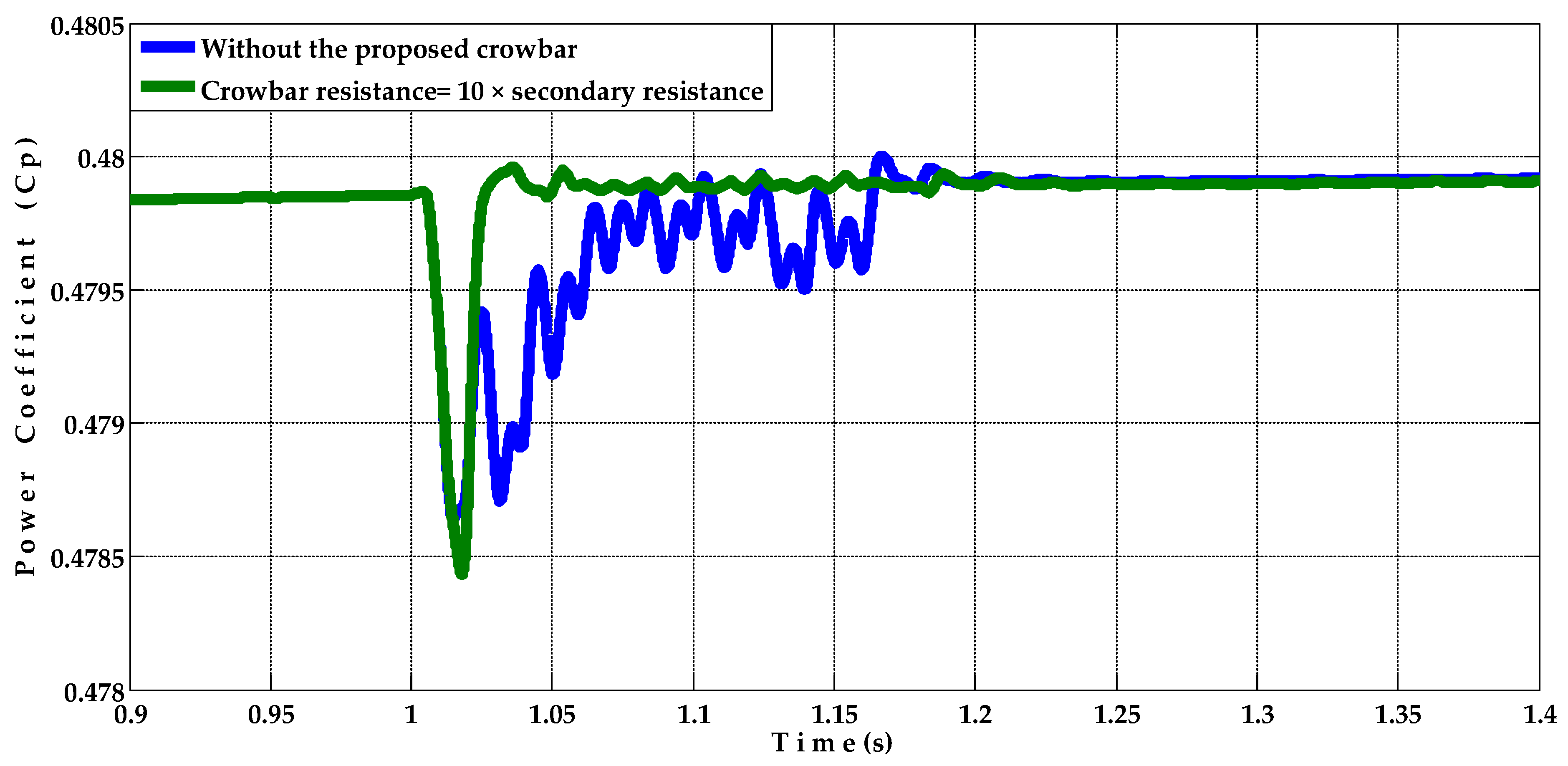
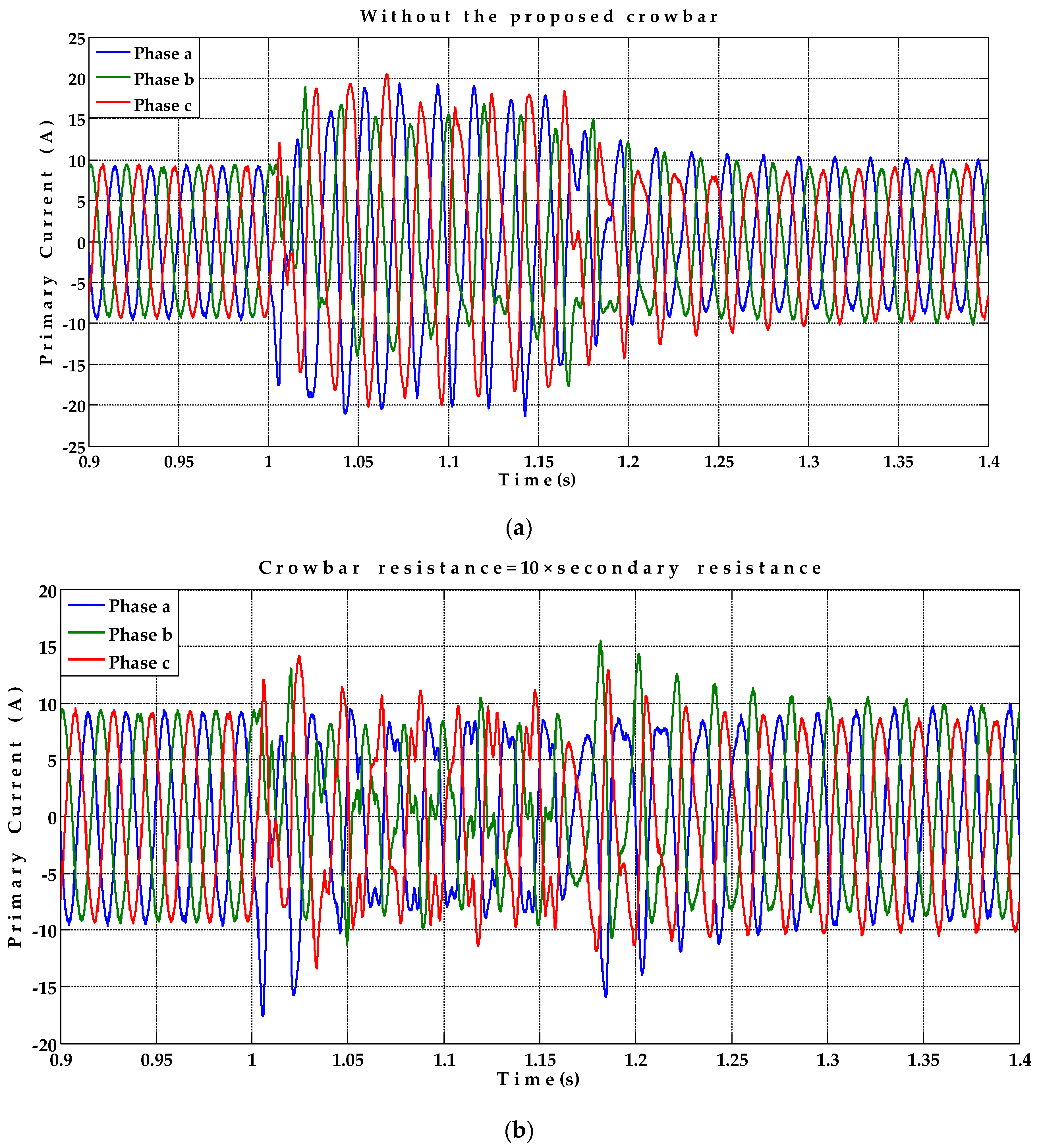
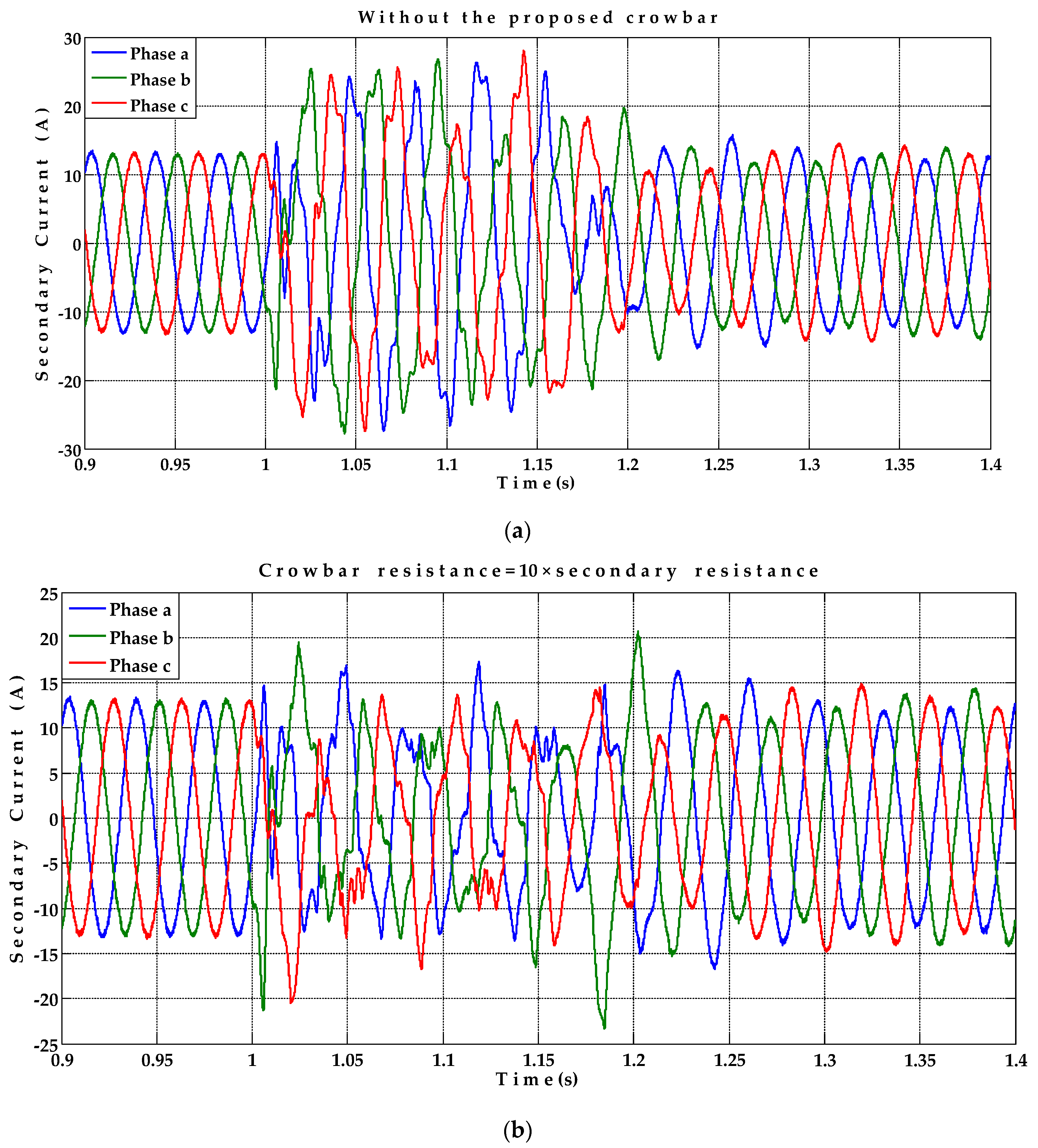
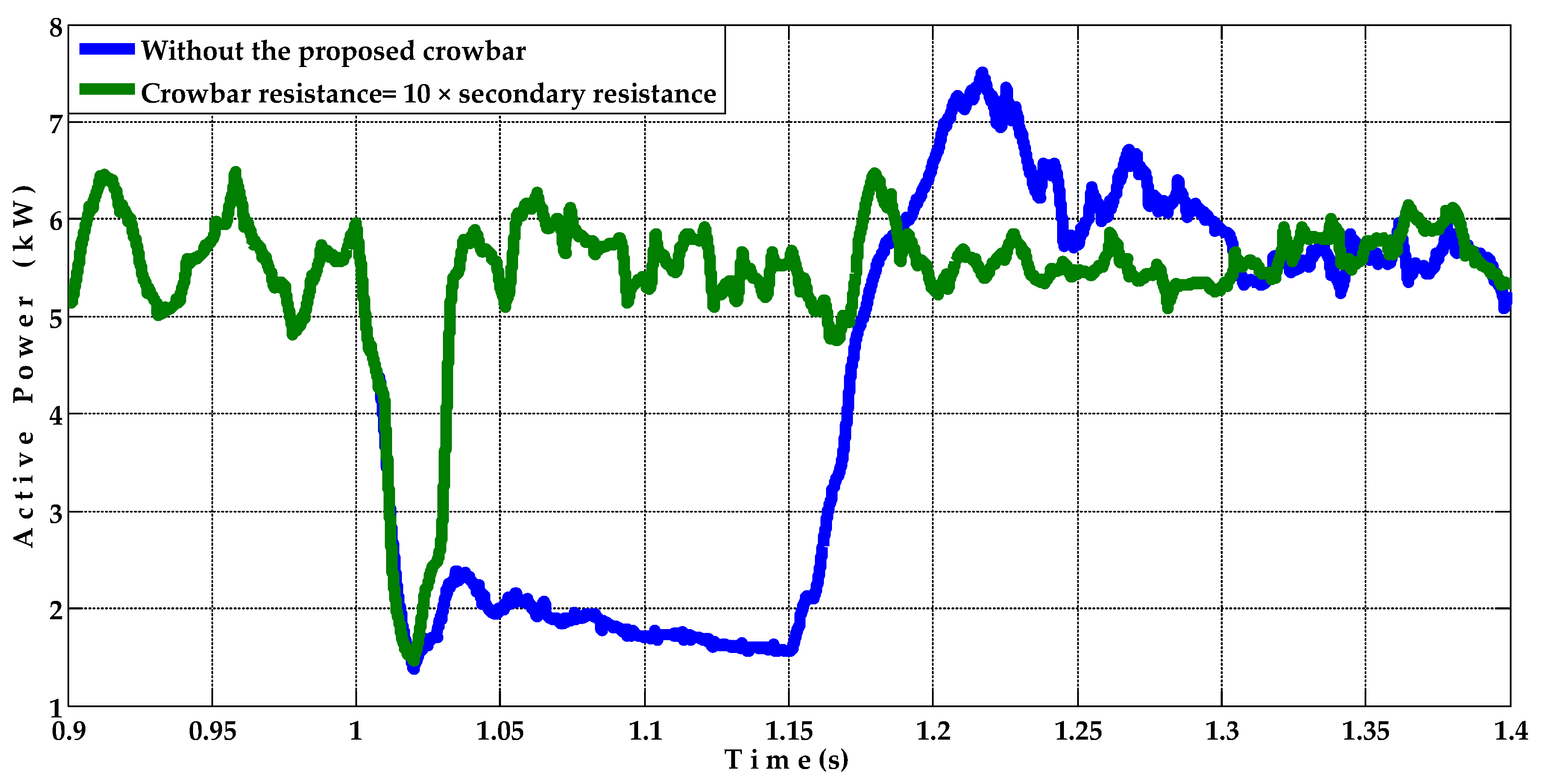
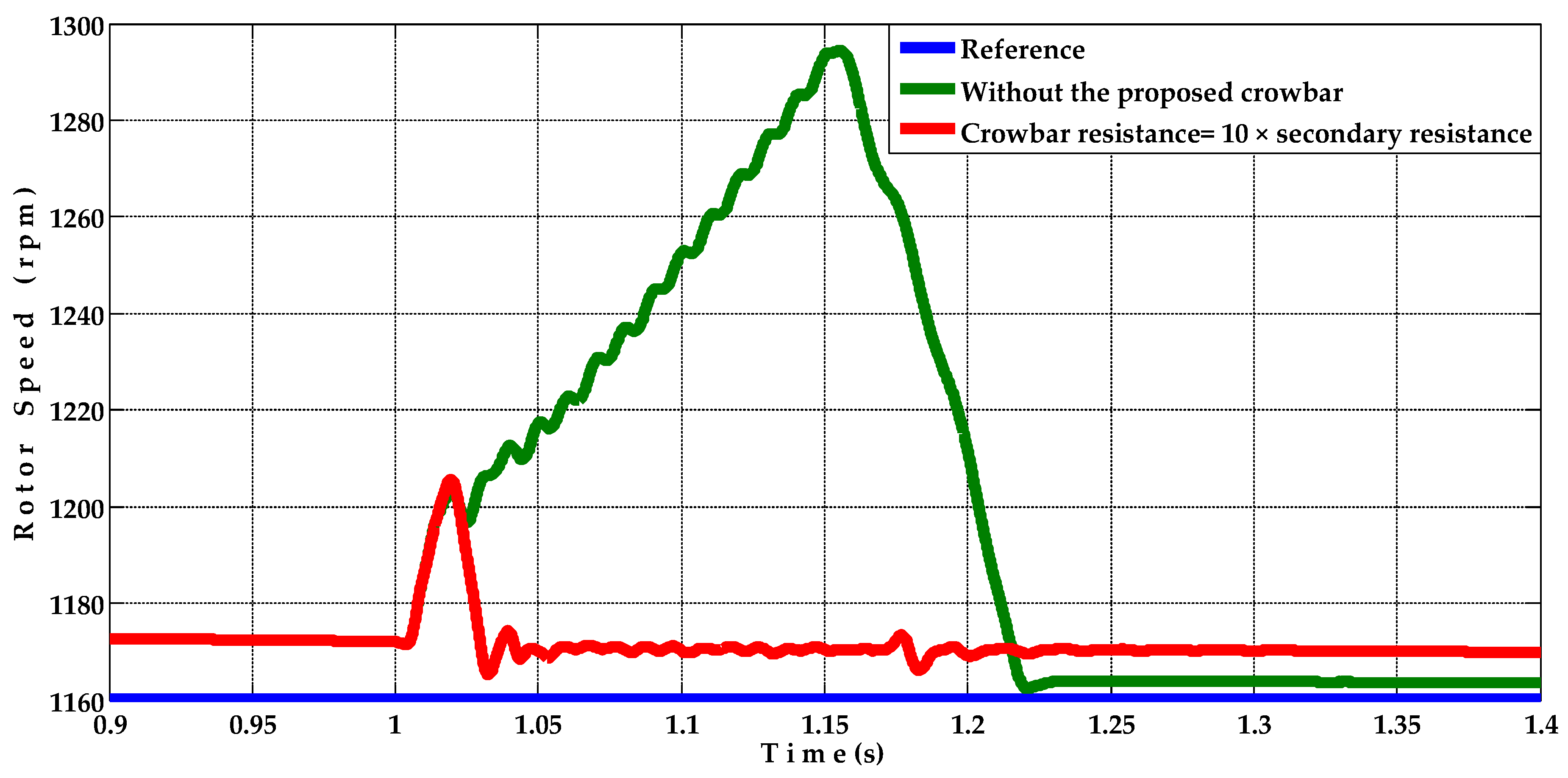
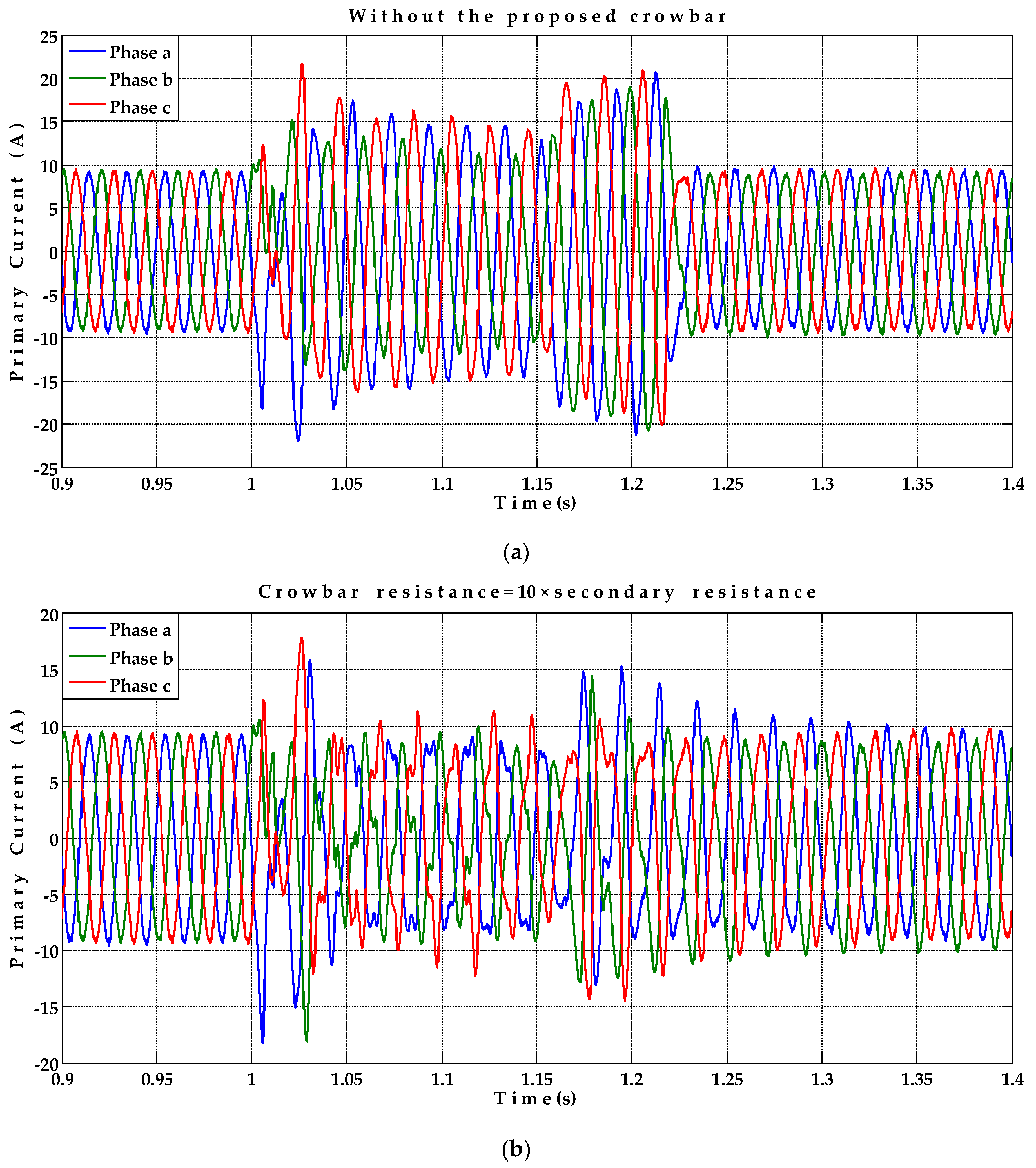
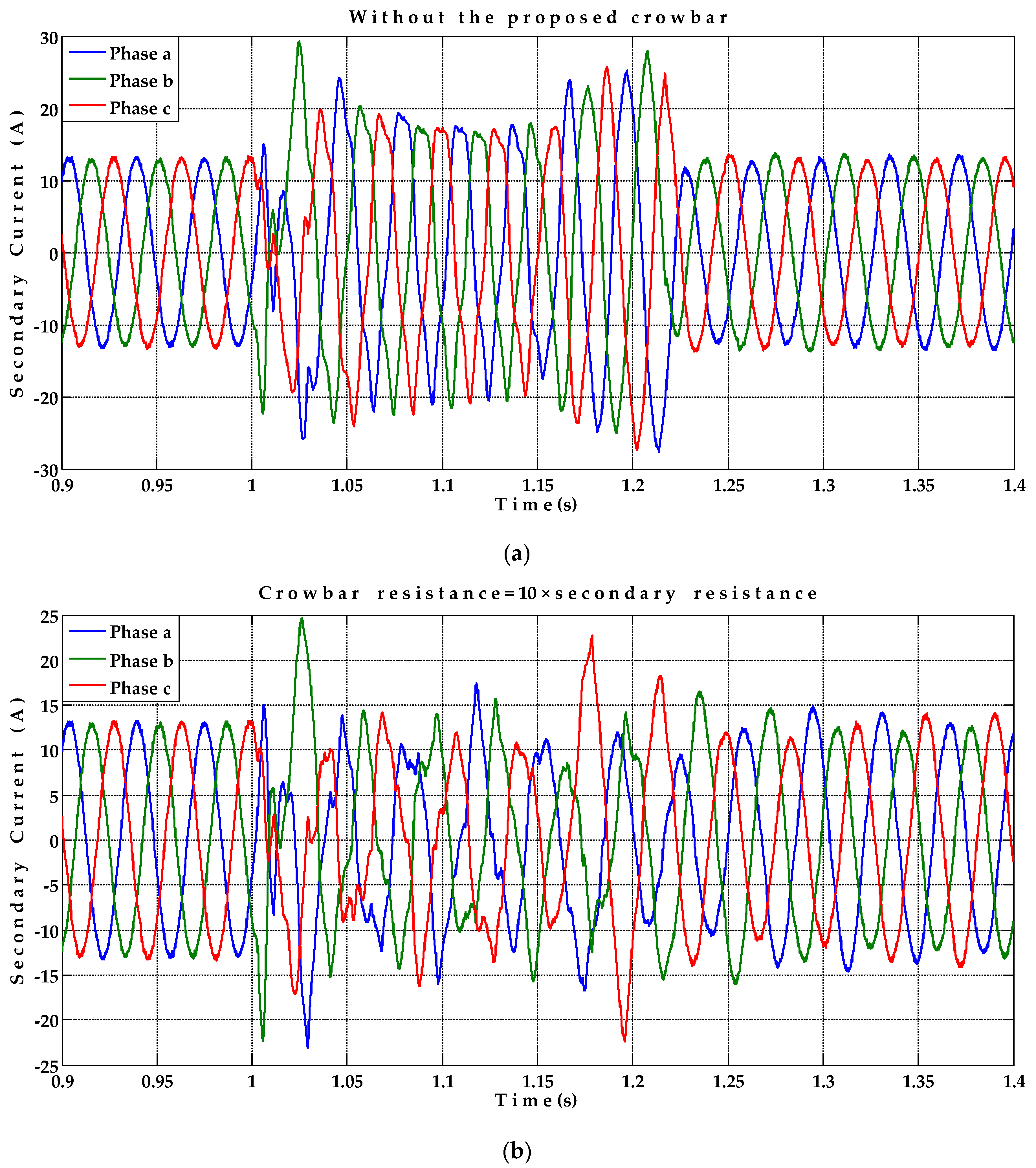
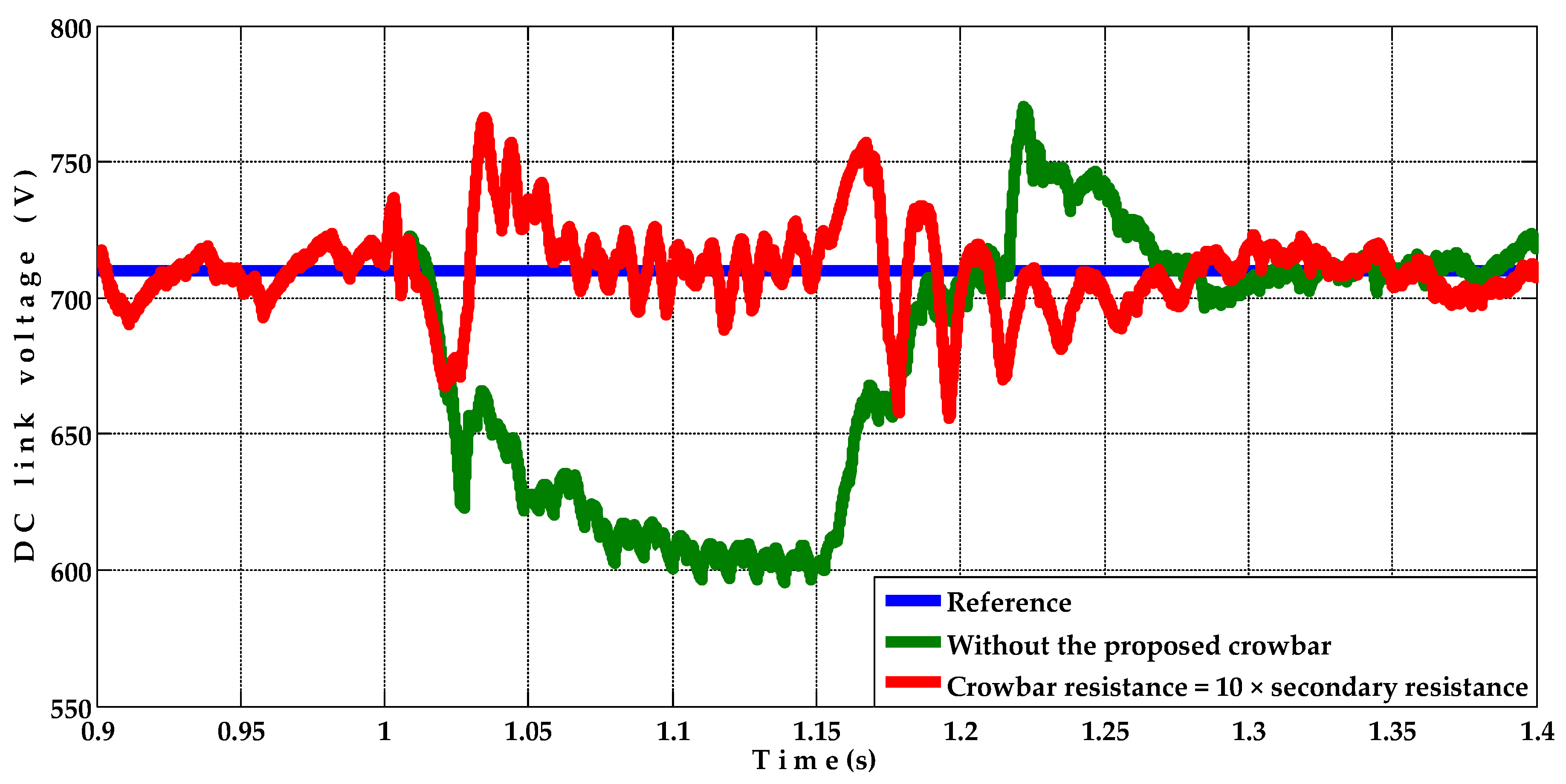
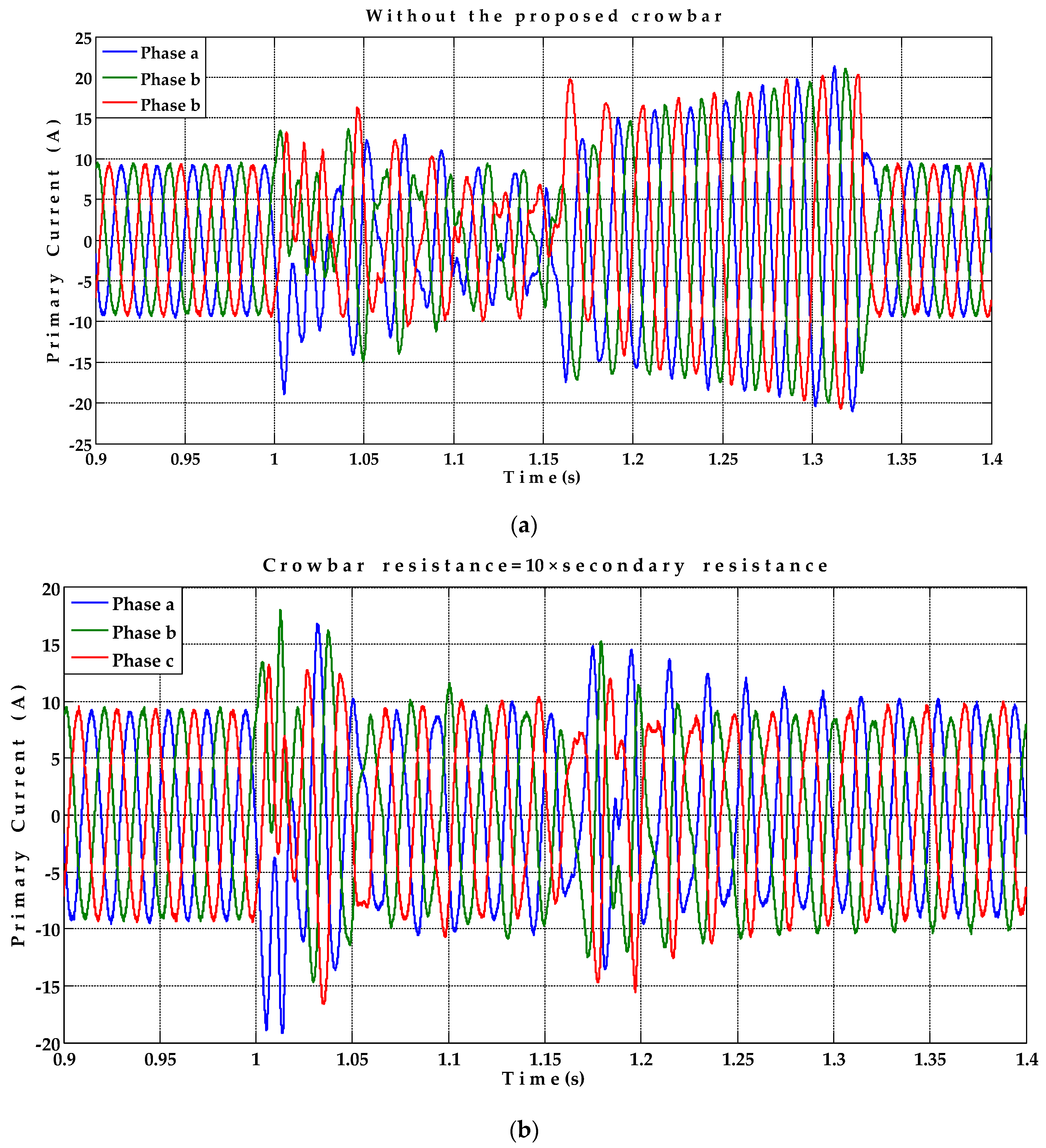
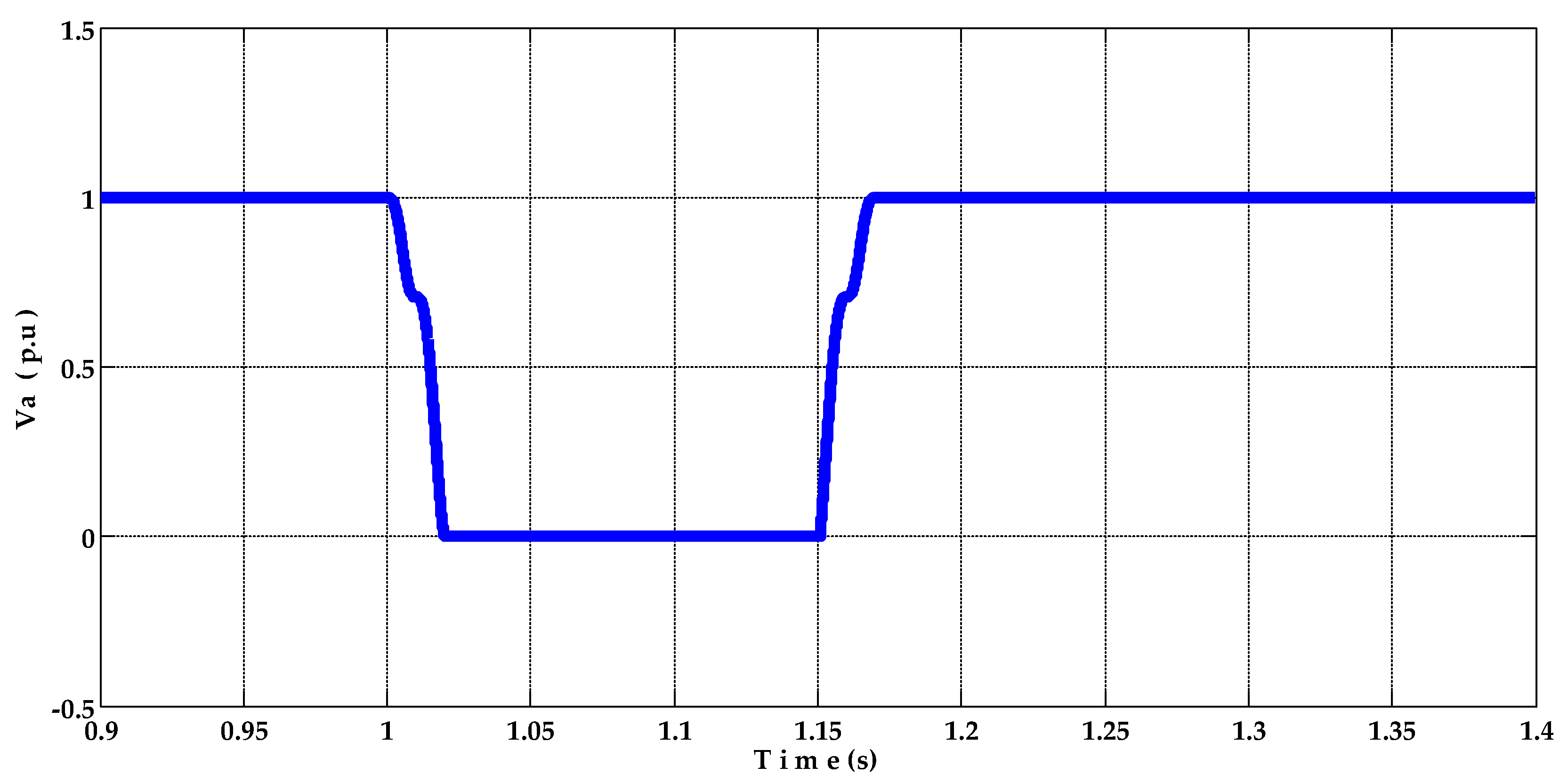
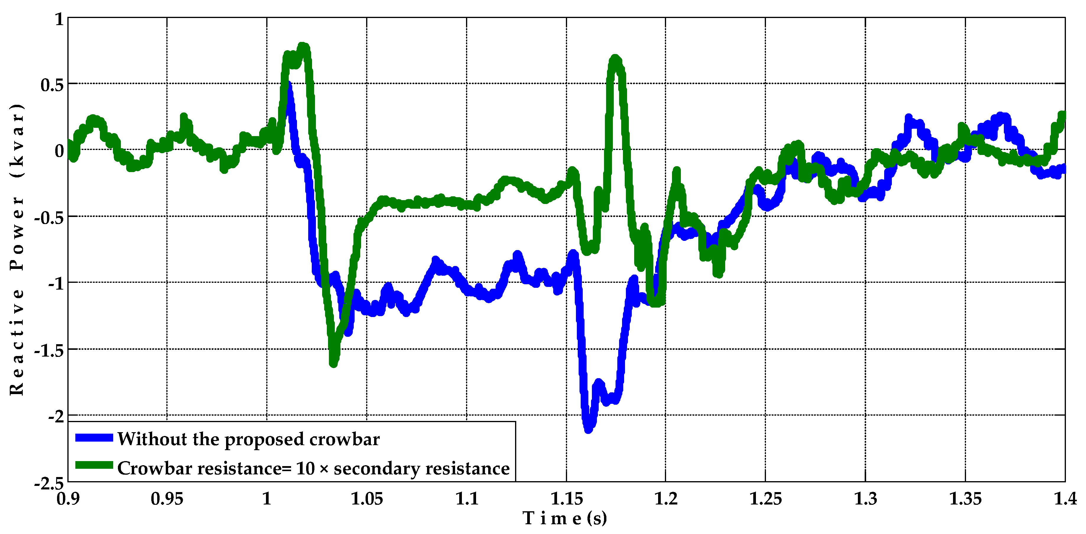
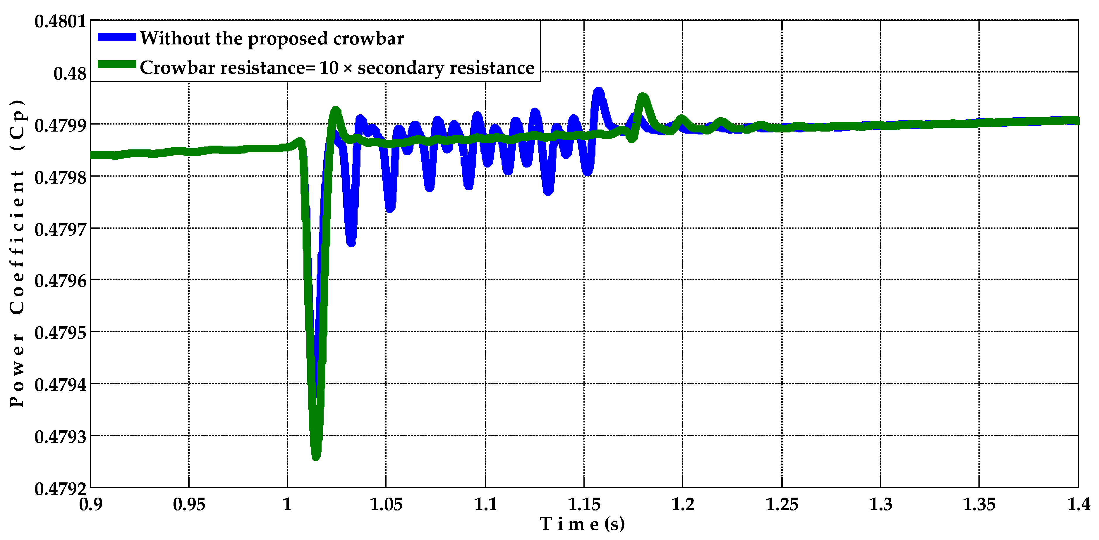
5.1. Symmetrical Fault (Three Line to Ground Fault)

The per unit rms terminal voltage of the BDFRG, as shown in Figure 5, at the instant of fault occurrence, the terminal voltage dropped to zero p.u. for 150 ms due to the occurrence of the studied three phase to ground fault; then, after fault clearance, the terminal voltage returns to its original value (1 p.u.).
The active power of the BDFRG (with and without using the proposed crowbar) is shown in Figure 6. As obvious in the case of “without using the proposed crowbar”, during the fault, the active power totally dropped to zero kW for 150 ms (fault duration time). In the case of using the proposed crowbar, during the fault, the active power was effectively improved and quickly returned to its pre-fault value.
The reactive power of the BDFRG (with and without the proposed crowbar) is shown in Figure 7. As shown, the reactive power was adjusted at zero value (unity power factor) before the fault occurrence. Following the clearance of the fault, in the case of “without using the proposed crowbar”, the absorbed reactive power, by the BDFRG from the grid, reached about 5.04 kvar. While in the case of using the proposed crowbar, after fault clearance, the absorbed reactive power was reduced to 2.165 kvar only and quickly improved until reaching its pre-fault value.
The rotor speed of the BDFRG (with and without using the proposed crowbar) is shown in Figure 8, which has a reference value equal to 1160 rpm. During the fault, in the case of “without using the proposed crowbar”, the rotor rapidly accelerated, then after fault clearance, the rotor speed reached about 1464 rpm, which led to a decrease in the power coefficient of the WT from 0.48 to less than 0.3846 as shown in Figure 9. In the case of using the proposed crowbar, the rotor speed increased instantaneously to about 1213 rpm only, then quickly improved.
The primary and secondary currents of the BDFRG (without and with using the proposed crowbar) are shown in Figure 10 and Figure 11 in the same order. In the case of “without using the proposed crowbar”, during the fault, both currents were increased for a certain period. After the fault clearance, the primary current was increased to about 212% (19.74 A) of the pre-fault value (9.32 A) and the secondary current was increased to about 216% (28.25 A) of the pre-fault value (13.05 A), while in the case of using the proposed crowbar, as shown in Figure 10b and Figure 11b, after the fault clearance, both the primary and secondary currents were effectively improved. As the primary current increased to (15.25 A), while the secondary current increased to (22.86 A) and then quickly both the primary and secondary currents were effectively improved.
The dc link voltage of the BDFRG (with and without using the proposed crowbar) is shown in Figure 12, which has a reference value equals to 710 V. Under the fault occurrence, in the case of “without using the proposed crowbar”, the dc link voltage was decreased to about 499.2 V. In the case of using the proposed crowbar, the dc link voltage decreased instantaneously to about 587.8 V only, then the dc link voltage improved and returned quickly to its pre-fault value.

5.2. Unsymmetrical Fault

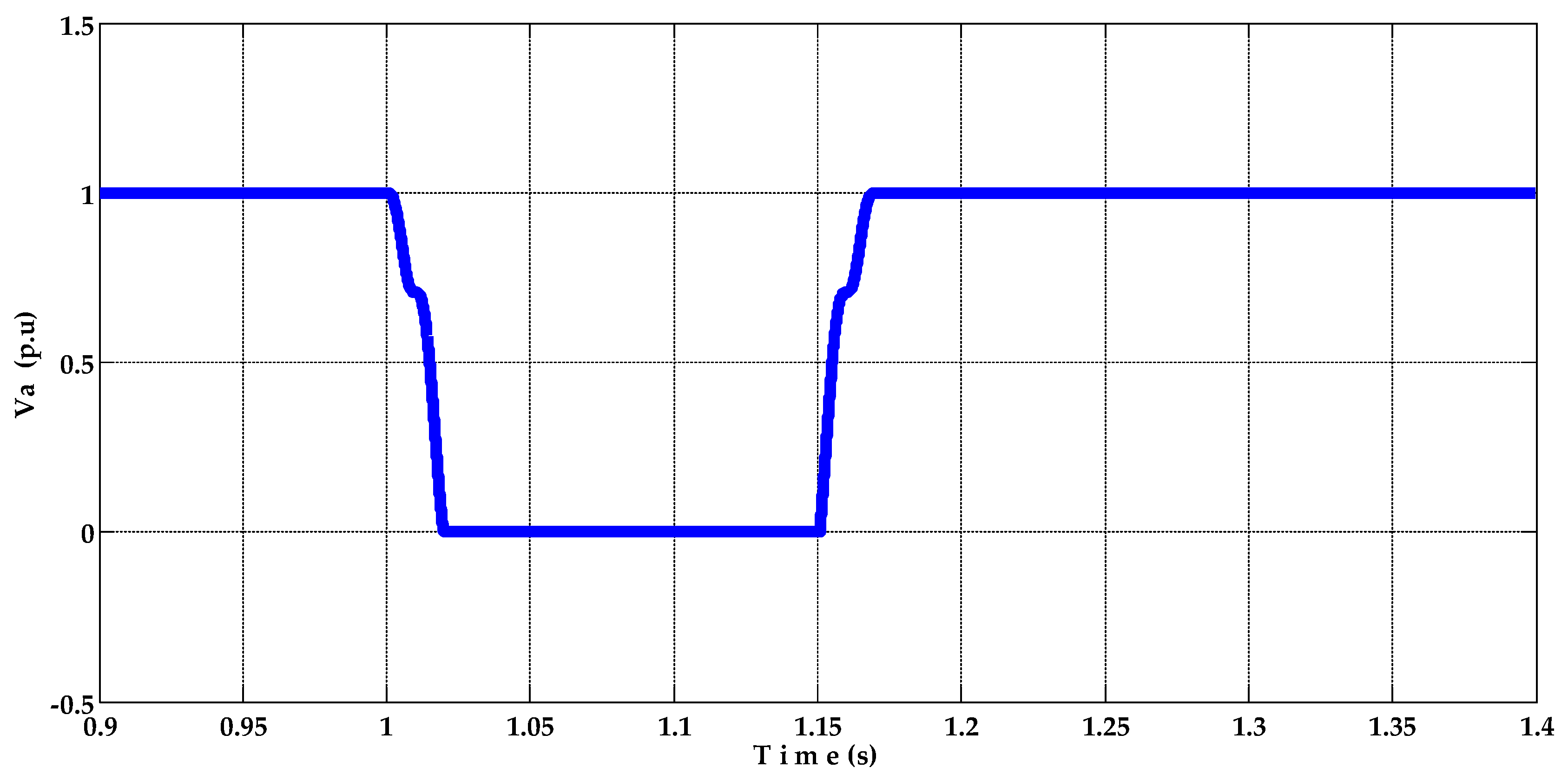
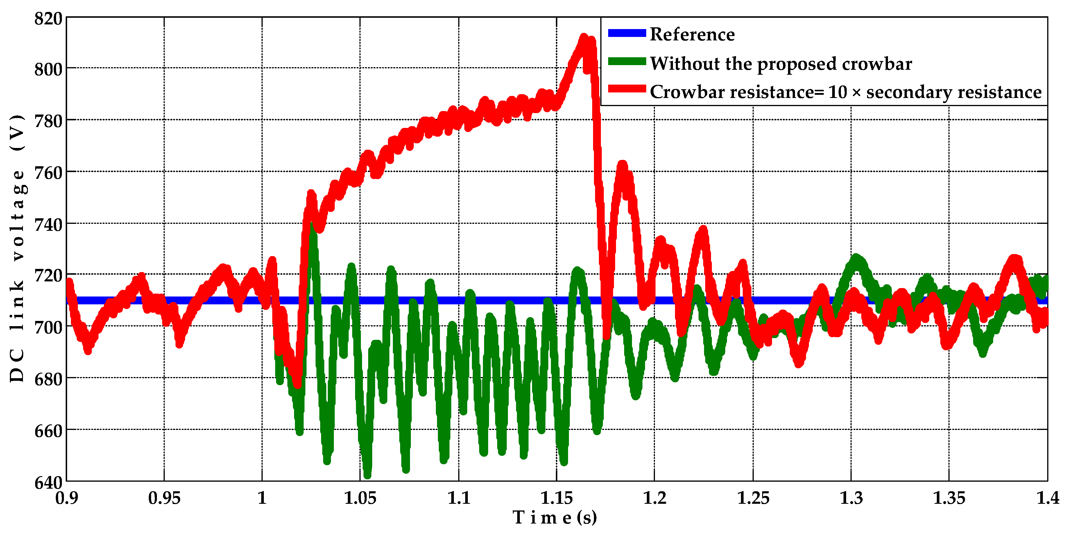
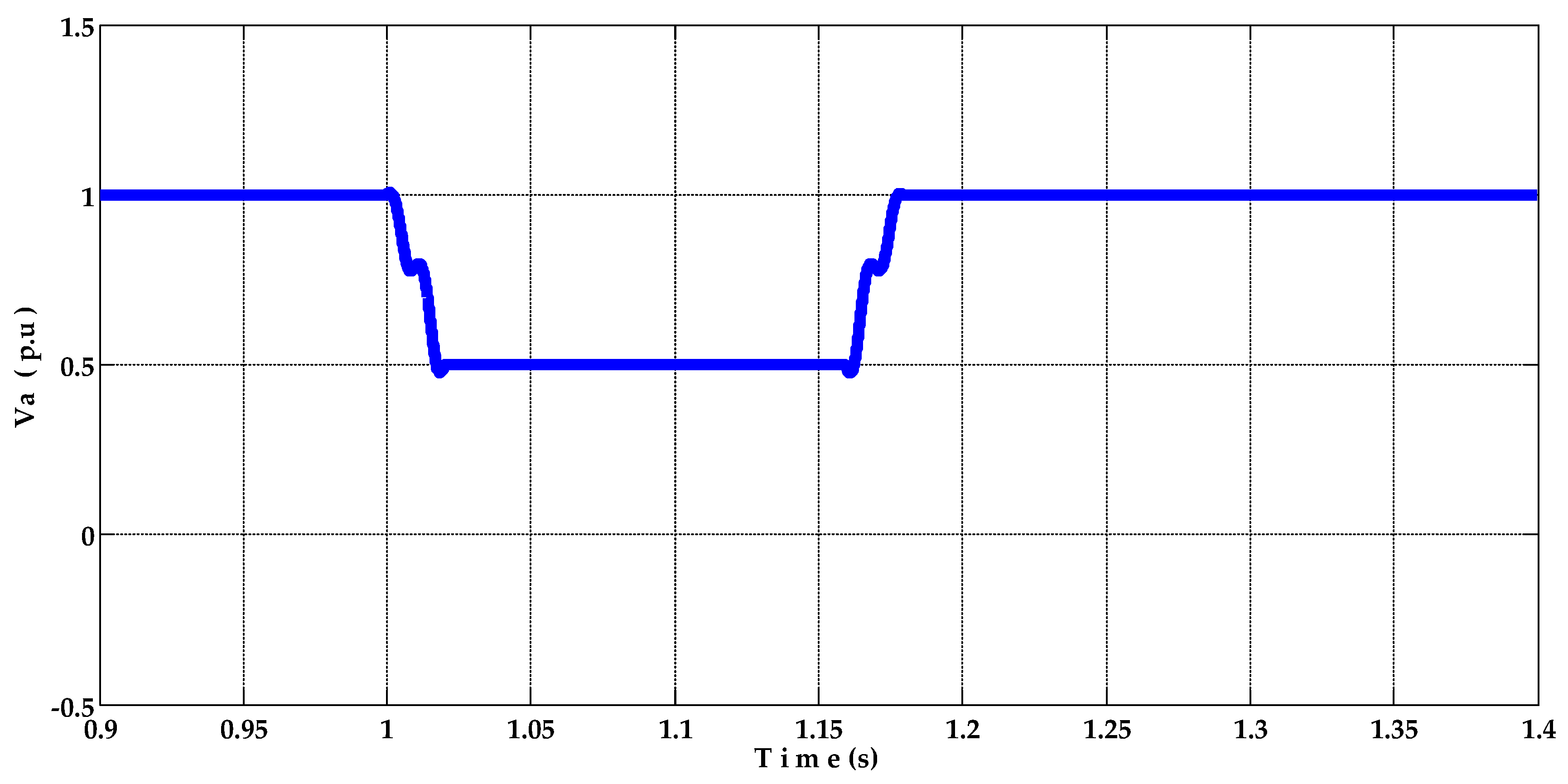
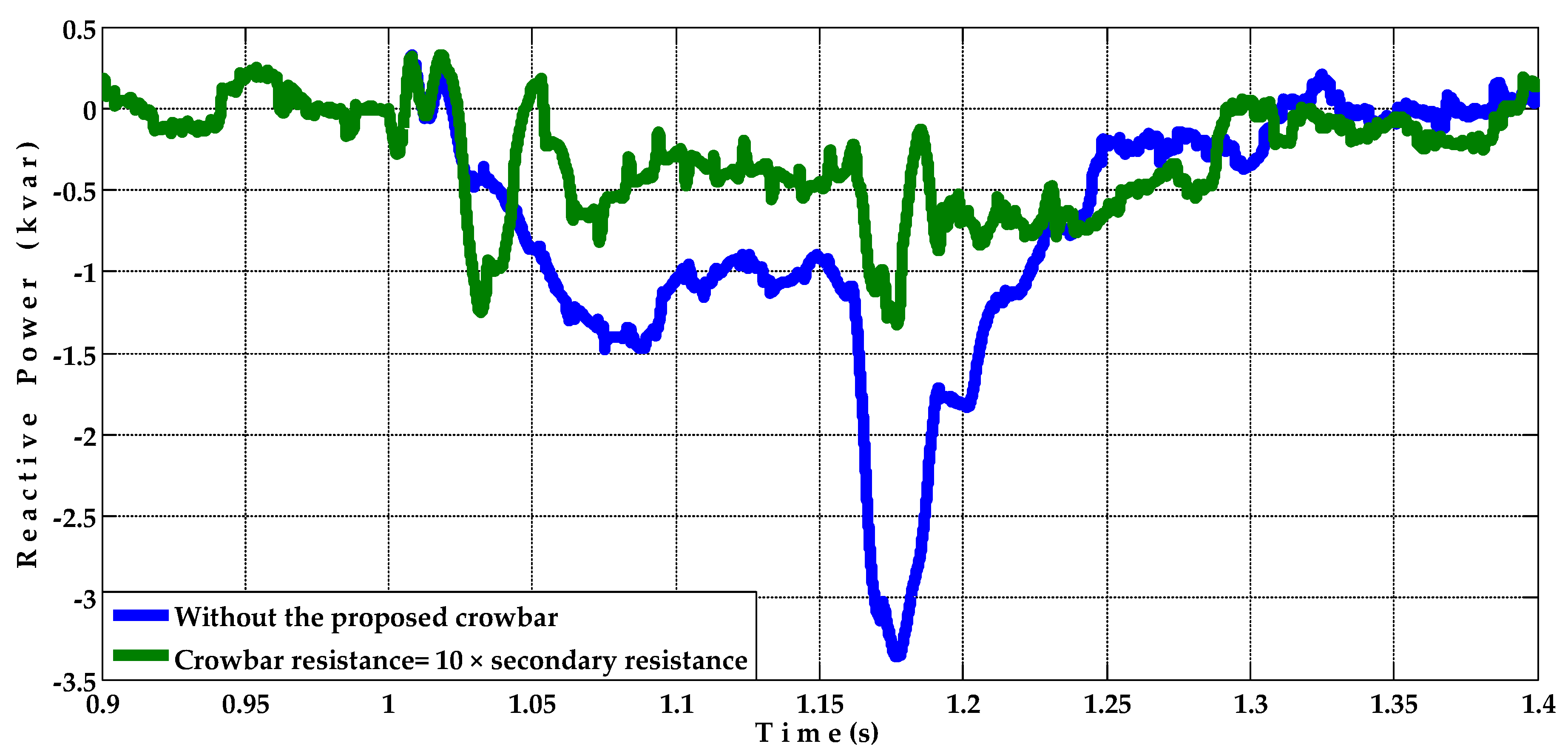
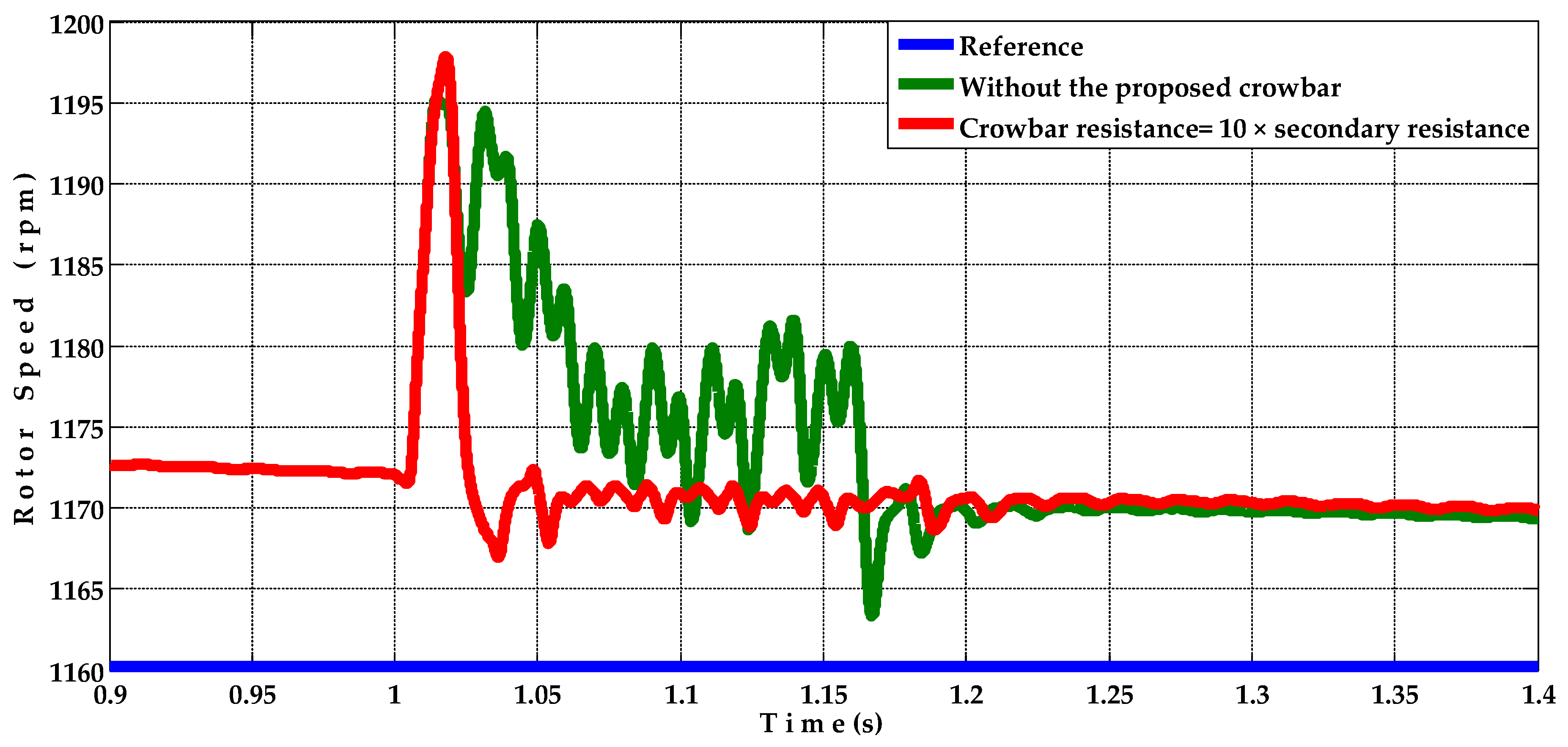
5.2.1. Single-Line to Ground Fault (The Fault Is Applied at Phase a)

The per unit rms terminal voltage of the BDFRG, as shown in Figure 13, at the instant of fault occurrence, the terminal voltage dropped to zero p.u. for 150 ms due to the occurrence of the studied single phase to ground fault, then after fault clearance, the terminal voltage returns to its original value (1 p.u.).
The active power of the BDFRG (with and without using the proposed crowbar) is shown in Figure 14. As obvious in the case of “without using the proposed crowbar”, during the fault, the active power dropped to 3.78 kW. In the case of using the proposed crowbar, during the fault, the active power was effectively improved and quickly returned to its pre-fault value.
The reactive power of the BDFRG (with and without using the proposed crowbar) is shown in Figure 15. As shown, the reactive power was adjusted at zero value (unity power factor) before the fault occurrence. Following the clearance of the fault, in the case of “without using the proposed crowbar”, the absorbed reactive power, by the BDFRG from the grid, reached about 2.115 kvar. In the case of using the proposed crowbar, after fault clearance, the absorbed reactive power was reduced to 1.158 kvar only and quickly improved until reaching its pre-fault value.
The rotor speed of the BDFRG (with and without using the proposed crowbar) is shown in Figure 16, which has a reference value equals to 1160 rpm. During fault, in the case of “without using the proposed crowbar”, the rotor rapidly accelerated and the rotor speed reached about 1184 rpm, which led to a decrease in the power coefficient of the WT from 0.48 to less than 0.4794 as shown in Figure 17. In the case of using the proposed crowbar, the rotor speed increased instantaneously to about 1186 rpm, but with damped oscillations than in the other case, then quickly improved.
The primary and secondary currents of the BDFRG (without and with using the proposed crowbar) are shown in Figure 18 and Figure 19 in the same order. In the case of “without using the proposed crowbar”, during the fault, both currents were increased, the primary current was increased to about 190% (17.68 A) of the pre-fault value (9.32 A) and the secondary current was increased to about 181% (23.58 A) of the pre-fault value (13.05 A), while in the case of using the proposed crowbar, as shown in Figure 18b and Figure 19b, during the fault, both the primary and secondary currents were effectively improved.
The dc link voltage of the BDFRG (with and without using the proposed crowbar) is shown in Figure 20, which has a reference value equal to 710 V. Under the fault occurrence, in the case of “without using the proposed crowbar”, the dc link voltage was decreased to about 642 V. In the case of using the proposed crowbar, the dc link voltage increased to about 800 V, but with damped oscillations than in the other case, then the dc link voltage improved and returned to its pre-fault value.

5.2.2. Line to Line Fault (The Fault Is Applied at Phases a and b)

The per unit rms terminal voltage of the BDFRG, as shown in Figure 21, at the instant of fault occurrence, the terminal voltage dropped to 0.5 p.u. for 150 ms due to the occurrence of the studied line to line fault, then after fault clearance, the terminal voltage returns to its original value (1 p.u.).
The active power of the BDFRG (with and without using the proposed crowbar) is shown in Figure 22. As obvious in the case of “without using the proposed crowbar”, during the fault, the active power dropped to 1.99 kW. In the case of using the proposed crowbar, during the fault, the active power was effectively improved and quickly returned to its pre-fault value.
The reactive power of the BDFRG (with and without using the proposed crowbar) is shown in Figure 23. As shown, the reactive power was adjusted at zero value (unity power factor) before the fault occurrence. Following the clearance of the fault, in the case of “without using the proposed crowbar”, the absorbed reactive power, by the BDFRG from the grid, reached about 3.364 kvar for a certain period. In the case of using the proposed crowbar, after fault clearance, the absorbed reactive power was reduced to 1.325 kvar only and quickly improved until reaching its pre-fault value.
The rotor speed of the BDFRG (with and without using the proposed crowbar) is shown in Figure 24, which has a reference value equal to 1160 rpm. During the fault, in the case of “without using the proposed crowbar”, the rotor rapidly accelerated and the rotor speed reached about 1196 rpm, which led to a decrease in the power coefficient of the WT from 0.48 to less than 0.4787 as shown in Figure 25. In the case of using the proposed crowbar, the rotor speed increased instantaneously to about 1198 rpm, but with damped oscillations than in the other case, then quickly improved.
The primary and secondary currents of the BDFRG (without and with using the proposed crowbar) are shown in Figure 26 and Figure 27 in the same order. In the case of “without using the proposed crowbar”, during the fault, both currents were increased; the primary current was increased to about 220% (20.47 A) of the pre-fault value (9.32 A) and the secondary current was increased to about 215% (28.04 A) of the pre-fault value (13.05 A), while in the case of using the proposed crowbar, as shown in Figure 26b and Figure 27b, during the fault, both the primary and secondary currents were effectively improved.
The dc link voltage of the BDFRG (with and without using the proposed crowbar) is shown in Figure 28, which has a reference value equal to 710 V. Under the fault occurrence, in the case of “without using the proposed crowbar”, the dc link voltage was decreased to about 584 V. In the case of using the proposed crowbar, the dc link voltage, during the fault, at first decreased to 690.5 V and then increased to about 777 V, then the dc link voltage improved and returned to its pre-fault value.

5.2.3. Double Line to Ground Fault (The Fault Is Applied at Phases a and b)

The per unit rms terminal voltage (Va) of the BDFRG, as shown in Figure 29, at the instant of fault occurrence, the terminal voltage dropped to zero p.u. for 150 ms due to the occurrence of the studied double line to ground fault; then, after fault clearance, the terminal voltage returns to its original value (1 p.u.).
The active power of the BDFRG (with and without using the proposed crowbar) is shown in Figure 30. As obvious in the case of “without using the proposed crowbar”, during the fault, the active power dropped to 1.373 kW. In the case of using the proposed crowbar, during the fault, the active power was effectively improved and quickly returned to its pre-fault value.
The reactive power of the BDFRG (with and without using the proposed crowbar) is shown in Figure 31. As shown, the reactive power was adjusted at zero value (unity power factor) before the fault occurrence. Following the clearance of the fault, in the case of “without using the proposed crowbar”, the absorbed reactive power, by the BDFRG from the grid, reached about 5.15 kvar for a certain period. In the case of using the proposed crowbar, after fault clearance, the absorbed reactive power was reduced to 1.63 kvar only and quickly improved until reaching its pre-fault value.
The rotor speed of the BDFRG (with and without using the proposed crowbar) is shown in Figure 32, which has a reference value equals to 1160 rpm. During the fault, in the case of “without using the proposed crowbar”, the rotor rapidly accelerated; then, after fault clearance, the rotor speed reached about 1294 rpm, which led to a decrease in the power coefficient of the WT from 0.48 to less than 0.4605 as shown in Figure 33. While in the case of using the proposed crowbar, the rotor speed increased instantaneously to about 1206 rpm, then quickly improved.
The primary and secondary currents of the BDFRG (without and with using the proposed crowbar) are shown in Figure 34 and Figure 35 in the same order. In the case of “without using the proposed crowbar”, during the fault, both currents were increased; the primary current was increased to about 233% (21.69 A) of the pre-fault value (9.32 A) and the secondary current was increased to about 224% (29.29 A) of the pre-fault value (13.05 A), while in the case of using the proposed crowbar, as shown in Figure 34b and Figure 35b, during the fault, both the primary and secondary currents were effectively improved.
The dc link voltage of the BDFRG (with and without using the proposed crowbar) is shown in Figure 36, which has a reference value equal to 710 V. Under the fault occurrence, in the case of “without using the proposed crowbar”, the dc link voltage was decreased to about 595.5 V. In the case of using the proposed crowbar, the dc link voltage, during the fault, at first decreased to 667.2 V and then increased to about 766.4 V; then, the dc link voltage improved and returned to its pre-fault value.

6. Conclusions

To improve the capability of the BDFRG WTs to satisfy the grid code requirements concerning remaining the wind turbines connected to the grid under the occurrence of grid disturbances, many complex and expensive techniques were used such as using ANFIS control systems. This work proposes a new controllable crowbar as a new simple and economic solution to enhance the performance of the BDFRG WT under the occurrence of heavy faults. To examine the efficacy of the proposed controllable crowbar, the performance of the BDFRG WT under the occurrence of heavy different types of faults was studied twice, one without using the proposed controllable crowbar and the other with using it. To ensure that the proposed crowbar would be examined under the most extreme fault conditions, the location of the studied faults was chosen at the beginning of the transmission line next to the “wind farm” main point of common coupling. Not only that, but also to ensure accurate monitoring of the total actual performance of the BDFRG WT under the studied faults, all the protection system devices were deactivated. The terminal voltage, active power, reactive power, rotor speed, power coefficient, primary current of the BDFRG, secondary current of the BDFRG and DC link voltage were monitored and analyzed. Simulation results showed that in the case of fault occurrence without using the proposed controllable crowbar, all the monitored parameters were badly affected and the BDFRG WT would be rapidly disconnected from the network. On the other hand, simulation results showed that the proposed controllable crowbar effectively improved all the monitored parameters and enabled the studied BDFRG WT to remain in service under the studied faults.

Author Contributions

Conceptualization, M.R. and M.N.; methodology, M.R. and M.N.; software, M.R. and M.N.; validation, M.R., M.N. and A.E.-S.; formal analysis, M.R. and M.N.; investigation, M.R., M.N. and A.E.-S.; resources, M.R., A.E.-S. and M.N.; data curation, M.R. and M.N.; writing—original draft preparation, M.R. and M.N.; writing—review and editing, M.R., M.N. and B.H., A.E.-S.; visualization, M.R.; supervision, A.E.-S., M.R. and B.H.; project administration, A.E.-S.; funding acquisition, A.E.-S. All authors have read and agreed to the published version of the manuscript.

Funding

This research received no external funding.

Institutional Review Board Statement

Not applicable.

Informed Consent Statement

Not applicable.

Data Availability Statement

The data presented in this study are available on request from the corresponding author. The data are not publicly available due to their large size.

Conflicts of Interest

The authors declare no conflict of interest.

Nomenclature

List of Abbreviations
BDFRGBrushless Doubly Fed Reluctance Generator
VSWTVariable Speed Wind Turbine
WTWind Turbine
WECSWind Energy Conversion System
SCIGSquirrel Cage Induction Generator
DFIGDoubly Fed Induction Generator
BDFMBrushless Doubly Fed Machine
BDFIMBrushless Doubly Fed Induction Machine
BDFRMBrushless Doubly Fed Reluctance Machine
BDFIGBrushless Doubly Fed Induction Generator
MSCMachine Side Converter
GSCGrid Side Converter
MPPTMaximum Power Point Tracking
SPWMSinusoidal Pulse Width Modulation
IFOC Indirect Field Oriented Control
PLLPhase-Locked Loop
RMSRoot Mean Square
ANFISAdaptive Neuro Fuzzy Inference System
List of Symbols
ω speed of reference frame of power winding
ω relectrical speed of rotor
vdpdirect voltage component for power winding
vqpquadrature voltage component for power winding
vdcdirect voltage component for control winding
vqcquadrature voltage component for control winding
rpresistance of power winding
rcresistance of control winding
λdpdirect flux component for power winding
λqpquadrature flux component for power winding
λdcdirect flux component for control winding
λqcquadrature flux component for control winding
idpdirect current component for power winding
iqpquadrature current component for power winding
idcdirect current component for control winding
iqcquadrature current component for control winding
Lpinductance of power winding
Lcinductance of control winding
Lpcmutual inductance between power and control winding
Teelectrical torque produced from generator
prnumber of poles for rotor
Tmmechanical torque from turbine
ngturns ratio for gear box
wrmmechanical speed of rotor
Jrmoment of inertia for wind turbine
Jgmoment of inertia for generator
ω pangular speed for power winding
ω sangular speed for control winding
θpprimary flux angle
θggrid current angle

Appendix A

Table A1. BDFRG parameters.
Rated Line VoltageRated FrequencyrprcLpLcLpcRotor Inertia, Jg
380 V50 Hz3.781 Ω2.441 Ω0.41 H0.316 H0.3 H0.2 kg.m2
Table A2. Wind turbine parameters.
Rated PowerTurbine Radius, RWind Speed RangeTurbine Inertia, JrGearbox Ratio, ng
6 kW4 m2–12 m/s1.5 kg. m27.5

References

  1. Global Wind Energy Council. Global Wind Report 2022. Available online: https://gwec.net/ (accessed on 9 May 2022).
  2. Wu, B.; Lang, Y.; Zargari, N.; Kouro, S. Fundamentals of Wind Evergy Conversion System Control. In Power Conversion and Control of Wind Energy Systems; Wiley-IEEE Press: Piscataway, NJ, USA, 2011; pp. 25–47. [Google Scholar] [CrossRef]
  3. Sugirtha, M.G.; Latha, P. Analysis of power quality problems in grid connected wind power plant. In Proceedings of the 2011 International Conference on Recent Advancements in Electrical, Electronics and Control Engineering, Sivakasi, India, 15–17 December 2011; pp. 19–24. [Google Scholar] [CrossRef]
  4. Mousa, M.G.; Allam, S.M.; Rashad, E.M. Maximum power tracking of a grid-connected wind-driven brushless doubly-fed reluctance generator using scalar control. In Proceedings of the 8th IEEE GCC Conference and Exhibition, Muscat, Oman, 1–4 February 2015; pp. 1–6. [Google Scholar] [CrossRef]
  5. Allam, S.M.; Azmy, A.M.; El-Khazendar, M.A.; Mohamadein, A.L. Dynamic analysis of a BDFIM with a simple-proposed modification in the cage-rotor. In Proceedings of the 13th International Middle-East Power Systems Conference (MEPCON’2009), Cairo, Egypt, 13–15 December 2009; pp. 356–360. [Google Scholar]
  6. Taluo, T.; Ristić, L.; Jovanović, M. Dynamic Modeling and Control of BDFRG under Unbalanced Grid Conditions. Energies 2021, 14, 4297. [Google Scholar] [CrossRef]
  7. Moazen, M.; Kazemzadeh, R.; Azizian, M.-R. Mathematical Proof of BDFRG Model under Unbalanced Grid Voltage Condition. Sustain. Energy Grids Netw. 2020, 21, 100327. [Google Scholar] [CrossRef]
  8. Kalaivani, M.; Kalappan, K.B. Design and Modeling of Brushless Doubly-Fed Reluctance Generator for Wind Mills. Int. J. Recent Technol. Eng. (IJRTE) 2019, 8, 74–80. [Google Scholar] [CrossRef]
  9. Ademi, S.; Jovanovic, M.G.; Hasan, M. Control of Brushless Doubly-Fed Reluctance Generators for Wind Energy Conversion Systems. IEEE Trans. Energy Convers. 2015, 30, 596–604. [Google Scholar] [CrossRef]
  10. Jin, S.; Shi, L.; Zhu, L.; Cao, W.; Dong, T.; Zhang, F. Dual Two-Level Converters Based on Direct Power Control for an Open-Winding Brushless Doubly-Fed Reluctance Generator. IEEE Trans. Ind. Appl. 2017, 53, 3898–3906. [Google Scholar] [CrossRef] [Green Version]
  11. Moazen, M.; Kazemzadeh, R.; Azizian, M.R. Power control of BDFRG variable-speed wind turbine system covering all wind velocity ranges. Int. J. Renew. Energy Res. 2016, 6, 477–486. [Google Scholar] [CrossRef]
  12. Kumar, M.; Das, S.; Kiran, K. Sensorless Speed Estimation of Brushless Doubly-Fed Reluctance Generator Using Active Power Based MRAS. IEEE Trans. Power Electron. 2019, 34, 7878–7886. [Google Scholar] [CrossRef]
  13. Kumar, M.; Das, S. Model reference adaptive system based sensorless speed estimation of brushless doubly-fed reluctance generator for wind power application. IET Power Electron. 2018, 11, 2355–2366. [Google Scholar] [CrossRef]
  14. Moazen, M.; Kazemzadeh, R.; Azizian, M.R. Model-based predictive direct power control of brushless doubly fed reluctance generator for wind power applications. Alex. Eng. J. 2016, 55, 2497–2507. [Google Scholar] [CrossRef] [Green Version]
  15. Rihan, M.; Nasrallah, M.; Hasanin, B. Performance analysis of grid-integrated brushless doubly fed reluctance generator-based wind turbine: Modelling, control and simulation. SN Appl. Sci. 2020, 2, 114. [Google Scholar] [CrossRef] [Green Version]
  16. Tsili, M.; Papathanassiou, S. A review of grid code technical requirements for wind farms. IET Renew. Power Gener. 2009, 3, 308–332. [Google Scholar] [CrossRef]
  17. Wu, Q.; Sun, Y. Grid Code Requirements for Wind Power Integration. In Modeling and Modern Control of Wind Power; Wiley-IEEE Press: Piscataway, NJ, USA, 2017; pp. 20–53. [Google Scholar] [CrossRef]
  18. Hu, Y.-L.; Wu, Y.-K.; Chen, C.-K.; Wang, C.-H.; Chen, W.-T.; Choc, L.-I. A Review of the Low-Voltage Ride- Through Capability of Wind Power Generators. In Proceedings of the 4th International Conference on Power and Energy Systems Engineering, CPESE 2017, Berlin, Germany, 25–29 September 2017. [Google Scholar] [CrossRef]
  19. Wind Farm Grid Connection Code in Addition to the Egyptian Transmission Grid Code (ETGC). Available online: https://www.eehc.gov.eg/eehcportalnew/NewEnergyPDF/Egypt_gridcode_for_wind_farm_connection.pdf (accessed on 9 May 2022).
  20. Duong, M.Q.; Leva, S.; Mussetta, M.; Le, K.H. A Comparative Study on Controllers for Improving Transient Stability of DFIG Wind Turbines During Large Disturbances. Energies 2018, 11, 480. [Google Scholar] [CrossRef] [Green Version]
  21. Long, T.; Shao, S.; Malliband, P.; Abdi, E.; McMahon, R.A. Crowbarless Fault Ride-Through of the Brushless Doubly Fed Induction Generator in a Wind Turbine Under Symmetrical Voltage Dips. IEEE Trans. Ind. Electron. 2013, 60, 2833–2841. [Google Scholar] [CrossRef]
  22. Hansen, A.D.; Michalke, G. Fault ride-through capability of DFIG wind turbines. Renew. Energy 2007, 32, 1594–1610. [Google Scholar] [CrossRef]
  23. Abad, G.; Rodriguez, M.; Poza, J.; Canales, J.M. Direct torque control for doubly fed induction machine-based wind turbines under voltage dips and without crowbar protection. IEEE Trans. Energy Convers. 2010, 25, 586–588. [Google Scholar] [CrossRef]
  24. Xiang, D.; Ran, L.; Tavner, P.J.; Yang, S. Control of a doubly fed induction generator in a wind turbine during grid fault ride-through. IEEE Trans. Energy Convers. 2006, 21, 652–662. [Google Scholar] [CrossRef] [Green Version]
  25. Betz, R.E.; Jovanovic, M.G. Introduction to Brushless Doubly Fed Reluctance Machines. The Basic Equations; Alborg University: Alborg, Denmark, 1998. [Google Scholar] [CrossRef]
  26. Jovanovi, M.; Chaal, H. High-Performance Control of Doubly-Fed Reluctance Machines. Electronics 2010, 14, 72–77. [Google Scholar]
  27. Ademi, S.; Jovanovid, M.; Obichere, J.K. Comparative analysis of control strategies for large doubly-fed reluctance wind generators. In Proceedings of the World Congress on Engineering and Computer Science WCECS 2014, San Francisco, CA, USA, 22–24 October 2014. [Google Scholar]
  28. Rihan, M. Comparison among Different Crowbar Protection Techniques for Modern Wind Farms under Short Circuit Occurrence. In Proceedings of the 19th International Middle East Power Systems Conference (MEPCON’19), Cairo, Egypt, 19–21 December 2017; pp. 1113–1121. [Google Scholar] [CrossRef]
  29. Noureldeen, O.; Hamdan, I. An efficient ANFIS crowbar protection for dfig wind turbines during faults. In Proceedings of the 19th International Middle East Power Systems Conference (MEPCON’19), Cairo, Egypt, 19–21 December 2017; pp. 263–269. [Google Scholar] [CrossRef]
  30. Noureldeen, O. Behavior of DFIG Wind Turbines with Crowbar Protection under Short Circuit. Int. J. Electr. Comput. Sci. IJECS-IJENS 2012, 12, 32–37. [Google Scholar]
Figure 1. Block diagram of the studied BDFRG.
Energies 15 03894 g001
Figure 2. Block diagram of the proposed crowbar technique.
Energies 15 03894 g002
Figure 3. Flow chart of the proposed control for the crowbar.
Energies 15 03894 g003
Figure 4. Studied system.
Energies 15 03894 g004
Figure 5. Per unit rms terminal voltage (Va) of the studied wind farm main coupling point under symmetrical fault occurrence.
Energies 15 03894 g005
Figure 6. Active power of BDFRG with and without the proposed crowbar under symmetrical fault occurrence.
Energies 15 03894 g006
Figure 7. Reactive power of BDFRG with and without the proposed crowbar under symmetrical fault occurrence.
Energies 15 03894 g007
Figure 8. Rotor speed of BDFRG with and without the proposed crowbar under symmetrical fault occurrence.
Energies 15 03894 g008
Figure 9. Power coefficient of wind turbine with and without the proposed crowbar under symmetrical fault occurrence.
Energies 15 03894 g009
Figure 10. Primary current of BDFRG without and with the proposed crowbar protection under symmetrical fault occurrence: (a). Without the proposed crowbar; (b). With the proposed crowbar.
Energies 15 03894 g010
Figure 11. Secondary current of BDFRG without and with the proposed crowbar protection under symmetrical fault occurrence: (a) Without the proposed crowbar; (b) With the proposed crowbar.
Energies 15 03894 g011
Figure 12. DC link voltage of BDFRG with and without the proposed crowbar under symmetrical fault occurrence.
Energies 15 03894 g012
Figure 13. Per unit rms terminal voltage (Va) of the studied wind farm main coupling point under single-line to ground fault occurrence.
Energies 15 03894 g013
Figure 14. Active power of BDFRG with and without the proposed crowbar under single-line to ground fault occurrence.
Energies 15 03894 g014
Figure 15. Reactive power of BDFRG with and without the proposed crowbar under single-line to ground fault occurrence.
Energies 15 03894 g015
Figure 16. Rotor speed of BDFRG with and without the proposed crowbar under single line to ground fault occurrence.
Energies 15 03894 g016
Figure 17. Power coefficient of wind turbine with and without the proposed crowbar under single-line to ground fault.
Energies 15 03894 g017
Figure 18. Primary current of BDFRG without and with the proposed crowbar protection under single-line to ground fault: (a) Without the proposed crowbar; (b) With the proposed crowbar.
Energies 15 03894 g018
Figure 19. Secondary current of BDFRG without and with the proposed crowbar under single-line to ground fault: (a) Without the proposed crowbar; (b) With the proposed crowbar.
Energies 15 03894 g019
Figure 20. DC link voltage of BDFRG with and without the proposed crowbar under single-line to ground fault occurrence.
Energies 15 03894 g020
Figure 21. Per unit rms terminal voltage (Va) of the studied wind farm main coupling point under line to line fault occurrence.
Energies 15 03894 g021
Figure 22. Active power of BDFRG with and without the proposed crowbar under line to line fault occurrence.
Energies 15 03894 g022
Figure 23. Reactive power of BDFRG with and without the proposed crowbar under line-to-line fault occurrence.
Energies 15 03894 g023
Figure 24. Rotor speed of BDFRG with and without the proposed crowbar under line to line fault occurrence.
Energies 15 03894 g024
Figure 25. Power coefficient of wind turbine with and without the proposed crowbar under line to line fault occurrence.
Energies 15 03894 g025
Figure 26. Primary current of BDFRG without and with the proposed crowbar under line to line fault occurrence: (a) Without the proposed crowbar; (b) With the proposed crowbar.
Energies 15 03894 g026
Figure 27. Secondary current of BDFRG without and with the proposed crowbar under line-to-line fault occurrence: (a) Without the proposed crowbar; (b) With the proposed crowbar.
Energies 15 03894 g027
Figure 28. DC link voltage of BDFRG with and without the proposed crowbar under line-to-line fault occurrence.
Energies 15 03894 g028
Figure 29. Per unit rms terminal voltage of the studied wind farm main coupling point under double line to ground fault occurrence.
Energies 15 03894 g029
Figure 30. Active power of BDFRG with and without the proposed crowbar under double line to ground fault occurrence.
Energies 15 03894 g030
Figure 31. Reactive power of BDFRG with and without the proposed crowbar under double line to ground fault occurrence.
Energies 15 03894 g031
Figure 32. Rotor speed of BDFRG with and without the proposed crowbar under double line to ground fault occurrence.
Energies 15 03894 g032
Figure 33. Power coefficient of wind turbine with and without the proposed crowbar under double line to ground fault occurrence.
Energies 15 03894 g033
Figure 34. Primary current of BDFRG without and with the proposed crowbar under double line to ground fault occurrence: (a) Without the proposed crowbar; (b) With the proposed crowbar.
Energies 15 03894 g034
Figure 35. Secondary current of BDFRG without and with the proposed crowbar under double line to ground fault occurrence: (a) Without the proposed crowbar; (b) With the proposed crowbar.
Energies 15 03894 g035
Figure 36. DC link voltage of BDFRG with and without the proposed crowbar under double line to ground fault occurrence.
Energies 15 03894 g036
Publisher’s Note: MDPI stays neutral with regard to jurisdictional claims in published maps and institutional affiliations.

