Article

Sensitivity Analysis of High-Pressure Methanol—Steam Reformer Using the Condensation Enthalpy of Water Vapor

1
Department of Mechanical Engineering, Graduate School, Chungnam National University, 99 Daehangno, Yuseong-gu, Daejeon 34134, Korea
2
School of Mechanical Engineering, Chungnam National University, 99 Daehangno, Yuseong-gu, Daejeon 34134, Korea
3
Agency for Defense Development, Yuseong-gu, P.O. Box 35-44, Daejeon 34186, Korea
*
Author to whom correspondence should be addressed.
Energies 2022, 15(10), 3832; https://doi.org/10.3390/en15103832
Submission received: 14 April 2022 / Revised: 16 May 2022 / Accepted: 17 May 2022 / Published: 23 May 2022

Abstract

:
A methanol–steam reformer (MSR) can safely provide hydrogen-rich fuel for a fuel cell system. Since the operating temperature of an MSR is relatively low, convective heat transfer is typically used to provide thermal energy to the endothermic reactions in the MSR. In this study, the use of phase change heat transfer to provide thermal energy to the endothermic reactions was investigated, which enhanced the temperature uniformity longitudinally along the MSR. ANSYS Fluent® software was used to investigate the performance of the reforming reactions. A comparative analysis using sensible heat and latent heat as the heat supply sources was performed. Using latent heat as a heat source achieved a lesser temperature drop than sensible heat that was under 5.29 K in the outer pipe. Moreover, a sensitivity analysis of methanol–steam-reforming reactions that use phase change heat transfer in terms of the carbon ratio, gas hourly velocity (for the inner and outer pipes of the MSR), inlet temperature (inner and outer pipes), reactor length, and operating pressure (inner pipe) was performed. When the phase change energy of water vapor is used, the wall temperature of the MSR is conveniently controlled and is uniformly distributed along the channel (standard deviation: 0.81 K). Accordingly, the methanol conversion rate of an MSR that uses phase change energy is ~4% higher than that of an MSR that employs convective heat transfer.

1. Introduction

When a submarine is in operation, its air-independent propulsion (AIP) system ensures reliable survivability by reducing the propulsion noise [1,2]. Recently, electrochemical propulsion systems have been used as AIP systems that can extend immersion times. A battery-driven system is a typical AIP system, and fuel cells are another submarine application [3].
A recent fuel cell AIP system employed a methanol–steam reformer (MSR) as the hydrogen supply system, which has a longer durability than previous fuel supply systems. An MSR can ensure a high hydrogen yield rate at a relatively low temperature compared to other reformers [4]. In addition, its volume efficiency is competitive with that of metal hydrides, which represent another type of hydrogen supply system for a submarine. Methanol exists as a liquid at room temperature [5] and has a high energy density and volume efficiency that can be transported and stored. Furthermore, as the typical operating temperature is low (from 473.15 K to 573.15 K), the thermal fatigue of the device can be reduced [6,7,8].
Safety issues with fuel cells can be mitigated using an MSR, because it produces hydrogen directly from methanol via low-temperature endothermic reactions. Many papers have reported the characteristics of MSRs used in various applications. Chein et al. proposed a correlation between the heat source and the reformer [9]. They applied this correlation to predict the reformer performance using an annular reformer containing a catalyst bed. The performance measures they considered included the constancy of the heat flux at the wall, temperature conditions, and thermal effects inside the reactor wall. They found that heat must be supplied to the reactor continuously to enhance its performance. Ribeirinha et al. analyzed the performance of a packed-bed membrane reactor using the catalyst series CuO/ZnO/Al2O3 [10]. They calculated the kinetic constants using the Langmuir–Hinshelwood rate expression and analyzed the performance of the membrane reactor in terms of its operating temperature and pressure. Faungnawakij et al. performed an equilibrium analysis of the methanol–steam-reforming reactions in terms of the steam-to-carbon ratio (SCR), temperature, and pressure and derived the optimal operating conditions [11]. Yun et al. conducted experimental research using auxiliary heat recovery units in the MSR system and investigated two heat recovery units [12]. They figured out the relationships between the heat recovery units and thermal efficiency. Mao et al. used a combustion reaction between methanol and air as a heat supply method of a hollow tube-type methanol reformer [13]. Their result was a heat supply method using sensible heat, and a local thermal balance occurred. Srivastava et al. conducted a study on the shape of MSR using the exhaust heat of the engine [14]. The fin shape was designed on the inner tube to expand the heat transfer area, and the heat efficiency was improved to increase the hydrogen production.
Even though the characteristics of MSRs have been reported in various publications, it is still necessary to analyze their operating characteristics. In particular, the operating conditions for MSR in a submarine environment are stringent, including the need to operate at high pressures. Phase change heat transfer is a new field of study that can be applied to the heat source of an MSR. Using phase change heat transfer could supply heat uniformly without a significant temperature decrease and improve the thermal efficiency of the MSR. However, despite these advantages, the research of using phase change heat transfer in MSR was rarely reported, especially in numerical analysis fields, because various engineering theories are intricately intertwined. These factors have motivated us to study the performance of an MSR that uses phase change heat transfer at very high pressures.
A sensitivity analysis (SA) can provide useful information for the design of MSRs. In the methanol–steam-reforming literature, it is very difficult to find such sensitivity studies, even though such articles can be found for other regimes. In many engineering fields, SA is used to evaluate the performance of a device; it involves comparisons of the amounts by which the output values change with variations in the input values. Most simulation models have complex and diverse parameters. In addition, the nonlinearity of a simulation model requires SA [15]. Shin et al. analyzed the computational model of a methane reformer [16]. They showed that the methane conversion rate is affected by the heat exchange area, reactor length, SCR, and convective heat transfer coefficient, and they presented the results as a spider web graph. Yun et al. compared the characteristics of each point of a methane reformer in a transient state and analyzed the methane conversion rate, hydrogen yield rate, and carbon monoxide yield [17].
As the methanol–steam-reforming reactions occur along the reactor pipe, the conversion efficiency can be improved if the inner temperature of the reforming zone is uniform. This idea motivated the consideration of phase change heat transfer as a heat source for methanol–steam-reforming reactions. Phase change materials (PCMs) can contribute to realizing uniform temperatures [18,19,20]. Ji et al. analyzed the performance of MSRs that employ both sensible heat and latent heat as the heat source [21]. When steam was used as a heat source, the MSR performance improved. However, this is an experimental result and has the limitation that the internal temperature distribution cannot be determined. Song et al. simulated double-pipe-type MSR and compared the performances according to the different heat fluxes at the wall [22]. They focused on the condensation phenomenon at the outer wall and compared the inner and outer pipes separately. When the latent heat of a PCM is provided as the heat source for an MSR, the temperature difference along the wall in the longitudinal direction can be minimized. However, MSRs that use phase changes have rarely been reported in the literature.
In this study, a computational fluid dynamic (CFD) model of a double-pipe-type MSR was developed. Vapor condensation occurs in the outer pipe, and the methanol–steam-reforming reactions in the inner pipe absorb the latent heat of the steam. ANSYS Fluent®, a commercial CFD code that incorporates attested kinetic constants, was used. The phase change of steam was validated using the Safety and Performance Analysis CodE (SPACE) that has been confirmed by numerous comparisons with experimental data. Two types of heat sources were compared: sensible heat and latent heat. In addition, the performance of the double-pipe MSR in terms of SCR, gas hourly space velocity (GHSV) of the inner and outer pipes, inlet temperatures of the inner and outer pipes, reactor length, and the operating pressure of the inner pipe were simulated to determine the dominant parameters. Using the latent heat of the heat source could supply more uniform heat to the inner pipe and improve the temperature uniformity of the wall and methanol conversion rate. Additionally, comparing the methanol conversion rate and hydrogen yields according to the thermal–fluid inlet properties, this research could provide construction guidelines for the MSR with a phase change heat supply.

2. Computational Model and Validation

2.1. Model Description

The MSR considered in this study is a vertical annular double-pipe in which the methanol–steam-reforming reactions occur inside the inner pipe, and the heat source (gas or steam) flows through the outer pipe. A schematic of the MSR is shown in Figure 1, and more detailed information about the model description and governing equations could be found in our previous literature [23].
The total length of the MSR is 700 mm. The inner pipe, which contains the fuel mixture, has an inner diameter of 21.18 mm and an outer diameter of 25.4 mm. The fuel mixture of steam and methanol at an SCR of 1.2 is supplied to the inner pipe at a velocity of 0.417 m/s. To activate the chemical reactions, the inner pipe contains a packed bed of the 1.5-mm pellet-type catalyst RP-60.
In this study, the operating pressure of the inner pipe is 2980 kPa, which is not only a useful pressure for the hydrogen transport membrane but also high enough to dissolve bubbles directly into the sea when the gas is discharged from the AIP submarine. The high pressure also inhibits the formation of carbon monoxide during the methanol–steam-reforming reactions.
The outer wall of the outer pipe is insulated and has an inner diameter of 31.29 mm. To maintain the methanol-reforming temperature using heat transfer from the latent energy of the steam, the temperature of the superheated vapor that enters the outer pipe at a velocity of 0.26 m/s is 558.76 K, which is 4.24 K above the saturation temperature of 554.52 K at an operating pressure of the outer pipe (6550 kPa). The heat source is supplied in the form of a counterflow, and a water film is formed on the outside of the inner pipe owing to the decrease in temperature caused by supplying heat to the inner pipe to sustain the methanol–steam-reforming reactions. The parameters of the simulation are shown in Table 1.
The first consideration was the benefit of using a latent heat source rather than a sensible heat source. The sensible heat of air, which is a typical non-condensable gas, can be used as a heat source for an MSR. However, the latent heat of steam can also be used as a heat source for the MSR that operates at a high pressure. After comparing the results obtained using these two different heat sources, we next performed a parametric study of the performance of the MSR. As the variables for this study, the SCR, inlet flow rates of the inner and outer pipes (GHSV-I and -O, respectively), corresponding inlet temperatures (Temp.-I and -O, respectively), the length of the reactor, and the operating pressure of the inner pipe were selected. The results were analyzed to determine the dominant parameters that affect the performance of the reactor the most.
The assumptions in this research were as follows:
  • Two-dimensional axisymmetric, ideal gas, laminar flow;
  • Constant values at inlets and nonslip conditions at walls;
  • Gaseous state in the inner pipe;
  • Constant properties at solid materials.
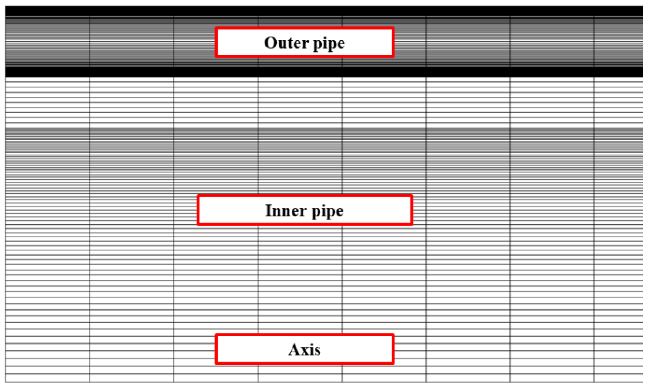
ANSYS Fluent®, a commercial software package, was used to create the geometry for the simulations, form a structured grid, and perform the simulations. The grid geometry is shown in Figure 2. The total number of elements in the reference case was 36,000, with 70 radial divisions within the inner pipe, 10 in the solid zone that is between the inner and outer pipe, 100 in the outer pipe, and 200 in the axial direction.
The grid dependency test of the simulations was conducted by changing the number of elements from those listed above by the ratios 50%, 100%, and 200% and using the outlet mole fractions from the inner pipe and the outlet liquid mass flow rate from the outer pipe as comparison criteria. From the simulations with different grid sizes, the differences are <0.1% for the inner pipe and <1.27% for the outer pipe. Thus, this relatively insignificant grid dependence confirms that the simulation conditions are reasonable.
For this research, the finite volume method was selected to solve the partial differential equations that describe the operation of the MSR. For spatial discretization, PRESTO! was selected for the pressure, a first-order upwind scheme for the volume fraction, and a second-order upwind scheme for the rest. The species transport model was used to simulate the chemical reactions and assumed a volumetric reaction to simplify the analysis. The Eulerian model for the condensation phenomenon of the two-fluid model represents void fractions of the phases and the Ranz–Marshall model to compute the heat transfer coefficient. The convergence criterion was set as all residuals dropping to less than 10−6.

2.2. Governing Equations of the Methanol–Steam-Reforming Reactions with Phase Change Heat Transfer

Since the double-pipe reactor comprises both an inner pipe and an outer pipe, there are two fluid domains. The governing equations in each domain must be set up to satisfy the analysis conditions. Inside the inner pipe, the single-phase gas flow was assumed. The governing equations for this single-phase flow are as follows:
Mass conservation equation:
( γ ρ ) t + · ( γ ρ v ) = 0 ,
Momentum conservation equation:
t ( γ ρ v ) + · ( γ ρ v v ) = γ p + · ( γ τ = ) + γ B f ( μ α + C 2 ρ α | v | ) v ,
Energy conservation equation:
t ( γ ρ f E f + ( 1 γ ) ρ s E s ) + · ( v ( ρ f E f + p ) ) = · [ k e f f T ( i h i J i ) + ( τ = · v ) ] + S f h
The methanol–steam-reforming reactions comprise a steam-reforming (SR) reaction, a water–gas shift (WGS) reaction, and a methanol decomposition (MD) reaction. These chemical reactions are as follows:
SR reaction:
C H 3 O H + H 2 O C O 2 + 3 H 2 ,
WGS reaction:
C O + H 2 O C O 2 + H 2 ,
MD reaction:
C H 3 O H C O + 2 H 2 .
The dominant reaction is the SR reaction, which is endothermic. A heat supply is thus required to activate this endothermic methanol–steam-reforming reaction. The relevant conservation equations are as follows:
Species transport conservation equation:
t ( ρ Y i ) + · ( ρ v Y i ) = · J i + R i + S i ,
Mass diffusivity equation in laminar flow:
J i = ρ D i , m Y i D T , i T T .
The Arrhenius equation is required to calculate the reaction rate, which is as follows.
Molar rate of creation/destruction:
R ^ i , r = Γ ( v i , r v i , r ) ( k f , r j = 1 N [ C j , r ] η j , r k b , r j = 1 N [ C j , r ] η j , r ) ,
Arrhenius equation:
k = k 0 exp ( E a R T ) ,
where k 0 and E a are the pre-exponential factor and activation energy, respectively. They have different values, depending on the type of catalyst and the specific reaction, and they are obtained through experimental validation and numerical analysis. The kinetic constants used in the simulation model are for the RP-60 catalyst [10]. Pepply et al. [24] derived the following Langmuir–Hinshelwood rate expressions for each of the three overall methanol–steam-reforming reactions through the kinetic analysis and from the elementary reactions:
SR reaction:
r S R = k S R K C H 3 O ( 1 ) * P C H 3 O H P H 2 1 2 ( 1     P H 2 3 P C O 2 k S R P H 2 O P C H 3 O H ) C S 1 T C S 1 a T S a ( 1 + K C H 3 O ( 1 ) * P C H 3 O H P H 2 1 2 + K O H ( 1 ) * P H 2 O P H 2 1 2 + K H C O O ( 1 ) * P H 2 1 2 P C O 2 ) ( 1 + K H ( 1 a ) * P H 2 ) ,
WGS reaction:
r W G S = k W G S K O H ( 1 ) * ( P C O P H 2 O P H 2 1 2 ) ( 1 P H 2 P C O 2 k W G S P C O P H 2 O ) C S 1 T 2 S a ( 1 + K C H 3 O ( 1 ) * P C H 3 O H P H 2 1 2 + K H C O O ( 1 ) * P H 2 1 2 P C O 2 + K O H ( 1 ) * P H 2 O P H 2 1 2 ) 2 ,
MD reaction:
r M D = k M D K C H 3 O ( 2 ) * P C H 3 O H P H 2 1 2 ( 1 P H 2 3 P C O 2 k M D P C H 3 O H ) C S 2 T C S 2 a T S a ( 1 + K C H 3 O ( 2 ) * P C H 3 O H P H 2 1 2 + K O H ( 2 ) * P H 2 O P H 2 1 2 ) ( 1 + K H ( 2 a ) * P H 2 ) .
Since catalyst–surface mechanisms promote the methanol–steam-reforming reactions, the mole concentrations and the surface area of the catalyst crucially affect the basic reactions, as shown by the form of the Langmuir–Hinshelwood rate expressions [25]. Thus, to apply the experimentally validated kinetic constants, they were adjusted to take into account the mole concentrations, surface area, and density of the catalyst [10,24,25,26,27]. The adjusted kinetic constants for the overall reactions are listed in Table 2.
Superheated steam is supplied inside the outer pipe so that the latent heat of the superheated steam is transferred into the inner pipe. Consequently, as some portion of the superheated steam condenses, a two-phase flow should be considered to solve the governing equations in this fluid domain. To simulate the behavior of the two phases, taking into account both the effectiveness of heat transfer through the interface between the inner and outer pipes and the phase change energy is necessary. The governing equations are as follows:
Mass conservation equation:
t ( α q ρ q ) + · ( α q ρ q v q ) = p = 1 n ( m ˙ p q m ˙ q p ) + S q ,
Momentum conservation equation:
t ( α q ρ q v q ) + · ( α q ρ q v q v q ) = α q p + · τ = q + α q ρ q g + p = 1 n ( R p q + m ˙ p q v p q m ˙ q p v q p ) ,  
Energy conservation equation:
t ( α q ρ q h q ) + · ( α q ρ q v q h q ) = α q d p q d t + τ = q · v q q q + S q + p = 1 n ( Q p q + m ˙ p q h p q m ˙ q p h q p )
The condensation phenomenon is expressed using the Lee model of ANSYS Fluent®, and the relevant transport equations are as follows:
Vapor transport equation:
t ( α v ρ v ) + · ( α v ρ v v v ) = m ˙ v l ,
Mass transport (condensation):
m ˙ v l = c o e f f · α v ρ v ( T s a t T v ) T s a t .
The only mass transport that occurs in the MSR studied here is the condensation phenomenon. Therefore, the right-hand side of Equation (17) is expressed as a negative value. In Equation (18), coeff is an adjustable parameter that varies the rate of the mass transport. The mass transport rate is determined by comparing Equation (18) with the actual value.

2.3. Validation of the Two-Phase Flow Model

Due to the difficulty of high-pressure steam experiments, the two-phase model was validated indirectly using SPACE code, which takes into account evaporation and condensation in a very-high-pressure steam generator. It is a programming language based on C/C++. The SPACE code was developed by Korean national nuclear research institutes and industries and provides high-fidelity simulations of the behavior of high-pressure steam [28]. It is a safety analysis code that considers two-phase flow phenomena to predict the thermal–hydraulic analysis of pressurized water nuclear reactors, and it has been validated through numerous experiments.
The SPACE code was used to validate the two-phase flow simulation of the MSR. The coeff in Equation (18) is then used as a parameter to adjust the simulated mass transfer to agree with the results from the SPACE code. Before validation, the SPACE code sets up the same geometry as the double-pipe MSR. That is, the inner wall of the inner pipe was set to a constant temperature (553.467 K). This was the calculated value after c o e f f was set to 50. Using the results of the SPACE code, we applied the selected value of c o e f f to the conjugate heat transfer simulation and compared the results. The control volume is the entire region, except for the inside of the inner pipe, and the other conditions—except for the wall temperature—are the same as those of the conjugate heat transfer MSR.
The equations used to calculate the interphase drag, frictional pressure gradient [29], and heat transfer coefficient in the two-phase flow [30] are as follows:
Interphase drag:
F i = 1 2 ρ v f i | v v u l | ( v v u l ) ,
Frictional pressure gradient:
d p d x = 1 α l 2 2 f l | α l u l | ( α l u l ) D h ρ l ,
Heat-transfer coefficient:
h = h s f ( 1 + 3.8 Z 0.95 ) .
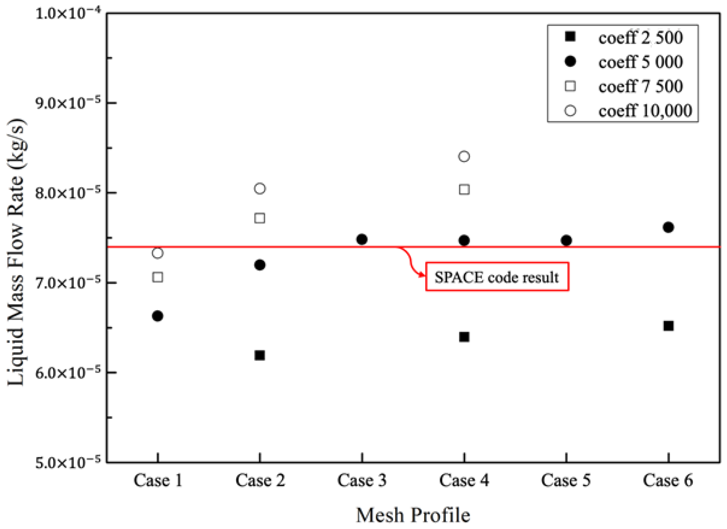
The grid dependency test was conducted with the six grid scenarios (cases) shown in Table 3, with various c o e f f selections; the simulation results are summarized in Figure 3. The values of c o e f f were considered to range from 2500 to 10,000. As for the conjugate heat transfer simulation, the grids were divided into the radial and axial directions.
The comparison criterion was the liquid mass flow rate at the outlet of the outer pipe, for which the result from the SPACE code was approximately 7.413 × 10⁻⁵ kg/s. The smallest differences between our simulations and the SPACE code results were obtained with a   c o e f f of 5000; they were 0.911%, 0.773%, and 0.750%, respectively, for Cases 3, 4, and 5. Therefore, the selected geometry of the grid was Case 4 and the c o e f f value was 5000 to reduce the simulation time and improve the accuracy.

3. Results and Discussion

3.1. Performance of the Methanol–Steam-Reforming Reactions Using Two Different Types of Heat Sources

As the methanol–steam-reforming reactor comprises a double pipe, the temperature of the reforming side must decrease in the longitudinal direction, owing to the growth of the endothermic reaction. This decrease in the temperature profile results in a reduction in the methanol conversion. In this study, sensible heat or latent heat was used to supply the heat to the methanol-reforming reactions. Sensible heat is provided by high-temperature air, while the latent heat transfer is provided by the phase change of high-pressure steam. The specific heat of high-pressure steam at 6550 kPa and 558.76 K is 4748.3   J / kg · K , while the specific heat of air under the same conditions is 1073.9   J / kg · K . This information enables us to determine the mass flow rate for each heat source so that the mass flow rate into the outer pipe provides the same thermal energy supply. The thermal energy from the heat source is then calculated as follows:
Q = C p · m ˙ · T .
Due to the large difference in the specific heats, the air flow rate must be higher than the steam flow rate. Since the thermal energy of the steam is approximately 6000 W, the mass flow rate of air for the same heat capacity is approximately 10 4   kg / s .
Figure 4 shows the temperature contours of the methanol–steam-reforming reactions for the two different heat sources. As descripted, Figure 4a,b show both the inner pipe and outer pipe, and Figure 4c,d show only the outer pipe. The radial scale in Figure 4a,b is enlarged by a factor of 10 (i.e., the aspect ratio is 1:10). At the interface between the inner and outer pipes, endothermic heat absorption reduces the temperature of the reactant. The temperature of the outer pipe shows a different trend. In Figure 4a, when steam flows through the outer pipe, the steam temperature is maintained. Since the heat flux into the inner pipe is then maintained along the longitudinal direction of the pipe, the methanol–steam-reforming reactions progress along the pipe.
However, the heat transfer from the air flow to the methanol-reforming reactions reduces the temperature of the air along the pipe, which decreases the activation of the reforming reactions along the pipe. Figure 4b also shows that the temperature gradient in the radial direction of the heat source zone dramatically decreases. This reduction of the temperature gradient reduces heat transfer into the methanol-reforming zone in the inner pipe.
The core of the cold zone in the methanol-reforming region also varies with the type of heat source. Since the methanol–steam-reforming reactions absorb sufficient thermal energy from the latent heat of the steam, the activated endothermal reaction lowers the temperature of the methanol–steam-reforming reaction zone. The lowest temperature is then observed to be 482.42 K in the methanol–steam-reforming reactor that utilizes the latent heat of the steam.
The core of the cold zone is defined to be the center of the temperature contour that has the lowest temperature throughout. In Figure 4, the location of the core of the cold zone also varies with the heat source. As more heat is absorbed from the latent heat of the steam close to the entrance of the inner pipe, the location of the cold zone core also occurs closer to that entrance (i.e., is advanced) in this case. Conversely, as the heat transfer from the air flow is retarded in comparison with the case in which the latent heat is utilized, owing to the reduction of the heat flux in the radial direction, the cold zone core with an air flow is also retarded.
Figure 4c,d compare the temperatures in the outer pipe in more detail. These figures have been enlarged by a factor of 50 (aspect ratio 1:50) in the radial direction. The lowest temperature, which was 524.202 K, occurred when the air was used as the heat source. This is much lower than the lowest temperature of 553.468 K in the MSR when the latent heat of water vapor was used.
The heat source supplied from the right side of the MSR in Figure 4d shows that the temperature of the air decreases as the heat exchange with the inner pipe progresses, and the temperature of the wall decreases the most in the inlet area of the inner pipe, where the chemical reactions occur actively. However, the temperature of the wall at the outlet of the outer pipe increases again. The reason for this is that the temperature of the air is significantly decreased by the chemical reactions in the inner pipe, which, in turn, takes heat away from the inlet of the inner pipe. This means that it does not serve as a heat source under these conditions.
However, Figure 4c reveals that the temperature of the steam is maintained without reduction. When the phase change energy of the steam is utilized, the temperature difference is ~5.29 K, which is much lower than the 34.56 K temperature difference obtained when using air. Therefore, when the phase change energy is used, it is possible to supply heat with only a minimal temperature drop.
The longitudinal temperature profile shows that heat absorption by the endothermic reactions affects the temperature profile of the steam less than that of air. Figure 5 shows the difference in the temperature profile through the outer/inner pipe for the two different heat sources. Latent-I is the inner wall temperature of the inner pipe, while Latent-O is the inner wall temperature of the outer pipe. The same rule applies to Sensible-I and Sensible-O. A significant temperature drop is observed when the sensible heat source is used for the methanol–steam-reforming reactions. By contrast, the wall temperature changes only gradually along the pipe when the latent heat source is used. We adopted the standard deviation of the inner wall temperature of the inner pipe to compare the temperature uniformity. The standard deviation indicates how large the differences are from the average value, and it was used to compare measurements of the temperature uniformity. With latent heat, the standard deviation was ~0.81 K, but with sensible heat, it was ~7.15 K. Considering that the corresponding average temperatures of the inner wall were 553.30 and 532.37 K, respectively, if we use latent heat as the heat source, then heat can be supplied to the inner pipe at a more uniform, as well as higher, temperature.
When phase change energy was used, the heat flux increased steadily as the heat source entered the inlet. As shown in Figure 5a, the reduction in the wall temperature when only sensible heat is used implies that the heat transfer from the outer pipe is weak. Figure 5b shows the surface heat flux through the inner wall of the inner pipe. The heat flux was relatively uniform when sensible heat was used, and it decreased rapidly within 0.1 m from the outlet of the outer pipe. As mentioned, the decreasing wall temperature reduced the activation of the methanol-reforming reaction, so a relatively uniform heat flux was maintained. However, when latent heat was provided, the inner wall temperature of the outer pipe decreased gradually. This gradual reduction of the temperature sustains the endothermic reactions so that they remain more activated along the length of the pipe.
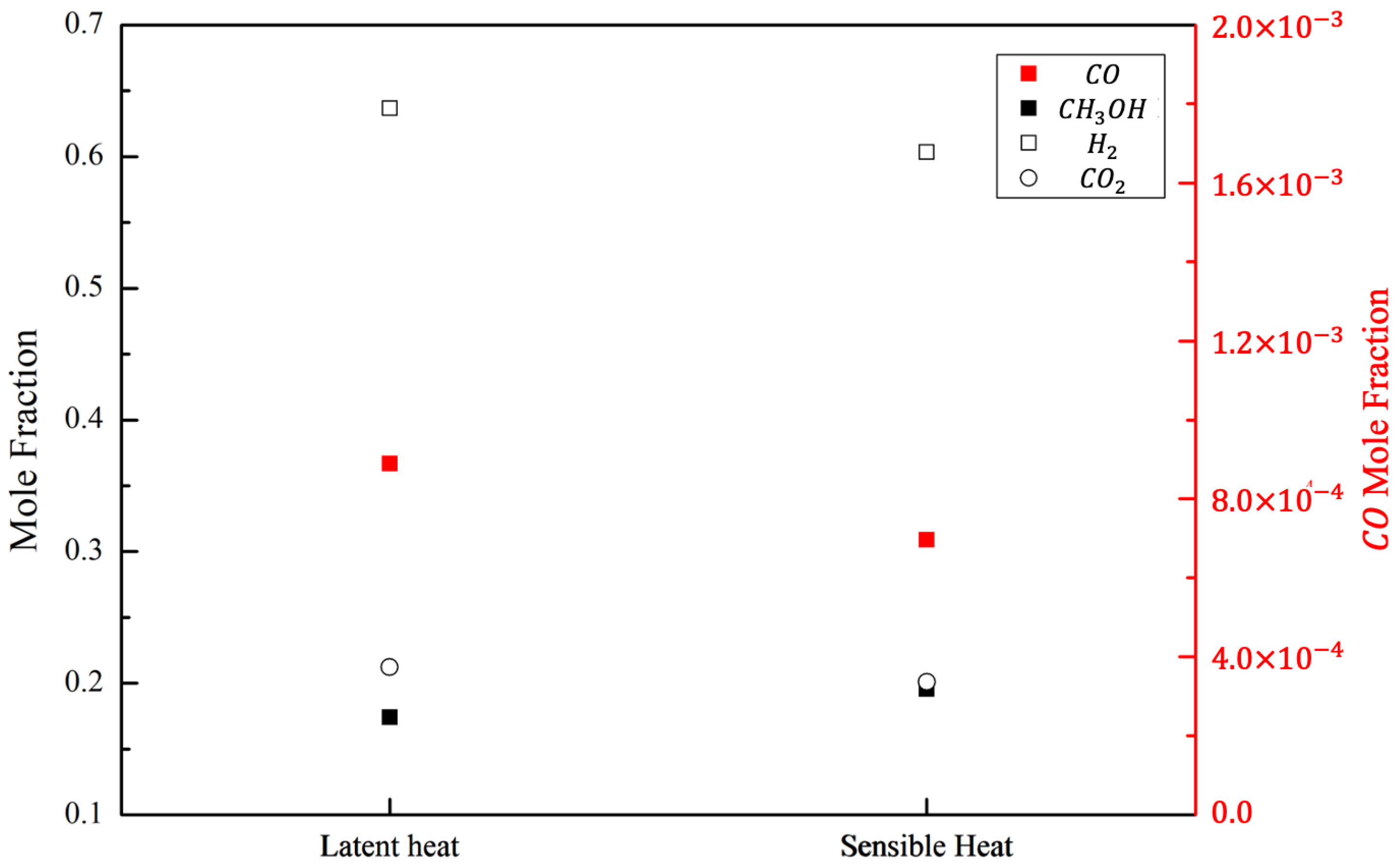
The mole fraction of product species from the methanol-reforming reactions is shown in Figure 6. All product species are on a dry basis. As expected, the hydrogen fraction was a higher methanol-reforming product when the latent heat source was used. Since more C O was produced with a higher conversion of methanol, a higher fraction of C O was also observed as a methanol-reforming product with the latent heat source.

3.2. SA of the Methanol–Steam-Reforming Reactions with a Latent-Heat Source

As shown in the previous section, the methanol–steam-reforming reactions were enhanced with a latent heat source. As latent heat was supplied to the methanol-reforming reactions, they were sustained steadily along the annular pipe, with only a small temperature drop. Accordingly, the methanol–steam-reforming reactions that utilized latent heat were expected to be dominated by different parameters compared to those with a typical convective heat source. Therefore, the dominant parameters for methanol conversion were investigated.

3.2.1. Parameter Descriptions

Comparison of the two different heat sources showed that the methanol-reforming reactions proceeded more uniformly along the reactor pipe when latent heat was provided. In this study, a parametric investigation was conducted to analyze the sensitivity of the methanol conversion rate variations. The SA of various thermal–fluid parameters was used to understand the performance variations of the MSR. The variables were SCR, GHSV-I and O, Temp.-I and O, reactor length, and Pressure-I. The methanol conversion rate and hydrogen yield on a dry basis are measurable variables that can be used to evaluate the sensitivity of the MSR performance. The degree of variation is as follows:
Degree of variation:
D e g r e e   o f   v a r i a t i o n   o f   X   [ % ] = ϕ n e w ϕ r e f ϕ r e f × 100 ,
where X is the percentage change in the parameter ϕ for a change in the methanol conversion rate. In each computational study, only one parameter is changed, while the other parameters are held constant.

3.2.2. Sensitivity of the Reformer Performance to Various Parameters

In each simulation, the methanol conversion rate varies significantly with the changes in some parameters, while other parameters produce only small variations in the methanol conversion rate. In particular, variations in GHSV-I, SCR, and Pressure-I change the methanol conversion rate remarkably. However, the temperature of the inner wall of the outer pipe has less effect on the methanol conversion rate owing to latent heat transfer. Figure 7 shows the percentage variation of the methanol conversion rate according to the changes in various parameters.
As the amount of steam was increased, the SCR increased. When the steam flow rate increased, the total mass flow and enthalpy of the methanol–steam mixture increased. Thus, the higher methanol conversion rate was due to the increased amounts of both reactants and thermal energy. However, as the amount of steam increased, the rate of increase of the methanol conversion decreased. This occurred because the inflow rate increased owing to the increased steam supply, which resulted in insufficient methanol–steam-reforming reactions in the given reactor.
Since this simulation study was conducted for a double pipe, the GHSV of the inner flow was controlled manually by the flow rate. However, the steam flow through the outer pipe was also controlled by the flow rate. For convenience, we labeled the simulated flow variation through the inner pipe as GHSV-I and the flow variation through the outer pipe as GHSV-O. An increase in GHSV-I significantly reduced the methanol conversion rates owing to the reduced retention time of the reactants in the reactor. However, the hydrogen mass flow rate at the outlet increased by 48.02% and 35.19% for GHSV-I. The increase in GHSV-I thus increased the hydrogen yield, but it also increased the amount of unreacted gas, which resulted in a significant reduction in the methanol conversion rate. By contrast, varying the GHSV-O made no significant difference. When the phase change energy of steam was used, the wall temperature of the outer pipe was kept almost constant by the condensation phenomenon, which thus increased the heat supply only slightly owing to latent heat transfer from the outer pipe. The increase in GHSV-O affected the liquid mass flow rate through the outer pipe more than it affected the methanol conversion rate.
Similarly, the inlet temperatures of the inner and outer pipes were separated. Temp.-I was the temperature of the reactant; the increase in the methanol conversion rate with an increasing reactant temperature occurred over a small range of 4%. However, Temp.-I produced the largest percentage change compared with the other variables, because the methanol–steam-reforming reaction was most affected by the temperature. Although the methanol conversion rate was increased by increasing Temp.-I, the average heat flux and liquid mass flow rate through the outer pipe were reduced, owing to the reduced heat transfer. By contrast, Temp.-O had little effect on the methanol conversion rate because of the phase change energy. An increase in Temp.-O had the effect of increasing the heat supply and decreasing the liquid mass flow rate by keeping the condensation point away from the inlet of the outer pipe.
An increase in the length of the reactor had the effect of increasing the amount of catalyst required and the dwell time in the reactor. Thus, the methanol–steam-reforming reactions occurred over a longer duration, and the methanol conversion rate increased. In addition, owing to the heat supply, the outlet temperature of the inner pipe increased from 518.08 to 541.85 K, and the liquid mass flow rate through the outer pipe increased by about two times. In the case of a 1.4-m-long 1.0 ϕ G H S V reactor, which had the same GHSV as a 0.7-m-long 0.5 ϕ G H S V reactor, the methanol conversion rate increased by ~0.06% as the heat exchange with the outer pipe increased. If the length of the reactor is increased by four times, the methanol conversion rate increases by about two times. This is because the methanol–steam-reforming reactions are most active at the beginning of the reactor, and the reaction rates do not increase linearly with the reactor length.
The mass flow rate through the inner pipe was kept constant for comparison when the operating pressure of the reactor was varied. The inflow velocity decreased from 1.38 to 0.016 m/s, because the density of the reactant increased as the pressure increased. For the same mass flow rate, an increase in the operating pressure increased the methanol conversion rate significantly, but the rate of the increase decreased.
For the abovementioned reasons, the change in hydrogen yield was the same as that of the methanol conversion rate, as seen in Table 4.

4. Conclusions

In this study, the thermal–fluid parameters of a double-pipe MSR using two types of heat sources were compared and analyzed. The conclusions are as follows:
  • An MSR that utilizes the phase change energy of steam can supply thermal energy at a uniform and higher temperature than an MSR that employs only the sensible heat of a gas. Moreover, it has a better performance in terms of hydrogen production.
  • The thermal–fluid parameters of the reactor are more affected by the change in the boundary conditions of the inner pipe, where the methanol–steam-reforming reactions occur. This is because the wall temperature remains almost uniform owing to the phase change energy supplied by the water vapor.
  • Increasing the temperature and velocity through the outer pipe can increase the heat transfer to the inner pipe and reduce the liquid mass flow rate. However, the temperature of the wall is kept almost uniform, so it does not have a significant effect on the methanol–steam-reforming reaction.

Author Contributions

Conceptualization, H.J. and S.Y.; methodology, B.K. and H.J.; software, D.Y. and B.K.; validation, D.Y.; formal analysis, B.K.; investigation, D.Y., B.K. and S.Y.; resources, H.J.; data curation, D.Y. and S.Y.; writing—original draft preparation, D.Y.; writing—review and editing, D.Y. and S.Y.; visualization, D.Y. and B.K.; supervision, S.Y.; project administration, S.Y.; funding acquisition, H.J. All authors have read and agreed to the published version of the manuscript.

Funding

This research was supported by a grant from the Agency for Defense Development (ADD) (grant number: UD180051GD, Level of contribution: 75%) and the National Research Foundation of Korea (NRF) grant funded by the Korea government. (Ministry of Science, ICT & Future Planning) (No. 2019R1A2C1087784, Level of contribution: 25%).

Informed Consent Statement

Not applicable.

Data Availability Statement

Not applicable.

Conflicts of Interest

The authors declare no conflict of interest.

Abbreviations

Definitions of Symbols
BDimensionless permeability
CConcentration
C 2 Pressure jump coefficient
DhHydraulic diameter
Di,mMass diffusion coefficient
DT,iThermal diffusion coefficient
ETotal energy
EaActivation energy
F External force
fiFriction coefficient
flFanning friction factor
hEnthalpy
hsfSuperficial heat transfer coefficient
IInner pipe
JMass diffusivity
J i Diffusion flux of species
KiAdsorption equilibrium coefficient for i
k0Pre-exponential factor
kb,rBackward rate constant
k e f f Effective thermal conductivity
kf,rForward rate constant
m ˙ Mass flow rate
OOuter pipe
PPressure
RIdeal gas constant
RiNet rate of production
R p q Interaction force between phases
R ^ i , r Arrhenius molar rate of creation/destruction of species i in reaction r
SiRate of creation source term
S f h Fluid enthalpy source term
TTemperature
tTime
v Velocity vector
v i , r Stoichiometric coefficient for reactant i in reaction r
v i , r Stoichiometric coefficient for product i in reaction r
YiLocal mass fraction
ZFunction of thermodynamic vapor gravity and pressure
Greek Letters
α Void fraction
γ Porosity
η j , r Rate exponent for reactant species j in reaction r
η j , r Rate exponent for product species j in reaction r
ρ Density
τ = Stress tensor
Subscripts
fFluid
i, jSpecies
lLiquid
p, qPhases
sSolid
satSaturation
vVapor

References

  1. De-Troya, J.J.; Alvarez, C.; Fernández-Garrido, C.; Carral, L. Analysing the possibilities of using fuel cells in ships. Int. J. Hydrogen Energy 2016, 41, 2853–2866. [Google Scholar] [CrossRef]
  2. Psoma, A.; Gunter, S. Fuel cell systems for submarines: From the first idea to serial production. J. Power Sources 2002, 106, 381–383. [Google Scholar] [CrossRef]
  3. Krummrich, S.; Javier, L. Methanol reformer–The next milestone for fuel cell powered submarines. Int. J. Hydrog. Energy 2015, 40, 5482–5486. [Google Scholar] [CrossRef]
  4. Sa, S.; Jose, M.S.; Adelio, M. Steam reforming of methanol over a CuO/ZnO/Al2O3 catalyst, part I: Kinetic modelling. Chem. Eng. Sci. 2011, 66, 4913–4921. [Google Scholar] [CrossRef]
  5. Palo, D.R.; Robert, A.D.; Jamie, D.H. Methanol steam reforming for hydrogen production. Chem. Rev. 2007, 107, 3992–4021. [Google Scholar] [CrossRef]
  6. Garcia, G.; Arriola, E.; Chen, W.H.; De Luna, M.D. A comprehensive review of hydrogen production from methanol thermochemical conversion for sustainability. Energy 2020, 217, 119384. [Google Scholar] [CrossRef]
  7. Chen, W.-H.; Bo-Jhih, L. Effect of microwave double absorption on hydrogen generation from methanol steam reforming. Int. J. Hydrog. Energy 2010, 35, 1987–1997. [Google Scholar] [CrossRef]
  8. Conant, T.; Karim, A.M.; Lebarbier, V.; Wang, Y.; Girgsdies, F.; Schlögl, R.; Datye, A. Stability of bimetallic Pd–Zn catalysts for the steam reforming of methanol. J. Catal. 2008, 257, 64–70. [Google Scholar] [CrossRef]
  9. Chein, R.; Yen-Cho, C.; Chung, J.N. Axial heat conduction and heat supply effects on methanol-steam reforming performance in micro-scale reformers. Int. J. Heat Mass Transf. 2012, 55, 3029–3042. [Google Scholar] [CrossRef]
  10. Ribeirinha, P.; Abdollahzadeh, M.; Boaventura, M.; Mendes, A. H2 production with low carbon content via MSR in packed bed membrane reactors for high-temperature polymeric electrolyte membrane fuel cell. Appl. Energy 2017, 188, 409–419. [Google Scholar] [CrossRef]
  11. Faungnawakij, K.; Ryuji, K.; Koichi, E. Thermodynamic evaluation of methanol steam reforming for hydrogen production. J. Power Sources 2006, 161, 87–94. [Google Scholar] [CrossRef]
  12. Yun, J.; Ngoc, V.T.; Sangseok, Y. Performance improvement of methanol steam reforming system with auxiliary heat recovery units. Int. J. Hydrogen Energy 2021, 46, 25284–25293. [Google Scholar] [CrossRef]
  13. Mao, X.; Li, W.; Yuan, Y.; Yang, L. Numerical analysis of methanol steam reforming reactor heated by catalytic combustion for hydrogen production. Int. J. Hydrogen Energy 2022, 47, 14469–14482. [Google Scholar] [CrossRef]
  14. Srivastava, A.; Parmod, K.; Atul, D. Performance enhancement of methanol reforming reactor through finned surfaces and diffused entry for on-board hydrogen generation. Int. J. Hydrogen Energy 2022, 47, 7478–7490. [Google Scholar] [CrossRef]
  15. Saltelli, A. Sensitivity analysis for importance assessment. Risk Anal. 2002, 22, 579–590. [Google Scholar] [CrossRef] [PubMed]
  16. Shin, G.; Jinwon, Y.; Sangseok, Y. Thermal design of methane steam reformer with low-temperature non-reactive heat source for high efficiency engine-hybrid stationary fuel cell system. Int. J. Hydrogen Energy 2017, 42, 1469–14707. [Google Scholar] [CrossRef]
  17. Yun, J.; Sangseok, Y. Transient behavior of 5 kW class shell-and-tube methane steam reformer with intermediate temperature heat source. Int. J. Heat Mass Transf. 2019, 134, 600–609. [Google Scholar] [CrossRef]
  18. Shi, X.; Che, D.; Agnew, B.; Gao, J. An investigation of the performance of compact heat exchanger for latent heat recovery from exhaust flue gases. Int. J. Heat Mass Transf. 2011, 54, 606–615. [Google Scholar] [CrossRef]
  19. Osakabe, M.; Ishida, K.; Yagi, K.; Itoh, T.; Ohmasa, K. Condensation heat transfer on tubes in actual flue gas. Heat Transf. Asian Res. Co-Spons. By Soc. Chem. Eng. Jpn. Heat Transf. Div. ASME 2001, 30, 139–151. [Google Scholar] [CrossRef]
  20. White, M.T.; Abdulnaser, I.S. A new method to identify the optimal temperature of latent-heat thermal-energy storage systems for power generation from waste heat. Int. J. Heat Mass Transf. 2020, 149, 119111. [Google Scholar] [CrossRef]
  21. Ji, H.; Lee, J.; Choi, E.; Seo, I. Hydrogen production from steam reforming using an indirect heating method. Int. J. Hydrogen Energy 2018, 43, 3655–3663. [Google Scholar] [CrossRef]
  22. Song, H.; Kim, Y.; Yu, D.; Kim, B.J.; Ji, H.; Yu, S. A computational analysis of a methanol steam reformer using phase change heat transfer. Energies 2020, 13, 4324. [Google Scholar] [CrossRef]
  23. Yu, D.; Kim, B.; Van Trinh, N.; Ji, H.; Yu, S. Analysis of phase change heat transfer with annulus 1 kW class methanol steam reforming reaction under high-pressure operation. Int. J. Hydrogen Energy 2021, 46, 28775–28788. [Google Scholar] [CrossRef]
  24. Peppley, B.A.; Amphlett, J.C.; Kearns, L.M.; Mann, R.F. Methanol–steam reforming on Cu/ZnO/Al2O3 catalysts. Part 2. A comprehensive kinetic model. Appl. Catal. A Gen. 1999, 179, 31–49. [Google Scholar] [CrossRef]
  25. Peppley, B.A. A Comprehensive Kinetic Model of Methanol-Steam Reforming on Cu/ZnO/Al2O3 Catalyst. Ph.D. Thesis, The Royal Military College of Canada, Kingston, ON, Canada, 1998. [Google Scholar]
  26. Frilund, C. CO2 Hydrogenation to Methanol. Master’s Thesis, Aalto University, Espoo, Finland, 2016. Appendix2 (2/2). Available online: https://aaltodoc.aalto.fi/bitstream/handle/123456789/19938/master_Frilund_Christian_2016.pdf?sequence=1 (accessed on 31 January 2016).
  27. Chiu, Y.J.; Chiu, H.C.; Hsieh, R.H.; Jang, J.H.; Jiang, B.Y. Simulations of hydrogen production by methanol steam reforming. Energy Procedia 2019, 156, 38–42. [Google Scholar] [CrossRef]
  28. Ha, S.J.; Park, C.E.; Kim, K.D.; Ban, C.H. Development of the SPACE code for nuclear power plants. Nucl. Eng. Technol. 2011, 43, 45–62. [Google Scholar] [CrossRef] [Green Version]
  29. Wallis, G.B. One-Dimensional Two-Phase Flow McGraw-Hill Book Company; McGraw Hill Book Company: New York, NY, USA, 1969. [Google Scholar] [CrossRef]
  30. Saha, P.; Novak, Z. Point of net vapor generation and vapor void fraction in subcooled boiling. In Proceedings of the International Heat Transfer Conference Digital Library, Tokyo, Japan, 3–7 September 1974. [Google Scholar]
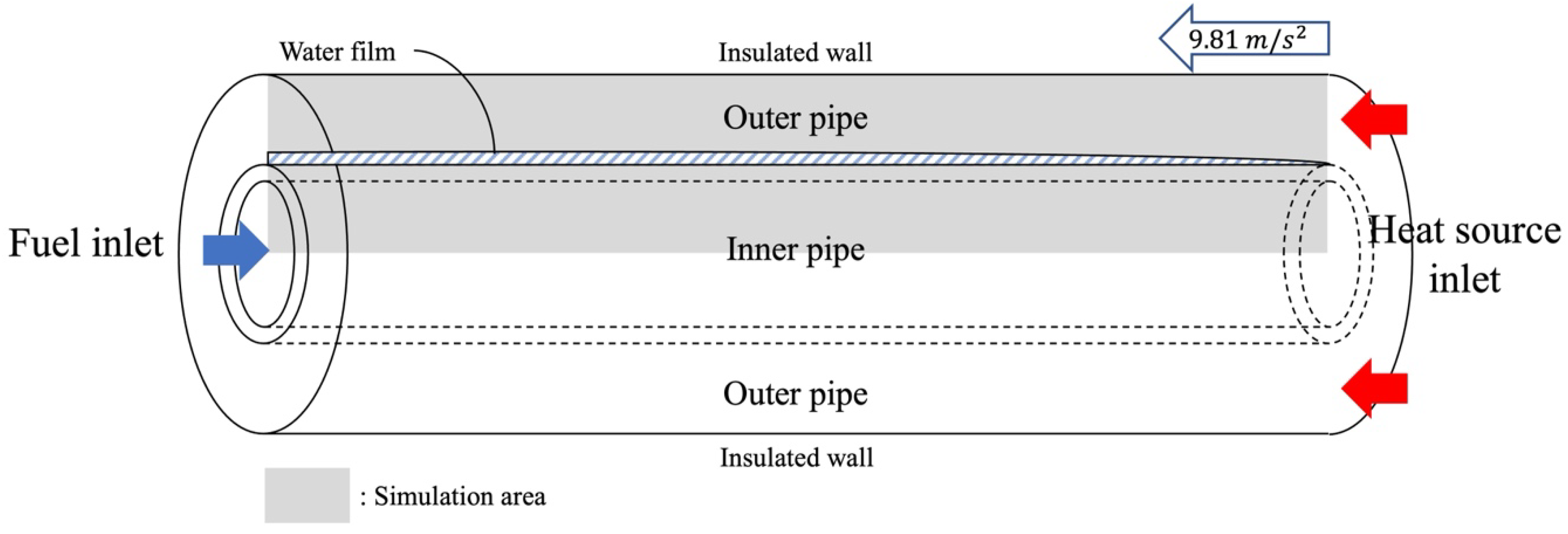
Figure 1. Schematic diagram of the annular methanol–steam reformer (MSR).
Energies 15 03832 g001
Figure 2. Mesh description.
Energies 15 03832 g002
Figure 3. Results of the validation with the SPACE code.
Energies 15 03832 g003
Figure 4. Temperature contours of the MSR (aspect ratio 1:10) using (a) steam and (b) air and of the outer pipe (aspect ratio 1:50) using (c) steam and (d) air. The color bar below each panel shows the temperature scale.
Energies 15 03832 g004
Figure 5. Trends of wall temperature and surface heat flux for the MSR. (a) Wall temperature profile. (b) Surface heat flux.
Energies 15 03832 g005aEnergies 15 03832 g005b
Figure 6. Outlet mole fractions on a dry basis according to the type of heat source.
Energies 15 03832 g006
Figure 7. Sensitivity analysis of the methanol–steam-reforming reactions.
Energies 15 03832 g007
Table 1. Detailed parameters of the simulation.
ParameterValue
I-inner diameter21.18 mm
I-outer diameter25.4 mm
O-inner diameter31.29 mm
Length700 mm
I-velocity0.417 m/s
O-velocity0.26 m/s
I-temperature543.15 K
O-temperature558.76 K
I-pressure2980 kPa
O-pressure6550 kPa
I-SCR1.2
Table 2. Kinetic constants for the overall methanol–steam-reforming reactions.
Rate Constants k 0 / ( kgmol / m 3 s ) E a / ( J / kmol )
r S R 1.27 × 10 9 92.7 × 10 7
r W G S 3.25 × 10 7 8.77 × 10 7
r M D 9.085 × 10 8 1.22 × 10 8
Table 3. Mesh cases for model validation with the SPACE code.
DivisionCase 1Case 2Case 3Case 4Case 5Case 6
Radial50100200200200400
Axis200200100200300200
Table 4. Hydrogen mole fraction for various parameter changes.
VariableValue H 2 Yields Parameter Change (%) H 2 Yields   Change   ( % )
SCR1.00.610−16.67−1.54
1.20.6190.000.00
1.50.62825.001.37
2.00.63466.672.44
2.50.637108.332.78
GHSV-I 0.5 ϕ G H S V I 0.690−50.0010.89
1.0 ϕ G H S V I 0.6220.000.00
2.0 ϕ G H S V I 0.527100.00−15.33
GHSV-O 0.5 ϕ G H S V O 0.622−50.000.00
1.0 ϕ G H S V O 0.6220.000.00
2.0 ϕ G H S V O 0.622100.000.00
Temp.-I523.15 K0.615−3.68−1.24
533.15 K0.618−1.84−0.61
543.15 K0.6220.000.00
553.15 K0.6261.840.58
558.76 K0.6282.870.89
Temp.-O558.76 K0.6220.000.00
568.76 K0.6221.790.04
578.76 K0.6233.580.18
Length0.35 m0.527−50.00−15.34
0.7 m0.6220.000.00
1.4 m0.690100.0010.91
Pressure-I1 bara0.017−96.64−97.32
15 bara0.485−49.66−22.01
29.8 bara0.6220.000.00
45 bara0.67951.019.05
65.5 bara0.723119.8016.22
Publisher’s Note: MDPI stays neutral with regard to jurisdictional claims in published maps and institutional affiliations.