Article

Modeling and Fuzzy FOPID Controller Tuned by PSO for Pneumatic Positioning System

by
Mohamed Naji Muftah
1,2,
Ahmad Athif Mohd Faudzi
1,3,
Shafishuhaza Sahlan
1,3 and
Mokhtar Shouran
2,4,*
1
Department of Control and Mechatronics Engineering, Faculty of Electrical Engineering, Universiti Teknologi Malaysia, Johor Bahru 81310, Malaysia
2
Department of Control Engineering, College of Electronics Technology, Bani Walid P.O. Box 38645, Libya
3
Centre for Artificial Intelligence and Robotics (CAIRO), Universiti Teknologi Malaysia, Jalan Sultan Yahya Petra, Kuala Lumpur 54100, Malaysia
4
Wolfson Centre for Magnetics, School of Engineering, Cardiff University, Cardiff CF24 3AA, UK
*
Author to whom correspondence should be addressed.
Energies 2022, 15(10), 3757; https://doi.org/10.3390/en15103757
Submission received: 20 April 2022 / Revised: 13 May 2022 / Accepted: 18 May 2022 / Published: 19 May 2022
(This article belongs to the Section F: Electrical Engineering)

Abstract

:
A pneumatic cylinder system is believed to be extremely nonlinear and sensitive to nonlinearities, which makes it challenging to establish precise position control of the actuator. The current research is aimed at reducing the overshoot in the response of a double-acting pneumatic actuator, namely, the IPA positioning system’s reaction time. The pneumatic system was modeled using an autoregressive with exogenous input (ARX) model structure, and the control strategy was implemented using a fuzzy fractional order proportional integral derivative (fuzzy FOPID) employing the particle swarm optimization (PSO) algorithm. This approach was used to determine the optimal controller parameters. A comparison study has been conducted to prove the advantages of utilizing a PSO fuzzy FOPID controller over PSO fuzzy PID. The controller tuning algorithm was validated and tested using a pneumatic actuator system in both simulation and real environments. From the standpoint of time-domain performance metrics, such as rising time (tr), settling time (ts), and overshoot (OS%), the PSO fuzzy FOPID controller outperforms the PSO Fuzzy PID controller in terms of dynamic performance.

1. Introduction

Pneumatic actuators (PAs) are widely employed in a variety of applications, especially those that require automatic control due to their advantages, which include low cost, a high power-to-weight ratio, and the use of air as an operating medium [1]. However, the air leakage, friction, air compressibility, and uncertainty in the parameters of the pneumatic actuator system make precise position control a challenge [2,3]. Additionally, the modeling of the empirical pneumatic actuator system is considered difficult due to the limitations and complexity of the system.
System identification (SI) is a technique for solving system modeling and unknown parameters, as well as for linearizing the system to overcome the drawbacks of mathematical models [4]. Additionally, system identification can be utilized to derive the plant system’s linear mathematical model (transfer function) from the experimental data. A further significant factor to be addressed is the restrictions or constraints of the system while designing a controller for actual system applications [5,6]. Non-compliance with the system’s limitations could cause system damage and component harm, as well as a decrease in control system performance.
Numerous control mechanisms have been developed to maintain the position of the pneumatic system; for instance, a PI controller was developed in 2010 and used for the first time to control the positioning system of an intelligent pneumatic actuator (IPA) [7,8]. Two years later, another study presented a pole-placement feedback controller for the same task [9]. In 2013, a bang–bang controller and a PI controller were implemented to access the real-time position control of the IPA system [10]. During the last years, researchers have tried to control the position of IPA systems using a predictive controller [11,12,13,14,15,16].
Earlier research did not address the IPA system’s limits such as the control signal to the valve, especially during the actual implementation of control systems. Furthermore, noncompliance with the required limitations may be dangerous to the components of the IPA system and the general performance of the control system. Additionally, the majority of the previously described control systems were unable to achieve high speed response, robustness, and accuracy all at the same time, especially when implemented in real-time scenarios.
In this study, the fuzzy fractional order proportional integral derivative controller (fuzzy FOPID) is proposed. The FOPID provides more design flexibility than traditional PID controllers. In addition, it has a bigger stability region, selectivity, and other benefits. This is due to the acceptance of fraction orders of derivatives and integrals [17,18,19,20,21]. In addition, numerous researchers have adopted FOPID controllers in recent years due to the additional factors that make the system more durable and successful in a variety of applications. Moreover, according to the results of the investigation, numerous systems, such as motor control systems [22], robotics systems [23], and time-delay systems [24] used FOPID as a controller. The performance of the FOPID controller is superior to that of traditional PID controllers in terms of time response characteristics.
In comparison with traditional PID control, fractional order PID control is more difficult to fine tune due to the presence of two additional parameters (integration order, γ, and fractional derivative order, µ). Nonetheless, as evidenced by the literature, the emergence of meta-heuristic approaches, such as the big bang big crunch algorithm [25], genetic algorithms [26,27], bees algorithm [28], and cuckoo search algorithm [18,29], has made it much easier to tune constraints in recent years [30,31,32]. Despite the development of numerous natural-inspired algorithms, PSO has maintained a certain level of popularity among researchers due to its simplicity, straightforward calculation, large amount of flexibility in modifying the algorithm’s structure, and its ability to provide a substitute solution to the non-linear complex optimization problem (NLO). In this study, the PSO algorithm was employed for the optimization of the parameters of the suggested controller in this work.
This study offers a novel fuzzy logic control structure design for an intelligent pneumatic actuator system, with the following contributions and objectives:
  • Develop a fuzzy logic control configuration for IPA and investigate its performance in the positioning system. This design is based on a two-input-one-output fuzzy controller. FOPID is coupled to the fuzzy controller’s output terminal, resulting in the proposed fuzzy FOPID controller.
  • Particle swarm optimization (PSO) technique is utilized in this study to determine the optimum values of the suggested controller parameters. In order to accomplish this task, seven parameters are to be adjusted in order to achieve the best fuzzy FOPID dynamic behavior.
  • Validate the predominance of the introduced design by comparing the obtained results to fuzzy PID in simulation and real environments.
The rest of this research is structured as follows. Section 2 presents the modeling of the IPA system. Section 3 discusses the proposed fuzzy FOPID design. Section 4 discusses the optimization tool that was suggested and the objective function that was employed. Section 5 presents the primary simulation results obtained using the suggested fuzzy FOPID design; it also includes a comparison to other simulation and real-time outcomes. Finally, Section 6 summarizes the key outcomes for this research.

2. System Modeling

2.1. Experimental Setup

Figure 1 depicts the real-time experimental setup used in this study. The pneumatic actuator system connects with the PC via the National Instruments (NI) Data Acquisition (DAQ) card PCI/PXI-6221 (68-Pin) board, SCB-68 M series devices (DAQ board), and SHC68-68-EPM cable. The PA system used in this work, as seen in Figure 2, has five basic components: programmable system on chip (PSoC), pressure and optical sensors, two on/off valves, and a laser stripe rod. These components contribute differently toward maintaining the proper operation of the PA system, and they are all interconnected with one another as a whole.
This system has a 200 mm stroke and is capable of delivering forces up to 120 N designed for heavy-duty applications. The optical sensor (KOGANEI ZMAIR) detects the smaller pitch of 0.01 mm, while the pressure sensor checks the chamber pressure of the cylinder. Both the input and the outlet air are controlled by two valves located at the cylinder’s end. It is necessary to use a pulse-width modulation (PWM) signal to control the cylinder’s right and left movements, and this can be carried out by altering the duty cycle of the signal. Table 1 summarizes the cylinder movement based on the ON/OFF operation of the valves.

2.2. System Identification

The system identification (SI) technique was used to derive the mathematical model (transfer function) of the IPA system. For this objective, 1600 measurements consisting of input and output data with a sample time of 10 ms (Ts) were used. The first 800 samples will be used for training, while the remaining 800 samples will be used for validation. Figure 3 depicts the plot of data obtained from a real-time experiment, which includes measured input and output data. Figure 3a shows the input signal, which was used as an excitation signal, and Figure 3b shows the output of the system.
To model the real system in this work, the ARX331, a third-order linear auto-regressive with exogenous input (ARX) with the order of na = 3, nb = 3, and nk = 1, was utilized. The discrete state-space equation of the linear third-order ARX is shown in Equation (1).
A = [ 2.9900 2.9810 0.9917 1 0 0 0 1 0 ] B = [ 1 0 0 ] C = [ 0.1187 0.2350 0.1169 ] D = 0
As shown in Figure 4, a measured value of the system is represented by a dotted line, while a bold line shows the simulation model output. The best fit of the output model using the System Identification Toolbox program is 90.75%. The loss of 9.25% could be due to the existence of a dead zone, air leakage, friction, etc., in the PA system. The model plant is acceptable because of its ability to offer all the poles and zeros within the unit circle as shown in Figure 5. Therefore, it is stable and has good performance. In addition, the value of the loss function and Akaike’s FPE (0.04293) is considered small.
Additionally, another critical criterion for model acceptance is the residual autocorrelation and cross-correlation analysis, as illustrated in Figure 6. The autocorrelation and cross correlation are both between the confidence intervals with no significant dropout, implying that the model is quite useful.

3. Controller Design

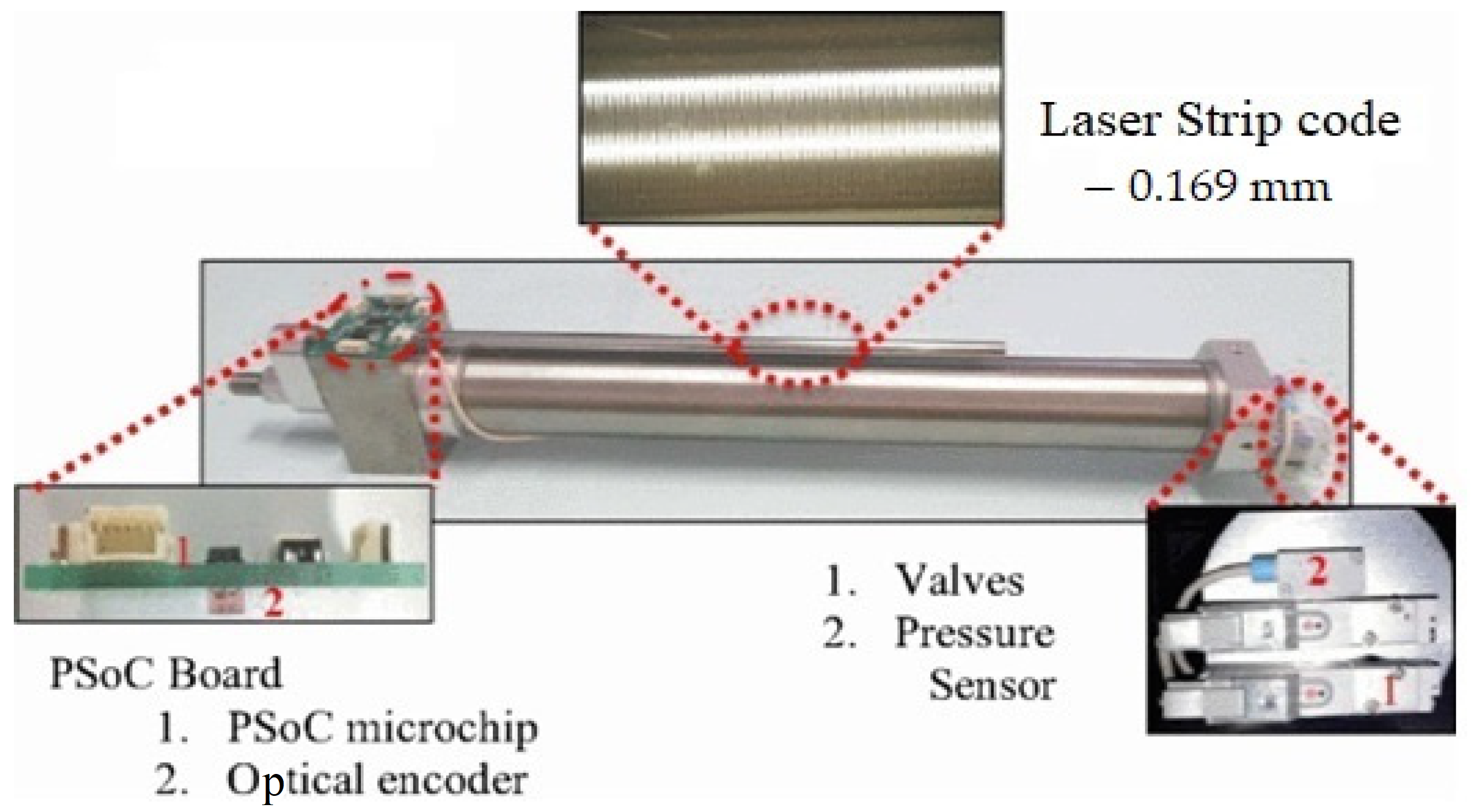
This paper proposes the design strategy for the fuzzy FOPID controller. To control the position tracking of the PA system, the fuzzy FOPID controller is developed and validated through simulation and real-time experiments.
The PID controller remains one of the most commonly used controllers recently because it can be easily developed and installed; it also works well even when there is uncertainty in the system. For the PID controller, the transfer function can be written as in Equation (2):
C ( s ) = U ( s ) E ( s ) = K p + K i S + K d S
Additionally, there are two extra design parameters in the FOPID, namely, the fractional integration order, λ, and the fractional derivative order µ [3,33,34]. Equation (3) represents the transfer function of the FOPID controller.
C ( s ) = U ( s ) E ( s ) = K p + K i S λ + K d S μ
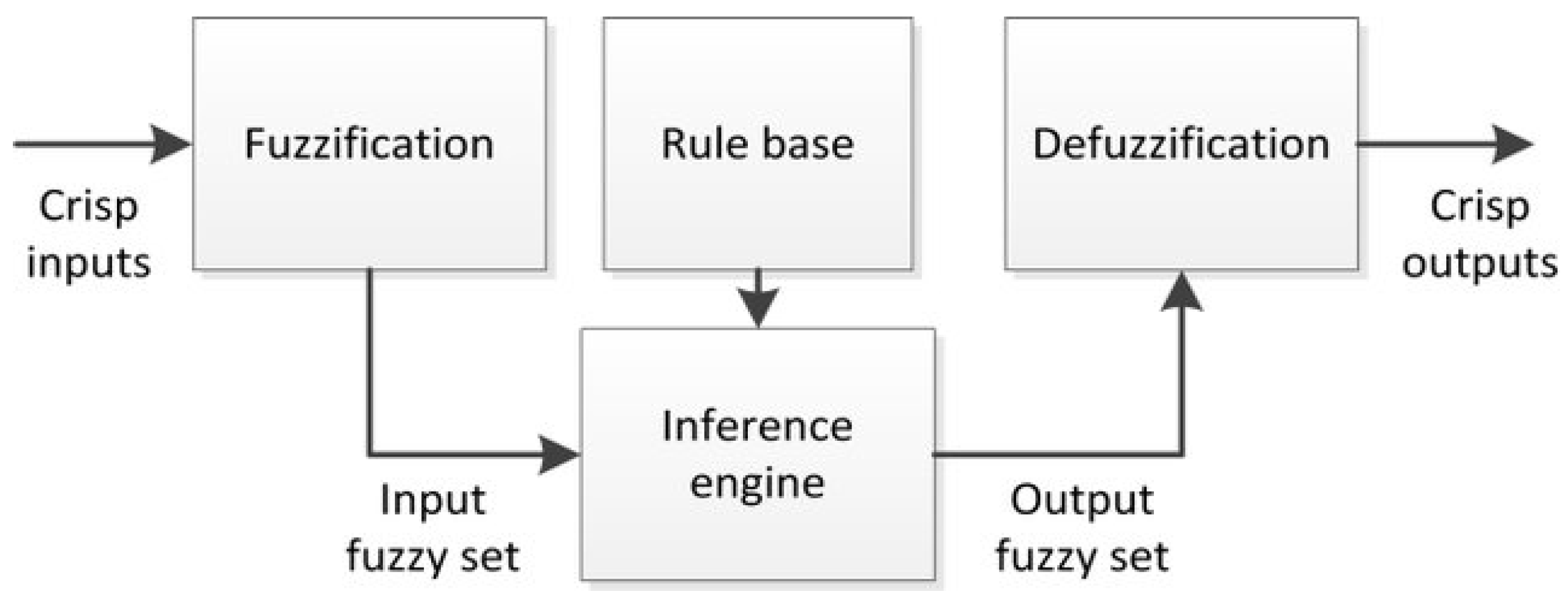
In this study, the suggested controller fuzzy FOPID is reliant on fuzzy logic control that was performed using the fuzzy logic toolbox in the MATLAB/Simulink platform. As illustrated in Figure 7, the fuzzy controller is made of three components: a fuzzification, rule basis, and defuzzification.
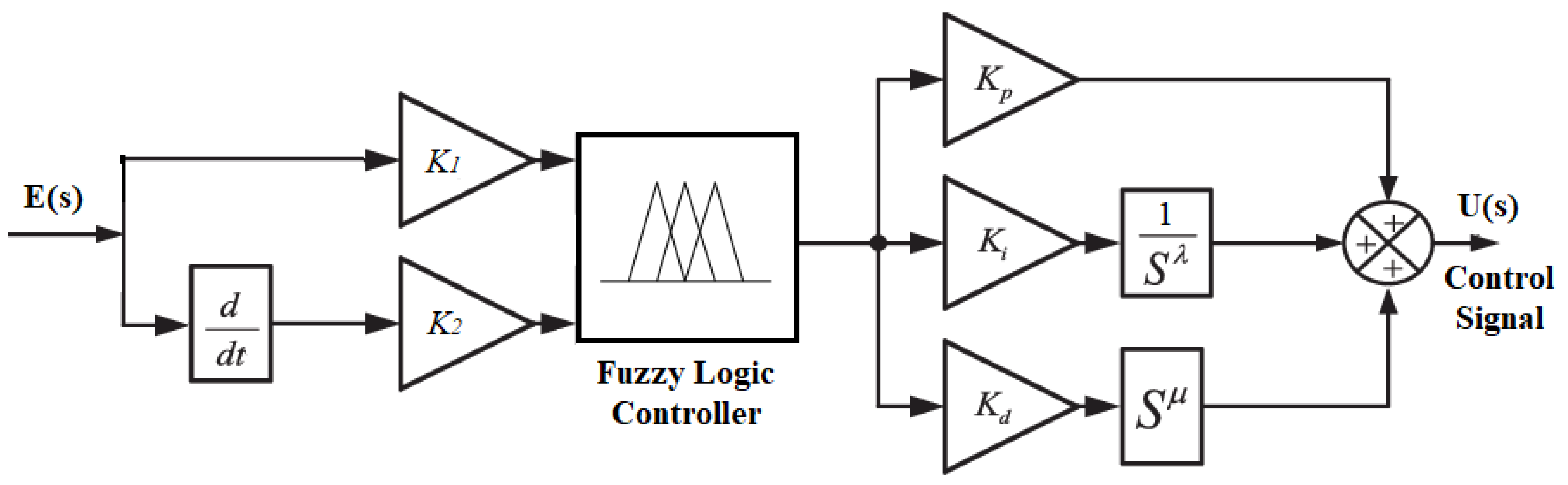
The block diagram of the proposed Fuzzy FOPID controller is shown in Figure 8. As illustrated, there are two inputs to the controller, the error (e (t)) and the rate of change of error (∆e (t)), and only one output (u). For the inputs, the scaling factor gains are (K1 and K2), while those for the output are ( K p , K i , λ , K d , and μ). To obtain the desired dynamic response of the researched system, seven parameters ( K 1 , K 2 , K p , K i , λ , K d , and μ) must be tuned.
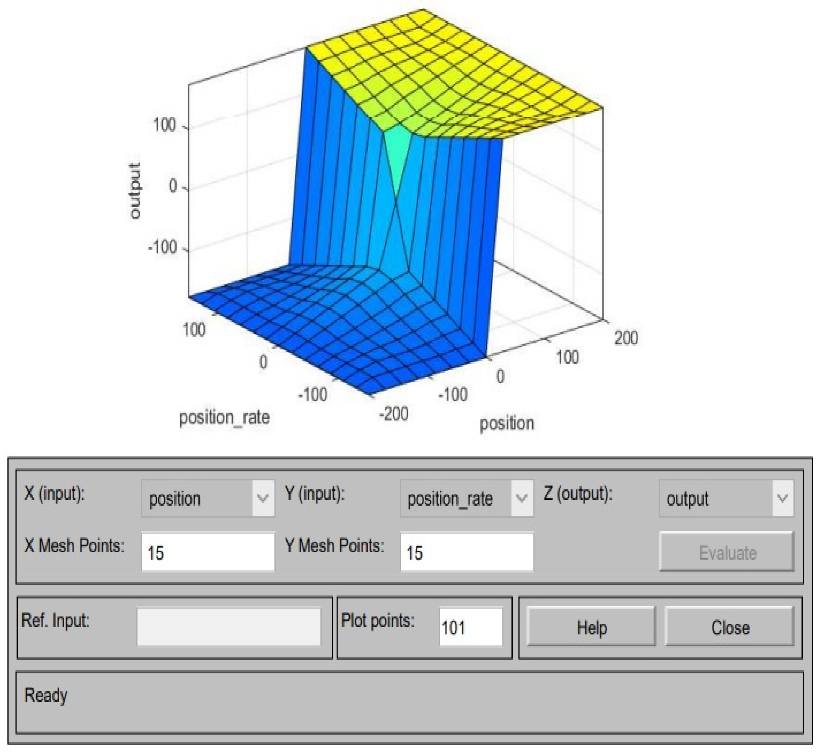
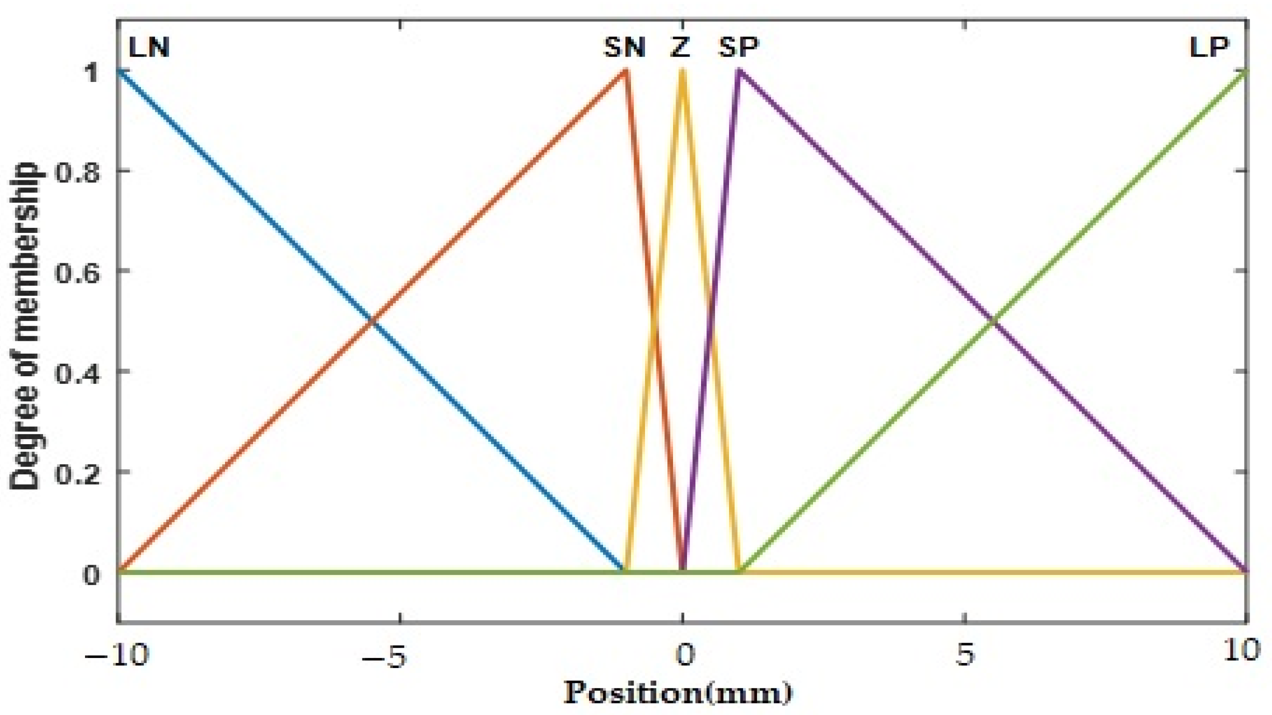
Figure 9 shows that 5 triangle membership functions (MF), namely ‘Large Negative’ (LN), ‘Small Negative’ (SN), ‘Zero’ (Z), ‘Small Positive’ (SP) and ‘Large Positive’ (LP) are utilized for input1 and input 2. The range of MF for input 1 is normalized between [−10, 10] and for input 2 is between [−5, 5], respectively. The output for the fuzzy design is singular and the linear value and the value for each variable are V2 = −255, V2k = −100, off = 0, V1k = 200, and V1 = 255. Table 2 showed that 25 rule bases are needed for the generation of the controller’s fuzzy output. The tabulated rules are derived from a detailed analysis of the researched pneumatic actuator’s dynamic behavior, which is necessary because the controller’s performance is dependent on them. Additionally, this design employs the Sugeno-type inference system for fuzzification and the “Centroid” tool for defuzzification. The surface viewer of the fuzzy is shown in Figure 10.
All design characteristics of the fuzzy FOPID controller will be discussed in this part, such as membership functions, linguistic variables, rule base, interface engine, and the defuzzification mechanism.
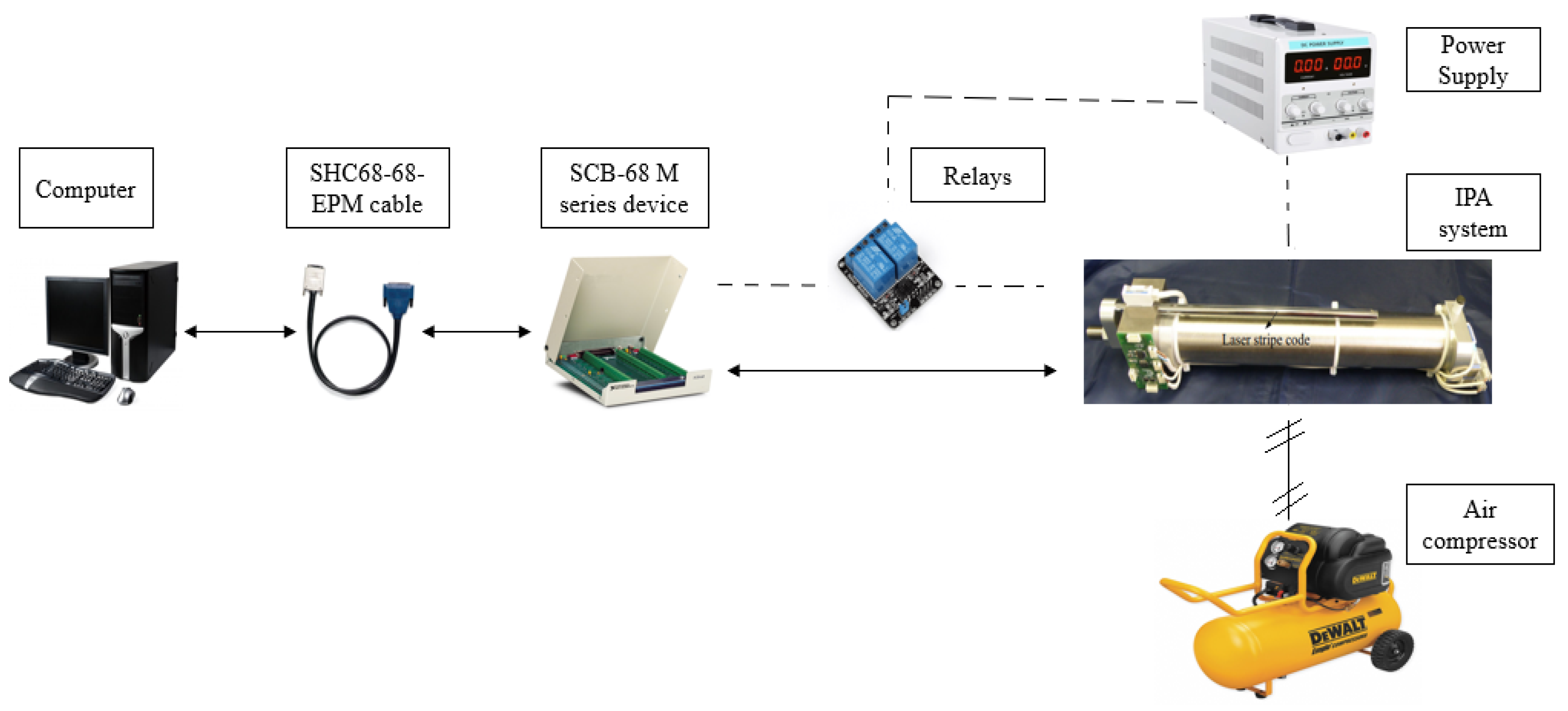
The platform used in this research is MATLAB-Simulink. 
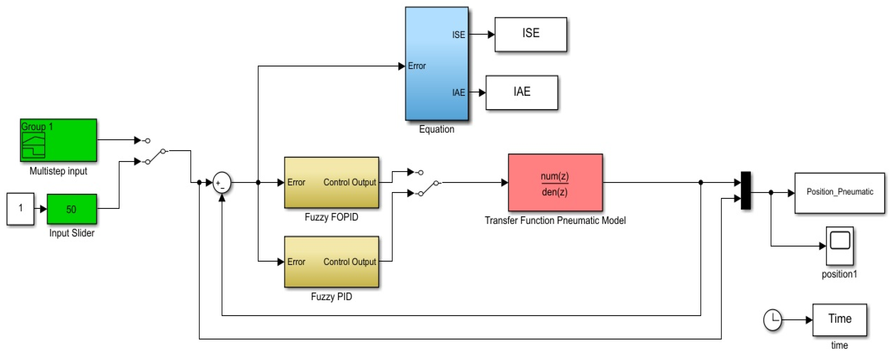
Figure 11 shows the Simulink block diagram for simulation. In this figure, the controller block consists of the fuzzy FOPID controller or fuzzy PID controller, and the IPA model as in Equation (1). Meanwhile, 
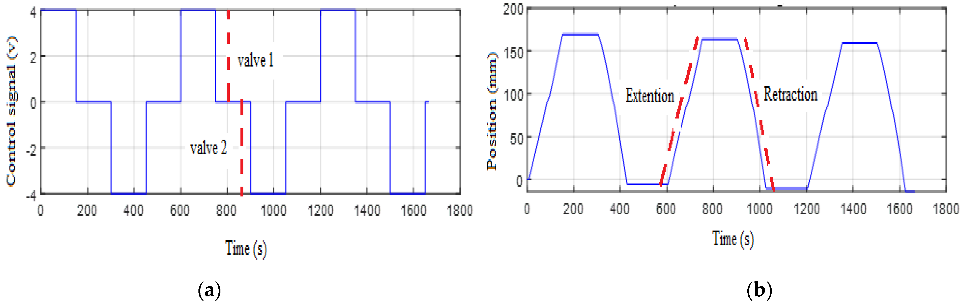
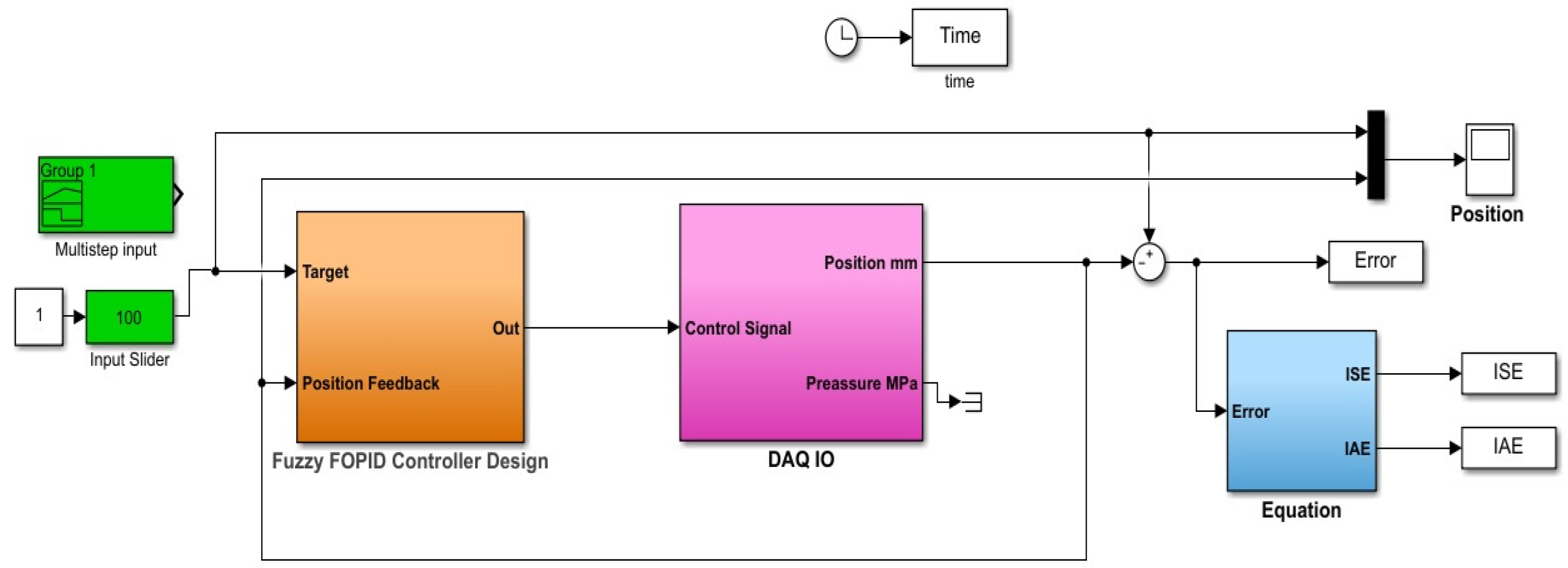
Figure 12 is the Simulink block diagram for the real-time experiment setup. The block diagram design consists of five parts which are input (position setpoint), controller part, DAQ configuration (I/O), performance index, and the output. The type of input signal used in this experiment is the same as in the simulation where the same parameters of the fuzzy FOPID and fuzzy PID controllers were implemented to the real-time experiment for validation purpose.

4. The Proposed Optimization Technique and Objective Function

PSO optimization is a heuristic search approach based on the social behavior of birds and fish schools that has gained popularity in modern times. Studies show that it is effective in nonlinear optimization problems [35,36]. When performing PSO optimization, the first step is to create the optimization target, which is the fitness function, followed by encoding of the parameters to be searched.
PSO makes use of an adaptive swarm of particles investigating promising sections of the D-dimension search space [37]. It will continue to run until the stop condition is met. The optimal particle position for the controller is determined by finding the best particle position. The popularity of PSO in recent decades can be attributed to its straightforward structure and the fact that only a few parameters are required to alter the optimization of any type of issue.
Typically, numerous fitness criteria are used to evaluate the performance of new optimization strategies, these include integral of square errors (ISE), integral absolute errors (IAE), and integral of time square errors (ITSE). The overshoot, rising time, settling time, and steady-state error are all included in these performance criteria. The IAE fitness function, as indicated in Equation (6), is employed as the metric for evaluating the output response of the system in this study:
IAE = 0 t | e ( t ) | . dt
This technique allows for the movement of a large number of particles through multidimensional search space [38]. The position and speed of the particles were updated according to Equations (5) and (6):
V ij ( t + 1 ) = W . V ij ( t ) + C 1 . rand ( pbest ( t ) X ij ( t ) ) + C 2 . rand ( gbest ( t ) X ij ( t ) )
X ij ( t + 1 ) = X ij ( t ) + V ij ( t + 1 )
where V ij ( t ) is the particle velocity, X ij ( t ) is the current particle position, W is the inertia weight, pbest(t) is the best position for the current particle, and gbest(t) is the best position obtained by all particles, while C1 and C2 are learning factors.
The PSO steps for finding the optimal values of the fuzzy FOPID parameters are summarized as follows:
  • Define the pneumatic actuator model and PSO parameters;
  • Create an initial swarm of particles with random position and velocity;
  • Calculate the fitness function in Equation (4) for each initial parameter;
  • Evaluate pbest(t) of each particle and gbest(t) of the population;
  • Update the velocity of each particle according to Equation (5);
  • Upgrade the position of each particle according to Equation (6);
  • If the number of iterations reaches the maximum, then go to the next step; otherwise, proceed to step 3;
  • Save the latest optimal parameters of pbest(t).
The values of µ and λ are tuned with the same method used for tuning the P, I, and D. We have set the search space of the algorithm from 0 to 1 for µ and λ as recommended in different references [30,34,39]. However, with the P, I, and D, the search space of the algorithm is set from 0 to 30. Table 3 illustrates the parameters of the PSO algorithm that were employed in this investigation, while Table 4 summarizes the optimal parameter values for the fuzzy FOPID as determined by PSO.
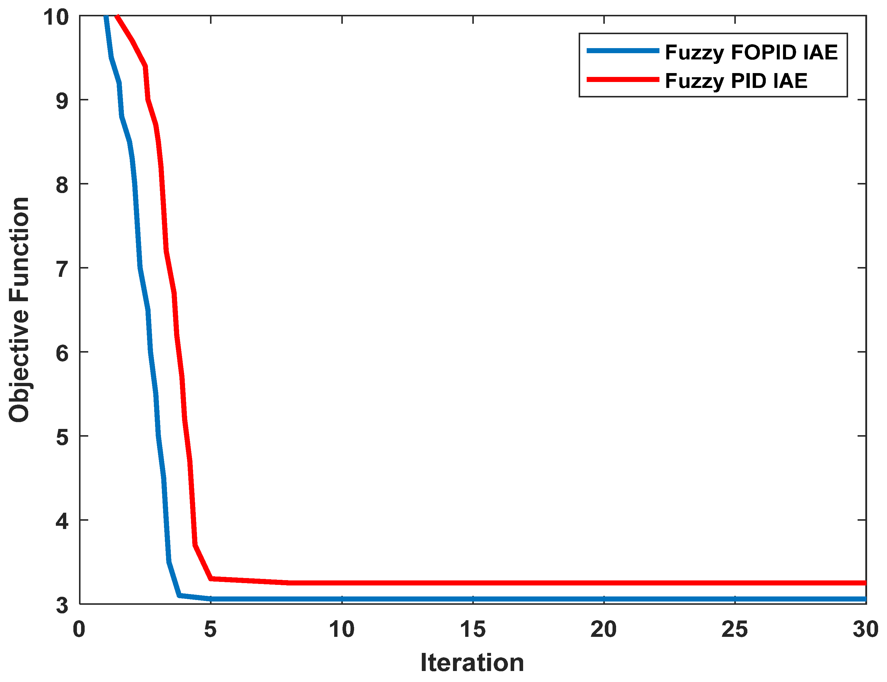
The convergence of the PSO is shown in Figure 13.

5. Results and Discussion

The aim of this work is to improve the precision and accuracy of the cylinder stroke of PAs by ensuring that it is positioned at the appropriate level; this was accomplished through simulation and experimental works in this study. Accordingly, the suggested strategy is intended to increase the system’s transient response while reducing the rise time (tr), overshoot (OS%), and settling time (ts) of the general system’s performance. The whole system is modeled in the Matlab/Simulink environment and tested in simulation and real time to evaluate the system’s performance. The optimization of the controllers was carried out by executing the algorithm with 10 agents (Np = 10) for 30 iterations (Ni = 30).
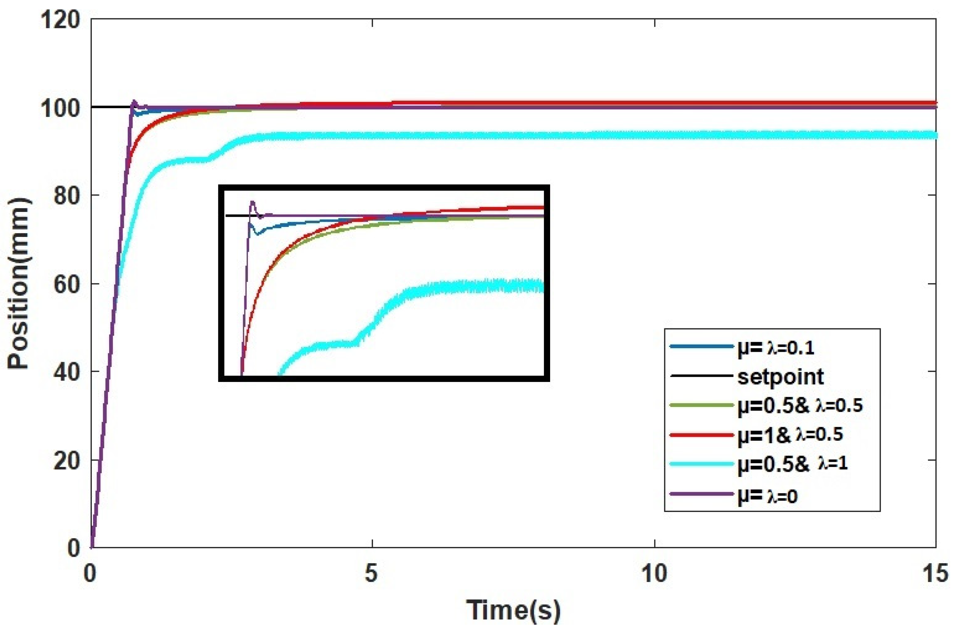
The step response of the system with the fuzzy FOPID controller for a range of different values of µ and λ is shown in Figure 14.

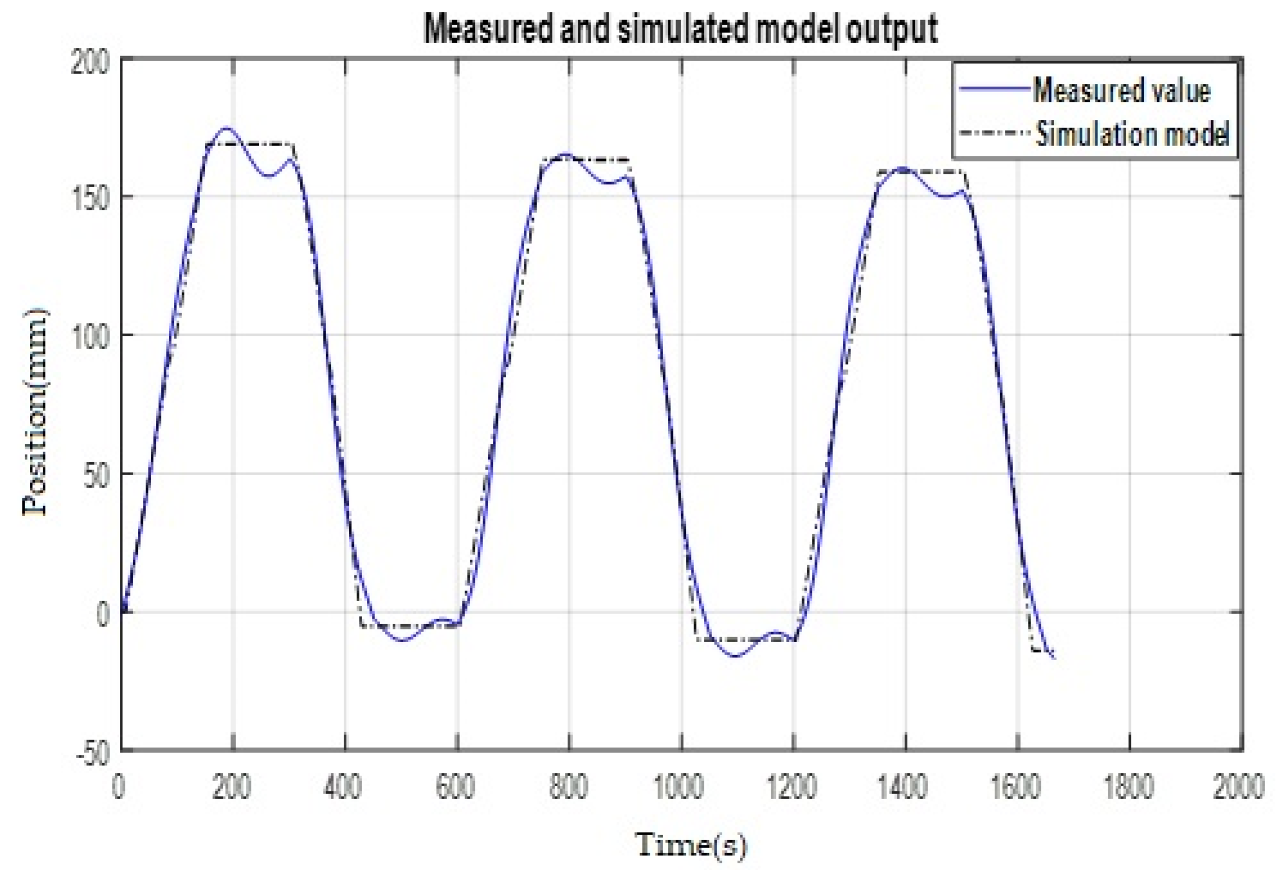
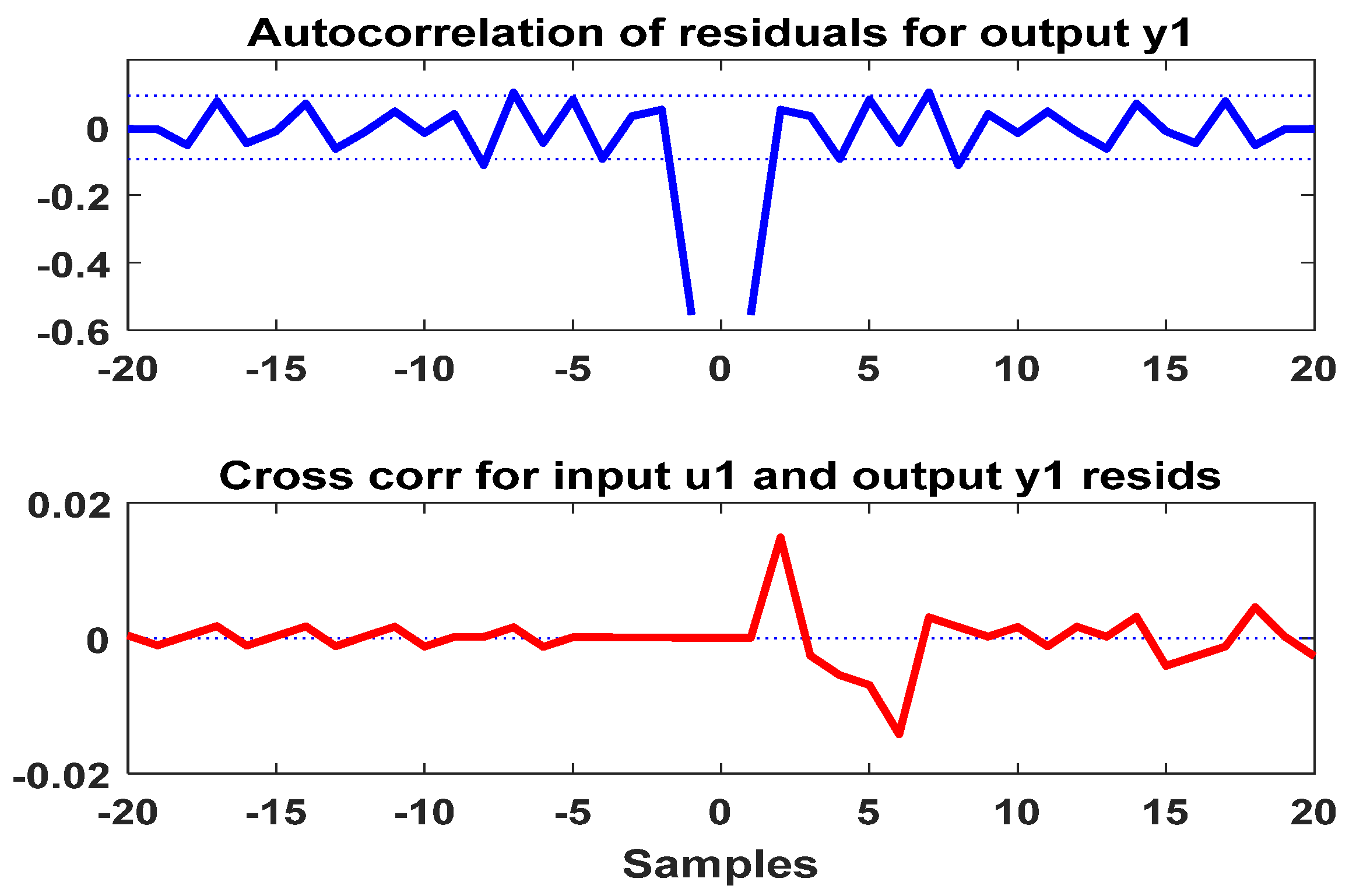
5.1. Main Results and System Identification Validation

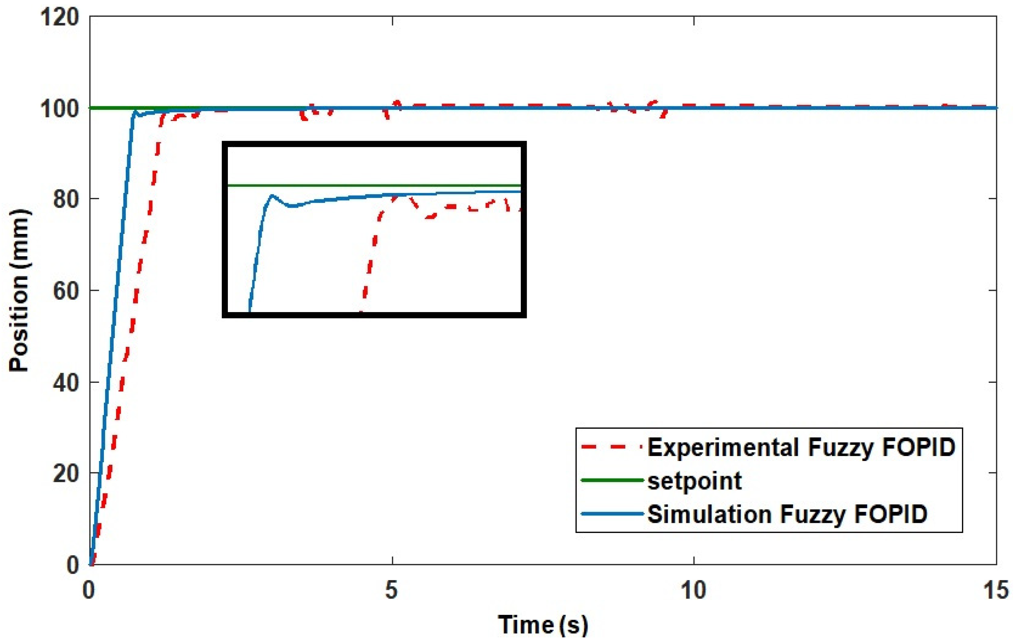
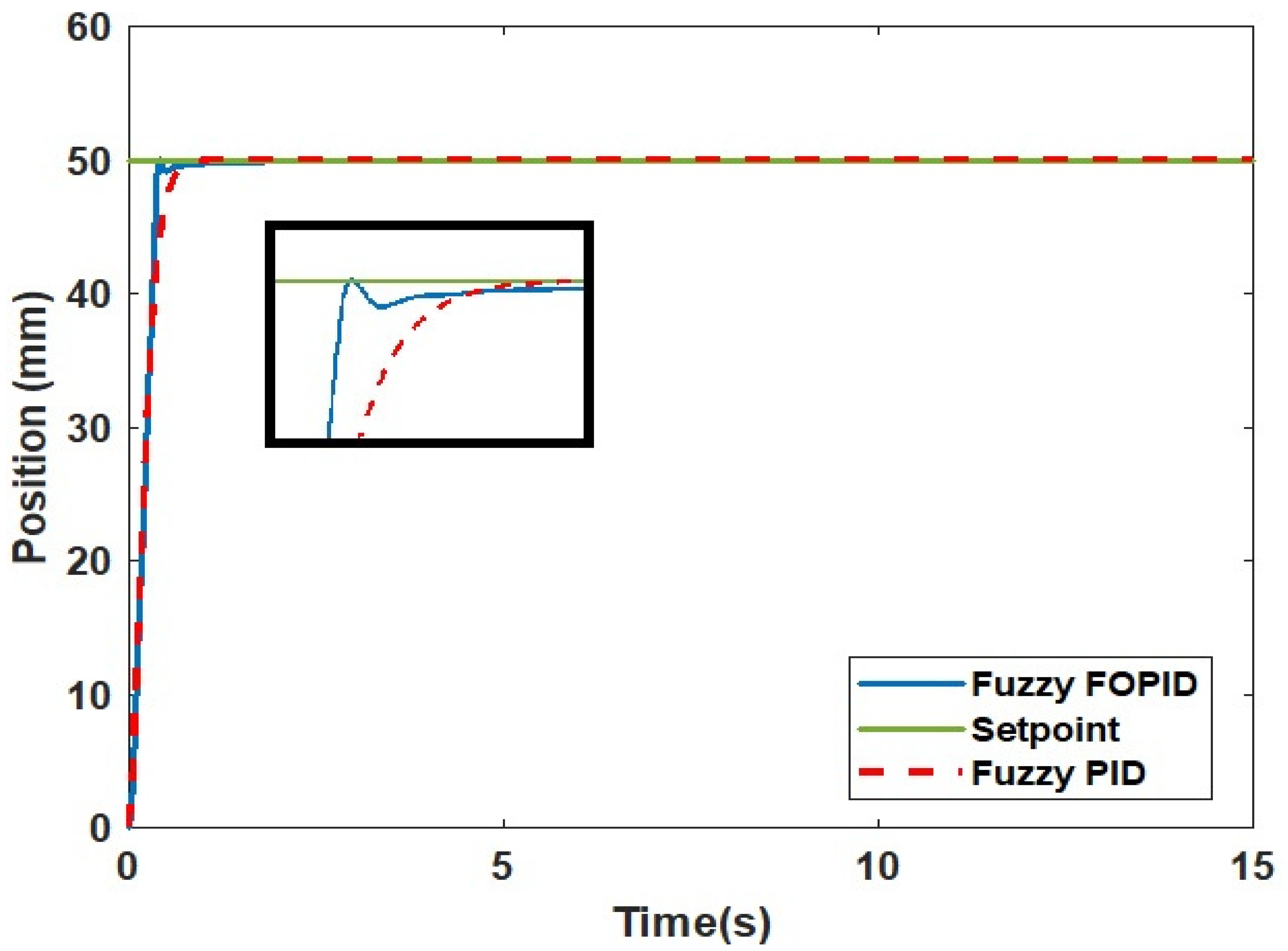
The outcome of the real and simulated studies reveals the ability of the fuzzy FOPID controller to control and maintain the position of the cylinder stroke of the IPA system at the desired positions as shown in Figure 15.

5.2. Superiority Analysis
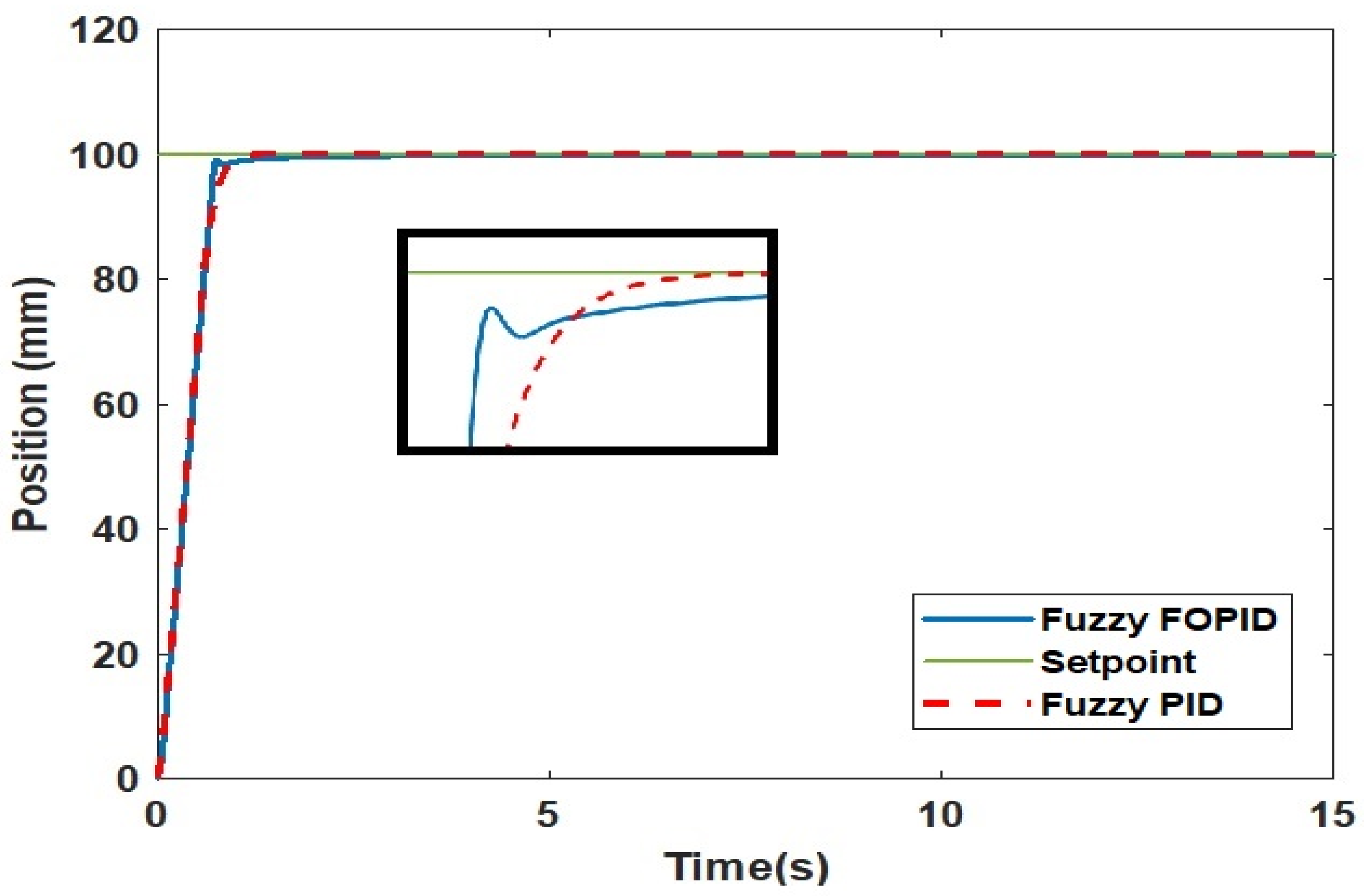
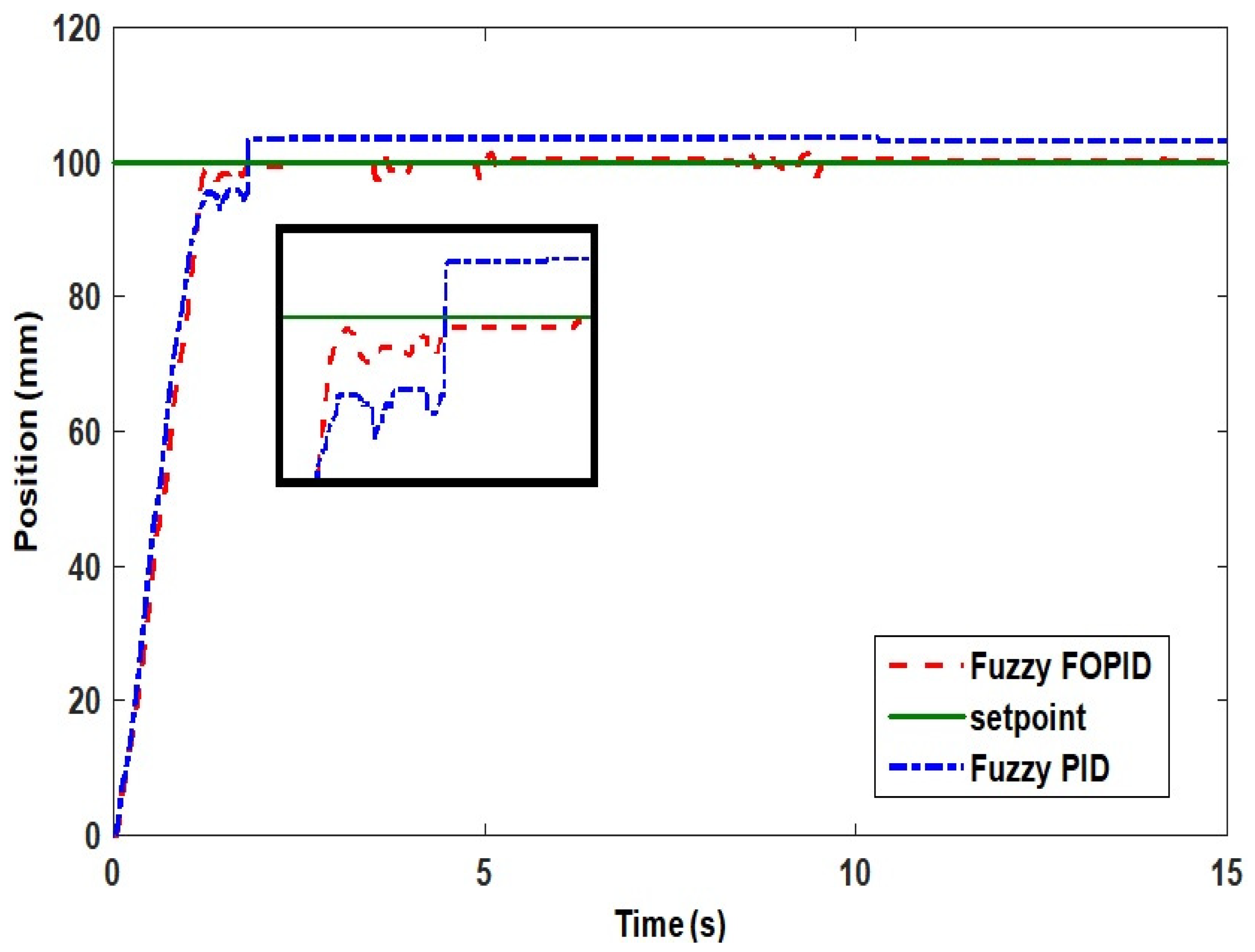
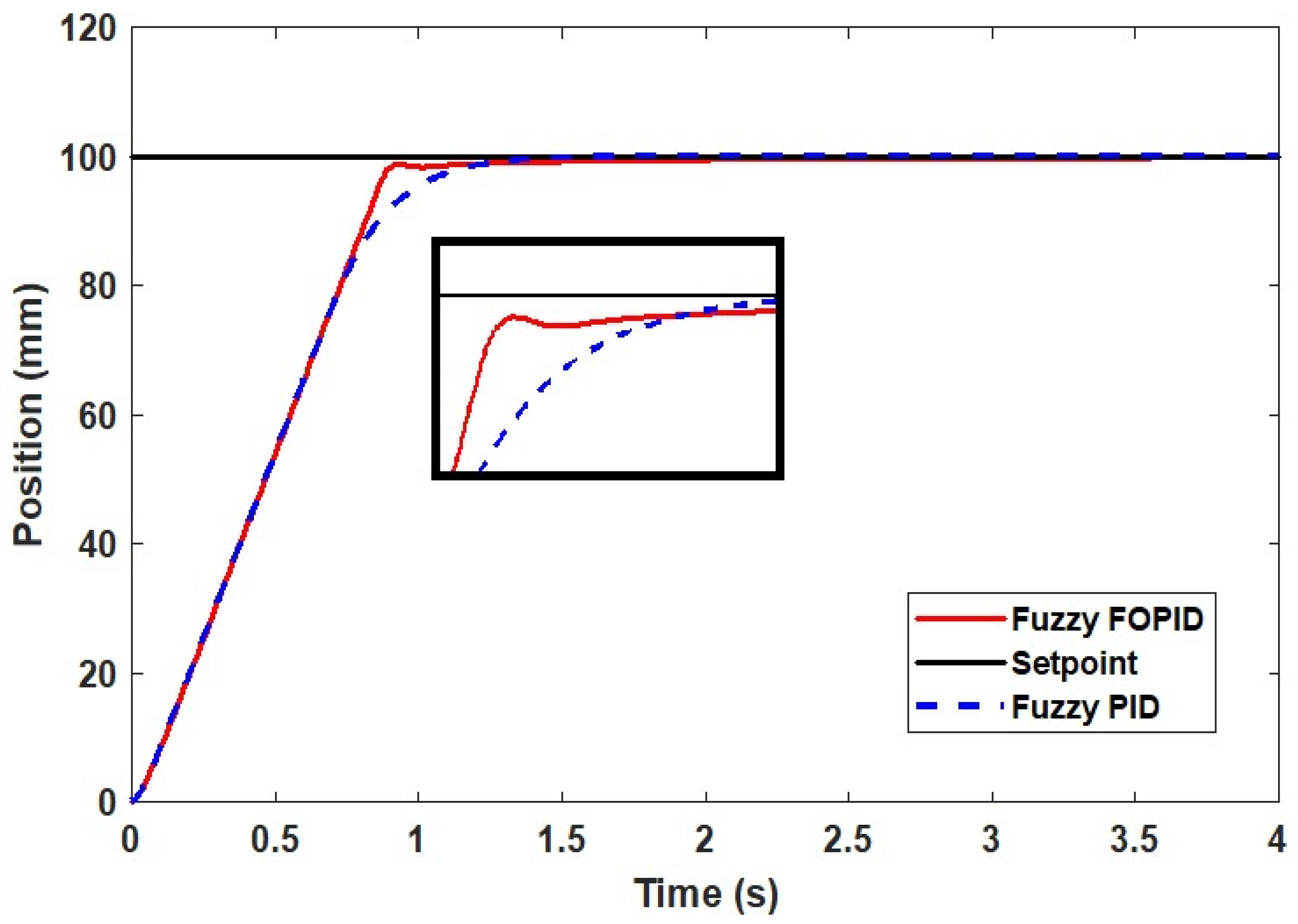
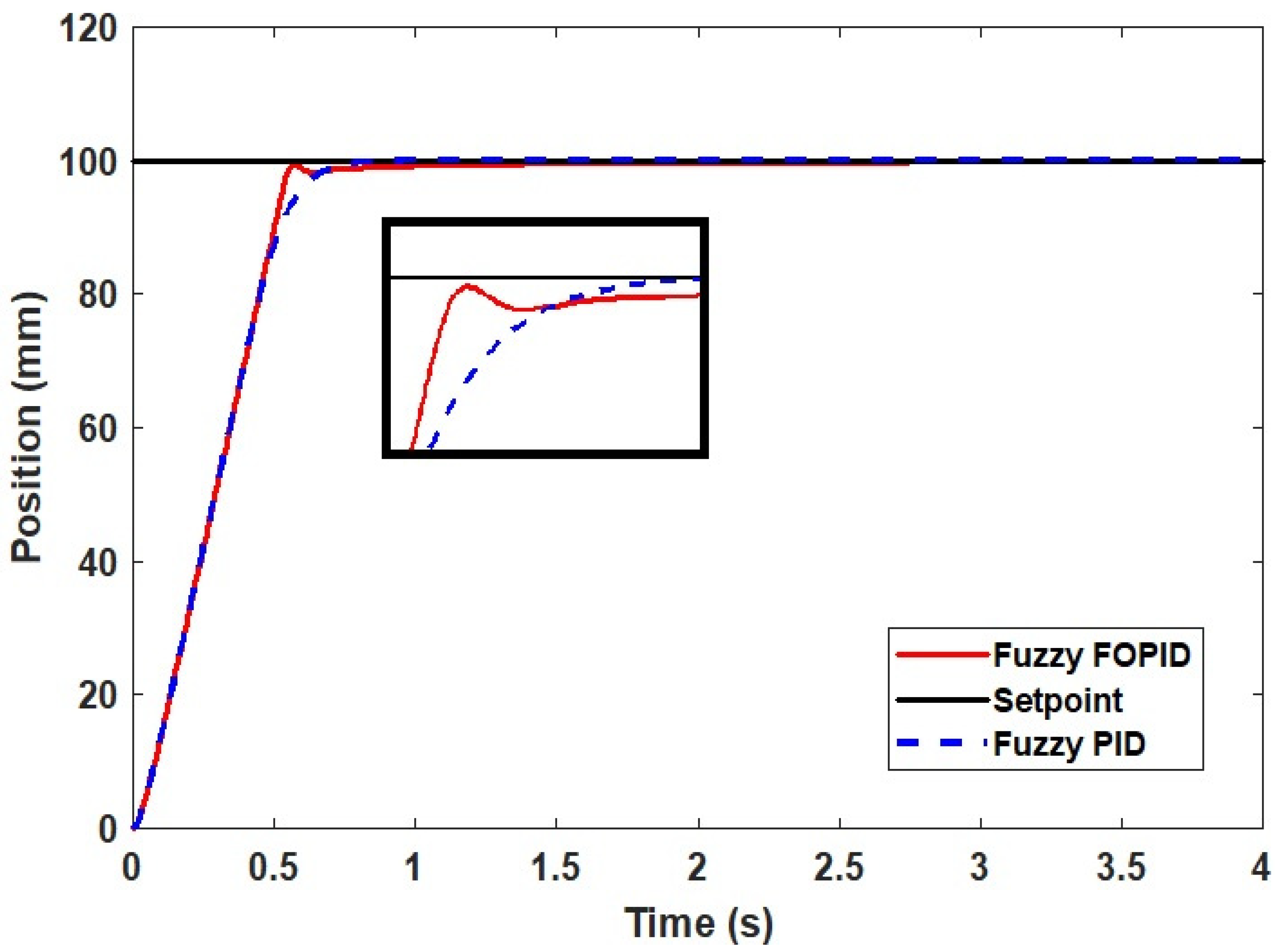
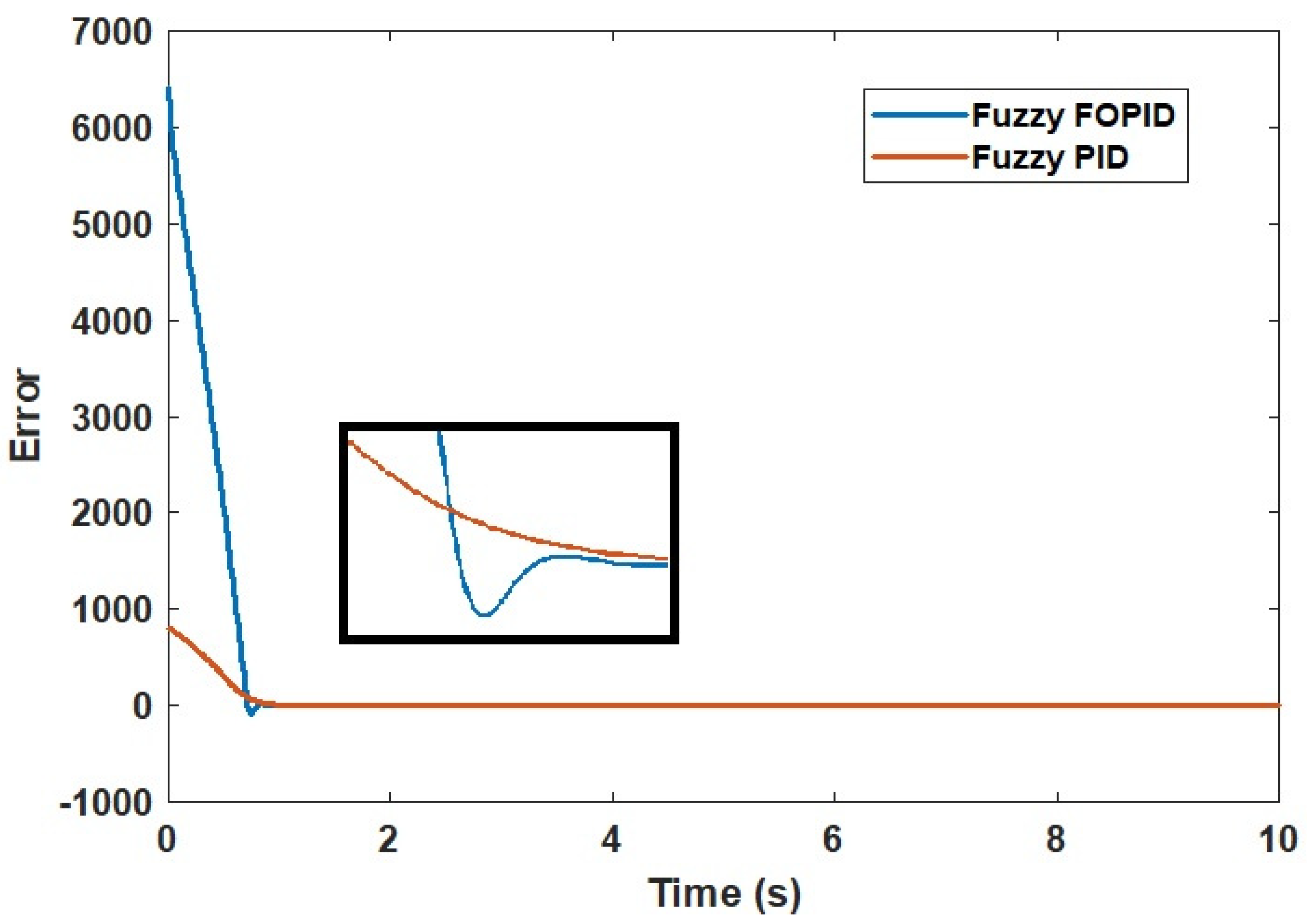
From Figure 16 and Figure 17, the fuzzy FOPID controller’s simulation performance indicates that the stroke deviated by about 0 mm as well as with the actual experiment compared with 2.5830 mm with the fuzzy PID controller as shown in Figure 18. It appears from the fuzzy PID simulation results in Figure 16 and Figure 17 that the stroke strayed from its original position by approximately 0.0002 mm within 0.0602 sec of simulation time. This simulation finding was subsequently validated in an actual experiment where the cylinder stroke was found to exceed its original position by more than 2.5830% with ess as shown in Figure 18.
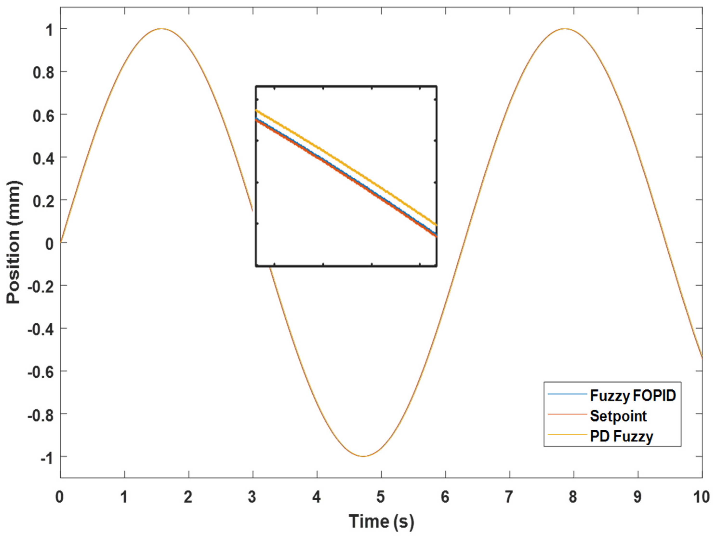
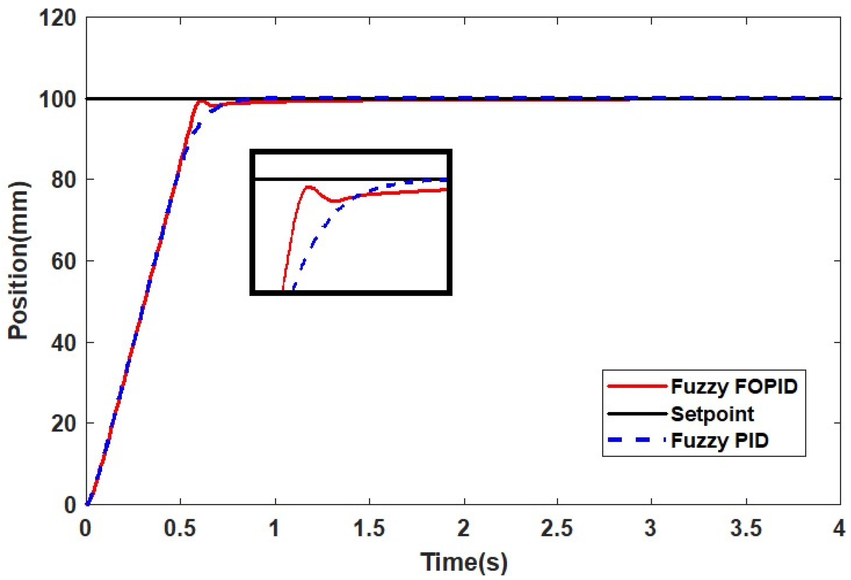
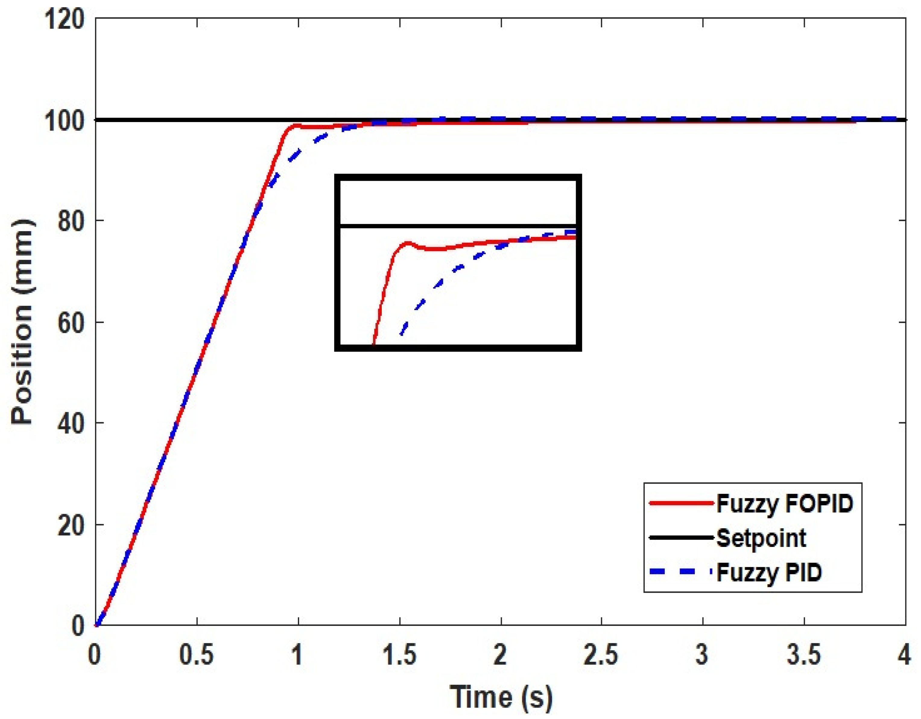
Figure 19 illustrates the performance of the fuzzy FOPID controller when testing the obtained position by the stroke with sinewave input. This demonstrates that the fuzzy FOPID controller successfully minimizes the overshoot in the system’s response.
A significant amount of the system’s response overshoot was identified as the primary issue preventing the achievement of the accurate positional control of the PAs. This could be attributed to the uncertainties in the system, such as leakage, friction, air compressibility, valve dead zone, etc.
To summarize the findings, Table 5 combines results from the modeling and experimentation of the fuzzy FOPID and fuzzy PID controllers. This clearly demonstrates the superior performance of the fuzzy FOPID controller in comparison with the fuzzy PID controller.
Figure 20 depicts the control signals of the controllers, with the smooth response of the fuzzy FOPID controller being demonstrated in comparison to the fuzzy PID controller, which prevents damage to sensitive components in the plant.
Furthermore, in order to demonstrate the superiority of the fuzzy FOPID controller, the results obtained are compared with those from published articles based on the generalized predictive controller (GPC) presented in [12], model predictive controller (MPC) presented in [40], and predictive functional controller (PFC) with the novel observer method presented in [41] employed for the same system. The performances of these controllers are shown in Table 6.
Table 6 provides further proof of the supremacy of the proposed controller over those proposed in previous works. It is noted that with the proposed fuzzy FOPID controller optimized by PSO algorithm, the overall performance of the system witnessed a remarkable improvement.

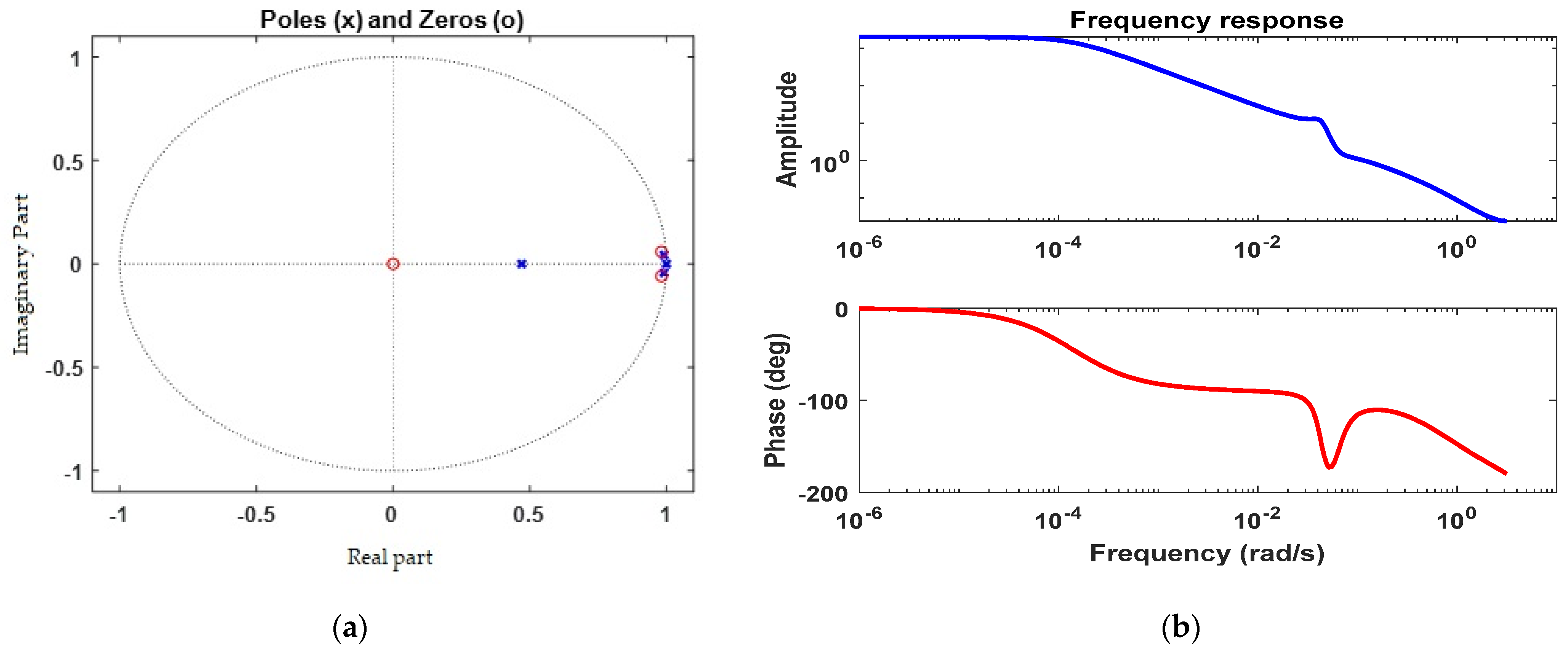
5.3. Robustness Analysis

In order to examine the robustness of the proposed fuzzy FOPID controller, the parameters of the testbed system are simultaneously varied by ±25% from their nominal values. These scenarios could represent the most common conditions of parametric uncertainties that the testbed system may experience in real-time operation. The optimal gains obtained during the normal condition will not be retuned when the model is subjected to variation in system parameters.
In case 1, the poles of the system are varied by +25% and the equation of the system is shown below:
0.0008224   Z 1 + 0.001951   Z 2 0.001172   Z 3 1.25 1.94375   Z 1 + 0.494625   Z 2 + 0.199125   Z 3
where the pole values are: P1 = −1.35, P2= −0.103 + 0.328i, and P3 = −0.103 − 0.328i, while the zero values are: Z1 = −2.87, Z2 = 0.497.
In case 2, the zeros of the system are varied by +25% and the equation of the system is shown below:
0.001028   Z 1 + 0.00243875   Z 2 0.001465   Z 3 1 1.55   Z 1 + 0.3957   Z 2 + 0.1593   Z 3
where the pole values are: P1 = −0.209, P2 = 0.764, and P3 = 1, while the zero values are: Z1 = −0.318, Z2 = 0.497.
In case 3, the poles of the system are varied by −25% and the equation of the system is shown below:
0.0008224   Z 1 + 0.001951   Z 2 0.001172   Z 3 0.75 1.16625   Z 1 + 0.296775   Z 2 + 0.119475   Z 3
where the pole values are: P1 = −0.209, P2 = 0.764, and P3 = 1, while the zero values are: Z1 = −2.87, Z2 = 0.497.
In case 4, the zeros of the system are varied by −25% and the equation of the system is shown below:
0.0006168   Z 1 + 0.00146325   Z 2 0.000879   Z 3 1 1.55   Z 1 + 0.3957   Z 2 + 0.1593   Z 3
where the pole values are: P1 = −0.209, P2 = 0.764, and P3 = 1, while the zero values are: Z1 = −2.87, Z2 = 0.497.
Figure 21, Figure 22, Figure 23 and Figure 24 and Table 7 show the dynamic response of the system with the fuzzy FOPID and fuzzy PID controllers in case 1, case 2, case 3, and case 4, respectively.
As illustrated in Figure 21, Figure 22, Figure 23 and Figure 24 and Table 7, the implemented fuzzy FOPID controller demonstrated its robustness against a wide variety of parametric uncertainties in the researched IPA system; additionally, the superiority of this controller over other controllers was examined and proven.

6. Conclusions

In this work, the fuzzy FOPID controller tuned by the PSO algorithm was implemented for a pneumatic positioning system. The addition of fractional order operators to the controller improved the controller’s robustness in terms of trajectory tracking and provided it with more flexibility in terms of parameter selection. However, tuning a large number of controller parameters has proven to be a difficult task. In order to achieve the best possible performance from the controller, the PSO algorithm was successfully applied to the tuning of a large number of controller parameters with good results. A comparative study of the fuzzy FOPID controller and the fuzzy PID controller was conducted by applying both controllers on the pneumatic actuator system in simulation and real time experiments. In comparison with the fuzzy PID controller, the fuzzy FOPID controller has superior tracking capability in terms of overshoot and settling time. Additionally, the fuzzy FOPID controller improved the fuzzy PID controller’s versatility and stability. Apart from that, the implementation of the controller tuning with PSO algorithm is considerably simpler than with old approaches because there is no requirement for derivative knowledge or difficult mathematical equations, as there is with the traditional methods.

Author Contributions

Conceptualization, M.N.M. and A.A.M.F.; methodology, M.N.M. and A.A.M.F.; software, M.N.M. and A.A.M.F.; validation, M.N.M., A.A.M.F. and S.S.; formal analysis, M.N.M. and S.S.; investigation, M.N.M. and A.A.M.F.; resources, M.N.M. and M.S.; data curation, S.S.; writing—original draft preparation, M.N.M. and M.S.; writing—review and editing, M.N.M. and M.S.; visualization, S.S.; supervision, A.A.M.F. and S.S.; project administration, A.A.M.F. and S.S.; funding acquisition, M.N.M. and M.S. All authors have read and agreed to the published version of the manuscript.

Funding

This research received no external funding.

Institutional Review Board Statement

Not applicable.

Informed Consent Statement

Not applicable.

Data Availability Statement

Not applicable.

Acknowledgments

The authors thank Cardiff University for paying the APC towards publishing thi manuscript. Also, the research has been carried out under program Research Excellence Consortium (JPT (BPKI) 1000/016/018/25 (57)) with the title Consortium of Robotics Technology for Search and Rescue Operations (CORTESRO) provided by Ministry of Higher Education Malaysia (MOHE). The authors also would like to acknowledge of Universiti Teknologi Malaysia (UTM), vote no (4L930) for always support on provided facilities to complete this research.

Conflicts of Interest

The authors declare no conflict of interest.

References

  1. Osman, K.; Faudzi, A.A.M.; Rahmat, M.F.; Kai, C.C.; Suzumori, K. Design and development of Ankle-Foot Rehabilitation Exerciser (AFRE) system using pneumatic actuator. J. Telecommun. Electron. Comput. Eng. 2018, 10, 137–143. [Google Scholar]
  2. Sulaiman, S.F.; Rahmat, M.F.; Faudzi, A.A.; Osman, K.; Samsudin, S.I.; Abidin AF, Z.; Sulaiman, N.A. Pneumatic positioning control system using constrained model predictive controller: Experimental repeatability test. Int. J. Electr. Comput. Eng. 2021, 11, 3913–3923. [Google Scholar] [CrossRef]
  3. Muftah, M.N.; Faudzi, A.A.M. Tracking Performance of Pneumatic Position Using Fractional-Order PI λ D μ Controller. IOP Conf. Ser. Mater. Sci. Eng. 2021, 1153, 012011. [Google Scholar] [CrossRef]
  4. Muftah, M.N.; Xuan, W.L.; Athif, A.; Faudzi, M. ARX, ARMAX, Box-Jenkins, Output-Error, and Hammerstein Models for Modeling Intelligent Pneumatic Actuator (IPA) System. J. Integr. Adv. Eng. 2021, 1, 81–88. [Google Scholar] [CrossRef]
  5. Mahyudin, N.K.B.; Zaini, Z.H.; Osman, K.; Sulaiman, S.F. Tracking Performance of Pneumatic Position Using Generalized Minimum Variance Controller (Gmvc). J. Eng. Health Sci. 2018, 2, 79–92. [Google Scholar]
  6. Sulaiman, S.F.; Rahmat, M.F.; Faudzi, A.A.M.; Osman, K. A new technique to reduce overshoot in pneumatic positioning system. Telkomnika Telecommun. Comput. Electron. Control. 2019, 17, 2607–2616. [Google Scholar] [CrossRef]
  7. Faudzi, A.A.M.; Suzumori, K.; Wakimoto, S. Development of an intelligent chair tool system applying new intelligent pneumatic actuators. Adv. Robot. 2010, 24, 1503–1528. [Google Scholar] [CrossRef] [Green Version]
  8. Faudzi, A.À.M.; Suzumori, K.; Wakimoto, S. Development of Pneumatic Actuated Seating System to aid chair design. In Proceedings of the 2010 IEEE/ASME International Conference on Advanced Intelligent Mechatronics, Montreal, QC, Canada, 6–9 July 2010; pp. 1035–1040. [Google Scholar] [CrossRef]
  9. Faudzi, A.A.M.; Osman, K.B.; Rahmat, M.F.; Mustafa, N.D.; Azman, M.A.; Suzumori, K. Controller design for simulation control of Intelligent Pneumatic Actuators (IPA) system. Procedia Eng. 2012, 41, 593–599. [Google Scholar] [CrossRef] [Green Version]
  10. Faudzi, A.A.M.; Osman, K.; Rahmat, M.F.A.; Suzumori, K.; Mustafa, N.D.; Azman, M.A. Real-time position control of intelligent pneumatic actuator (IPA) system using optical encoder and pressure sensor. Sens. Rev. 2013, 33, 341–351. [Google Scholar] [CrossRef]
  11. Faudzi, A.A.M.; Mustafa, N.D.; Osman, K.B.; Azmana, M.A.; Suzumori, K. GPC controller design for an Intelligent Pneumatic Actuator. Procedia Eng. 2012, 41, 657–663. [Google Scholar] [CrossRef]
  12. Faudzi, A.A.M.; Mustafa, N.D.; Azman, M.A.; Osman, K. Position tracking of pneumatic actuator with loads by using predictive and fuzzy logic controller. Adv. Mater. Res. 2014, 903, 259–266. [Google Scholar] [CrossRef]
  13. Faudzi, A.M.; Osman, K.; Rahmat, M.F.; Mustafa, N.D.; Azman, M.A.; Suzumori, K. Nonlinear mathematical model of an Intelligent Pneumatic Actuator (IPA) systems: Position and force controls. In Proceedings of the 2012 IEEE/ASME International Conference on Advanced Intelligent Mechatronics (AIM), Kaohsiung, Taiwan, 11–14 July 2012; pp. 1105–1110. [Google Scholar] [CrossRef] [Green Version]
  14. Osman, K.; Athif, A.; Faudzi, M.; Rahmat, M.F.; Hikmat, O.F.; Suzumori, K. Predictive Functional Control with Observer (PFC-O) Design and Loading Effects Performance for a Pneumatic System. Arab. J. Sci. Eng. 2015, 40, 633–643. [Google Scholar] [CrossRef]
  15. Osman, K.; Faudzi, A.A.M.; Rahmat, M.F.; Mustafa, N.D.; Suzumori, K. Predictive functional controller design for pneumatic actuator with stiffness characteristic. In Proceedings of the 2013 IEEE/SICE International Symposium on System Integration, Kobe, Japan, 15–17 December 2013; pp. 641–646. [Google Scholar] [CrossRef]
  16. Faudzi, A.A.M.; Mustafa, N.D.; Osman, K. Force control for a pneumatic cylinder using generalized predictive controller approach. Math. Probl. Eng. 2014, 2014, 261829. [Google Scholar] [CrossRef]
  17. Podlubny, I. Fractional-order systems and PIλDµ controllers. IEEE Trans. Automat. Contr. 1999, 44, 208–214. [Google Scholar] [CrossRef]
  18. Sikander, A.; Thakur, P.; Bansal, R.C.; Rajasekar, S. A novel technique to design cuckoo search based FOPID controller for AVR in power systems. Comput. Electr. Eng. 2018, 70, 261–274. [Google Scholar] [CrossRef]
  19. Vinagre, B.M.; Podlubny, I.; Dorcak, L.; Feliu, V. On Fractional PID Controllers: A Frequency Domain Approach. IFAC Proc. Vol. 2000, 33, 51–56. [Google Scholar] [CrossRef]
  20. Petras, I. The Fractional-Order Controllers: Methods for Their Synthesis and Application. arXiv 2000, arXiv:preprint math/0004064. [Google Scholar]
  21. Pan, I.; Das, S. Frequency domain design of fractional order PID controller for AVR system using chaotic multi-objective optimization. Int. J. Electr. Power Energy Syst. 2013, 51, 106–118. [Google Scholar] [CrossRef] [Green Version]
  22. Rajasekhar, A.; Jatoth, R.K.; Abraham, A. Design of intelligent PID/PIλDμ speed controller for chopper fed DC motor drive using opposition based artificial bee colony algorithm. Eng. Appl. Artif. Intell. 2014, 29, 13–32. [Google Scholar] [CrossRef]
  23. Dumlu, A.; Erenturk, K. Trajectory tracking control for a 3-DOF parallel manipulator using fractional-order PIλDμ control. IEEE Trans. Ind. Electron. 2014, 61, 3417–3426. [Google Scholar] [CrossRef]
  24. Luo, Y.; Chen, Y. Stabilizing and robust fractional order PI controller synthesis for first order plus time delay systems. Automatica 2012, 48, 2159–2167. [Google Scholar] [CrossRef]
  25. Altintas, G.; Aydin, Y. Optimization of Fractional and Integer Order PID Parameters using Big Bang Big Crunch and Genetic Algorithms for a MAGLEV System. IFAC-PapersOnLine 2017, 50, 4881–4886. [Google Scholar] [CrossRef]
  26. Das, S.; Pan, I.; Das, S.; Gupta, A. A novel fractional order fuzzy PID controller and its optimal time domain tuning based on integral performance indices. Eng. Appl. Artif. Intell. 2012, 25, 430–442. [Google Scholar] [CrossRef] [Green Version]
  27. Moradi, M. A genetic-multivariable fractional order PID control to multi-input multi-output processes. J. Process. Control 2014, 24, 336–343. [Google Scholar] [CrossRef]
  28. Shouran, M.; Anayi, F.; Packianather, M. The bees algorithm tuned sliding mode control for load frequency control in two-area power system. Energies 2021, 14, 5701. [Google Scholar] [CrossRef]
  29. Sharma, R.; Gaur, P.; Mittal, A.P. Performance analysis of two-degree of freedom fractional order PID controllers for robotic manipulator with payload. ISA Trans. 2015, 58, 279–291. [Google Scholar] [CrossRef]
  30. Rajesh, R. Optimal tuning of FOPID controller based on PSO algorithm with reference model for a single conical tank system. SN Appl. Sci. 2019, 1, 1–14. [Google Scholar] [CrossRef] [Green Version]
  31. Pan, I.; Das, S.; Gupta, A. Tuning of an optimal fuzzy PID controller with stochastic algorithms for networked control systems with random time delay. ISA Trans. 2011, 50, 28–36. [Google Scholar] [CrossRef]
  32. Özdemir, M.T.; Öztürk, D.; Eke, I.; Çelik, V.; Lee, K.Y. Tuning of Optimal Classical and Fractional Order PID Parameters for Automatic Generation Control Based on the Bacterial Swarm Optimization. IFAC-PapersOnLine 2015, 48, 501–506. [Google Scholar] [CrossRef]
  33. Muftah, M.N.; Faudzi, A.A.M. Fractional-Order PIλDμ Controller for Position Control of Intelligent Pneumatic Actuator (IPA) System; Springer: Singapore, 2021; Volume 3. [Google Scholar]
  34. Ghazbi, S.N.; Akbarzadeh, A.; Kardan, I. Statistically optimized FOPID for output force control of SEAs. Adv. Robot. 2018, 32, 231–241. [Google Scholar] [CrossRef]
  35. Soundarrajan, A.; Sumathi, S.; Sundar, C. Particle swarm optimization based LFC and AVR of autonomous power generating system. IAENG Int. J. Comput. Sci. 2010, 37, 37-1. [Google Scholar]
  36. Hasan, F.A.; Rashad, L.J. Fractional-order PID controller for permanent magnet DC motor based on PSO algorithm. Int. J. Power Electron. Drive Syst. 2019, 10, 1724–1733. [Google Scholar] [CrossRef]
  37. Kim, D.H. A swarm system design based on a modified particle swarm algorithm for a self-organizing scheme. Adv. Robot. 2006, 20, 913–932. [Google Scholar] [CrossRef]
  38. Mishra, A.K.; Das, S.R.; Ray, P.K.; Mallick, R.K.; Mohanty, A.; Mishra, D.K. PSO-GWO Optimized Fractional Order PID Based Hybrid Shunt Active Power Filter for Power Quality Improvements. IEEE Access 2020, 8, 74497–74512. [Google Scholar] [CrossRef]
  39. Shouran, M.; Alsseid, A.M. Cascade of Fractional Order PID based PSO Algorithm for LFC in Two-Area Power System. In Proceedings of the ICERA 2021: 2021 3rd International Conference on Electronics Representation and Algorithm, Yogyakarta, Indonesia, 29–30 July 2021; IEEE: Piscataway, NJ, USA, 2021; pp. 1–6. [Google Scholar]
  40. Sulaiman, S.F.; Rahmat, M.F.; Faudzi, A.A.M.; Osman, K.; Salim, S.N.S.; Samsudin, S.I.; Azira, A.R. Enhanced position control for pneumatic system by applying constraints in MPC algorithm. Int. J. Electr. Comput. Eng. 2017, 7, 1633–1642. [Google Scholar] [CrossRef]
  41. Azira, A.R.; Osman, K.; Samsudin, S.I.; Sulaiman, S.F. Predictive Functional Controller (PFC) with Novel Observer Method for Pneumatic Positioning System. J. Telecommun. Electron. Comput. Eng. 2018, 10, 119–124. [Google Scholar]
Figure 1. The experimental setup for the system.
Energies 15 03757 g001
Figure 2. The pneumatic cylinder and its parts.
Energies 15 03757 g002
Figure 3. (a) input data and (b) output data.
Energies 15 03757 g003
Figure 4. The measured and simulated model output.
Energies 15 03757 g004
Figure 5. (a) Poles and zeroes; (b) frequency response.
Energies 15 03757 g005
Figure 6. Model residual.
Energies 15 03757 g006
Figure 7. The measured and simulated model output.
Energies 15 03757 g007
Figure 8. Block diagram of the fuzzy FOPID controller.
Energies 15 03757 g008
Figure 9. Inputs and output membership functions.
Energies 15 03757 g009
Figure 10. The surface viewer of the fuzzy.
Energies 15 03757 g010
Figure 11. Simulink diagram for simulation.
Energies 15 03757 g011
Figure 12. Simulink diagram for real-time experiment.
Energies 15 03757 g012
Figure 13. The convergence of the PSO.
Energies 15 03757 g013
Figure 14. Step response of the system with different values of µ and λ.
Energies 15 03757 g014
Figure 15. Fuzzy FOPID simulation and experimental performances.
Energies 15 03757 g015
Figure 16. Fuzzy FOPID and fuzzy PID simulation performances (100 mm fixed position).
Energies 15 03757 g016
Figure 17. Fuzzy FOPID and fuzzy PID simulation performances (50 mm fixed position).
Energies 15 03757 g017
Figure 18. Fuzzy FOPID and fuzzy PID experimental performances.
Energies 15 03757 g018
Figure 19. Simulation performances for the IPA with sinewave input.
Energies 15 03757 g019
Figure 20. Control signal of the fuzzy FOPID and PD fuzzy.
Energies 15 03757 g020
Figure 21. Dynamic response of the system with the fuzzy FOPID and fuzzy PID controllers under parametric uncertainties, case 1.
Energies 15 03757 g021
Figure 22. Dynamic response of the system with the fuzzy FOPID and fuzzy PID controllers under parametric uncertainties, case 2.
Energies 15 03757 g022
Figure 23. Dynamic response of the system with the fuzzy FOPID and fuzzy PID controllers under parametric uncertainties, case 3.
Energies 15 03757 g023
Figure 24. Dynamic response of the system with the fuzzy FOPID and fuzzy PID controllers under parametric uncertainties, case 4.
Energies 15 03757 g024
Table 1. The cylinder stroke’s movements based on the valve’s operations.
Valve ConditionCylinder Stroke Movements
V 1V 2
OffOffStop
OffOnRetract movement
OnOffExtend movement
OnOnWithout operation
Table 2. The suggested controller design’s fuzzy rule base.
Error Rate Δe(t)Error e(t)
LNSNOffSPLP
LNV2V2V2V1V1
SNV2V2kV2kV1kV1
OffV2V2koffV1kV1
SPV2V2kV1kV1kV1
LPV2V2V1V1V1
Table 3. The parameters of the proposed PSO algorithm.
ParameterSocial Coefficient, sCognitive Coefficient, cInertia Weight, iwDimension of the Problem, NdUpper Boundary, uPLower Boundary, lP
Value1.421.420.97(30, 30, 30,30, 1, 30, 1)(0.01, 0.01,0.01,0.01 0.01, 0.01, 0.01)
Table 4. The optimal values of the fuzzy FOPID controller.
CriteriaKpKiKdλµ
FFOPID251100.10.1
Table 5. Comparison between fuzzy PID and fuzzy FOPID performances (Fixed at 100 mm).
Criteria tr (s)ts (s)OS%ISEIAE
SimulationFuzzy FOPID0.05620.078400.85233.0676
Fuzzy PID0.06020.09280.00022.3163.2450
ExperimentFuzzy FOPID0.093870.95203≈0--
Fuzzy PID0.106790.166642.5830--
Table 6. Comparison between the fuzzy FOPID and other controllers’ performance.
CriteriaSimulationReal Time
tr (s)ts (s)OS%esstr (s)ts (s)OS%ess
Fuzzy FOPID0.05620.0784000.093870.9520300
GPC0.1650.250.70.30.66380.916200.121
MPC0.53300.73310.012200.66331.16662.06360.66
PFC-O0.56650.8166≈0≈00.65680.9455≈00.56
Table 7. Comparison between the fuzzy FOPID and other controllers’ performance.
CriteriaCase 1 (Poles +25%)Case 2 (Zeros +25%)Case 3 (Poles −25%)Case 4 (Zeros −25%)
Tr (s)Ts (s)OS%Tr (s)Ts (s)OS%Tr (s)Ts (s)OS%Tr (s)Ts (s)OS%
Fuzzy FOPID0.07000.089400.04500.057900.04230.054400.07470.095300
Fuzzy PID0.07480.1149≈00.04740.0708≈00.04430.0659≈00.07990.12313≈0
Publisher’s Note: MDPI stays neutral with regard to jurisdictional claims in published maps and institutional affiliations.

