Article

Investigation on the Fracture-Pore Evolution and Percolation Characteristics of Oil Shale under Different Temperatures

1
College of Mining Engineering, Taiyuan University of Technology, Taiyuan 030024, China
2
Key Laboratory of In Situ Property Improving Mining of Ministry of Education, Taiyuan University of Technology, Taiyuan 030024, China
3
Shanxi Xinxin Composite Technology Co., Ltd., Taiyuan 030100, China
*
Author to whom correspondence should be addressed.
Energies 2022, 15(10), 3572; https://doi.org/10.3390/en15103572
Submission received: 10 April 2022 / Revised: 27 April 2022 / Accepted: 9 May 2022 / Published: 13 May 2022

Abstract

:
It is well known that underground in situ pyrolysis technology for oil shale production is a promising field. In the in situ modification mining process, the permeability property of a shale matrix has a great effect on the transport capacity of pyrolytic products. For oil shale undergoing pyrolysis, the changes of internal structure (fracture and pore space) have a considerable influence on the permeability network which further affects the migration of hydrocarbon products. In this study, based on an oil shale retorting experiment performed under different temperatures (20 °C, 100 °C, 200 °C, 300 °C, 325 °C, 350 °C, 375 °C, 400 °C, 425 °C, 450 °C, 475 °C, 500 °C, 525 °C, 550 °C, 575 °C, 600 °C), an investigation on the distribution characteristics of the fractures was conducted using micro-CT technology. Meanwhile, mercury injection porosimetry was used to characterize the pore structure of the oil shale samples under different temperatures. Finally, a fracture-pore dual medium model was constructed to calculate the percolation probability to quantitatively describe the permeability variation of oil shale with temperature. The test results indicated that the higher the temperature, the larger were the pore spaces. The increase in pore volume due to pyrolysis temperatures mainly affected the pores ranging from 10 nm to 100 nm and occurred in the specific temperature range (400 °C to 425 °C). Additionally, CT images show that the fracture morphology varied with increasing temperature and the number and length of fractures at different temperatures were in great accordance with the fractal law statistically. On the other hand, simulation of the percolation probabilities discovered that in a single pore media model over the whole range of tested temperatures they were too low to exceed the threshold. In contrast, in the dual medium model, the theoretical threshold of 31.16% was exceeded when the temperature reached 350 °C. Moreover, the results demonstrated that fractures dominated the seepage channel and had more significant effects on the permeability of oil shale. What has been done in this study will provide some guidance for the in situ fluidization mining of oil shale.

1. Introduction

Currently, the massive consumption of global energy and emerging recovery technology has made it urgent and possible to extensively exploit some irreplaceable resources to support sustainable development. As a new unconventional resource and a potential substitute for fossil fuels, oil shale is a sedimentary rock that contains organic matter (also known as kerogen), which is a combination of organic macromolecules and can be decomposed to fuel products at high pyrolysis temperatures. There are deposits of it all over the world but it is mainly found in the United States, Russia, Zaire, China, and Estonia [1]. Until now, the general extraction method of oil shale resources has involved surface retorting technology, which has been widely used in many regions. However, higher costs and unavoidable environmental pollution urgently require new ways to recover oil shale resources. An advanced in situ modification technology and process is proposed and has already been considered as feasible for in situ exploitation of oil shale [2,3]. The principle of the technology is to heat the oil shale stratum directly and dissolve the kerogens, and once the organic matter is heated to some specific temperatures, the hydrocarbon products are then refined and separated from the sediments. The advantage of this is the shale formations are chemically modified and the organic matter in them is converted to oil and gas in situ and then directly transported to the ground in a non-polluting manner. Obviously, in rock layers, the transportation of pyrolysis products is strongly associated with the permeability properties of the pyrolyzed shale masses. The pyrolysis promotes the development of pore spaces and fractures and forms connected penetration channels in spent shale which contributes to the transportation of the liquid fuels. Therefore, investigation of the evolution of these internal structural properties has a great significance for the in situ process of oil shale in the longer term.
The thermal reactions of oil shale are mostly carried out in the interior of the rock mass. Oil shales vary in their pore structure under different temperatures. For this reason, many previous scholars have done a substantial amount of work investigating different pyrolysis conditions. Schrodt and Ocampo studied US oil shale samples after distillation at 400 °C, 500 °C, and 600 °C using mercury injection porosimetry and gas adsorption methods. They calculated the pore volume, specific surface area and pore distribution to investigate the effects of retort temperature and heat rate [4]. Tiwari et al. used micro-CT technology to research pore characteristics before and after pyrolysis of green river oil shale at 350 °C, 425 °C and 500 °C, and concluded that higher thermal temperatures or organic-richer shales produced larger pore spaces, which could lead to an order of magnitude of increase in permeability [5]. Zhao et al. studied Daqing and Yan’an oil shales that had been pyrolyzed at different temperatures, and analysed their internal structural characteristics [6]. Wang et al. studied the microstructural characteristics of oil shale in Xinjiang through a simulation experiment of in situ pyrolysis with high temperature steam and found that the best pyrolysis temperature was between 400 °C and 510 °C [7]. Saif et al. made micro-CT experiments on oil shale before and after pyrolysis. The results showed that the porosity of the oil shale changed significantly in the temperature range of 400–500 °C [8,9]. However, many of the previous studies paid little attention to the characteristics of pore structure under more detailed pyrolysis conditions, which are, therefore, worthy of surveying. In addition, pore characteristics are not the only factor to affect the permeability property. The developed fissures in rock masses have another fundamental role in flow transfusion and provide ample routes that form effective penetration channels. The distribution characteristics of fractures under different temperature are necessarily related to the permeability of oil shale [10,11]. A great amount of research has been conducted to address the roughness, spacing, density, and distribution of fractures [12,13,14]. Martyushev and Yurikov applied three methods to monitor the fracture opening of carbonate reservoirs to assess their permeability, and good experimental values were obtained [15]. Zhukov and Kuzmin studied the volumetric changes caused by the rock stress state with a new estimation method of fracture and intergranular compression coefficients and found the highest compression coefficient was for cracks rather than intergranular porosity [16]. Liu et al. proposed a quantitative method to assess the effect of microfracture parameters on the permeability of carbonate reservoirs; the simulation results showed that the fracture length, aperture and density significantly affected the permeability [17]. Additionally, the fractal characteristics of fractures have been a hot topic of research. Fractal, originally means irregular, special and non-characterized in Latin, was invented to describe complex irregular natural phenomena. Understanding the fractal geometry will be more particularly useful for expressing the fracture morphology in rock masses [18,19]. Many scholars have paid attention to investigating the complex distribution of cracks in rock masses. Riley et al. documented polygonal fracture networks in the Tuolumne Intrusive Suite and studied the crack distribution pattern [20]. Ghosh and Daemen applied fractal geometry methods to describe rock fracture networks [21]. Heping Xie researched rock fracture and damage properties using fractal geometry in detail [22]. Hence, the variation of crack numbers in oil shales at different pyrolysis temperatures has been thoroughly surveyed by using the fractal geometric method.
Because of the specific pyrolysis properties and thermal treatment of oil shale, the internal structure of oil shale is constantly changing under different temperatures, which leads to a varying permeability. With increasing temperature, oil shale transforms from a dense pore media (almost impermeable) to a highly permeable double medium (fracture and pore). How to describe the evolution of permeability qualitatively and quantitatively is an urgent problem to be solved. Percolation, proposed by J.M. Hammersley, can be applied to characterize this transition and the evolution of permeability very well [23,24,25,26,27,28,29,30,31]. In this paper, based on an oil shale retorting experiment performed under different temperatures, a precise X-ray micro tomography system (XMT) was utilized to provide visual characterization and analysis of the variation in the distribution of fractures inside the oil shale, and then mercury injection porosimetry was used to precisely characterize the pore structures of oil shale at different temperatures. Finally, a fracture-pore dual medium model was constructed to calculate the percolation probability to quantitatively describe the permeability variation of oil shale with temperature [32].

2. Experimental Methodology

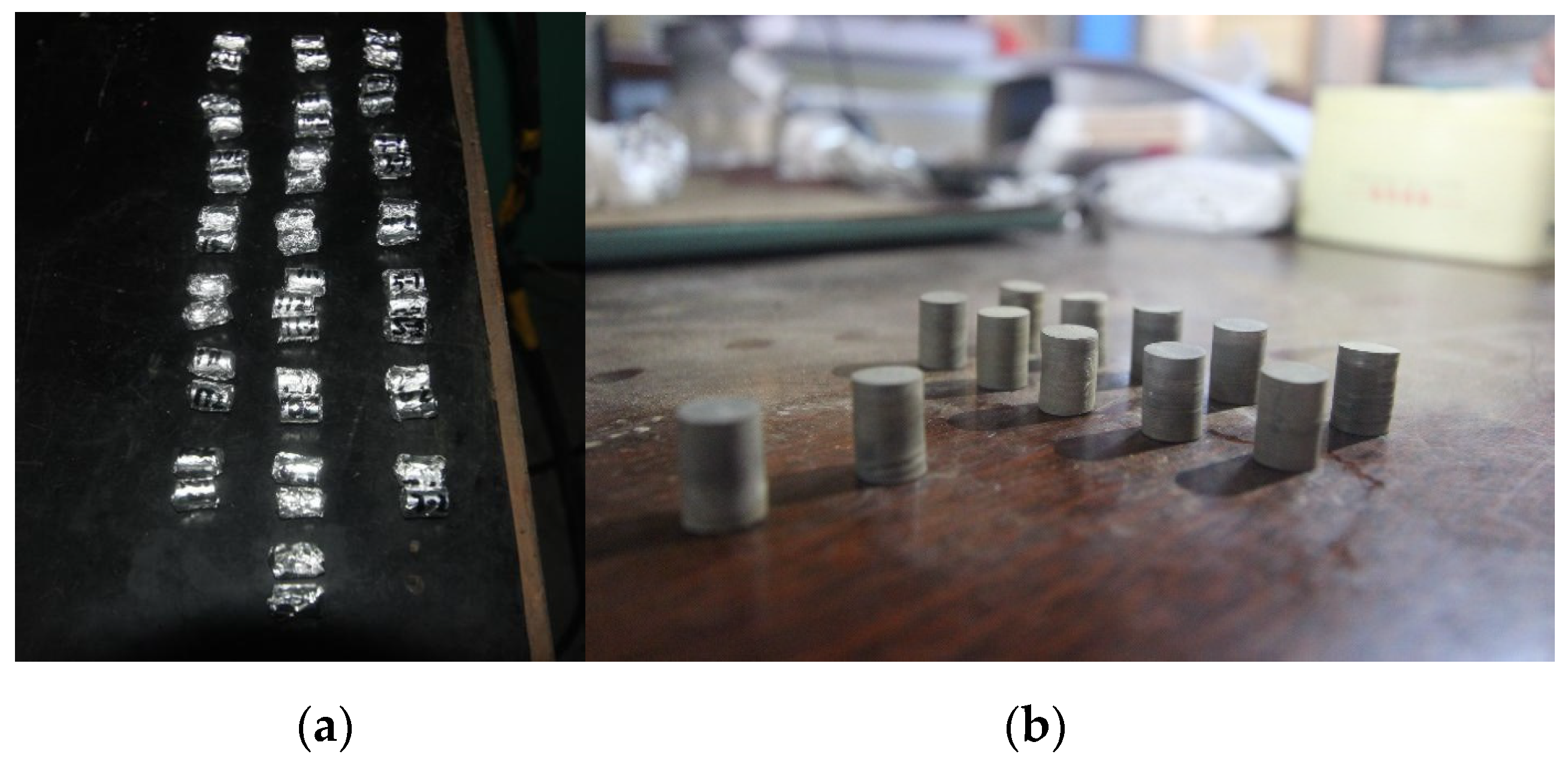
2.1. Sample Preparation and Pyrolysis

In this study, three large rectangular oil shale blocks were selected from Fushun, Liaoning province in China, which were immediately sealed with wax to avoid oxidation and were then brought to the laboratory. Cylindrical specimens with a diameter of 10 mm and a length of 13 mm were then obtained from these blocks by using a diamond core driller. All the obtained samples were carefully ground and polished, and the axial and radial directions were kept strictly perpendicular.
In this experiment a total of 32 samples, divided into two groups of 16 specimens corresponding to 16 pyrolysis temperature points, were adopted for the retorting and combustion test in a muffle furnace, shown in Figure 1. The target temperatures were set as follows: 20 °C (room temperature), 100 °C, 200 °C, 300 °C, 325 °C, 350 °C, 375 °C, 400 °C, 425 °C, 450 °C, 475 °C, 500 °C, 525 °C, 550 °C, 575 °C and 600 °C. Two samples were assigned to the raw oil shale. Another two samples were placed in the muffle furnace to be slowly heated up to 100 °C at a rate of 10 °C/min. This retorting temperature was maintained for 30 min to reach a sufficient heating duration period for kerogen pyrolysis to occur, and then the samples were naturally cooled to room temperature. The same procedure was repeated for the remaining samples until pyrolysis was completed.

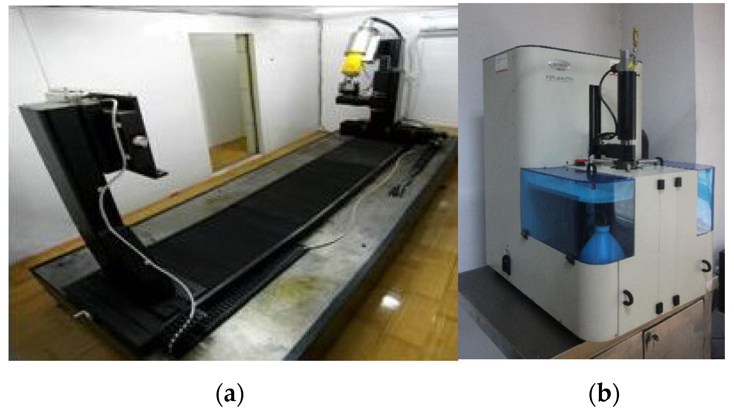
2.2. X-ray Micro Tomography for Fracture Distribution

Because of the existence of obvious stratification and the difference in the thermal expansion of multiphase particles, many cracks inside the oil shale appeared during the heating process. In this experiment, the X-ray Micro Tomography (µCT225kVFCB, shown in Figure 2a) was used to scan the internal structure inside the oil shale at different pyrolysis temperatures, and a series of grayscale images reflecting the internal microfine features were obtained [33,34,35]. According to the relationship between the ray intensity and material density, a clear scanned image was obtained in which white means high density particles and black represents low density material (even void spaces). The CT system employed in the XMT experiment has a highest magnification of 400 times, which corresponds to the ability to detect 0.5 μ m pores and cracks with a width of 1 μ m [36]. In this experiment, the sample images as shown in Figure 3 had a magnification of 37 times, which corresponded to the smallest crack at a width of 5 μ m . From the scanned images, the crack parameters were calculated and obtained by counting the pixel numbers.

2.3. Mercury Injection Porosimetry for Pore Structure

The next step of this study was the mercury injection test. A Quantachrome 33 instrument shown in Figure 2b was used to characterize the pore structure. The available pressure ranged from 20 to 33,000 PSI, which corresponded to pore sizes between 950 μ m and 6.4 nm. The test procedure consisted of two steps: a low-pressure stage and a high-pressure stage. The low-pressure range was from 0.2 to 50 PSI, and the high-pressure range was from 20 to 33,000 PSI [37]. Each sample was first placed in the low-pressure porosimeter, which was soon outgassed in a vacuum. Then, mercury was compressed to flow into the sample cell until the target pressure was reached and then the large-scale pore was accordingly monitored with increasing pressure. Subsequently, high-pressure porosimetry was performed in the other cabin by using the same specimen. Finally, the pore distribution data coupled to the low-pressure and high-pressure stages were obtained from the full experiment.

2.4. Implementation of 3D Simulation Model

In many fields, percolation theory is widely used to analyse disordered and random distributions, such as the spread of disease and high temperature superconductors [38,39]. The permeability transition of porous material belongs to these interesting fields worthy of great attention. Pyrolyzed oil shale should be considered a fracture-pore dual medium because of the new generation of pore space and fracture in thermal environment. The percolation probability variations of the fracture-pore dual medium simulation reflect the internal connectivity and permeability evolution process. Furthermore, percolation simulation can quantitatively determine the permeability of oil shale model at any pyrolysis temperatures and concretely indicate the transport property of oil shale after pyrolysis. Therefore, it is reasonable to build a fracture-pore dual model and estimate the permeability of oil shale at different temperatures by applying the percolation method.
In the following study, a simulation model was estimated based on the fracture-pore dual medium model, and then the percolation probability of pyrolyzed oil shale could be calculated. In the dual medium model, the solid skeleton and void spaces are the parts that together form the porous material, and the void spaces are made up of pores and fractures. The interconnectivity between randomly distributed pores and fractures results in connected void clusters. As we know, the effective penetration network among the model must be the maximum void cluster, which is known as the “percolation cluster”. The void grid number of the maximum cluster is calculated, and then the percolation probability is obtained.
Based on above principle, it was assumed that the oil shale model was a 3D cube divided uniformly into 100 × 100 × 100 unit grids. In the model, the grid was only solid particles or void space. First, based on the porosity data obtained from the mercury porosimetry test, pores were randomly distributed throughout the cube model. For the fractures, studies have shown that the relationship between fracture length and number can be very well expressed by the power exponential: N ( L ) = N 0 L D [40]. In this numerical simulation, the parameters ( N 0 , D ) were known from the XMT test and some calculations. Second, as the length L gradually varied, fractures of different scales were randomly distributed into the grids. Finally, a rule was defined in which a grid that was occupied twice owing to the pore and fracture random distributions, was only counted as one void grid, and a grid occupied once owing to the pore or fracture distribution was also counted as one void grid. Thus, a computer algorithm was programmed to search and count the void grid number in the maximum void cluster and the percolation probability was obtained.

3. Results and Discussion

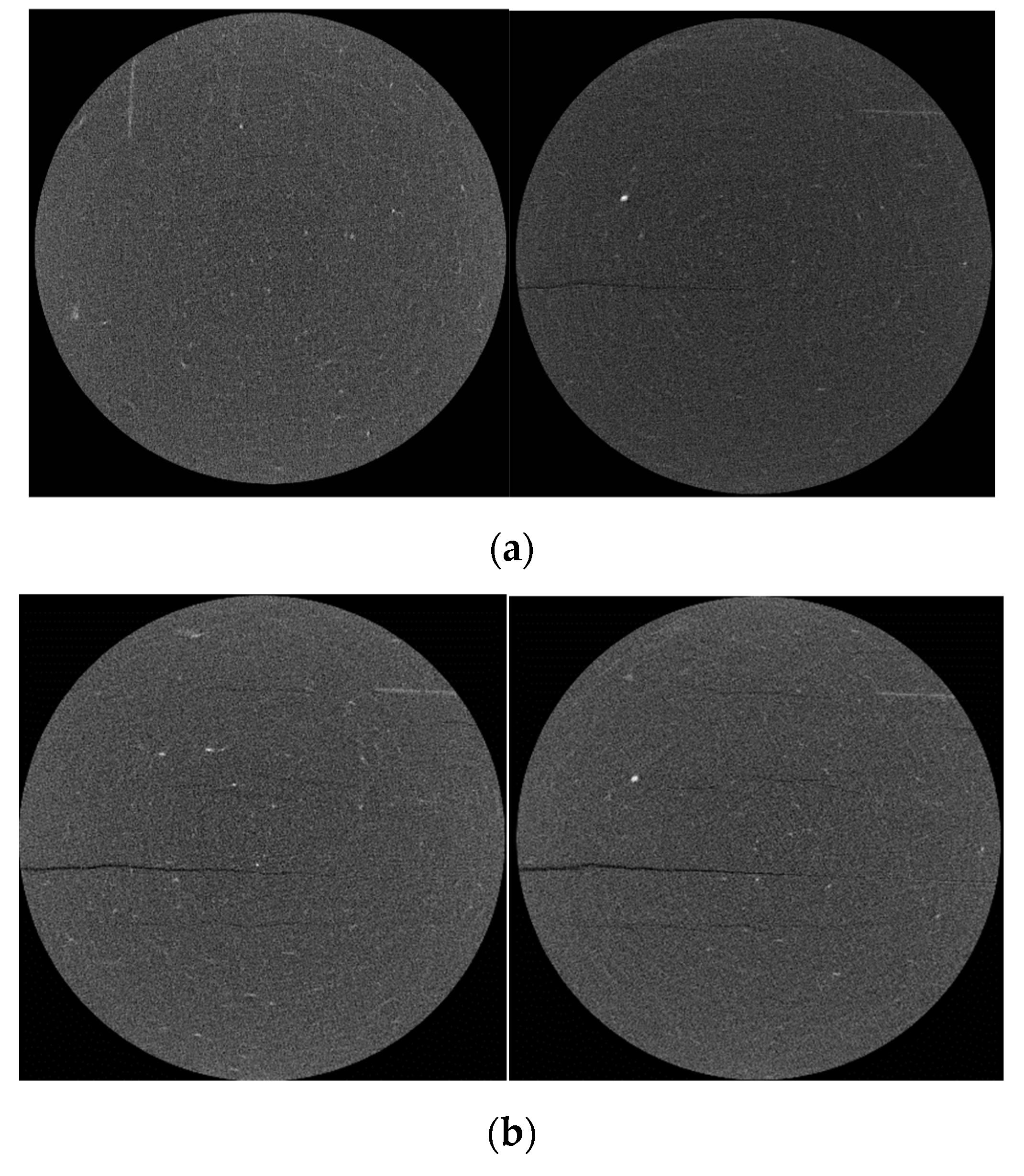
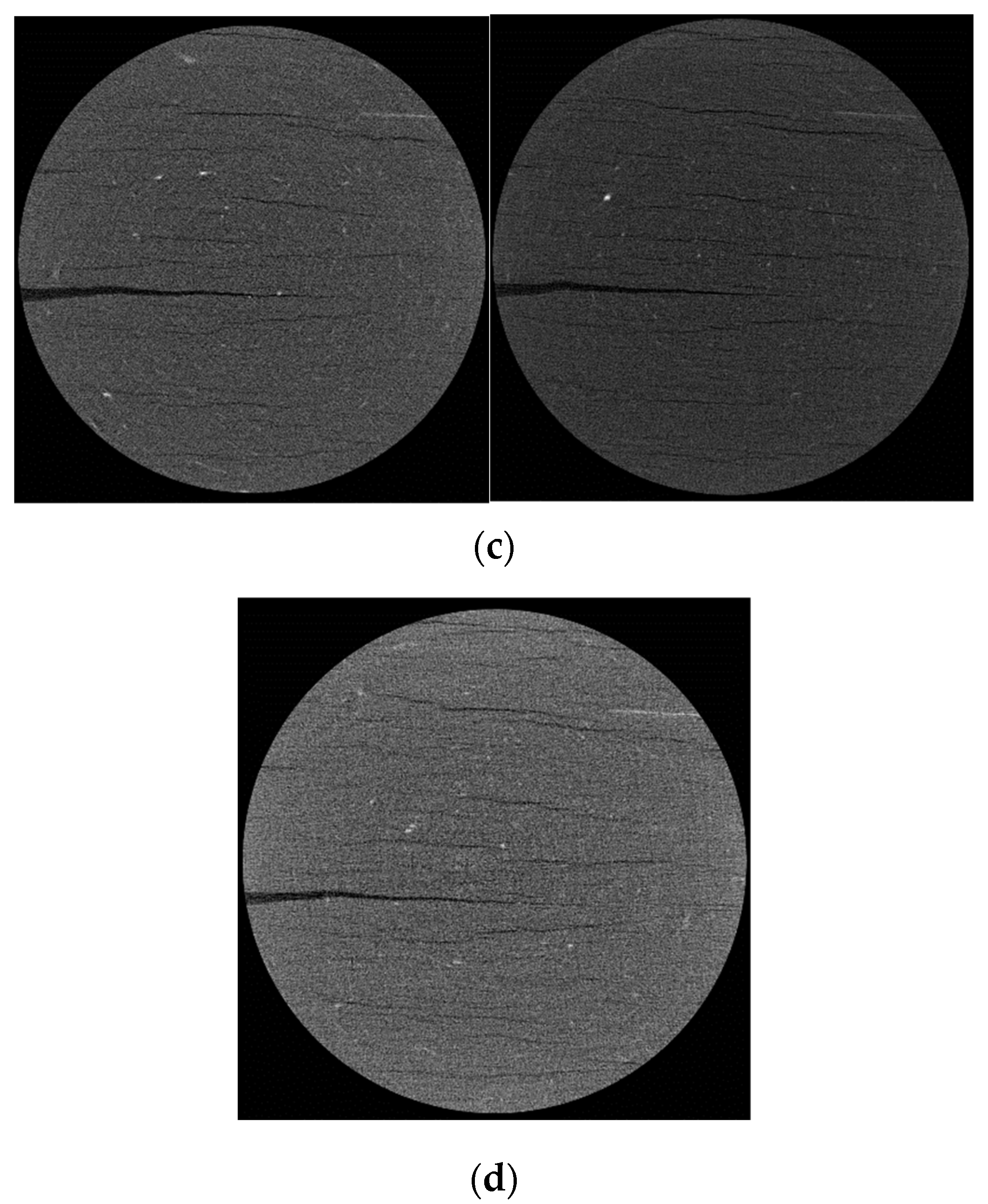
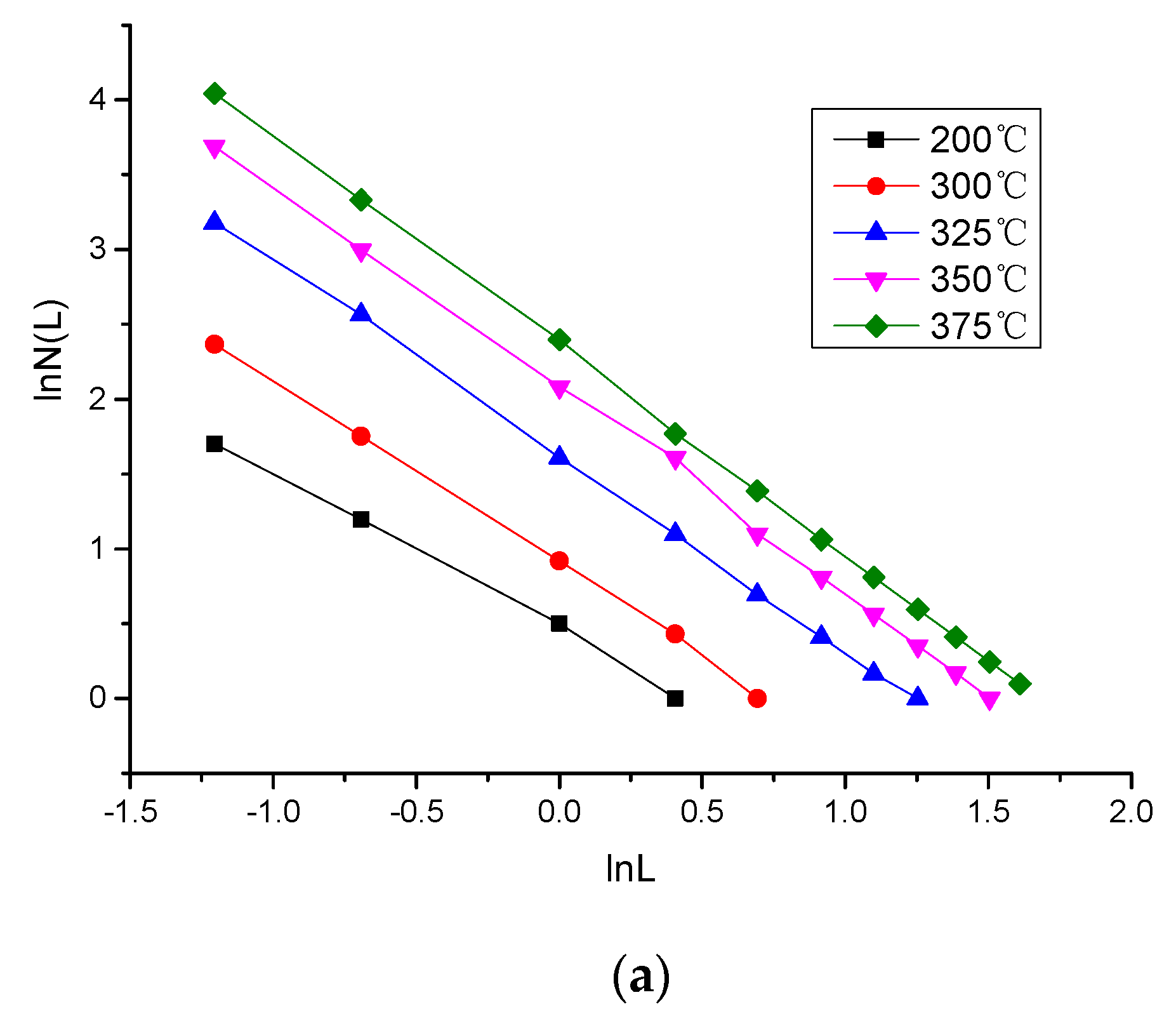
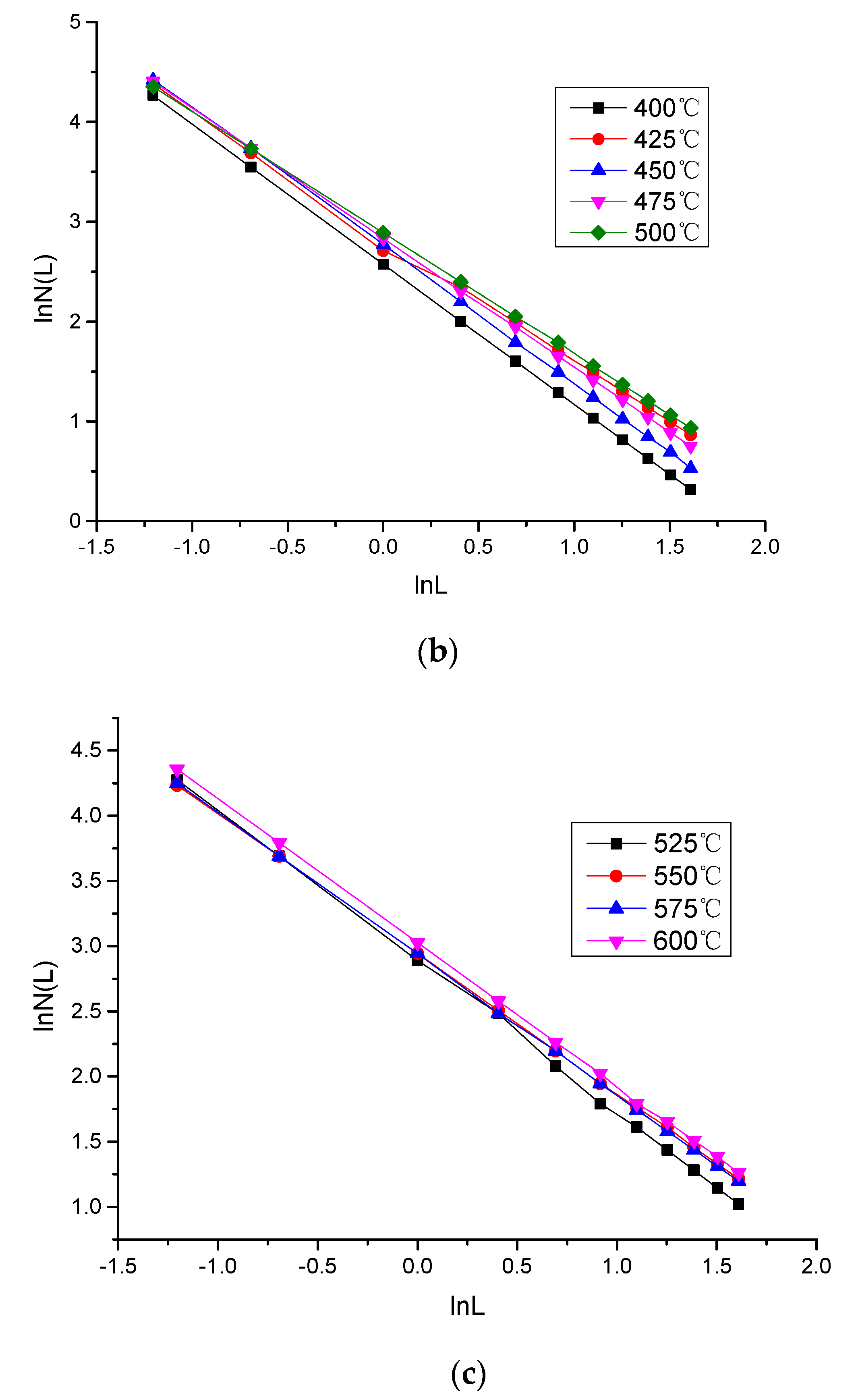
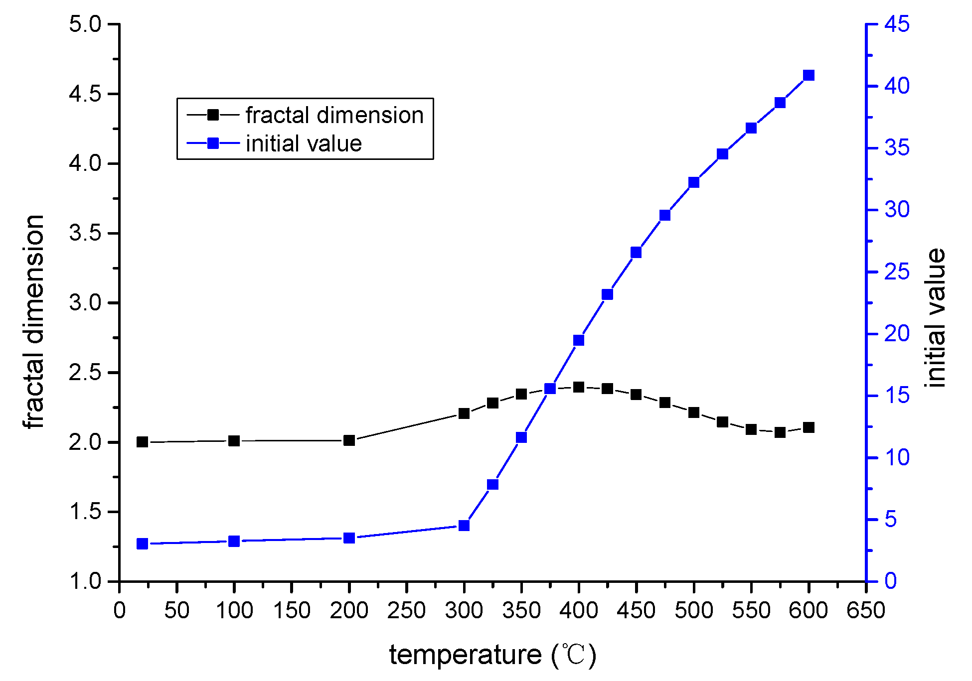
3.1. Fracture Distribution with Increasing Temperature

3.1.1. 2D Fracture Distribution

Unconstrained pyrolysis experimentation on the oil shale samples brought about many changes in the generation of cracks and played a key role in increasing permeability. The XMT technique clearly revealed the fracture distribution in the oil shale sample cross section. Typical oil shale CT images at 37× magnification under different retorting temperatures are illustrated in Figure 3. Figure 3a shows an image of a raw oil shale sample cross section, and Figure 3b–d shows cross-sectional images of oil shale samples heated to 100 °C, 200 °C, 300 °C, 400 °C, 500 °C and 600 °C.
As noted in Figure 3a, the raw oil shale particles are tightly cemented and basically epigranular, and the very few white spots (high-density minerals, possibly pyrite) that have higher density are distinct from the dark zone. Moreover, no cracks could be observed in the image. When it was heated to 100 °C, one slender crack clearly emerged in the central position of the core section and extended over more than half the length of the radius, indicating that the oil shale sample retained a relatively low degree of cementation in the central position. As the reaction pyrolysis continued and the temperature rose to 200 °C and 300 °C, thermal cracking became more evident, the existing one enlarged, and several parallel new cracks appeared on either side of it. When the temperature reached 400 °C, the existing cracks became much wider and longer, and many new cracks emerged noticeably in the section. It is believed that the difference in the thermodynamic properties of different mineral particles caused this expansion and fissuration. When the temperature reached 500 °C and 600 °C, a decrease of crack numbers occurred owing to the joining of adjacent cracks. Not many new extensive cracks were initiated, and the sample section configuration underwent fewer changes.
As previously noticed, thermal treatment affects the fracture development in the whole pyrolysis process. All fractures observed were basically parallel to the bedding plane, which demonstrates that the cementation of oil shale particles is greater than the cementation between laminae. The occurrence sequences of fractures implied that the central position in the sample cross-section seems likely to have a weaker cementation compared with the sides. Higher thermal temperature made the bedding planes with a stronger degree of cementation split on the sides of the sample section. Additionally, under different thermal conditions the fracture number varied significantly, and as the temperature increased the fractures grew larger and more numerous. The fracture numbers increased quite rapidly with increased temperatures over the lower range of temperatures, but this rate of increase decreased in the higher temperature range of processing.

3.1.2. 3D Fracture Distribution

To quantitatively analyse the variation characteristics of the crack number of oil shale samples at different pyrolysis temperatures, the crack parameter in the CT images of oil shale cross section was obtained as follows: the fracture number N ( L ) was counted, which is greater than or equal to the pre-set fracture length L ; then, the length scale L was subsequently changed and N ( L ) was counted again. The detailed results were plotted on the log-log plane in Figure 4. The curves demonstrated a good power function relationship between the fracture number and length. Based on power law and fractal geometry, we calculated the initial value, n L , and the 2D fractal dimension, D L . According to lots of statistical experimental data on the fractal parameter relationships between the 2D fracture trace and the 3D fracture surface, the values for D s and n s at all temperatures were obtained [41].
D S = D L + 1
n S = φ n L
In Equations (1) and (2), D s and D L represent the 3D and 2D fractal dimensions of the fracture number distribution, respectively; n s and n L represent the initial fractal values for 3D and 2D, respectively; and φ is the relational coefficient.
The variation of values for D s and n s is shown in Figure 5. The fractal dimension characterizes the complexity of the fracture number in different thermal conditions. Moreover, the initial fractal value was close to the proportion of large-scale fractures, and the larger the proportion of large-scale fractures, the larger the initial values. As depicted in Figure 5, from 200 °C to 600 °C, the fractal dimension increased first and then decreased with increasing temperature, thus reaching a maximum at approximately 400 °C, indicating that the fracture number variation of oil shale samples reached an inflection point at 400 °C. The initial value gradually increased with increasing temperature and reached an extreme value at 600 °C, indicating that the proportion of large-scale cracks in oil shale was increasing and reached the maximum at 600 °C. Several factors are responsible for these relationships. From 200 °C to 400 °C, due to the combined action of thermal effect and pyrolysis chemical reaction, the fracture evolution was mainly the generation of many new cracks and enlargement of existing fractures. The fracture morphology becomes increasingly complicated as temperature increases. Therefore, the fractal dimension and the initial value increase gradually with the increase of temperature. The temperature range of 400 °C to 600 °C was the dramatic development stage of thermal effect. The fracture evolution was mainly the mode of “expansion-lap-connection” between the existing fractures, which results in the decrease of the number of small-scale fractures and an increase in the number of large-scale fractures. The fracture morphology inside oil shale was maintained at a relatively stable state. Hence, the fractal dimension decreased with increasing temperature, and the initial value of fractal increased with increasing temperature.

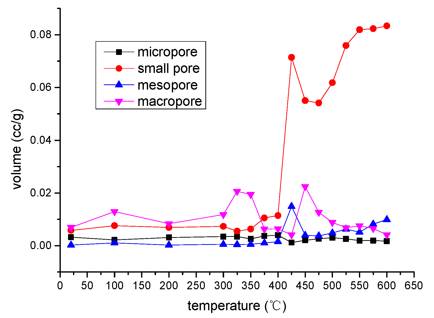
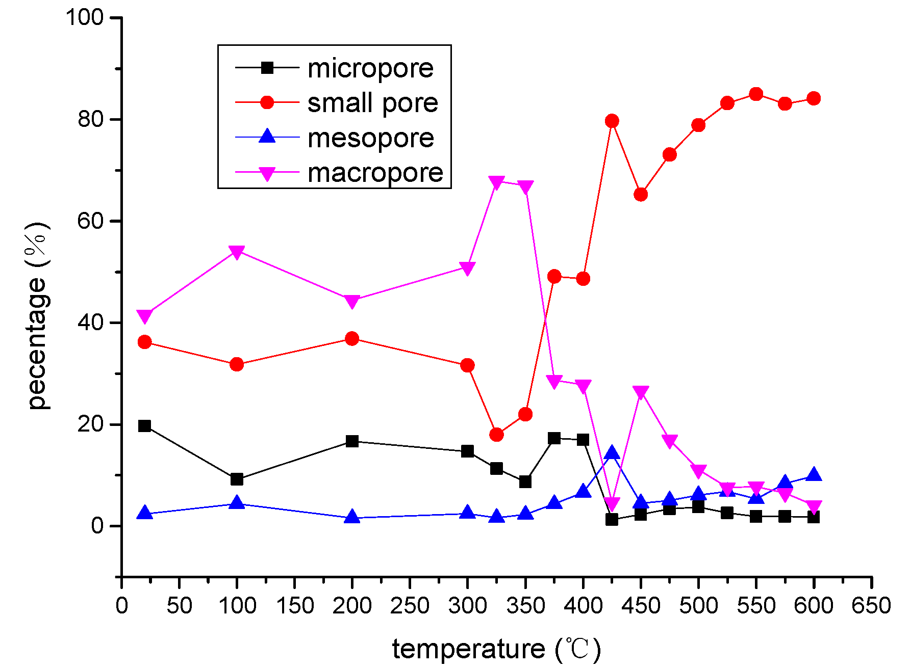
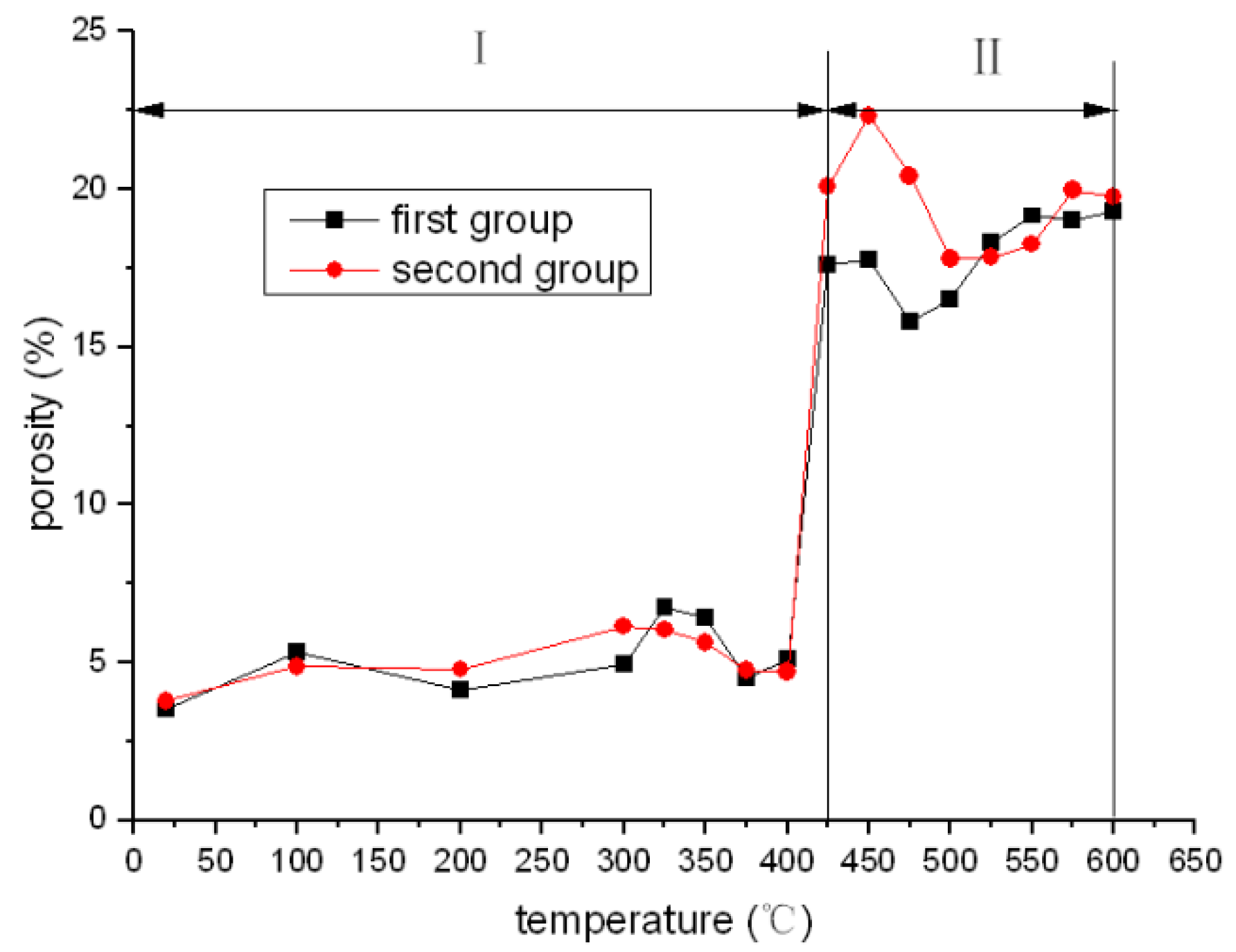
3.2. Pore Characteristic in the Pyrolysis Process

Thermal pyrolysis has a direct influence on the pore structures. The test of pyrolyzed oil shale samples with a mercury porosimeter acquires a better understanding of the change in the pore networks. In this section, the features of the pore structure evolution during pyrolysis were analysed by investigating the porosity and distribution of pore spaces. According to the work by Geng et al., four pore categories can be defined: macropores (>1000 nm), mesopores (100–1000 nm), small pores (10–100 nm), and micropores (<10 nm) [42]. Here, one group of data was chosen for analysis of the pore distribution. The pore volume and the proportions of different pore sizes in the full temperature zone are shown in Figure 5 and Figure 6.
The reaction processes at high temperature in oil shale play different roles on the effect of pore structure. Figure 6 shows that different pyrolysis stages resulted in large differences in pore spaces. At room temperature, the total pore volume of the specimen was 0.0161 cc/g, and at 400 °C it was 0.0233 cc/g, an increase of only 0.0072 cc/g, corresponding to a 45% increase. However, when the temperature rose to 425 °C, the pore volume sharply increased to 0.0916 cc/g, which was almost 6 and 4 times that of room temperature and 400 °C, respectively. Meanwhile the pore structure varied significantly with the temperature increase as seen from Figure 7. At room temperature, the proportions of macropores and small pores were almost 40%, and mesopores held the smallest part of the proportion. The micropore volume was approximately 0.003 cc/g and changed little as the temperature increased during the whole reaction process. However, a dramatic increase was observed in the small pore volume: when the temperature was lower than 425 °C the maximum volume was 0.0115 cc/g, but once it reached at 425 °C, the small pore volume increased sharply to 0.0715 cc/g, which was an increase of 0.06 cc/g or a 5-fold increase. In the whole pyrolysis process, the percentage of small pores grew from 36% at room temperature to 80% at 425 °C and 84% at 600 °C. It was obvious that the generation of new pore spaces was mainly due to an increase of numbers of small pores for the oil shale samples from the Fushun area during thermal treatment. Additionally, the reaction temperature zone occurred between 400 °C and 425 °C where most of the organic matter rapidly decomposed.
Figure 8 displays the porosity variation at different temperatures of the samples and shows that the whole porosity curve can be visibly divided into two stages. The temperature point of 425 °C, where there was a large growth in porosity, can be viewed as the boundary. In stage I, there was some slight fluctuations in porosity with the rise in temperature, which indicates no significant physical or chemical reactions occurred in the specimens. Only the dissociated water and some volatile substances inside the samples evaporated at this low temperature pyrolysis stage, the low volume of which did not contribute to a significant change of the porosity. Kang et al. 2017 obtained similar results when the retort temperature was below 200 °C for a thermogravimetric analysis of Fushun oil shale [43]. From room temperature to 400 °C, the porosity value fluctuated barely 5% and was almost the same as the porosity of the raw oil shale sample. In contrast, at the beginning of stage II, a sharp increase in porosity was observed from 400 °C to 425 °C. The value of the latter point was nearly three times that of stage I. These evident changes show that the pyrolysis environment at this temperature range provides sufficient heat to meet the energy threshold of the organic matter decomposition. The proper condition makes the organic matter decompose at such a narrow temperature range. At this point, many organic matter types were pyrolyzed and mixtures of hydrocarbon and gas separated out, leaving plenty of new pores. This caused the dramatic change of porosity that corresponded with the pore volume variation. Kang et al. also found a sharp fall in the weight of the Fushun oil shale sample from 350 °C to 480 °C [43]. The results of large-scale pilot test further verified this conclusion [44]. As the temperature continued to increase, a small porosity valley occurred in the range of 450–550 °C. This might be caused by the pore occupancy of some products or rock-solid matrix expansion, which needs to be further investigated.

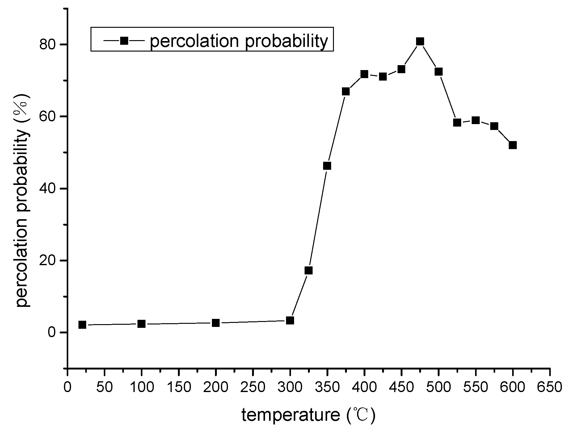
3.3. Percolation Calculation of the Fracture-Pore Dual Medium

Table 1 lists the percolation probability values at different pyrolysis temperatures for the single pore media and fracture-pore dual medium simulations. The percolation probability curve of the dual medium is shown in Figure 9. As seen in Table 1, for the single pore media model, during the pyrolysis process the grid number in the maximum cluster was less than 100, which means the connected clusters were confined to isolated areas or there were very few connected clusters, which led to no effective seepage channels. Therefore, the percolation probability was extremely low, which was far from reaching the theoretical threshold of 31.16%, indicating that the oil shale model only consisted of pores that do not have sufficient ability to establish effective percolation networks [45]. However, for the dual medium model, the amount of void grid in the maximum cluster was far greater than that of the single media model, by three orders of magnitude, under the same thermal conditions. As noted in Table 1, from room temperature to 300 °C, in the dual medium model, the grid quantity of the maximum cluster were quite few and the percolation probabilities were relatively low, which give a clear signal that the connected clusters still remained isolated from other void clusters and effective seepage channel had not yet formed. When the temperature reached 350 °C, the number of void grids in the maximum cluster grew to twice that of the previous temperature and the percolation probability subsequently increased to 46%, which exceeded the threshold of 31.16%. This theoretically means that the oil shale model was permeable. Meanwhile, it can be seen in Figure 6 that there was no new generation of pore spaces at the same temperature point. Apparently, the connected fracture network mainly drove the percolation transition of the oil shale model. As the temperature increased, as seen from Table 1, the percolation value continued to rise to the maximum value of 81% at the temperature of 475 °C. In addition, from 350 °C to 600 °C, the percolation probability was continuously higher than the threshold value, which means that effective flow channels had formed and the fuel products can flow out through the connected networks. By contrast, the percolation probability of the single pore media model was far below 1% in the whole temperature range. The limited growth of and discrete distribution of pore spaces resulted in the percolation behaviour of the single pore model. Accordingly, the seepage channel was primarily dependent on the connection of the fractures. The developed fractures had a more important effect on the formation of penetration networks and emigration of pyrolysis products.

4. Conclusions

In this work, a microscopic analytical technique and mercury injection porosimetry were used to study the mesoscopic structural evolution of oil shale samples after pyrolysis using several temperatures. Then the fracture-pore dual medium model was employed to use the percolation method to describe the permeability variation of pyrolyzed oil shale. From this study, some conclusions can be drawn.
Analysis from the mercury injection porosimetry showed that the samples under different retorting temperatures had significant variation in pore structure. Over the pyrolysis zone of 400 °C to 425 °C, most of the organic matter was released, generating a great number of small pores which directly affected the porosity and pore structure of samples. Meanwhile high temperature conditions had a significant effect on the characteristics of fracture distribution inside the samples. The fracture surface morphology and number varied with increasing temperature. The fractures were distributed parallel to the bedding plane and appeared first in the central position of the sample section, which had a weaker cementation, and then extended into the sides. Additionally, the variation in number of fractures was well expressed by fractal geometry. The mathematic calculations of the percolation probability comparison of the fracture-pore dual medium model and the single pore media model for oil shale demonstrate that fractures are a more important component of the formation of transfusion channels. This percolation simulation reveals that in the dual medium model, the percolation probability had already exceeded the threshold value by 350 °C, which means the effective penetration networks had formed.

Author Contributions

Conceptualization, Y.Z. and H.T.; methodology, H.T.; software, Z.K.; validation, Z.L., Z.K. and D.Y.; formal analysis, H.T.; investigation, Z.K.; resources, Y.Z.; data curation, H.T.; writing—original draft preparation, H.T.; writing—review and editing, H.T.; visualization, H.T.; supervision, K.W.; project administration, Y.Z.; funding acquisition, Y.Z. All authors have read and agreed to the published version of the manuscript.

Funding

This research was funded by the National Natural Science Foundation of China (No.11772213, No.51704206).

Institutional Review Board Statement

Not applicable.

Informed Consent Statement

Not applicable.

Data Availability Statement

Not applicable.

Acknowledgments

The authors thankfully acknowledge the Mining Institute Technology, Taiyuan University of Technology, for the provision of experimental equipment.

Conflicts of Interest

The authors declare no conflict of interest.

References

  1. Dyni, J.R. Geology and resources of some world oil-shale deposits. In Oil Shale Developments; U.S. Geological Survey: Reston, VA, USA, 2009; ISBN 9781607414759. [Google Scholar]
  2. Crawford, P.M.; Biglarbigi, K.; Dammer, A.R.; Knaus, E. Advances in world oil shale production technologies. In Proceedings of the SPE Annual Technical Conference and Exhibition, Denver, CO, USA, 21–24 September 2008. [Google Scholar]
  3. Kang, Z.; Zhao, Y.; Yang, D. Review of oil shale in situ conversion technology. Appl. Energy 2020, 69, 115121. [Google Scholar] [CrossRef]
  4. Schrodt, J.T.; Ocampo, A. Variations in the pore structure of oil shales during retorting and combustion. Fuel 1984, 63, 1523–1527. [Google Scholar] [CrossRef]
  5. Tiwari, P.; Deo, M.; Lin, C.L.; Miller, J.D. Characterization of oil shale pore structure before and after pyrolysis by using X-ray micro CT. Fuel 2013, 107, 547–554. [Google Scholar] [CrossRef]
  6. Zhao, J.; Yang, D.; Kang, Z.; Feng, Z. A micro-CT study of changes in the internal structure of Daqing and Yan’an oil shales at high temperatures. Oil Shale 2012, 29, 357–367. [Google Scholar] [CrossRef] [Green Version]
  7. Wang, L.; Yang, D.; Li, X.; Zhao, J.; Wang, G.; Zhao, Y. Macro and meso characteristics of in situ oil shale pyrolysis using superheated steam. Energies 2018, 11, 2297. [Google Scholar] [CrossRef] [Green Version]
  8. Saif, T.; Lin, Q.; Bijeljic, B.; Blunt, M.J. Microstructural imaging and characterization of oil shale before and after pyrolysis. Fuel 2017, 197, 562–574. [Google Scholar] [CrossRef]
  9. Saif, T.; Lin, Q.; Butcher, A.R.; Bijeljic, B.; Blunt, M.J. Multi-scale multi-dimensional microstructure imaging of oil shale pyrolysis using X-ray micro-tomography, automated ultra-high resolution SEM, MAPS Mineralogy and FIB-SEM. Appl. Energy 2017, 202, 628–647. [Google Scholar] [CrossRef]
  10. Kang, Z.Q.; Zhao, Y.S.; Meng, Q.R.; Yang, D.; Xi, B.P. Micro-CT experimental research of oil shale thermal cracking laws. Acta Geophys. Sin. 2009, 52, 842–848. [Google Scholar]
  11. Kang, Z.; Yang, D.; Zhao, Y.; Hu, Y. Thermal cracking and corresponding permeability of Fushun oil shale. Oil Shale 2011, 28, 273–283. [Google Scholar] [CrossRef] [Green Version]
  12. Priest, S.D. Determination of discontinuity size distributions from scanline data. Exp. Fluids 2004, 37, 347–368. [Google Scholar] [CrossRef]
  13. Song, J.J. Estimation of areal frequency and mean trace length of discontinuities observed in non-planar surfaces. Rock Mech. Rock Eng. 2006, 39, 131–146. [Google Scholar] [CrossRef]
  14. Song, J.J.; Lee, C.I. Estimation of joint length distribution using window sampling. Int. J. Rock Mech. Min. Sci. 2001, 38, 519–528. [Google Scholar] [CrossRef]
  15. Martyushev, D.A.; Yurikov, A. Evaluation of opening of fractures in the Logovskoye carbonate reservoir, Perm Krai, Russia. Pet. Res. 2021, 6, 137–143. [Google Scholar] [CrossRef]
  16. Zhukov, V.S.; Kuzmin, Y.O. Experimental evaluation of compressibility coefficients for fractures and intergranular pores of an oil and gas reservoir. J. Min. Inst. 2021, 251, 658–666. [Google Scholar] [CrossRef]
  17. Liu, C.; Zhang, L.; Li, Y.; Liu, F.; Martyushev, D.A.; Yang, Y. Effects of microfractures on permeability in carbonate rocks based on digital core technology. Adv. Geo-Energy Res. 2022, 6, 86–90. [Google Scholar] [CrossRef]
  18. Kruhl, J.H. Fractal-geometry techniques in the quantification of complex rock structures: A special view on scaling regimes, inhomogeneity and anisotropy. J. Struct. Geol. 2013, 46, 2–21. [Google Scholar] [CrossRef]
  19. Bagde, M.N.; Raina, A.K.; Chakraborty, A.K.; Jethwa, J.L. Rock mass characterization by fractal dimension. Eng. Geol. 2002, 63, 141–155. [Google Scholar] [CrossRef]
  20. Riley, P.; Murray, A.B.; Tikoff, B. Geometric scale invariance, genesis, and self-organization of polygonal fracture networks in granitic rocks. J. Struct. Geol. 2012, 42, 34–48. [Google Scholar] [CrossRef]
  21. Ghosh, A.; Daemen, J.J.K. Fractal characteristics of rock discontinuities. Eng. Geol. 1993, 34, 1–9. [Google Scholar] [CrossRef]
  22. Xie, H. Fractals in Rock Mechanics; CRC Press: Boca Raton, FL, USA, 2020. [Google Scholar]
  23. Andrade, J.S.; Street, D.A.; Shinohara, T.; Shibusa, Y.; Arai, Y. Percolation disorder in viscous and nonviscous flow through porous media. Phys. Rev. E 1995, 51, 5725. [Google Scholar] [CrossRef]
  24. Stanley, H.E.; Andrade, J.S.; Havlin, S.; Makse, H.A.; Suki, B. Percolation phenomena: A broad-brush introduction with some recent applications to porous media, liquid water, and city growth. Phys. A Stat. Mech. Appl. 1999, 266, 5–16. [Google Scholar] [CrossRef]
  25. Mészáros, C.; Farkas, I.; Bálint, Á. A new application of percolation theory for coupled transport phenomena through porous media. Math. Comput. Simul. 2001, 56, 395–404. [Google Scholar] [CrossRef]
  26. Mo, H.; Bai, M.; Lin, D.; Roegiers, J.C. Study of flow and transport in fracture network using percolation theory. Appl. Math. Model. 1998, 22. [Google Scholar] [CrossRef]
  27. Kimmich, R.; Klemm, A.; Weber, M.; Seymour, J.D. Flow, diffusion, dispersion, and thermal convection in percolation clusters: NMR experiments and numerical FEM/FVM simulations. MRS Online Proc. Libr. 2001, 651, 271. [Google Scholar] [CrossRef]
  28. Berkowitz, B. Analysis of fracture network connectivity using percolation theory. Math. Geol. 1995, 27, 467–483. [Google Scholar] [CrossRef]
  29. Sahimi, M. Non-linear and non-local transport processes in heterogeneous media: From long-range correlated percolation to fracture and materials breakdown. Phys. Rep. 1998, 306, 213–395. [Google Scholar] [CrossRef]
  30. Tsakiroglou, C.D.; Klint, K.E.S.; Nilsson, B.; Theodoropoulou, M.A.; Aggelopoulos, C.A. From aperture characterization to hydraulic properties of fractures. Geoderma 2012, 181–182. [Google Scholar] [CrossRef]
  31. Wettstein, S.J.; Wittel, F.K.; Arajo, N.A.M.; Lanyon, B.; Herrmann, H.J. From invasion percolation to flow in rock fracture networks. Phys. A Stat. Mech. Appl. 2012, 391, 264–277. [Google Scholar] [CrossRef] [Green Version]
  32. Zhao, Y.; Feng, Z.; Lv, Z.; Zhao, D.; Liang, W. Percolation laws of a fractal fracture-pore double medium. Fractals 2016, 24, 1650053. [Google Scholar] [CrossRef] [Green Version]
  33. Ponomarev, A.A.; Zavatsky, M.D.; Nurullina, T.S.; Kadyrov, M.A.; Galinsky, K.A.; Tugushev, O.A. Application of core x-ray microtomography in oilfield geology. Georesursy 2021, 23, 34–43. [Google Scholar] [CrossRef]
  34. Masihi, M.; Shams, R.; King, P.R. Pore level characterization of Micro-CT images using percolation theory. J. Pet. Sci. Eng. 2022, 211, 110113. [Google Scholar] [CrossRef]
  35. Wei, Z.; Sheng, J.J. Study of thermally-induced enhancement in nanopores, microcracks, porosity and permeability of rocks from different ultra-low permeability reservoirs. J. Pet. Sci. Eng. 2022, 209, 109896. [Google Scholar] [CrossRef]
  36. Zhao, Y.; Yang, D.; Liu, Z.; Feng, Z.; Liang, W. Problems of Evolving Porous Media and Dissolved Glauberite Micro-scopic Analysis by Micro-Computed Tomography: Evolving Porous Media (1). Transp. Porous Media 2015, 107, 365–385. [Google Scholar] [CrossRef]
  37. De Las Cuevas, C. Pore structure characterization in rock salt. Eng. Geol. 1997, 47, 17–30. [Google Scholar] [CrossRef]
  38. Mou, W.W.; Xu, X.L. Percolation simulation of the infection growth models. Wuli Xuebao/Acta Phys. Sin. 2006, 55, 2871–2876. [Google Scholar] [CrossRef]
  39. Specht, E.; Goyal, A.; Kroeger, D. 2D and 3D percolation in high-temperature superconductors. Phys. Rev. B Condens. Matter Mater. Phys. 1996, 53, 3585. [Google Scholar] [CrossRef]
  40. Zhao, Y.; Feng, Z.; Liang, W.; Yang, D.; Hu, Y.; Kang, T. Investigation of fractal distribution law for the trace number of random and grouped fractures in a geological mass. Eng. Geol. 2009, 109, 224–229. [Google Scholar] [CrossRef]
  41. Yangsheng, Z.; Zengchao, F.; Dong, Y.; Weiguo, L.; Zijun, F. Three-dimensional fractal distribution of the number of rock-mass fracture surfaces and its simulation technology. Comput. Geotech. 2015, 65, 136–146. [Google Scholar] [CrossRef]
  42. Geng, Y.; Liang, W.; Liu, J.; Cao, M.; Kang, Z. Evolution of Pore and Fracture Structure of Oil Shale under High Temperature and High Pressure. Energy Fuels 2017, 31, 10404–10413. [Google Scholar] [CrossRef]
  43. Kang, Z.; Zhao, J.; Yang, D.; Zhao, Y.; Hu, Y. Study of the evolution of micron-scale pore structure in oil shale at different temperatures. Oil Shale 2017, 34, 42–54. [Google Scholar] [CrossRef] [Green Version]
  44. Yang, D.; Wang, L.; Zhao, Y.; Kang, Z. Investigating pilot test of oil shale pyrolysis and oil and gas upgrading by water vapor injection. J. Pet. Sci. Eng. 2021, 196, 108101. [Google Scholar] [CrossRef]
  45. Jan, N.; Stauffer, D.; Aharony, A. An infinite number of effectively infinite clusters in critical percolation. J. Stat. Phys. 1998, 92, 325–330. [Google Scholar] [CrossRef]
Figure 1. Oil shale samples: (a) Oil samples prepared for retorting muffle furnace; (b) Raw oil shales.
Energies 15 03572 g001
Figure 2. Experimental equipment: (a) X-ray Micro-Tomography system (model: µCT225kVFCB) from Taiyuan University of Technology; (b) Quantachrome 33 from Quantachrome Instruments.
Energies 15 03572 g002
Figure 3. Fracture distribution CT images at different temperatures: (a) Sample with a temperature of 20 °C on the left side and 100 °C on the right side; (b) Sample with a temperature of 200 °C on the left side and 300 °C on the right side; (c) Sample with a temperature of 400 °C on the left side and 500 °C on the right side; (d) Sample with a temperature of 600 °C.
Energies 15 03572 g003aEnergies 15 03572 g003b
Figure 4. The correlation between lnN(L) and lnL at different temperatures: (a) The logarithmic relationship between the fracture number and length at temperatures of 200 °C, 300 °C, 325 °C, 350 °C, 375 °C; (b) The logarithmic relationship between the fracture number and length at temperatures of 400 °C, 425 °C, 450 °C, 475 °C, 500 °C; (c) The logarithmic relationship between the fracture number and length at temperatures of 525 °C, 550 °C, 575 °C, 600 °C.
Energies 15 03572 g004aEnergies 15 03572 g004b
Figure 5. The correlation between fractal dimension, initial value, and temperature of the first group samples.
Energies 15 03572 g005
Figure 6. Pore volume of different size versus temperature of the first group samples.
Energies 15 03572 g006
Figure 7. The percentage of different groups versus temperature of the first group samples.
Energies 15 03572 g007
Figure 8. The sample porosity versus temperature of the two group samples: I: low porosity stage before pyrolysis; II: high porosity stage after pyrolysis.
Energies 15 03572 g008
Figure 9. Percolation probability of the double medium versus temperature of the first group samples.
Energies 15 03572 g009
Table 1. The percolation probability of different temperature.
Temperature (°C)Single Pore MediaDual Fracture-Pore Medium
Void Grid NumberPercolation Probability (%)Void Grid NumberPercolation Probability (%)
2070.000721,3512.14
100100.00123,5262.35
20080.000826,1362.61
30090.000933,2883.33
32590.000917,162517.16
35090.0009462,65746.27
37580.0008669,83566.98
40080.0008717,38271.74
425570.0057710,95371.10
450700.007731,32473.13
475510.0051803,84380.84
500490.0049724,97572.50
525480.0048582,76058.28
550710.0071589,30158.93
575700.007573,12657.31
600530.0053520,15852.02
Publisher’s Note: MDPI stays neutral with regard to jurisdictional claims in published maps and institutional affiliations.

