Article

The Influence of the Substrate and External Magnetic Field Orientation on FeNi Film Growth

1
Faculty of Electrical Engineering, Bialystok University of Technology, Wiejska 45D, 15-351 Białystok, Poland
2
Faculty of Chemistry, University of Bialystok, Ciołkowskiego 1K, 15-245 Białystok, Poland
*
Author to whom correspondence should be addressed.
Energies 2022, 15(10), 3520; https://doi.org/10.3390/en15103520
Submission received: 4 March 2022 / Revised: 5 May 2022 / Accepted: 9 May 2022 / Published: 11 May 2022
(This article belongs to the Section F: Electrical Engineering)

Abstract

:
The magnetic field-assisted electrodeposition of iron–nickel thin films on different substrates (aluminum, silver, and brass) was investigated. The process was performed galvanostatically in a sulfate solution. The same chemical and electrical conditions were applied for each sample growth, but the time restrictions and the external magnetic field orientation were changeable. The obtained results show a variation of surface morphology and composition dependence on the selected surfaces as a consequence of the presence and orientation of the external magnetic field. We discussed that the FeNi crystal structure depends on the film thickness. The results show the reduction of the film thickness after the external magnetic field application—a decrease of deposition rate.The FeNi alloy’s morphology, composition, and magnetic properties were investigated by scanning electron microscopy (SEM), X-ray diffraction, energy dispersive X-ray spectroscopy (EDX), and Mössbauer spectroscopy (MS).

1. Introduction

Investigations into FeNi alloys with various iron to nickel ratios have been the purpose of many studies (the Earth’s core consists of FeNi alloys) [1]. A number of methodologies are employed in the formation of the best quality thin films with high adhesion, high deposition rate, low roughness, and improved uniformity [2]. Electrodeposition of the two metals often does not result in an alloy, whose composition is a direct reflection of the solution content. This phenomenon is known as “anomalous co-deposition” [3,4,5]. All film properties, such as magnetic, mechanical, corrosion, and electric, are affected by the quality of the electrodeposited films—roughness, grain size, alloy composition, etc. [5,6]. Therefore, it is important to investigate the effect of the substrate influence on deposition. The crystal structure of the substrate influences the formation of nuclei (nucleation regime) and their growth [3,7,8]. Adhesion of the thin films on different substrates is the mechanism that was the aim of a number of studies [7,9,10]. There are scientific studies that confirm the preferences of the crystal structure of the deposited layer which repeatedly mimics the structure of the substrate [11]. In addition, the FeNi system behavior depends on a variety of experimental parameters (and their mutual interactions) such as ion concentration in solution, pH, deposition potential and current density value, and the presence of additives [12,13,14]. Parallel to electrochemical reactions, magnetic field forces are acting on the electrolyte [14,15]. The magnetohydrodynamic effect (MHD) is the result of the interaction with the external magnetic field (EMF) and electrochemical environment which reduces diffusion layer thickness and thus enhances mass transport [14]. The scientists concluded that parallel (II) arrangement of EMF lines and the electrode surface results in two-dimensional growth and a smoother deposit. The perpendicular (I_) orientation causes a rougher growth. Two kinds of nucleation were distinguished: instantaneous and progressive. In the case of instantaneous, all the nuclei are of the same age and grow at the same rate. The possibility of an effective decrease of the nucleation rate caused by irreversible processes near the boundary of the growing nucleus characterizes the progressive nucleation [15,16].
Among many excellent magnetic properties of FeNi alloys, the following can be especially distinguished: high magnetic resistivity, low magnetostriction, high permeability, giant magnetoimpedance (GMI), high magnetic saturation, and low coercivity. This has led to a wide range of applications of their alloys in modern materials [7,12,13,17]. The applied substrates could influence the properties of the obtained layers: their hardness/strength, ductility/toughness, density, electrical resistivity, elastic modulus, corrosion, specific heat, etc. [7]. In reference to the above, the giant magnetoresistance effect (GMR), which is based on the magnetization of the ferromagnetic layers, has been known for thirty years. Nowadays, artificially layered magnetic structures play a very important role in science and technology: space research, military applications (power electronics, actuators, current transformers, computation modules, and assemblies), security systems, high-density magnetic memory (nonvolatile memory devices, heads for magnetic data storage), nondestructive testing (magnetic tunnel junctions sensors), navigation (passive and wireless magnetic sensors), geology, and medicine (magnetic biosensors) [18,19,20,21,22,23,24,25]. Scientists use undercoat layers atop the plastic substrate to increase and control the soft magnetic properties of the films which are measured as a function of undercoat, spacer material, or the number of layer pairs. Flexible architectures are applied to electromagnetic-interference (EMI) reflectors, EMI absorbers, and identification markers which could be integrated into stretchable electronic systems or smart biomedical systems [24,25].
In our study, Mössbauer spectroscopy (MS) was used to gain a better understanding of the magnetic state of the alloy during the formation of the deposit [26,27]. A comprehension of the deposition process and the factors affecting it allows more accurate control over the electrochemical co-deposition. Substrate (chemical composition, oxidation ability, or crystal structure) and external magnetic field (its presence and spatial orientation) affects film composition and growth. The influence of material composition and its geometry on the magnetic properties are still arbitrarily reported and studied by scientists. The concept of new materials fabrication is directly linked to investigations involving the details of their production. Modern engineering processes are used for advanced surface finishing.
The aim of this paper was to discuss the morphological and crystallographic aspects of the deposited film on selected substrates in the presence of different spatially arranged external magnetic fields (EMF) on the basis of the experimental results.

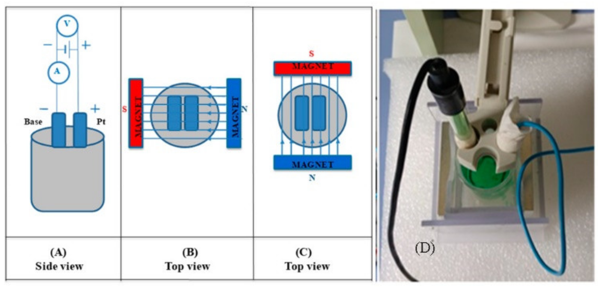
2. Materials and Methods

To study the electrodeposition of FeNi layers on Ag, Al, and brass plates, a working electrode with dimensions 10 mm × 20 mm × 0.25 mm (width × height × thickness) made from selected materials was used. All chemicals had p.a. purity and were purchased from Poland POCH Polish Chemicals (Gliwice, Poland): FeSO4·7H2O, NiSO4·7H2O, boric acid, perchloric acid, and ethanol. The pH of the electrolyte was measured by using Thermo Scientific Orion Star: Dual Star pH/ISE Benchtop Meter. Before electrodeposition, the value of pH was 2.52, and after the experiment, it decreased to 2.03.It confirms the electrolysis process in which on the anode H2O decomposes to H+ and O2.As a counter electrode, a standard platinum plate(width—6 mm × height—5 mm×thickness—0.5 mm) was applied. The electrolyte did not contain any additives (levelers, brighteners) except salts of Fe and Ni elements. For each process, the single-chambered, cylindrical glass cell with a diameter of 45 mm was filled with 20 mL of electrolyte. The distance between the vertically positioned anode and cathode was kept constant—20 mm. The deposition vessel had a space symmetrically placed between the external magnetic field source (EMF, IBS Magnet, Berlin, Germany)—two factory-made NdFeB permanent magnet plates (IBS Magnet, Berlin, Germany) of remanence of about 1 T(manufacturer data Br = 1.186 T). The orientation of the external magnetic field direction during the deposition process was out- or in-plane with respect to substrate plane orientation (Figure 1).The distance between the used magnets (width—75 mm × height—50 mm × thickness—10 mm) was fixed to be 55 mm. The permanent magnets were magnetized in the direction normal to the largest magnet face (75 mm × 50 mm) and B was oriented horizontally in both cases (II and I_). The magnetization vectors of both magnets were oriented antiparallel (II and I_). The gauge FH51 (Magnet-Physiks, Indianapolis, IN, USA) was used to measure and determine the distribution of the magnetic field among the largest magnet faces (sphere of electrodeposition). The magnetic field was nonuniform (except at the very center of the magnet), and its strength varied according to the distance from the magnet and ranged from 80 mT to 200 mT (with an accuracy of ±2%). All experiments were conducted at a temperature of 20–22 °C. The electrodeposition was performed galvanostatically (Direct Current mode—current density: 50.0 mA/cm2) using a potentiostat/galvanostat instrument (Matrix MPS-7163, MATRIX). A schematic presentation of the set-up is depicted in Figure 1. The thickness of the films was the average value of the cross-sectional measurements of the sample. The surface morphology and thickness of the films was investigated using a scanning electron microscope (SEM, INSPEC 60 from FEI, FEI Company, Hilsboro, OR, USA) where deposited film was placed by carbon tape on the SEM microscopic table. An energy dispersive X-ray spectrometer integrated with the SEM was used to provide information on alloy composition. An X-ray Diffractometer with a microfocus Mo Kα radiation source (λ = 0.713067 Å) was applied for film crystal structure characterization. For this measurement, part of the film was placed on a nylon loop glued by highly viscous oil and fixed on the tip compatible with the diffractometer goniometer.An individuallyconstructed Mössbauer Spectrometer (MS) was used to study the magnetic properties of the resultant FeNi alloys. [28,29]. There, deposited film was directly placed in the sample holder suitable for MS spectrometer where the γ-ray was perpendicular to the film plane.

FeNi Layers Deposition

Each substrate was electrochemically polished and activated by immersion into a mixture of 70%perchloric acid and 96%ethanol in a volume ratio of 25:75. The polishing process was carried out in the above solution cooled to 1°C with a current of 150 mA. FeNi layers were galvanostatically electrodeposited with the same current density value—50.0 mA/cm2. The time range changes between samples followed 3600, 2700, 1800, 900, and 450 s. For the experiments, a solution with a mixture of Ni and Fe sulfates (15% FeSO4·7H2O, 30% NiSO4·7H2O, 0.4% H3BO3) was used and the molar ratio between Ni:Fe ions was 2:1. To ensure the presence of an external magnetic field (EMF) at the sample position, the specially designed set-up was used for layers deposition. The source of the EMF was a set of two permanent magnets placed outside the electrodes (Figure 1). The magnetic field lines were arranged parallel (II) or perpendicular (I_) to the surface of the substrate.

3. Results and Discussion

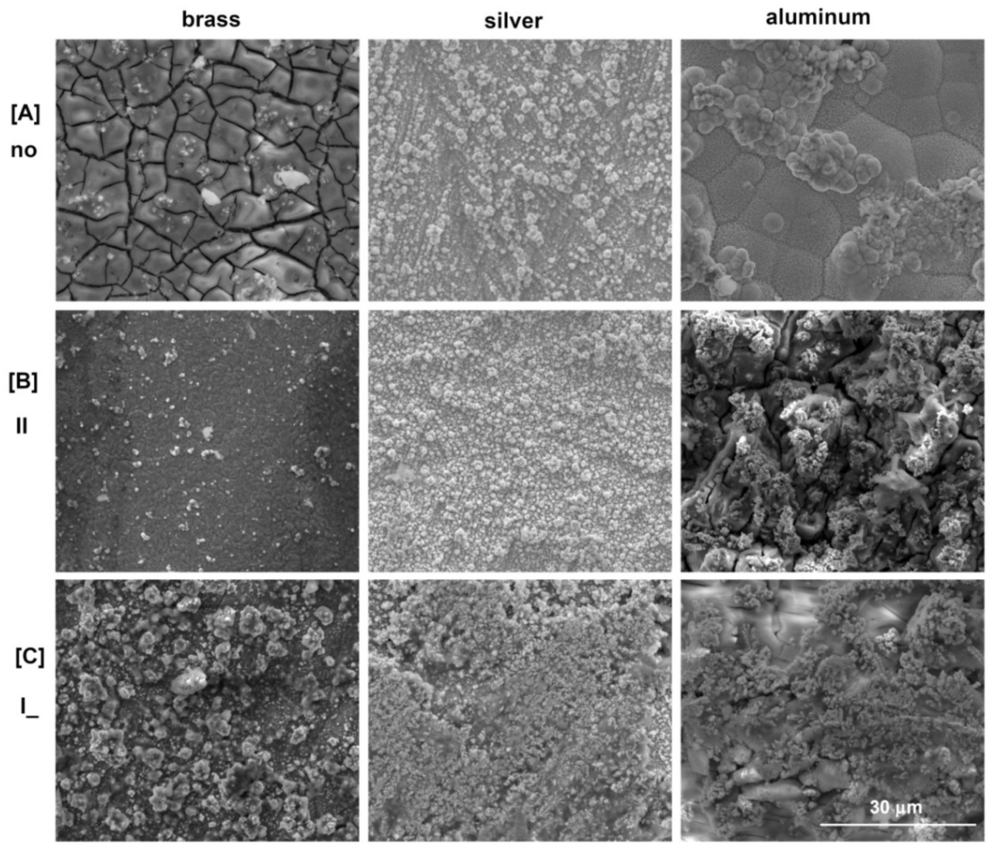
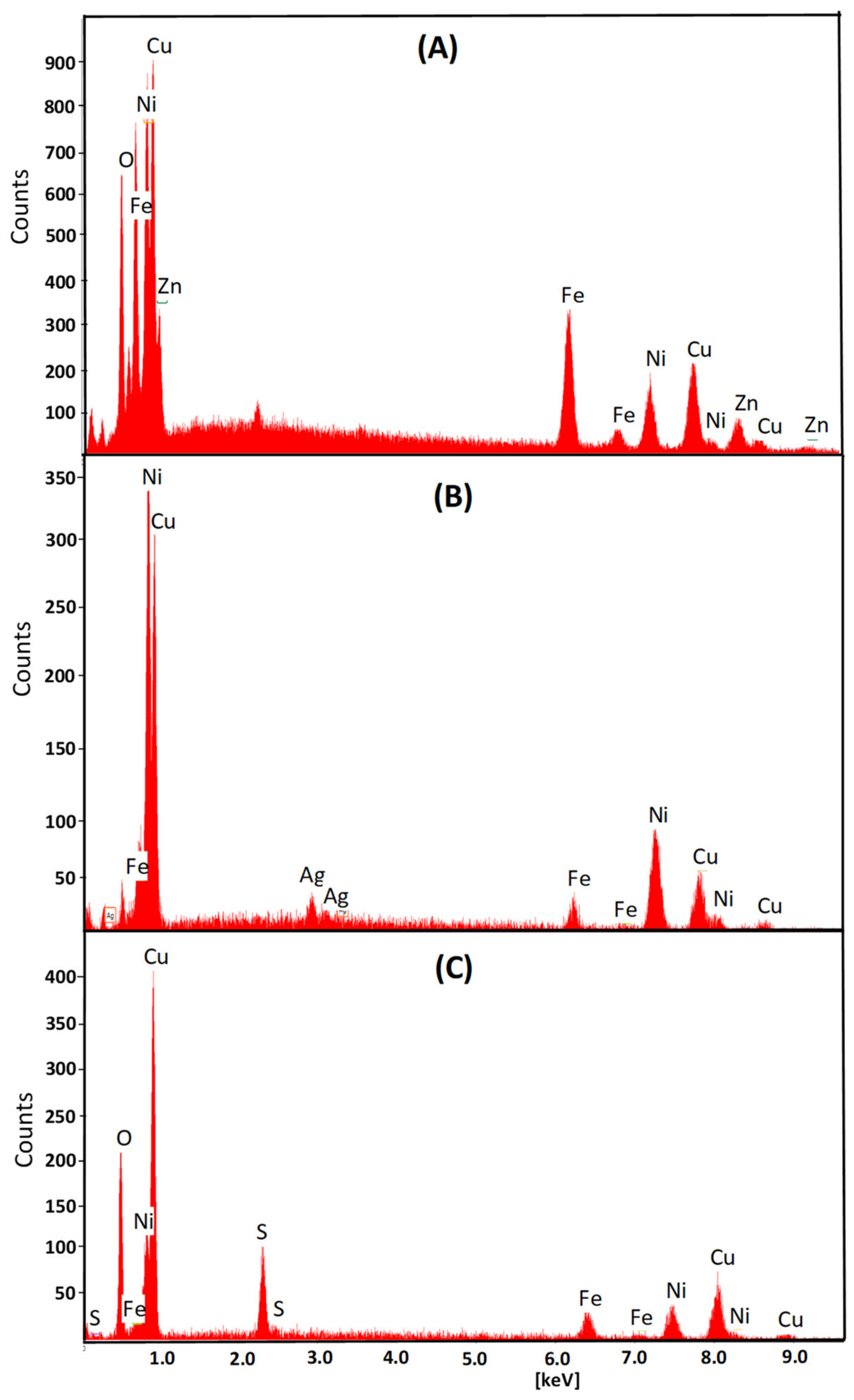
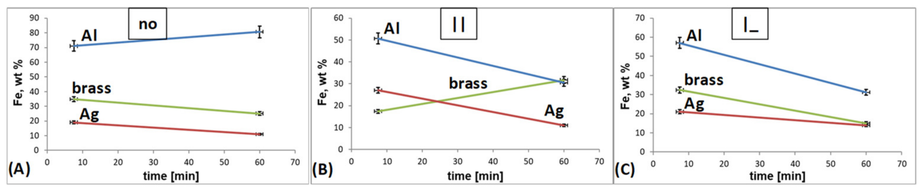
3.1. Scanning Electron Microscopy (SEM)

Prior to any other characterization of the FeNi film, its morphology and composition was investigated, respectively, by SEM and EDX (Figure 2 and Figure 3).
The images collected in Figure 2 show the surface morphology of the obtained FeNi films growing on the different substrates and in variable field conditions. It highlights the clear impact of not only the substrate composition but also the presence of an external magnetic field during the electrodeposition process. The strong effect of the magnetic field presence and its orientation on both mechanisms, nucleation and growth, is indisputable. Mutual competitionbetween the number of nucleation centersformed and the subsequentgrowth of existing onesvarieddepending on the presenceorabsence of anexternalmagnetic field, whichwasreflected in the roughness of the film. The film deposited on the brass substrate without the influence of the external magnetic field showed randomly distributed cracks on a relatively smooth surface. This was most probably the result of the formation of compounds with a hydroxyl group and the final effect of liberating hydrogen atoms from the surface—boric acid allows the incorporation of Fe(OH)+ on the surface [30,31,32]. The electrodeposition in the parallel oriented EMF to the substrate plane caused a reduction of the cracks and smoothening of the surface, while the perpendicular imposed magnetic field made the point nucleation more instantaneous. This kind of effect was characterized by the high growth rate of the new phase, and a small number of formed active nucleation sites significantly increased the unevenness of the surface of the obtained alloy. In the case of the deposition of FeNi films on a silver substrate without EMF assistance, the processes of nucleation and growth occurred instantaneously [33]. A constant number of nuclei grew on the substrate without the formation of new nuclei and therefore the surface morphology was rougher. The use of an external magnetic field led to an increase in mass transport to many more nucleation centers. It caused an increase in the uniformity of the FeNi layer distribution and increased its value for later industrial applications. The perpendicular setting of the EMF caused microvortices due to the micro MHD effect resulting in a larger number of nucleation centers. The local Lorenz forces acted around the growing nuclei. The nucleation fluctuations caused stronger vortices which suppressed the growth of the nuclei and resulted in the flatter surface morphology. The same effect was visible when the layer obtained on the aluminum substrate was also in the perpendicular EMF. The parallel setting of the external magnetic field caused a high growth rate (high number of grains) and rougher surface morphology. In the case without EMF application, the film was characterized by nodular particles with some flattened areas distributed over the whole surface [32,34]. The quantitative examination of the deposited film composition was performed by an EDX. Example spectra are in Figure 3.The obtained results of EDX analysis are shown in series in Figure 4.
Figure 4 shows a correlation between the used substrates and the time influence on the film composition (the changes of Fe content in FeNi alloys versus time of deposition, according to the EDX data). In the case of the deposition without the presence of EMF, an increase in the iron content with time is observed in the case of the aluminium substrate, while the decrease is obvious for the brass and silver substrates. The relationship between the composition of the alloy (iron content) and the used substrate characteristic is clear. This means that an increase in the iron content is observed for a paramagnetic substrate (Al) and its decrease in diamagnetic substrates (brass, Ag) when deposition takes place without external magnetic field presence. In the film deposited on the diamagnetic substrate (silver), the application of the EMF does not affect its composition. The composition of the alloy when EMF is applied differs for brass. For no EMF, the trend of time dependence is decreasing. After applying the perpendicular oriented external magnetic field, this tendency is present, but the rate of changes is more rapid. With the switching to parallel configuration modulation of the composition reverse and the Fe content increases with time. In the case of electrodeposition of some film on the aluminum substrate, the time dependence of the composition changes to the opposite when influenced by both settings of the EMF in comparison to no EMF. According to electromagnetic field theory, the paramagnetic substrate (aluminum) increases the magnetic field effect. Consequently, by acting contrary to the external magnetic field (EMF), the diamagnetic substrates (silver, brass) weaken this effect. Based on that, changes in the iron content of the resulting alloys are visible. The MHD theory deals with the weakening of the so-called “anomalous deposition” (the elimination of the deposition of a less noble metal) in the case of electrodeposition in an external magnetic field. This precisely reflects the decrease in the percentage of iron in the alloy on an aluminum substrate (paramagnet) after the application of EMF. In the case of alloys on silver and brass substrates (diamagnets), the above effect is not observable. The error bars included in Figure 4 have values similar to each other in all presented cases and do not affect the course of the characteristics.
Changes in the EMF appearance and its location (perpendicular and parallel) lead to modifications of the film’s composition (Figure 5). A decrease (brass, silver) or an increase (aluminum) of Fe content is observed without magnetic field assistance. In the case of Al, the inversion of the iron content takes place after the magnetic field application, regardless of perpendicular or parallel orientation. The anomalous co-deposition, characterized by a higher content of a less noble metal in the deposit than in the electrolyte, changes and disappears under the influence of an external magnetic field (parallel and perpendicular). The use of EMF reduces the percentage of iron in the alloy to the value resulting from the Ni:Fe ions ratio in the electrolyte. There were no visible changes in the iron content in the alloy film obtained on the silver substrate in comparison to the one on the aluminum substrate. After the application of a brass substrate, the iron percentage changes in another way than it has for the Al substrate. Composition changes are the most noticeable in the case of an external magnetic field arranged perpendicularly to the electrode surface. Both diamagnetic substrates (silver, brass) had a similar effect on the resulting FeNi layer. The diamagnetic nature of the substrates on which the layer (FeNi) is deposited results in a weak reaction or no reaction (morphology, composition) to the external magnetic field applied. These results are clearly shown in Figure 5 and are in agreement with the published data [9,17,35]. The choice of substrate has an impact on the average film thickness. From Figure 5, it is clear that the thinnest FeNi layer was obtained on the Ag substrate. The results also reflect an influence of the EMF arrangement on the film’s thickness. Based on this study, a clear correlation between the crystal structure and the external magnetic field presence, its orientation, and distribution was demonstrated. In the case of all considered substrates, the greatest thickness of the FeNi layer was obtained in the case of deposition without the presence of an external magnetic field and the thickness decreased after the application of the EMF regardless its orientation (Figure 5).

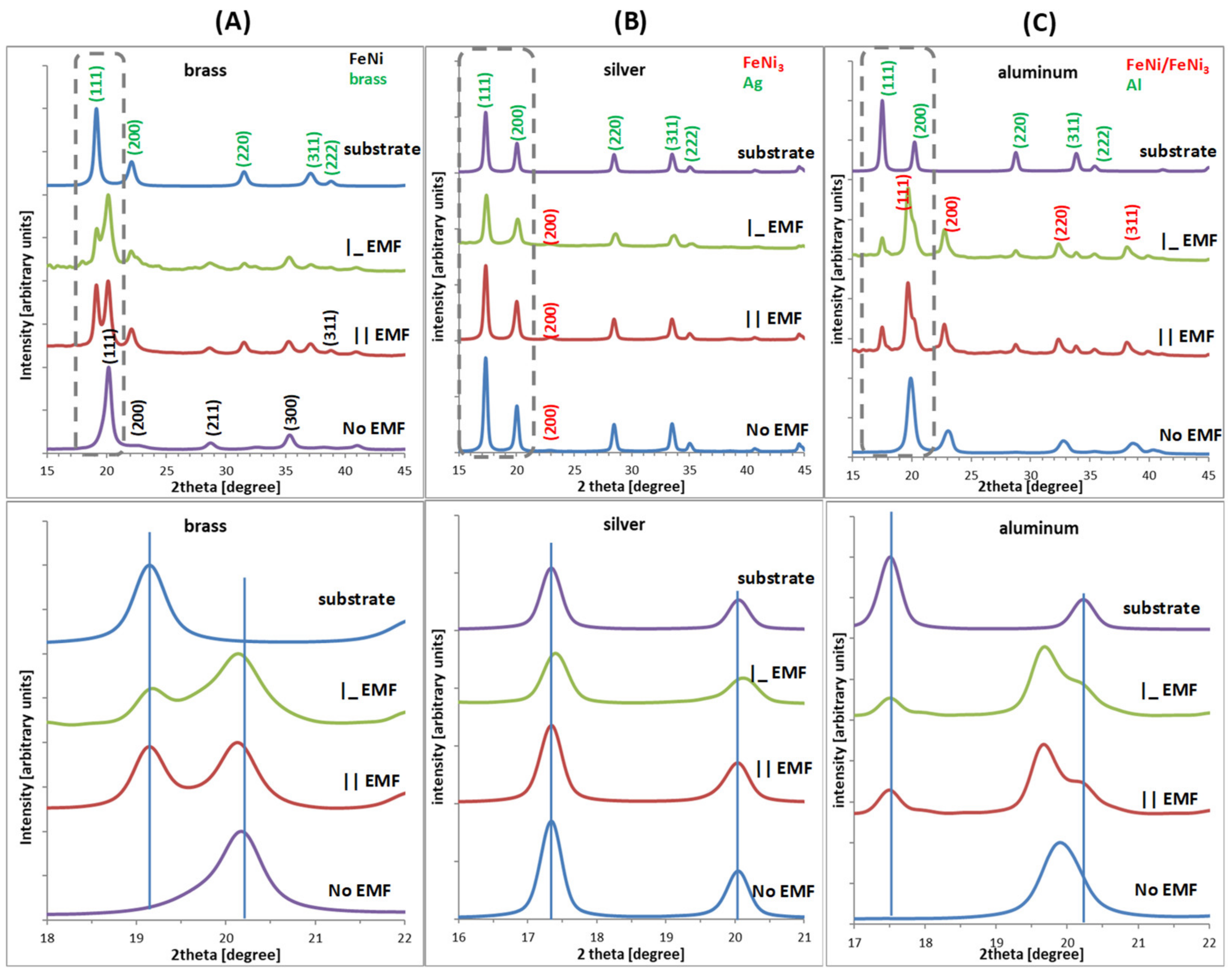
3.2. X-ray Diffraction

The crystalline structures of the FeNi alloys deposited on different substrates and in the external magnetic field (EMF) presence are shown in Figure 6. Here, the full range of measurements (upper row), as well as a focused view around the most intense peaks (lower row), are depicted. XRD patterns change as a result of applying three kinds of substrates of the same crystallographic structure. To the presented diffractograms, proper Miller indices (hkl) were assigned typical for substrates (metallic Ag, Al, and CuZn) and the crystal structures of the studied alloys (FeNi or FeNi3) [36,37]. Electrodeposition of FeNi films on brass without the EMF application results in growth that is typical for FeNi crystal structure. Both settings of the EMF result in the mixture of a pattern typical for the substrate and FeNi alloy that is correlated to the reduced film thickness (Figure 5) [35,36,37,38,39]. For the Ag substrate in all considered cases (with or without the EMF), the obtained layers were almost five times thinner than film obtained on the other substrates (brass, aluminum—Figure 5). The thickness remained in correlation with the analyzed diffractograms (Figure 6) and affected the electrodeposited film very strongly (its crystal structure). The absence of the FeNi or FeNi3 peaks is the result of the dominant occurrence of an amorphous structure [40,41,42,43,44]. Diffractograms registered for FeNi film deposited on the aluminum substrate support the following conclusions: (i) electrodeposition without EMF yields a crystal structure typical for FeNi or FeNi3 (however, due to elemental composition, FeNi3 is less favorable but due to line width mixture cannot be neglected); (ii) the application of an external magnetic field caused the thinner FeNi film growth. It also had a visible effect on increasing the nickel content in the percentage composition of the formed FeNi layer (toward FeNi3) and caused a drastic decrease in its thickness (similar to the case of the silver substrate)—Figure 4. The film composition and its crystal structure are very similar regardless of EMF orientation. For the diffractograms collected in Figure 5, the basic parameters of the films crystal structures were estimated. The average diffracting zone and thereby the crystallites’ size, Dhkl, was calculated according to Scherrer’s formula [45,46,47,48,49].
Based on FeNi and FeNi3 film patterns, the estimation of crystal cell parameters, respectively, for brass and Al allows to summarize that the average values of a range from 3.56 to 3.60 and 3.59 to 4.04. These are close to the theoretical values of a = 3.537 Å in FeNi3 (JCPDS Card No. 65-3244, mp-1418) and c = 3.581 Å in FeNi (JCPDS Card No. 47-1405, mp-2213) [36,37,43,50]. Calculations of the crystals’ average size provide us with a rough estimation about the layers’ growth. In both cases (brass and Al), the crystallites are larger when grown without the external magnetic field, respectively, d = 12.0 ± 0.5 and 6.5 ± 0.5 nm. When the external magnetic field is present, the average size of the crystallites reduces to 8.0–9.0 and 3.9–3.5 nm. In the case of Ag, these values cannot be estimated since the FeNi film grows mostly as an amorphous layer. Therefore, no diffraction peaks typical for these structures were identified. The above values were calculated using Scherrer’s formula from XRD peak broadening [47,50,51,52,53].

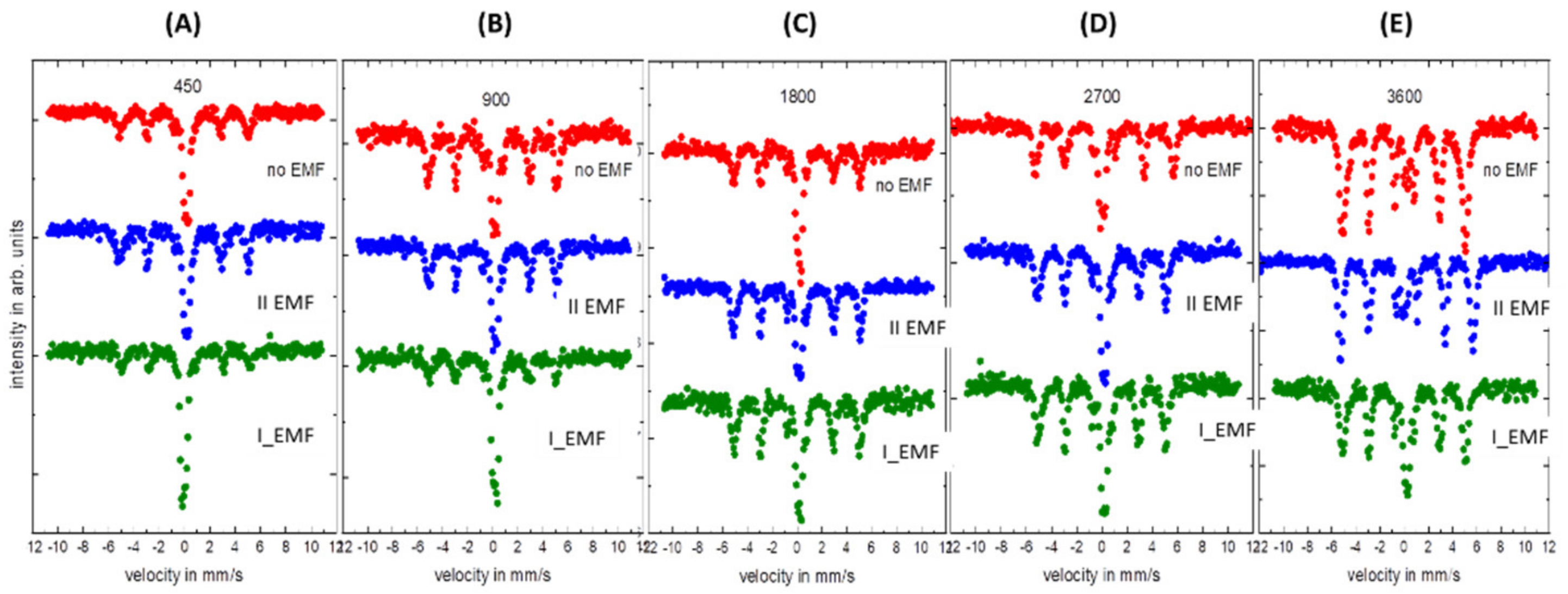
3.3. Mössbauer Spectroscopy

The Mössbauer spectra depicted in Figure 7 were collected for FeNi film deposited on Al with respect to the deposition time (A–E) and the presence or absence of the external magnetic field. It is clear that for a short deposition time (450 s—A), the obtained layer is the thinnest, and therefore registered spectra consist of mainly two subspectra: narrow doublet and sextet. The relative ratio between these two subspectra varies with the presence or absence of the external magnetic field. Clearly, regardless of the deposition time, the sextet is more intensive in respect to the doublet for the presence of perpendicular orientation of the external magnetic field during the deposition process. The least intensive sextet is obtained for parallel orientation of the magnetic field in respect to the sample plane. Deposition without the external magnetic field results in a middle case. With an increasing deposition time, the relative ratio between sextet and doublet changes, so that the sextet dominates more and more over the doublet. For 3600 s, almost the whole spectrum is dominated by the sextet. In two extreme cases (450 s and 3600 s), the doublet or sextet dominates, respectively. The hyperfine parameters of the doublet are typical for the Fe3+ and sextet for the FeNi alloys [50,54,55,56]. Fitted average hyperfine magnetic field (Bhf) values are around 31.5±0.5 T, and the isomer shift (IS) is 0.03±0.01 mm/s (sextet). The registered doublet is most probably caused by now well-magnetically developed part of the film. It is on average equal 0.15±0.05 mm/s. The intensity ratio of the subspectra changes as it is presented in Table 1.

4. Conclusions

A series of FeNi alloys were grown from the electrolyte containing Fe and Ni ions in DC mode, on the selected substrates (brass, Ag, Al) oriented parallel or perpendicular to the external magnetic field. The properties of the deposits were investigated as a function of the iron–nickel layer thickness, the percentage content of elements in the alloys, and the crystal lattice parameters. The substrates influenced the elemental composition of iron and nickel in the FeNi films and, consequently, their crystal structure. The aluminum substrate increases the magnetizing field effect, and the brass and silver substrates decrease it. Applied substrates varied in the terms of their cell parameters(CuZn—3.62–3.69 Å, Ag—4.08 Å, Al—2.86 Å) and thus affect the early stages of the deposited alloy layer and its subsequent growth. The results allowed us to clarify the crystal composition, which has an impact on the physical and chemical properties of the alloy layers. As well as the chemical composition of the substrate, and its crystal structure, another very important aspect is the affinity to oxygen which influences the growth process. That results in a decrease of adhesion of the deposit in the case of the Al substrate. The applied external magnetic field significantly reduces film thickness regardless of the selected substrate. Additionally, EMF influences the morphology of the obtained layers (large number of nucleation centers, nucleation fluctuation). Usage of various methods to analyze the obtained results allowed for the above conclusions to be drawn. Supplemented knowledge about the above presented aspects allows a more precise tailoring of the material to the needs of a wide range of industries and end-users.

Author Contributions

Conceptualization, B.K.-S., A.M.B., and U.K.; methodology, U.K.; software, B.K.-S.; validation, B.K.-S., A.M.B., and U.K.; formal analysis, U.K.; investigation, A.M.B. and U.K.; resources, U.K.; data curation, B.K.-S., A.M.B., and U.K.; writing—original draft preparation, A.M.B.; writing—review and editing, B.K.-S., A.M.B., and U.K.; visualization, A.B and U.K.; supervision, B.K.-S.; project administration, A.M.B.; funding acquisition, A.M.B. All authors have read and agreed to the published version of the manuscript.

Funding

This work was partially financed by the EU fund as part of the projects: POPW.01.03.00-20.034/09 and POPW.01.03.00-20-004/11, and WZ/WE-IA/2/2020 supported by a research subsidy of the Institute of Automation, Electronics and Electrotechnology Bialystok University of Technology for 2021, assigned as teamwork. Mössbauer measurements were completed thanks to close collaboration with the Faculty of Physics, University of Bialystok.

Data Availability Statement

Not applicable.

Conflicts of Interest

The authors declare no conflict of interest.

References

  1. Tateno, S.; Hirose, K.; Komabayashi, T.; Tateno, H.; Ohishi, Y. The structure of Fe-Ni alloy in Earth’s inner core. Geophys. Res. Lett. 2012, 39, L12305. [Google Scholar] [CrossRef] [Green Version]
  2. Martin, P.M. DepositionTechnologies for Films and Coatings. Science, Applications and Technology, 3rd ed.; Elsevier Inc.: Oxford, UK, 2010. [Google Scholar]
  3. Milchev, A.; Heerman, L. Electrochemical nucleation and growth of nano- and microparticles: Some theoretical and experimental aspects. Electrochim. Acta 2003, 48, 2903–2913. [Google Scholar] [CrossRef]
  4. Brenner, A. Electrodeposition of Alloys; Academic Press: New York, NY, USA, 1963. [Google Scholar]
  5. Dimitrievich, T.R. Normal electrochemical deposition of FeNi films. Adv. Res. 2017, 11, 1–10. [Google Scholar] [CrossRef]
  6. Popov, K.I.; Djokić, S.S.; Nikolić, N.D.; Jović, V.D. Morphology of Electrochemically and Chemically Deposited Metals; Springer International Publishing: Cham, Switzerland, 2016. [Google Scholar]
  7. Gurrappa, I.; Binder, L. Electrodeposition o nanostructured coatings and their characterization—A review. Sci. Technol. Adv. Mater. 2008, 9, 043001. [Google Scholar] [CrossRef]
  8. Rezende, T.G.L.; Cezar, D.V.; do Lago, D.C.B.; Senna, L.F. A review of Corrosion Resistance Nanocomposite Coatings. In Electrodeposition of Composite Materials; Mohamed, A.M.A., Golden, T.G., Eds.; IntechOpen: London, UK, 2016; pp. 147–185. [Google Scholar] [CrossRef] [Green Version]
  9. Sitek, J.; Degmová, J.; Sedlačková, K.; Dekan, J. Mössbauer Spectroscopy of Fe-Ni-Nb-B Alloy in Weak Magnetic Field. J. Mod. Phys. 2012, 3, 274–277. [Google Scholar] [CrossRef] [Green Version]
  10. Kalska-Szostko, B.; Wykowska, U.; Satuła, D. Magnetic nanowires (Fe, Fe-Co, Fe-Ni)—Magnetic moment reorientation in respect of wires composition. Nukleonika 2015, 60, 63–67. [Google Scholar] [CrossRef] [Green Version]
  11. Kuru, H.; Kockar, H.; Alper, M. Giant magnetoresistance (GMR) behavior of electrodeposited NiFe/Cu multilayers: Dependence of non-magnetic and magnetic layer thickness. J. Magn. Magn. Mater. 2017, 444, 132–139. [Google Scholar] [CrossRef]
  12. Okamoto, N.; Wang, F.; Watanabe, T. Adhesion of Electrodeposited Copper, Nickel and Silver films on Copper, Nickel and Silver Substrates. Mater. Trans. 2004, 45, 3330–3333. [Google Scholar] [CrossRef] [Green Version]
  13. Nweze, C.I.; Ekpunobi, A.J. Electrodeposition of Zinc Selenide Films on Different Substrates and its Characterization. Int. J. Sci. Technol. 2014, 3, 201–203. [Google Scholar]
  14. Koschichow, D.; Mutschke, G.; Yang, X.; Bund, A.; Fröhlich, J. Numerical Simulation of the Onset of Mass Transfer and Convection in Copper Electrolysis Subjected to a Magnetic Field. Russ. J. Electrochem. 2012, 48, 682–691. [Google Scholar] [CrossRef]
  15. Białostocka, A.; Idzkowski, A. The Effect of Ground Changes and the Setting of External Magnetic Field on Electroplating FeNi Layers: Progress in Automation, Robotics and Measurement Techniques. In Automation 2019; Szewczyk, R., Zieliński, C., Kaliczyńska, M., Eds.; Springer: Cham, Switzerland, 2019; pp. 684–696. [Google Scholar]
  16. Thanh, N.T.K.; Maclean, N.; Mahiddine, S. Mechanisms of Nucleation and Growth of Nanoparticles in Solution. Chem. Rev. 2014, 114, 7610–7630. [Google Scholar] [CrossRef] [PubMed]
  17. Meena, S.P.; Ashokkumar, R.; Ranjith Kumar, E. Effects o Cr Doping Concentration on Structural, Morphology, Mechanical and Magnetic Properties of Electrodeposited NiCoCr Thin Films. J. Inorg. Organomet. Polym. 2019, 29, 1094–1099. [Google Scholar] [CrossRef]
  18. Kim, J.; Kim, M.; Herrault, F.; Park, J.; Allen, M.G. Highly laminated soft magnetic electroplated CoNiFe thick films. IEEE Magn. Lett. 2013, 4, 5000204. [Google Scholar] [CrossRef]
  19. Kalska-Szostko, B.; Giersig, M.; Fumagalli, P. Influence of the shape on the magneto-optic properties of nanosized islands. Mater. Chem. Phys. 2019, 228, 27–31. [Google Scholar] [CrossRef]
  20. Kalska-Szostko, B.; Nordström, E.; Häggström, L.; Blomvist, P.; Wäppling, R. Fe/V multilayers studied by CEMS. J. Alloy Compd. 2003, 348, 208–213. [Google Scholar] [CrossRef]
  21. Fernández, E.; Svalov, A.V.; García-Arribas, A.; Feuchtwanger, J.; Barandiaran, J.M.; Kurlyandskaya, G.V. High Performance Magnetoimpedance in FeNi/Ti Nanostructured Multilayers with Opened Magnetic Flux. J. Nanosci. Nanotechnol. 2012, 12, 7496–7500. [Google Scholar] [CrossRef]
  22. Li, B.; Kavaldzhiev, M.N.; Kosel, J. Flexible magnetoimpedance sensor. J. Magn. Magn. Mater. 2015, 378, 499–505. [Google Scholar] [CrossRef]
  23. Beach, R.S.; Smith, N.; Platt, C.L.; Jeffers, F.; Berkowitz, A.E. Magneto-impedance effect in NiFe plated wire. Appl. Phys. Lett. 1996, 68, 2753–2755. [Google Scholar] [CrossRef]
  24. Melzer, M.; Makarov, D.; Calvimontes, A.; Karnaushenko, D.; Baunack, S.; Kaltofen, R.; Mei, Y.; Schmidt, O.G. Stretchable Magnetoelectronics. Nano. Lett. 2011, 11, 2522–2526. [Google Scholar] [CrossRef] [Green Version]
  25. Grimes, C.A. Sputter Deposition of Magnetic Thin Films Onto Plastic: The Effect of Undercoat And Spacerlayer Composition On The Magnetic Properties Of Multilayer Permalloy Thin Films. IEEE T. Magn. 1995, 31, 4109–4111. [Google Scholar] [CrossRef]
  26. Białostocka, A.M.; Klekotka, U.; Kalska-Szostko, B. The Effect of a Substrate Material on Composition Gradients of Fe-Ni Films obtained by Electrodeposition. Sci. Rep. 2020, 10, 1029–1037. [Google Scholar] [CrossRef] [PubMed]
  27. Kądziołka-Gaweł, M.; Babilas, R.; Granek, K. Mössbauer Study of Some Intermetallic Compounds Fe80-xNixB20 (x = 8, 16, 24, 28). Acta Phys. Pol. A 2018, 133, 651–653. [Google Scholar] [CrossRef]
  28. Białostocka, A.M.; Klekotka, U.; Kalska-Szostko, B. Modulation of Iron-Nickel Layers Composition by an External Magnetic Field. Chem. Eng. Commun. 2018, 206, 804–814. [Google Scholar] [CrossRef]
  29. Białostocka, A.M.; Klekotka, U.; Żabiński, P.; Kalska-Szostko, B. Microstructure evolution of Fe/Ni layers deposited by electroplating under an applied magnetic field. Magnetohydrodynamics 2017, 53, 309–319. [Google Scholar] [CrossRef]
  30. Ispas, A.; Matsushima, H.; Plieth, W.; Bund, A. Influence of a magnetic field on the electrodeposition of nickel-iron alloys. Electrochim. Acta 2007, 52, 2785–2795. [Google Scholar] [CrossRef]
  31. Yin, K.-M.; Wei, J.-H.; Fu, J.-R.; Popov, B.N.; Popova, S.N.; White, R.E. Mass Transport Effects on the Electrodeposition of Iron-Nickel Alloys at the Presence of Additives. J. Appl. Electrochem. 1995, 25, 543–555. [Google Scholar] [CrossRef]
  32. Rabia, J.; Tajamal, H.; Saliha, S.; Shahid, A.M. Magnetic Field Effects on the Microstructural Variation of Electrodeposited Nickel Film. J. Mater. Sci. Technol. 2011, 1, 481–487. [Google Scholar]
  33. Koza, J.A.; Mogi, I.; Tschulik, K.; Uhlemann, M.; Mickel, C.; Gebert, A.; Schultz, L. Electrocrystallisation of metallic films under the influence of an external homogeneous magnetic field—Early stages of the layer growth. Electrochim. Acta 2010, 55, 6533–6541. [Google Scholar] [CrossRef]
  34. Guittoum, A.; Layadi, A.; Tafat, H.; Bourzami, A.; Souami, N.; Lenoble, O. Structure, Mössbauer and magnetic studies of nanostructured Fe80Ni20 alloy elaborated by mechanical milling. Philos. Mag. 2008, 88, 1085–1098. [Google Scholar] [CrossRef]
  35. Bokuniaeva, A.O.; Vorokh, A.S. Estimation of particle size using the Debye equation and the Scherrer formula for polyphasic TiO2 powder. J. Phys. Conf. Ser. 2019, 1410, 012057. [Google Scholar] [CrossRef]
  36. Persson, K. Materials Data on FeNi (SG:123) by Materials Project. 2016. Available online: https://www.osti.gov/dataexplorer/biblio/dataset/1197364 (accessed on 1 December 2021).
  37. Persson, K. Materials Data on FeNi3 (SG:221) by Materials Project. 2015. Available online: https://www.osti.gov/dataexplorer/biblio/dataset/1190197 (accessed on 1 December 2021).
  38. Rabiei, M.; Palevicius, A.; Monshi, A.; Nasiri, S.; Vilkauskas, A.; Janusas, G. Comparing Methods for Calculating Nano Crystal Size of Natural Hydroxyapatite Using X-ray Diffraction. Nanomaterials 2020, 10, 1627. [Google Scholar] [CrossRef] [PubMed]
  39. Holzwarth, U.; Gibson, N. The Scherrer equation versus the ‘Debye-Scherrer equation’. Nat. Nanotech. 2011, 6, 534. [Google Scholar] [CrossRef] [PubMed]
  40. Ispas, A.; Matsushima, H.; Bund, A.; Bozzini, B. Nucleation and growth of thin nickel layers under the influence of a magnetic field. J. Electroanal. Chem. 2009, 626, 174–182. [Google Scholar] [CrossRef]
  41. Wiecinski, P.; Garbacz, H.; Murakami, H.; Kurzydłowski, K. Effect of grain size on reactive diffusion between titanium and aluminium. Phys. Status Solidi 2010, 7, 1395–1398. [Google Scholar] [CrossRef]
  42. Wu, C.; Wang, X.; Pei, W.; Zhao, D.; Wang, K.; Lia, G.; Wang, Q. Tailoring the shape and size of wet-chemical synthesized FePt nanoparticles by controlling nucleation and growth with high magnetic field. Nanoscale 2019, 11, 15023–15028. [Google Scholar] [CrossRef]
  43. Trong, D.N.; Long, V.C. Effects of number of atoms, shell thickness, and temperature on the structure of Fe nanoparticles amorphous by molecular dynamics method. Appl. Mech. Mater. 2021, 9976633. [Google Scholar] [CrossRef]
  44. Minh, H.D.T.; Coman, G.; Quang, H.N.; Trong, D.N. Influence of heating rate, temperature, pressure on the structure, and phase transition of amorphous Ni material: A molecular dynamics study. Heliyon 2020, 6, e05548. [Google Scholar] [CrossRef]
  45. Link, S.; Ivanov, S.; Dimitrova, A.; Krischok, S.; Bund, A. Understanding the initial stages of Si electrodeposition under diffusion kinetic limitation in ionic liuid-based electrolytes. J. Cryst. Growth 2020, 531, 125346. [Google Scholar] [CrossRef]
  46. Kalsen, S.; Alper, M.; Kockar, H.; Haciismailoglu, M.; Karaagac, O.; Kuru, H. Properites of Electrodeposited CoFeNi/Cu Superlattices: The Effect of CoFeNi and Cu Layers Thicknesses. J. Supercond. Nov. Magn. 2013, 26, 813–817. [Google Scholar] [CrossRef]
  47. Kuru, H.; Aytekin, N.Ç.; Köçkar, H.; Haciismailoğlu, M.; Alper, M. Effect of NiFe layer thickness on properties of NiFe/Cu superlattices electrodeposited on titanium substrate. J. Mater. Sci.-Mater. Electron. 2019, 30, 17879–17889. [Google Scholar] [CrossRef]
  48. Szczurek, T.; Rausch, T.; Schlesinger, M.; Snyder, D.D.; Olk, C.H. Induced Crystallographic Orientations in Electrodeposited Ni-Cu Multilayers. J. Electrochem. Soc. 1999, 146, 1777–1779. [Google Scholar] [CrossRef]
  49. Tokarz, A.; Nitkiewicz, Z.; Wolkenberg, A. The dependence of magnetic properties on crystallographic structure of electrochemically deposited Ni/Cu superlattices. Electron. Technol.-Internet J. 2003, 35, 1–4. [Google Scholar]
  50. Kądziołka-Gaweł, M.; Zarek, M.; Popiel, E.; Chrobak, A. The Crystal Structure and Magnetic Properties of Selected fccFeNi and Fe40Ni40B20 Alloys. Acta Phys. Pol. A 2010, 117, 412–414. [Google Scholar] [CrossRef]
  51. Seo, J.H.; Kim, J.K.; Yim, T.H.; Park, Y.B. Textures and Grain Growth in Nanocrystalline Fe-Ni Alloys. Mater. Sci. 2005, 475–479, 3483–3488. [Google Scholar] [CrossRef]
  52. Rezaei, M.; Haghshenas, D.F.; Ghorbani, M.; Dolati, A. Electrochemical Behavior of Nanostructured Fe-Pd Alloy During Electrodeposition on Different Substrates. J. Electrochem. Sci. Technol. 2018, 9, 202–211. [Google Scholar] [CrossRef] [Green Version]
  53. Matsui, I.; Mori, H.; Kawakatsu, T.; Takigawa, Y.; Uesugi, T.; Higashi, K. Mechanical Behavior of Electrodeposited Bulk Nanocrystalline Fe-Ni Alloys. Mater. Res. 2015, 18, 95–100. [Google Scholar] [CrossRef] [Green Version]
  54. Kalska-Szostko, B.; Klekotka, U.; Satuła, D. Core-shell magnetic nanowires fabrication and characterization. Appl. Surf. Sci. 2017, 396, 1855–1859. [Google Scholar] [CrossRef]
  55. Kalska-Szostko, B.; Klekotka, U.; Olszewski, W.; Satuła, D. Multilayered and alloyed Fe-Co and Fe-Ninanowires physicochemical studies. J. Magn. Magn. Mater. 2019, 484, 67–73. [Google Scholar] [CrossRef]
  56. Lehlooh, A.F.D.; Mahmood, S.H. Mössbauer Spectroscopy Study of Iron Nickel Alloys. Hyperfine Interact. 2002, 139, 387–392. [Google Scholar] [CrossRef]
Figure 1. Schematic presentation of the deposition set-up: (A) without the EMF (side view); (B) perpendicular orientation of the EMF (top view); (C) parallel orientation of the EMF (top view), in respect to the surface plane, and photo of deposition set-up (D).
Energies 15 03520 g001
Figure 2. SEM images of the FeNi film on different substrates (magnification—×5000): (A) without external magnetic field; both in presence of external magnetic field (B) II, (C) I_ orientation in respect to surface plane.
Energies 15 03520 g002
Figure 3. An example EDX spectra of the deposited FeNi films on different substrates (A) brass, (B) silver, and (C) aluminum, in the presence of II external magnetic field orientation in respect to surface plane.
Energies 15 03520 g003
Figure 4. Time influence on the Fe content in the FeNi alloy deposited on different substrates, current density—50.0 mA/cm2: (A) without EMF, (B) parallel EMF, (C) perpendicular EMF.
Energies 15 03520 g004
Figure 5. EMF influence on the Fe and Ni content in the FeNi alloy (blocks, right side) and on its thickness (line, left side); substrates: (A) brass, (B) silver, (C) aluminum, current density 50.0 mA/cm2, time of deposition—3600 s.
Energies 15 03520 g005
Figure 6. Diffraction XRD patterns of FeNi electrodeposited films divided for different substrates: (A) brass, (B) silver, and (C) aluminium, time of deposition—3600 s.
Energies 15 03520 g006
Figure 7. Mössbauer spectra of the FeNi alloys on aluminium substrate: (A) 450 s, (B) 900 s, (C) 1800 s, (D) 2700 s, (E) 3600 s.
Energies 15 03520 g007
Table 1. Intensity ratio of sextet to doublet (s/d ± 0.5%).
450 s900 s1800 s2700 s3600 s
Without EMF43.3/56.766.8/33.248.3/51.766.0/34.088.9/11.1
I_ EMF53.7/46.359.2/40.859.5/40.560.7/39.385.8/14.2
II27.6/72.433.3/66.763.8/36.263.5/36.569.0/31.0
Publisher’s Note: MDPI stays neutral with regard to jurisdictional claims in published maps and institutional affiliations.

