Article

Analysis and Calculation of Crosstalk for Twisted Communication Cables in Umbilical Cable

College of Electrical Engineering, Zhejiang University, Hangzhou 310027, China
*
Author to whom correspondence should be addressed.
Energies 2022, 15(10), 3501; https://doi.org/10.3390/en15103501
Submission received: 19 April 2022 / Revised: 8 May 2022 / Accepted: 9 May 2022 / Published: 10 May 2022

Abstract

:
An umbilical cable is a compactly integrated cable consisting of electrical power cables, communication (electric signal) cables, and chemical transposition tubes. An umbilical cable is widely used in developing oil and gas resources of deep and ultra-deep water. With the increment of the length and the functional integration of umbilical cables, the crosstalk becomes a crucial issue in the cable design, and needs to be evaluated carefully before the fabrication and installation. Moreover, the twisted structure of communication cable cores has incurred extra difficulties to the crosstalk calculation. Nevertheless, it is not an easy task to model the complex twisted structure in existing models and methods of the crosstalk computation. In this regard, this paper proposes a numerical methodology for the crosstalk calculation considering the multi-conductor twisted structure of the cable cores. In the methodology, the four-wire twisted structure is modelled as a cascade of uniform multiconductor transmission line (MTL) sections, each wire section covering a length of 1/4 pitch, with abrupt interchanges of wire positions at the ends. The chain-parameter equation is introduced to describe the voltage and current transfer relationship in each MTL section. To obtain the numerical solutions of the twisted cable system, the port constraint equations and the permutation matrices are also required and developed. The per-unit-length parameters of the umbilical cable system are computed by numerical methods. The feasibility to engineering applications and accuracy of the proposed methodology is validated by experimental results, and the crosstalk characteristics of communication cables in a typical umbilical cable under different operating conditions are investigated.

1. Introduction

An umbilical cable is a compactly aggregated cable consisting of electrical power cables, communication cables and chemical transposition tubes, and has been widely used in developing marine resources of deep and ultra-deep water. After more than 50 years of development, umbilical cables have progressed from the hydraulic type to the electro-hydraulic hybrid type, becoming more and more integrated and complex in both structures and functions. The umbilical cable today can simultaneously deliver electric power, transmit the controlling signals and the status signals of an equipment, and transport the hydraulic oil and chemicals for undersea facilities [1,2,3]. As a result, the crosstalk will take place between communication cables in an umbilical cable with the growing integration of cables and tubes in an umbilical cable. As is well known, crosstalk is an essential concern in EMC and EMI design of modern electronic and electrical systems and devices since, for example, it will inevitably degrade the reliability of communications between onshore and undersea equipment. Therefore, it is necessary to calculate and evaluate the crosstalk of communication cables in umbilical cable designs.
To investigate the crosstalk of an umbilical cable, a great deal of research has been reported. In References [4,5], the induced voltages of communication cables in an umbilical cable are calculated from the solution of the vector magnetic potential. However, only inductive coupling is considered, and the capacitive coupling is ignored, as is the effect of the twisted structure. In order to consider the influence of twisted structures on the crosstalk, References [6,7] propose a similar method by dividing the twisted cable bundle into a series of cross sections along the length. Specifically, in Reference [6], the umbilical cable is substituted with N number of cascaded cross sections within the least common multiple length. The 2-D finite element analysis is conducted to obtain the induced terminal voltage in each cross section. The induced terminal voltages of all cross sections are averaged as the terminal voltage of the whole line. In [7], the twisted cable bundle, which includes a pair of twisted cables as excitation wires and a single cable as victim wire, is divided into 128 sections per twist. Each section is analyzed numerically and the distribution of the crosstalk current in the victim wire is derived. References [6,7] perform numerical calculations of electromagnetic field for each section, which results in undesirable computing time and leads to a methodology impractical in engineering applications. Reference [8] applies the multiconductor transmission line (MTL) theory to solve the crosstalk issue, and proposes the well-known cascaded circuit model to deal with the twisted wire pairs. The model in [8] considers both the twisted structure and the computational time. However, this model is applicable only to the twisted wire pairs, and cannot be used to study complex stranded wires composed of multi conductors.
From the previous literature review, one can observe that so far there is still no any general methodology to calculate the crosstalk of a multi-conductor twisted structure in existing literatures. In this respect, this paper contributes a new discretization method for four-core twisted cables to better characterize the multi-conductor twisted structure, and develops a crosstalk model by combining MTL theory with the transposition technique. Moreover, the proposed crosstalk model is a circuit model in nature, and the model parameters are derived by numerical solutions of one umbilical cross section. Consequently, the computational cost of the proposed methodology is relatively small. Experimental studies validate that the proposed crosstalk model can give relatively precise crosstalk values. Finally, the crosstalk characteristics between communication cables in a prototype umbilical cable are explored.

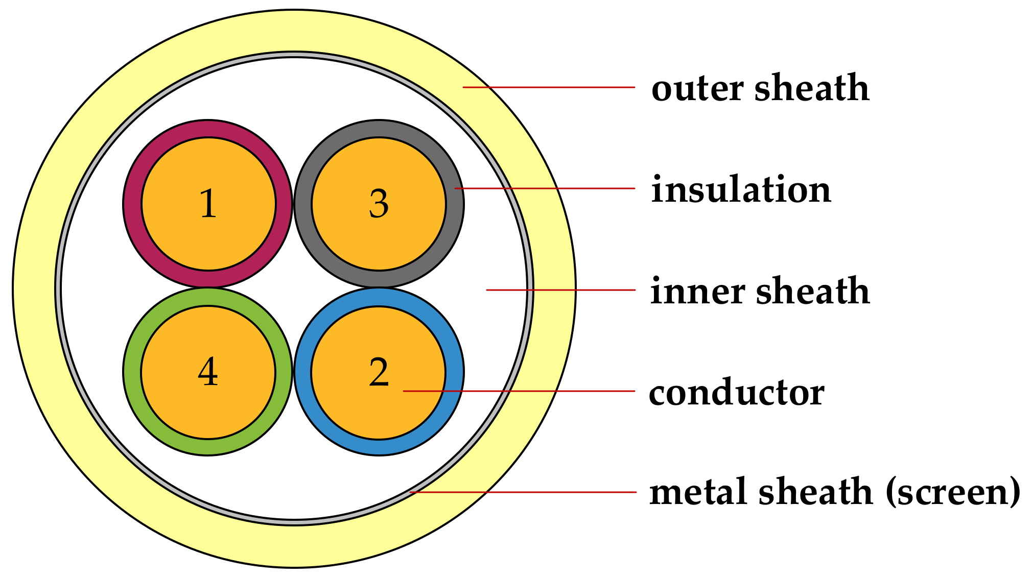
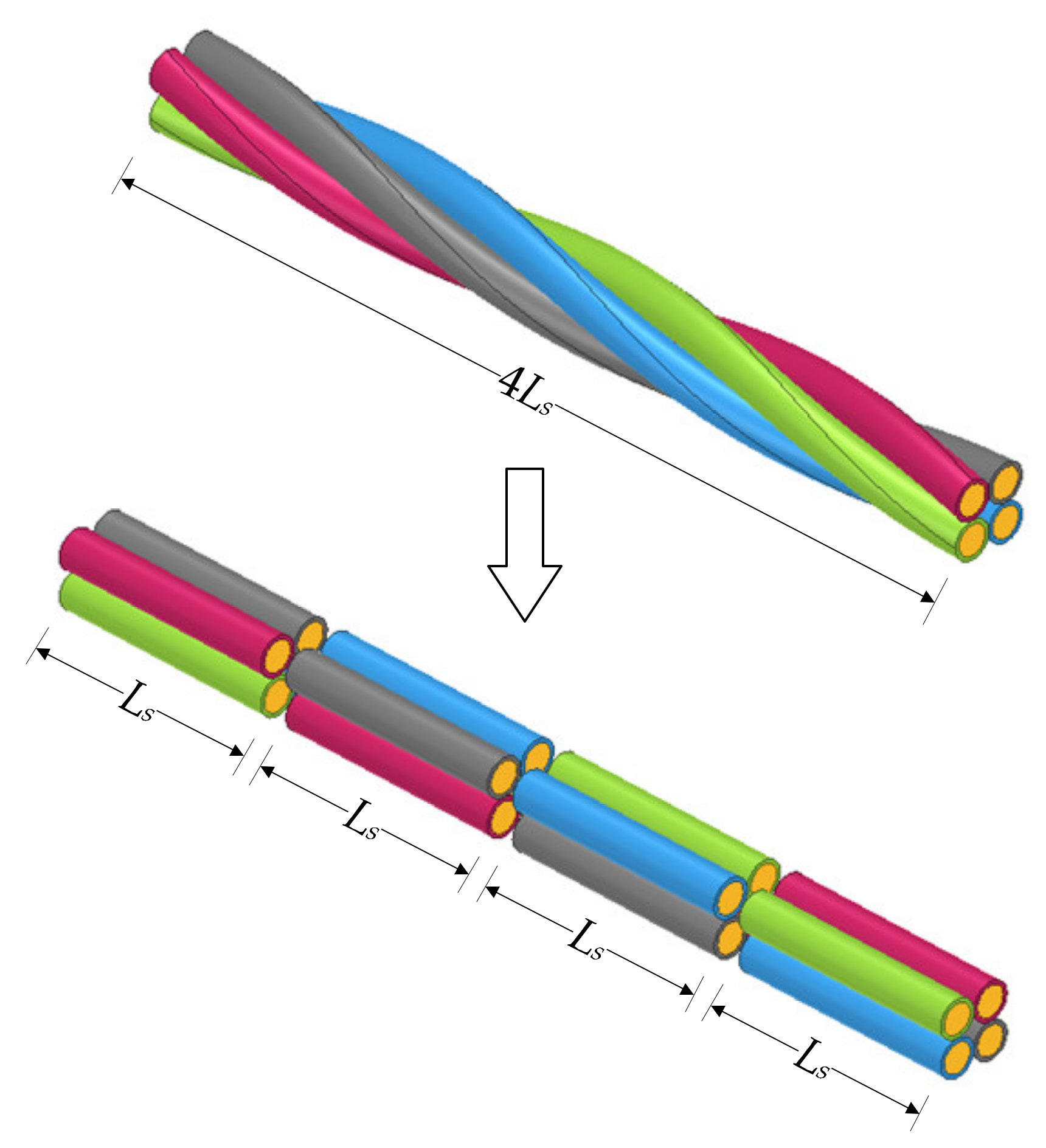
2. Crosstalk Model Considering Twisted Structure

One takes a communication cable of four conductors twisted with each other along the length as a case study. The cross section of the communication cable is shown in Figure 1, with four conductors numbered 1, 2, 3 and 4, respectively. In order to simplify the structure characteristics and retain the basic helical topology, the cable cores are regarded as a cascade of uniform MTL sections with abrupt interchanges of conductor positions at the end of each section, as shown in Figure 2. Specifically, the distributed circuit parameters are uniform in one section; the four conductors rotate 90 degrees along the helical direction at the end of each section without any increment in cable length, which is an abrupt transposition. The length of each MTL section is represented by Ls, which equals to 1/4 pitch. The abrupt transposition model of the communication cable consisting of four twisted conductors is shown in Figure 3.
The abrupt transposition model approximates the nonuniform transmission lines as a piecewise uniform MTL. Each uniform MTL section can be characterized by a chain-parameter matrix. For a MTL section starting at axial position z1 and ending at axial position z2, the phasor voltages and currents at the two ends of the lines are related by the following chain-parameter equation as:
V ^ z 2 I ^ z 2 = Φ ^ z 2 z 1 V ^ z 1 I ^ z 1 = Φ ^ 11 z 2 z 1 Φ ^ 12 z 2 z 1 Φ ^ 21 z 2 z 1 Φ ^ 22 z 2 z 1 V ^ z 1 I ^ z 1
where Φ ^ denotes the chain-parameter matrix, Φ ^ i j i , j = 1 , 2 denote the submatrices of Φ ^ . One now sets that z2 minus z1 equals to Ls. If Ls is much smaller than the wavelength of the electromagnetic wave, the MTL section with length Ls can be modeled by a lumped-Pi structure [9], and the corresponding chain-parameter matrix is:
Φ ^ Π L s = E n + 1 2 Z ^ Y ^ L s 2 Z ^ L s Y ^ L s 1 4 Y ^ Z ^ Y ^ L s 3 E n + 1 2 Y ^ Z ^ L s 2
where the subscript n represents the number of signal conductors in MTL (n is an integral multiple of 4 in this paper). The per-unit-length impedance matrix, Z ^ , and admittance matrix, Y ^ , are calculated from the per-unit-length resistance R, conductance G, inductance L, and capacitance C matrices as:
Z ^ = R + j ω L Y ^ = G + j ω C
The whole chain-parameter matrix of the nonuniform transmission lines by a series of piecewise uniform MTL sections can be obtained as the product of the chain-parameter matrices of the sections and the permutation matrices of the terminals. For a communication cable with an axial length of NLs, the terminal relations constructed by the whole chain-parameter matrix is:
V ^ z 2 N 1 I ^ z 2 N 1 = Φ ^ L s P Φ ^ L s N 1 V ^ 0 I ^ 0
where P is the permutation matrix to transpose the conductor positions. The P matrix is a quasi-diagonal matrix and is given by:
P = d i a g o n a l 0 0 0 1 0 0 1 0 1 0 0 0 0 1 0 0 0 0 0 1 0 0 1 0 1 0 0 0 0 1 0 0 2 n × 2 n
where the operator diagonal represents constructing a quasi-diagonal matrix using the matrices in “{ }”.
The general relations of the phasor voltages and phasor currents at z = 0 and z = NLs in (4) involve 2n unknowns as V ^ i ( 0 ) and I ^ i ( 0 ) ( i = 1 : n ) . Therefore, one needs 2n constraint equations at the terminations to evaluate these degrees of freedom. Generally, the 2n constraint equations are the Thevenin equivalent characterizations or the Norton equivalent characterizations of the 2n terminal ports. If the signal conductor is shorted to the reference conductor, one must use the Thevenin equivalent characterization for this port, since the Norton equivalent characterization does not exist (the terminal admittance is infinite). Conversely, if the signal conductor is not connected to the reference conductor, which means there is an open circuit in this port, one must use the Norton equivalent characterization since the Thevenin equivalent characterization does not exist (the port has infinite impedance).
One takes the transmission line system consisting of two four-core communication cables with the specific terminal networks of Figure 4 as an example. The corresponding constraint equations can be given by the Norton equivalent characterization as:
I ^ 0 = I ^ S Y ^ S V ^ 0 I ^ N L s = I ^ L + Y ^ L V ^ N L s
where,
I ^ S = I ^ S 14 0 0 I ^ S 14 0 0 0 0 T I ^ L = 0 0 0 0 0 0 0 0 T
Y ^ S = 0 0 0 0 0 Y ^ c t Y ^ c t 0 0 Y ^ c t Y ^ c t 0 0 0 0 0 0 4 × 4
Y ^ L = Y ^ L u p Y ^ c t Y ^ c t 0 0 Y ^ c t Y ^ c t 0 0 0 0 Y ^ c t Y ^ c t 0 0 Y ^ c t Y ^ c t
Y ^ Lup = { Y ^ m e a s 0 Y ^ m e a s 0 0 Y ^ c t 0 Y ^ c t Y ^ m e a s 0 Y ^ m e a s 0 0 Y ^ c t 0 Y ^ c t ,   N = 4 k Y ^ c t 0 0 Y ^ c t 0 Y ^ m e a s Y ^ m e a s 0 0 Y ^ m e a s Y ^ m e a s 0 Y ^ c t 0 0 Y ^ c t ,   N = 4 k + 1 Y ^ c t 0 Y ^ c t 0 0 Y ^ m e a s 0 Y ^ m e a s Y ^ c t 0 Y ^ c t 0 0 Y ^ m e a s 0 Y ^ m e a s ,   N = 4 k + 2 Y ^ m e a s 0 0 Y ^ m e a s 0 Y ^ c t Y ^ c t 0 0 Y ^ c t Y ^ c t 0 Y ^ m e a s 0 0 Y ^ m e a s ,   N = 4 k + 3 k   is an integer
In Equations (7)–(10), I ^ S 14 denotes the equivalent current source of the signal source of Figure 4; Y ^ c t denotes the admittance of every shorted connection in terminal constraint networks of Figure 4; Y ^ m e a s denotes the admittance of the resistor for measuring the crosstalk voltage. One substitutes the general forms of the solutions in (4) into the terminal constraint equations given in (6) to yield the matrix equations for determining V ^ i ( 0 ) and I ^ i ( 0 ) ( i = 1 : n ) as:
Y ^ S E n Y ^ L Φ ^ 11 N L s Φ ^ 21 N L s Y ^ L Φ ^ 12 N L s Φ ^ 22 N L s V ^ 0 I ^ 0 = I ^ S I ^ L
Once these 2n unknowns are solved, the n terminal voltages and n terminal currents at z = NLs can be obtained from the terminal relations of (4). The crosstalk can then be calculated by:
X T = 20 lg V d V s
where XT denotes the crosstalk value, Vs denotes the voltage magnitude of the exciting port, Vd denotes the voltage magnitude of the receiving port.
Figure 4. The schematic diagram of the specific terminal networks in a transmission line system.
Energies 15 03501 g004

3. Per-Unit-Length Parameters of the Cable

The per-unit-length parameter matrices of R, L, G, and C for the umbilical cable are the essential ingredients of the proposed crosstalk model, and have the specific form as follows:
R = r 1 + r 0 r 0 r 0 r 0 r 2 + r 0 r 0 r 0 r 0 r n + r 0
L = l 11 l 12 l 1 n l 12 l 22 l 2 n l 1 n l 2 n l n n
G = k = 1 n g 1 k g 12 g 1 n g 12 k = 1 n g 2 k g 2 n g 1 n g 2 n k = 1 n g n k
C = k = 1 n c 1 k c 12 c 1 n c 12 k = 1 n c 2 k c 2 n c 1 n c 2 n k = 1 n c n k
where ri is the per-unit-length resistance of the ith conductor, r0 is the per-unit-length resistance of the reference conductor, lii is the per-unit-length self-inductance of the ith loop, lij is the per-unit-length mutual inductance between the ith loop and the jth loop, gii is the per-unit-length conductance between the ith conductor and the reference conductor, gij is the per-unit-length conductance between the ith conductor and the jth conductor, cii is the per-unit-length self-capacitance between the ith conductor and the reference conductor, cij is the per-unit-length mutual capacitance between the ith conductor and the jth conductor (i, j = 1, 2, …, n; ij). However, it is difficult to give analytical solutions for the entries in the per-unit-length parameter matrices of the umbilical cable due to the inhomogeneous dielectric medium surrounding the conductors and the complex configuration of the umbilical cable. In this respect, one will use a numerical methodology to obtain the per-unit-length parameter matrices of communication cables in an umbilical cable.
The proposed crosstalk model simplifies the twisted wires to a series of uniform MTL sections. The electromagnetic field of each uniform MTL section can be approximated to a two-dimensional issue. Therefore, one can use 2-D finite element method to calculate the per-unit-length parameter matrices. To compute the entries in the matrices of R, L, G and C, one needs to perform a sequence of field simulations, then computes the energy stored in the simulated field. In each field simulation, an arbitrary non-zero phasor voltage (for G and C matrices) or an arbitrary non-zero phasor current (for R and L matrices) is applied to one signal conductor and 0 volts or 0 amps is applied to all other signal conductors, meanwhile 0 volts (for G and C matrices) or the reverse of the current in the signal conductor (for R and L matrices) is applied to reference conductors. Therefore, for an (n + 1)-conductor system, 2n field simulations are needed in total. Once the electromagnetic field is solved, the entries in per-unit-length parameter matrices can then be calculated from:
r i = Re e = 1 M i J ˙ i e J ˙ i e σ e Δ e Re I ˙ i I ˙ i , i = 0 , 1 , , n
l i j = Re e = 1 M B ˙ i e H ˙ j e Δ e Re I ˙ i I ˙ j , i , j = 1 , 2 , , n
k = 1 n g i k = Re e = 1 M σ e + j ω ε e E ˙ i e E ˙ i e Δ e Re U ˙ i U ˙ i , i = 1 , 2 , , n
g i j = Re e = 1 M σ e + j ω ε e E ˙ i e E ˙ j e Δ e Re U ˙ i U ˙ j , i , j = 1 , 2 , , n ; i j
k = 1 n c i k = Re e = 1 M D ˙ i e E ˙ i e Δ e Re U ˙ i U ˙ i , i = 1 , 2 , , n
c i j = Re e = 1 M D ˙ i e E ˙ j e Δ e Re U ˙ i U ˙ j , i , j = 1 , 2 , , n ; i j
where e denotes the eth element, Δe denotes the area of the eth element, M denotes the total number of elements, Mi denotes the total number of elements in the ith conductor; I ˙ i i = 1 , 2 , , n is the phasor current in the ith loop, I ˙ 0 is the phasor current in the reference conductor, J ˙ i e is the complex current density vector at the centroid of the eth element in the ith conductor, B ˙ i e is the complex magnetic flux density vector at the centroid of the eth element produced when I ˙ i is in the ith loop and zero current is in other loops, H ˙ j e is the complex magnetic field vector at the centroid of the eth element produced when I ˙ j is in the jth loop and zero current is in other loops, U ˙ i is the phasor voltage of the ith conductor relative to the reference conductor, D ˙ i e is the complex electric flux density vector at the centroid of the eth element produced when U ˙ i is applied to the ith conductor and 0 volts are applied to all other conductors, E ˙ i e is the complex electric field vector at the centroid of the eth element produced when U ˙ i is applied to the ith conductor and 0 volts are applied to all other conductors; σe represents the electrical conductivity of the eth element, εe represents the permittivity of the eth element, ω represents the electrical angular frequency of the excitation source, “✴” represents a conjugate operation.

4. Numerical Results and Experimental Validation

To show the accuracy of the proposed numerical methodology for the crosstalk calculation, the umbilical cable shown in Figure 5 is used as a prototype and the case study. In this prototype, two four-core communication cables are included where the core conductors are numbered 1 to 8, respectively. The configuration of the cross section does not change while interchanging the position of core conductors. Therefore, it is enough to perform the numerical calculation only for the certain configuration of Figure 5, resulting in a computationally inexpensive procedure. All the metal structures shorted to ground are considered to be the reference conductors. Specifically, these structures include chemical transposition tubes, the metal sheaths, the armors and so on, as shown in Figure 6.

4.1. Per-Unit-Length Parameter Matrices

First, one will compute the per-unit-length parameter matrices using the finite element method, and the mesh of the umbilical cross section is shown in Figure 7. The per-unit-length parameter matrices is then calculated by post -processing the numerical solutions of the electromagnetic field, as explained in Section 3. At the frequency of 100 kHz, the per-unit-length parameter matrices of the umbilical cable are listed in (23)–(26).
R = 8.6 1.1 1.7 1.7 0 0 0 0 1.1 8.6 1.7 1.7 0 0 0 0 1.7 1.7 8.6 1.1 0 0 0 0 1.7 1.7 1.1 8.6 0 0 0 0 0 0 0 0 8.6 1.1 1.7 1.7 0 0 0 0 1.1 8.6 1.7 1.7 0 0 0 0 1.7 1.7 8.6 1.1 0 0 0 0 1.7 1.7 1.1 8.6 m Ω / m
L = 242.510 29.339 53.671 53.598 0 0 0 0 29.339 242.580 53.621 53.639 0 0 0 0 53.671 53.621 242.630 29.321 0 0 0 0 53.598 53.639 29.321 242.620 0 0 0 0 0 0 0 0 242.670 29.331 53.614 53.614 0 0 0 0 29.331 242.640 53.613 53.665 0 0 0 0 53.614 53.613 242.640 29.320 0 0 0 0 53.614 53.665 29.320 242.650 nH / m
G = 62.741 2.224 12.062 12.061 0 0 0 0 2.224 62.743 12.063 12.063 0 0 0 0 12.062 12.063 62.743 2.224 0 0 0 0 12.061 12.063 2.224 62.742 0 0 0 0 0 0 0 0 62.741 2.224 12.063 12.062 0 0 0 0 2.224 62.741 12.063 12.062 0 0 0 0 12.063 12.063 62.743 2.224 0 0 0 0 12.062 12.062 2.224 62.741 nS / m
C = 120.100 4.257 23.090 23.088 0 0 0 0 4.257 120.100 23.092 23.091 0 0 0 0 23.090 23.092 120.100 4.257 0 0 0 0 23.088 23.091 4.257 120.100 0 0 0 0 0 0 0 0 120.100 4.258 23.091 23.089 0 0 0 0 4.258 120.100 23.092 23.088 0 0 0 0 23.091 23.092 120.100 4.258 0 0 0 0 23.089 23.088 4.258 120.100 pF / m
Note that the off-diagonal entries of matrix R are not exactly the same. This is because the reference conductors of this case study are not finite-sized conductors such as wires, but have complex structures such as surrounding some signal conductors. Therefore, each current returning in the reference conductors will be concentrated near the corresponding signal conductor. These currents spread out to different degrees in the reference conductors and cause the off-diagonal entries in matrix R being generally not equal.

4.2. Numerical Results of the Far-End Crosstalk Voltage

The far-end crosstalk voltage at the frequency of 100 kHz for the prototype umbilical cable line of Figure 5 is then calculated according to the proposed numerical methodology. The total axial length of the prototype is 170 m. The configurations for both terminal networks are shown in Figure 4, where the equivalent current source is set to 0.685 A, the measuring impedance is set to 760.132ej1.559 Ω, and the resistance of each shorted connection is set to 0.01 Ω. These are characterized as a generalized Norton equivalent form as in (6) where:
I ^ S = 0.685 0 0 0.685 0 0 0 0 T A
I ^ L = 0 0 0 0 0 0 0 0 T
Y ^ S = 0 0 0 0 0 100 100 0 0 100 100 0 0 0 0 0 0 4 × 4 S
Y ^ L = 100 0 100 0 0 0 0 0 0 0.0013 e j 1.559 0 0.0013 e j 1.559 0 0 0 0 100 0 100 0 0 0 0 0 0 0.0013 e j 1.559 0 0.0013 e j 1.559 0 0 0 0 0 0 0 0 100 100 0 0 0 0 0 0 100 100 0 0 0 0 0 0 0 0 100 100 0 0 0 0 0 0 100 100 S
A 31.065 V voltage on the far-end impedance can therefore be calculated.

4.3. Experimental Results and Comparison

To validate the previously numerical results, experimental studies are conducted. For a fair comparison, the experimental settings are identical with that of the numerical calculation except that the 170 m cable is wound on the cable drum, as shown in Figure 8. The configuration of the terminal structures in experiment is like that in Figure 4. Crosstalk testing is conducted in communication cable A, in which conductors 1 and 4 constitute a circuit loop with shorted connection at far end and a signal source at near end, and conductors 2 and 3 constitute another circuit loop with shorted connection at near end and an impedance at far end. The parameters of the signal source and the measuring impedance are identical with that of the numerical calculation model, respectively.
The calculated and measured magnitudes of the crosstalk voltage on the impedance are compared in Table 1. Observe that the numerical result is only 7 percent different from the measured one. Considering the cable laying method in the experiment is different from that in the numerical calculation model (straightly laid), this difference is acceptable. In the process of constructing the crosstalk model, the twisted cable bundle over one pitch range is divided into four uniform sections. This novel discretization method retains more features of the twisted structure. Therefore, the predictions of the proposed model can be accurate in theory. The experimental results indeed verify that the proposed crosstalk model can give a relatively high-precision prediction on the crosstalk.

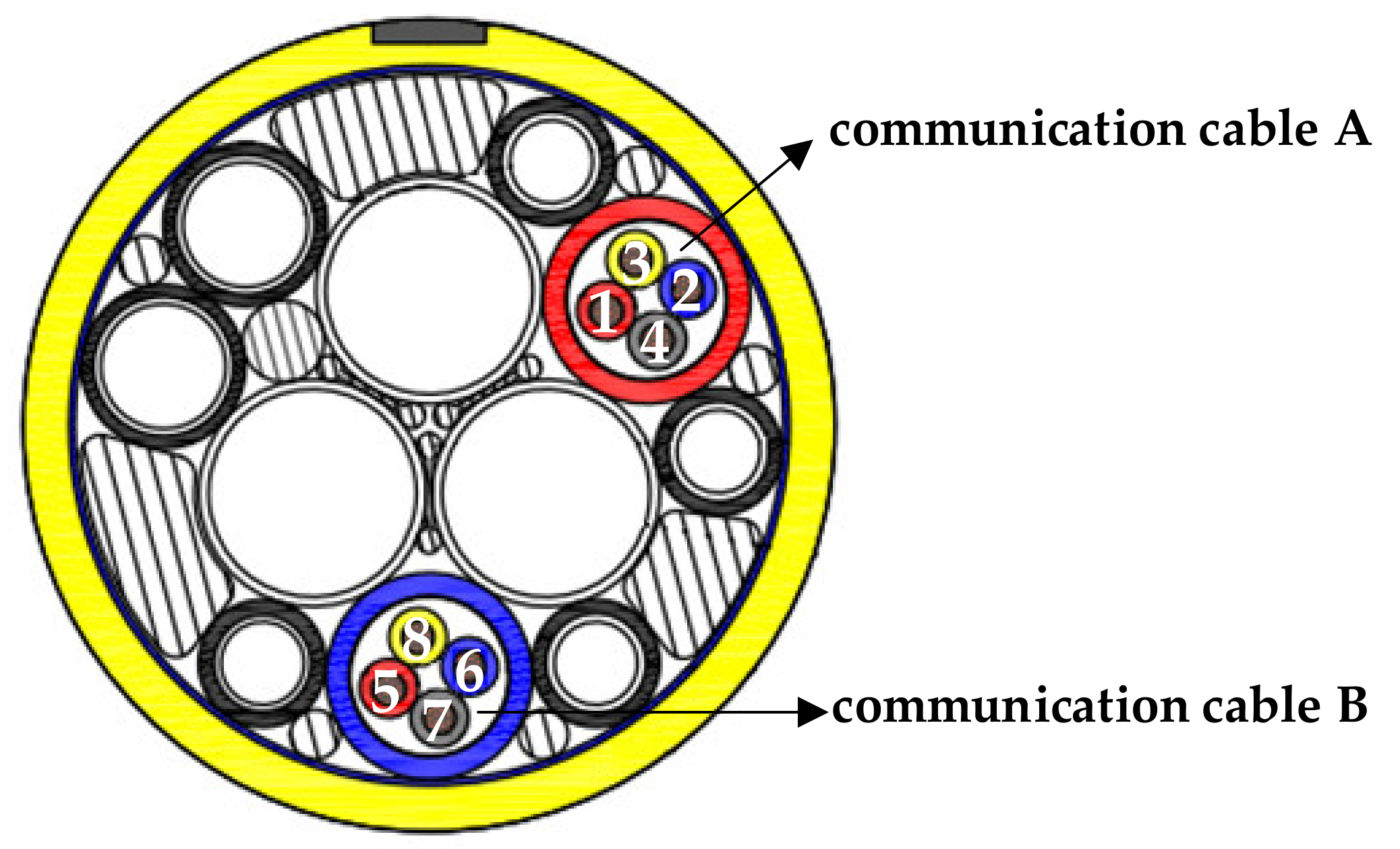
5. Crosstalk Analysis of the Umbilical Cable

The proposed crosstalk model is then used to further study the crosstalk patterns of the umbilical cable. For the umbilical cable shown in Figure 5, the changing patterns of crosstalk between the two communication cables are computed and analyzed. In the numerical calculation, conductors 1 and 2, 3 and 4, 5 and 6, 7 and 8 constitute the circuit loops, respectively, with the same resistance connected to the core conductors in every terminal port, and only one signal source connected to some terminal port in communication cable A. The numerical results are shown in Figure 9 and Figure 10. Figure 9 shows the changing pattern of the far-end crosstalk value over the frequency range from 100 Hz to 30 kHz, where the total cable length is 2 km, both pitch lengths of communication cables are 325.5 mm, and all the terminal resistances are set to 50 Ohm. Figure 10 shows the changing pattern of the far-end crosstalk value over the pitch range of communication cable B from 80 mm to 1800 mm, while the pitch length of communication cable A retains 325.5 mm, the total cable length is set to 10 km, the terminal resistances are all set to 50 Ohm and the source frequency is set to 40 kHz.
From Figure 9, it is observed that, as the frequency increases, the crosstalk value between the two communication cables first increases and then decreases. This phenomenon can be qualitatively interpreted as the combination of electromagnetic induction and skin effect. The higher the frequency, the more pronounced the electromagnetic induction, as a result strengthening the crosstalk value. Meanwhile, the higher the frequency, the more pronounced the skin effect, which means that it is harder for electromagnetic fields to penetrate the metal sheaths, weakening the crosstalk value between the two communication cables. In the relatively low frequency range, the electromagnetic induction is predominant, which results in the increase of the crosstalk value with the increment of frequency. In the relatively high frequency range, the skin effect dominates, leading to the decrease of the crosstalk value with the increment of frequency.
From Figure 10, it is observed that, when the pitch length of communication cable B is one time, three times or five times the pitch length of communication cable A, (corresponding to 325.5 mm, 976.5 mm and 1627.5 mm, respectively), the local maximum crosstalk values are reached. Yet at other pitch lengths of communication cable B, the crosstalk values all decrease significantly compared to the local maximum values. Figure 10 indicates that the crosstalk will be prominent when the pitch lengths of communication cables are odd multiples, which should be avoided in manufacturing.

6. Conclusions

A numerical model and methodology for crosstalk calculation considering the twisted structure of conductors is proposed in this paper to tackle the difficulty in calculating the crosstalk between communication cables in an umbilical cable, by using the discretization method, the transposition technique and the MTL theory. Concretely, the proposed model divides the twisted transmission lines into a certain number of sections. Each section is 1/4 pitch long, and is regarded as a uniform one, which means that there is no twist in any discrete section. The helical topology of the original cable cores is represented with a series of abrupt transpositions at the end of each wire section. Every transposition requires the cable cores to rotate 90 degrees along the helical direction instantly, where four sections just form a cycle of twist. The difference between this discrete model and the actual twisted structures is small. Therefore, this crosstalk model can give relatively accurate predictions. With the chain-parameter matrices and the permutation matrices, the general solutions characterizing the discrete model have been obtained. The special solutions of the specific operating condition are obtained by the numerical calculation with terminal constraint equations. Due to the numerical calculation of electromagnetic field only for one cross section required, the proposed crosstalk model is not computationally expensive. The accuracy of the calculation results of the proposed crosstalk model have been validated by experimental studies. Numerical results on the changing patterns of crosstalk in some umbilical cable show that the odd multiple relation of pitch lengths of cable cores should be avoided for better signal transmission performance.

Author Contributions

Conceptualization, R.C. and S.Y.; data curation, R.C.; formal analysis, R.C.; investigation, R.C.; methodology, R.C.; project administration, S.Y.; resources, R.C. and S.Y.; software, R.C.; supervision, S.Y.; validation, R.C.; visualization, R.C.; writing—original draft, R.C.; writing—review and editing, R.C. and S.Y. All authors have read and agreed to the published version of the manuscript.

Funding

This research received no external funding.

Institutional Review Board Statement

Not applicable.

Informed Consent Statement

Not applicable.

Conflicts of Interest

The authors declare no conflict of interest.

References

  1. Gao, H.; Guo, H.; Sun, K.; Qu, Y.; Guo, Y.; Li, B. Preliminary physical design of subsea umbilical cable for production system. Electr. Wire Cable 2011, 6, 12–16. [Google Scholar]
  2. Li, Z.; Jia, P.; Wang, H.; Zhang, N.; Wang, L. Development trend and active research areas of subsea production system. J. Harbin Eng. Univ. 2019, 40, 944–952. [Google Scholar]
  3. Dutoit, D.; Nikles, M.; Rochat, E. Distributed fiber optic strain and temperature sensor for subsea umbilical. In Proceedings of the Twenty-Second International Offshore and Polar Engineering Conference, Rhodes, Greece, 17–22 June 2012; pp. 349–355. [Google Scholar]
  4. Guo, H.; Guo, J.; Hao, L.; Yuan, J. Electromagnetic interference and shielding analysis of power cables with signal cables in composite umbilical cable. Electr. Wire Cable 2020, 4, 1–3. [Google Scholar]
  5. So, Y.B.; Gyu, H.K.; Jung, K.S. Thermal and electromagnetic characteristics for cross-sectional design optimization of the integrated production umbilical. IEEE Trans. Ind. Appl. 2017, 53, 1598–1604. [Google Scholar]
  6. Salles, M.B.C.; Costa, M.C.; Filho, M.L.P.; Cardoso, J.R.; Marzo, G.R. Electromagnetic analysis of submarine umbilical cables with complex configurations. IEEE Trans. Magn. 2010, 46, 3317–3320. [Google Scholar] [CrossRef]
  7. Charles, J.; Philippe, B.; Michel, D.; Isabelle, J. Advanced modeling of crosstalk between an unshielded twisted pair cable and an unshielded wire above a ground plane. IEEE Trans. Electromagn. Comp. 2013, 55, 183–194. [Google Scholar]
  8. Clayton, R.P.; Jack, W.M. Prediction of crosstalk involving twisted pairs of wires—Part I: A transmission-line model for twisted-wire pairs. IEEE Trans. Electromagn. Comp. 1979, 21, 92–105. [Google Scholar]
  9. Clayton, R.P. Lumped-Circuit Approximate Characterizations. In Analysis of Multiconductor Transmission Lines, 2nd ed.; Wiley: New York, NY, USA, 2008; p. 313. [Google Scholar]
Figure 1. Cross section of the communication cable consisting of conductors 1 to 4.
Energies 15 03501 g001
Figure 2. The simplified structure of the four twisted conductors.
Energies 15 03501 g002
Figure 3. The abrupt transposition model of the four twisted conductors, where V ^ i ( z ) ( i = 1 , 2 , 3 , 4 ) represents the voltage phasor of each conductor at axial position z, I ^ i ( z ) ( i = 1 , 2 , 3 , 4 ) represents the current phasor of each conductor at axial position z. The four twisted conductors marked as ① to ④ are all used as signal conductors, and the conductor ⓪ represents the reference conductor.
Energies 15 03501 g003
Figure 5. Schematic diagram of the cross section of the prototype umbilical cable.
Energies 15 03501 g005
Figure 6. Reference conductors of the finite element model.
Energies 15 03501 g006
Figure 7. Finite element mesh of the cross section of the umbilical cable.
Energies 15 03501 g007
Figure 8. The umbilical cable used in the experiment.
Energies 15 03501 g008
Figure 9. The changing pattern of the far−end crosstalk value versus frequency.
Energies 15 03501 g009
Figure 10. The changing pattern of far−end crosstalk value versus pitch length.
Energies 15 03501 g010
Table 1. Comparison of the calculated and measured crosstalk voltages on the impedance.
100 kHz
measured magnitude of voltage/V33.500
calculated magnitude of voltage/V31.065
Publisher’s Note: MDPI stays neutral with regard to jurisdictional claims in published maps and institutional affiliations.

