1. Introduction
Nuclear power is generated by a small amount of fuel, as related to other non-renewable energy sources. The volume of waste formed in this process is comparably small. However, a great part of the nuclear waste is highly radioactive and must, therefore, be managed with special precautions. Certain non-nuclear power countries, including Poland, exploit nuclear research reactors. Recently, several of them have also decided to construct or buy reactors which supply heat for the industrial processes. These are Small Modular Reactors (SMRs) and High Temperature Gas Cooled Reactors (HTGR). Poland is one of such countries. In addition to nuclear energy, radioactive waste is generated from the radioactive materials used in nuclear medicine, agriculture, research, manufacturing, non-destructive testing, and mineral exploration (even by the coal mines). The latter, however, are mostly intermediate- or low-level waste.
Poland has no nuclear power plant yet. However, in January 2014, the Government decided to start the Polish Nuclear Power Program (PNPP) [
1]. At the same time, the use of the high-temperature gas-cooled reactor (HTGR) technology to supply Polish industry with heat based on construction of certain small, 200–350 MWt, HTGRs is being considered [
2]. Furthermore, Synthos Green Energy company, for the same purpose, announced intention to buy the first BWRX-300 small nuclear reactor [
3].
Given all the above facts, as well as formation of the radioactive waste from the nuclear medicine, science, and industry, common knowledge of methods used in the waste management is an important problem.
Radioactive waste is defined as solid, liquid, or gaseous material containing or contaminated with radioactive substances in concentrations or activities exceeding the limit values settled by national regulating bodies, the use of which is not anticipated or considered [
4]. Besides by nuclear power plants, it is produced by the scientific laboratories, nuclear medicine centers, and the non-nuclear industry that apply the radioactive sources. As the radioactive waste emits the ionizing radiation, it causes a particular risk to human health and to the environment [
5].
Basing on the radioactivity concentration of radioactive isotopes present in the waste, it is classified as:
- ✓
low active,
- ✓
medium active, or
- ✓
highly active.
All the above categories of radioactive waste can be divided into subcategories, according to the half-life of radioactive isotopes present in this waste.
The criteria for dividing radioactive waste into categories and subcategories are presented in
Table 1 [
6,
7].
The spent nuclear fuel and products of nuclear fuel production and processing plants intended for disposal are classified as highly active radioactive waste.
Radioactive waste of low and intermediate level (LLW and ILW, respectively) from nuclear power plants is a wide range of items and materials, ranging from rubber gloves and protective covers for footwear (LLW), through wastewater from cleaning procedures of water from cooling circuits of the power plant and other solid intermediate level waste (ILW). They are akin to industrial and medical waste that people have many years of experience with. Therefore, most of the industrial forms of treatment and storage of municipal waste can be applied to radioactive waste. Unlike other hazardous industrial waste materials, hazard menace of the radioactive waste that results from its radioactivity decreases over time. Therefore, the management of low- and intermediate-level radioactive waste, especially if they have a small mass, often consists only of the effective conditioning, shielding and storage for several decades (in the UK, one hundred years) in specially constructed bunkers.
Although mass of the HLW is only 3% of the total radioactive waste, it generates about 95% of the total radioactivity of the waste. As a result of high decay heat of high-level waste (HLW) (>2 kw/m3), it increases its temperature and requires not only shielding but also cooling.
We can distinguish two types of HLW:
- ✓
Used fuel that has been accounted as waste intended for storage when removed from the reactor. Until now, European countries had a duty to secure their safe, long-term disposal in their territory. Recently, however, there has been an initiative to make a common disposal place for entire fuel elements. Currently, the operation is performed in special dry storage casks and does not require any additional procedures until final disposal facility will be developed
- ✓
The waste formed in the course of the processing of spent fuel. Such processing is conducted only in two plants in Europe (not counting Russia), and the resulting high-level waste is returned to the country that provided the fuel for processing. This type of HLW, after protection against leaching the radioactive matter, in the vitrified form may be sent for the definite storage. In addition, regardless of the type of reactor, spent parts (such as reflectors, moderators, or housings) also are accounted as HLW. If they are made of graphite or carbonaceous materials, their mass can be reduced thermally and sent to storage as low-volume HLW. Non-combustible materials shall be stored in their entirety, cut into smaller fragments, or decontaminated.
Currently, each country that orders the reprocessing of spent nuclear fuel is required to accept the generated waste on its territory and dispose of it permanently. However, efforts are being made to build a common European repository for spent fuel and high-level radioactive waste.
Treatment of the nuclear and radioactive waste, aimed at preparing them for safe disposal, consists of the withdraw of any part that can be recycled or in the reduction of the amount of contaminants or hazardous substances contained therein. As a result, however, most of these processes generate medium- and low-active secondary waste, mainly solid residues of waste gas treatment, distillation condensates, and decontamination solutions. This secondary waste may be either recycled in the consecutive treatment processes (with possible wastewater release), or added to the nonnuclear radioactive waste and prepared for storage or disposal. The general rule of these processes is: the less radioactive waste needs to be managed, the better.
In light of what has been said above, the methods of preparing nuclear waste for storage and disposal do not differ from those used for non-nuclear radioactive waste. The most widely used treatment techniques are: incineration of solid waste and evaporation of liquid waste. As soon as the waste has been prepared in a form that can be stored or disposed, further procedures of conditioning should be applied to slow the release of radionuclides from the disposed waste package into the environment. To condition waste for disposal, it is usually encapsulated or solidified in bitumen, glass or synthetic rock into special containers. All these thermal processes will be presented in the following text.
2. Thermal Treatment of Radioactive Waste: Advantages and Disadvantages
Thermal treatment of waste is a term given to any treatment technology that involves high temperatures in the processing of the waste feedstock [
8]. In the common sense, as applied to the household and municipal waste, this is the open burning (combustion) with emission the products of burning directly into the open air. In that meaning, open burning is an invasive process for the environment because of lack of control of the pollution and the possibility of the surroundings’ contamination. Thus, open burning is not used for treatment of the radioactive waste, and the combustion is accompanied by passing the flue-gas through an advanced filtering system.
The thermal treatment of radioactive waste is used to either to reduce its total mass, destroy hazardous organic substances, or to stabilize its non-combustible, hazardous components in leach-resistant matrices (e.g., glass, ceramic, or synthetic rock). It is one of the methods with the greatest potential for both efficient decrease of mass and for protecting waste against leaching by different water streams.
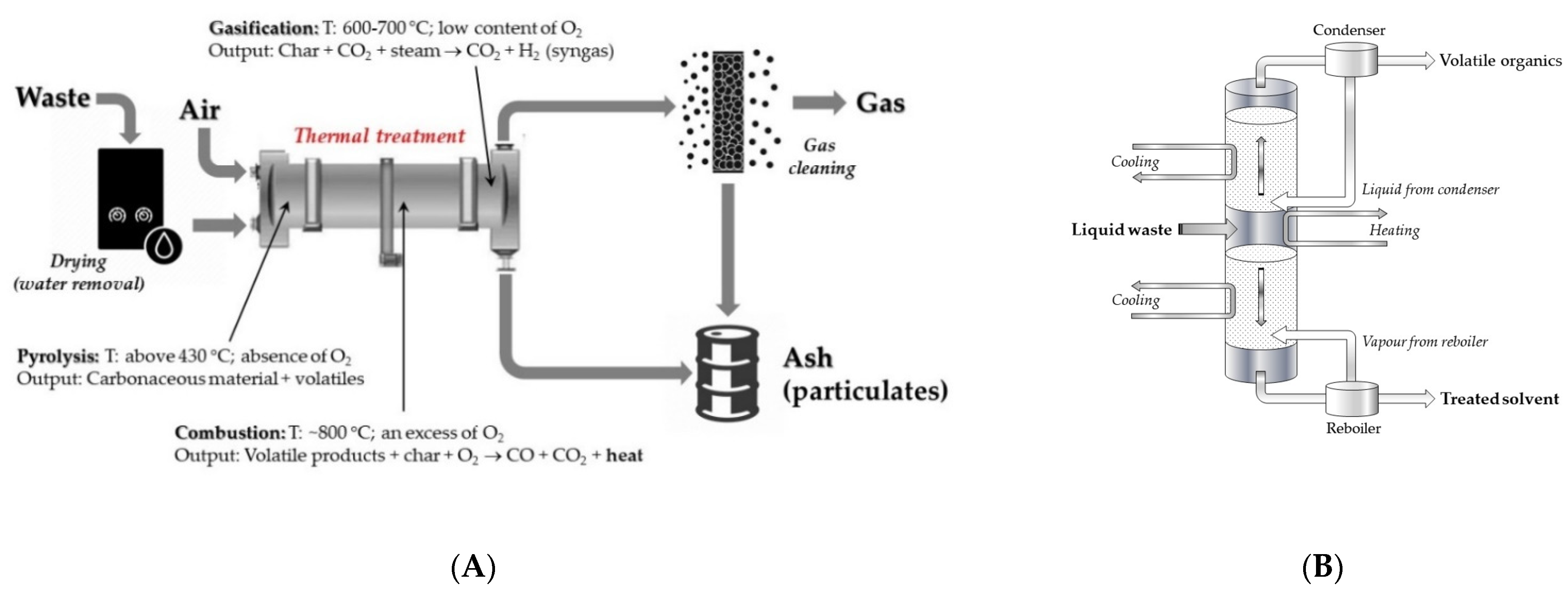
Into the mass-reduction group of methods, in addition to the commonly recognized process of combustion, it is necessary to mention gasification, incineration, and pyrolysis. In addition, distillation, a method of separating toxic components of liquid solutions, should be accounted for in this group of methods. Schematic presentation of the mass reduction methods is shown in
Figure 1. In more detail, these methods will be presented in a Part 3.
Additionally, in the mass reduction methods, thermal treatment may be also used for improving the form of waste to be deposited, or at least its homogeneity. Such processes, as bituminization, vitrification, or forming a phase resembling some natural minerals (Synroc process, used for treatment of high-level waste (HLW)), allow for the production of solid solutions, mainly highly active, of radioactive waste which is extremely resistant to leaching of harmful components. Because of their high cost, they are not, at present, applied to the non-radioactive waste. The waste immobilization methods will be introduced to the readers in a Part 4.
To make it easier for readers,
Table A1 and
Table A2 in the Appendix present the main feature of treatment of different types of radioactive waste and summarize their applicability.
3. Thermal Methods for Reduction of the Waste Mass
The most recognized thermal treatment technologies used for mass reduction of waste are advanced open burning (combustion, incineration), pyrolysis, and/or gasification.
Similar to the combustion, gasification and pyrolysis of waste materials are also not new concepts since, for a long time, they have been used to produce fuels (e.g., charcoal, coke). Even though several large facilities for radioactive waste treatment have been built by now and operate in numerous countries, the following other pilot plants are in the early stages of development.
In the case of liquid radioactive waste, evaporation/distillation techniques are often used for purification and removal of solvents with high decontamination factors and for the production of concentrated radioactive salts as bottom residues. In the case of aqueous solutions, the former is suitable to be released into the environment. The decontaminated extractants, in turn, may be re-used for the spent fuel reprocessing. The non-volatile, small mas solid bottom residues may be sent to their storage place.
3.1. Calcination
The term calcination refers to an industrial process carried out without access to air or oxygen at an elevated temperature. The temperature should be, however, lower than the melting point of the solid material. Finally, calcination leads to removal of the volatile substances present as impurities.
Calcination is mainly carried out to remove volatile components of the waste material. This process is defined as heating the matter in the absence or presence of strongly limited air or oxygen to a temperature below its melting point. The process is mainly performed to remove volatile impurities. These pollutants should include, but are not limited to, carbon dioxide, inert gases, and ammonium ions [
9]. The process takes place in a cylindrical reactor (calciner) under strictly controlled conditions. Off-gas is purified and released in the atmosphere, while solid calcine is gathered, stored, or processed.
Since the very beginning of implementation, of the calcination method, different variants of the process were tested. The main are methods used for the radioactive waste treatment are pot [
10], fluidized bed [
11], and rotary-ball kiln [
12]. The product from any of them, in the post-calcination stage, can be transformed into a glass-like material or diluted in the insoluble matrix materials with the aim of decreasing leaching of the radioactive components of waste by water and growing its thermal conductivity.
3.1.1. Pot Calcination
The oldest method of calcination is a pot process. The pot-calcination process consists of simply feeding the radioactive waste in the evaporator for concentration and for withdrowing the volatile components (e.g., nitric acid resulting from the reprocessing of nuclear fuel) are withdrawn by steam. Then, the concentrate is fed into a calcination vessel for thermal decomposition of dissolved solids, usually at temperatures below 900 °C, converted into a solid cake, and, finally, calcined. After finishing calcination, the container with the solidified content is withdrawn from the system, closed, and sent for storage (temporary or final).
The pot calcination process is simple, easily adaptable to manage different types of waste formed in nuclear fuel processing (e.g., Purex process used for the separation and purification of uranium and plutonium from the spent nuclear fuels, or Darex process applied for the recovery of uranium from stainless steel containing reactor fuels), and produces a small amount of off-gas which may be re-processed or released into the environment [
13]. The batch nature of this method limits its application, however, to the large-scale, and controlling its quality is more difficult than in other methods.
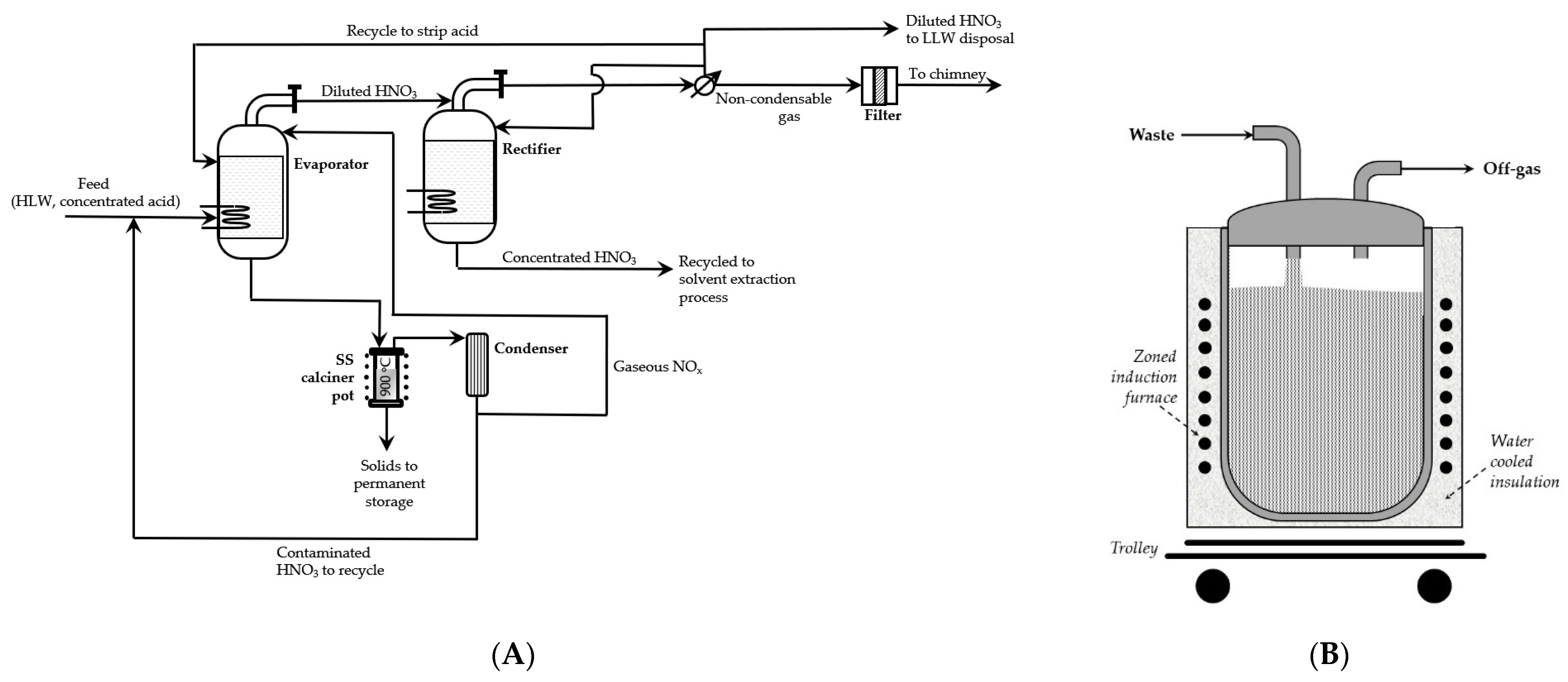
One of the first industrial installations operated in the Oak Ridge National Laboratory from 1962 to 1965 as the Waste Solidification Engineering Prototype (WSEP) facility at Hanford. The scheme of this installation is presented in
Figure 2, on the left-hand side.
In the process, liquid radioactive waste was evaporated as much as possible without separation of solids. It was then transferred in batches to a vessel, usually called “pot”, made of stainless-steel pipe, and heated in a zoned furnace. When water and the volatile solvents were evaporated, at temperature of 700–900 °C, the calcined crust was formed on the sides and bottom of the pot. The process was continued until the container was filled in about 90%. At the end of calcination, the pots were removed from the system, sealed, tested for their thermal, radiation, and mechanical stability, and sent to a dry, geologically isolated environment, such as a salt mine, for final storage. Hanford’s research was also conducted with ring vessels [
14].
3.1.2. Rotary Kiln Calcination
The rotary kiln furnace is equipped with a rotating tubular compartment that keeps the waste moving. Thus, it allows waste to evaporate for facilitate calcination, incineration, or pyrolysis.
The whole technological line equipped with the rotary kiln consists of 3 main parts:
- ✓
the chamber to perform thermal process,
- ✓
the compartment for recovery of energy, and
- ✓
installation for treating the flue gas.
The rotary kiln reactor usually needs, using supplementary combustion space, to ensure perfect destruction of the waste components. The primary chamber is used for the approximate incineration or pyrolysis of the solid radioactive waste into gases. The process running in the gas phase is completed in the secondary chamber. Generally, both the primary and secondary reactors are supplied by the independent burning fuel systems.
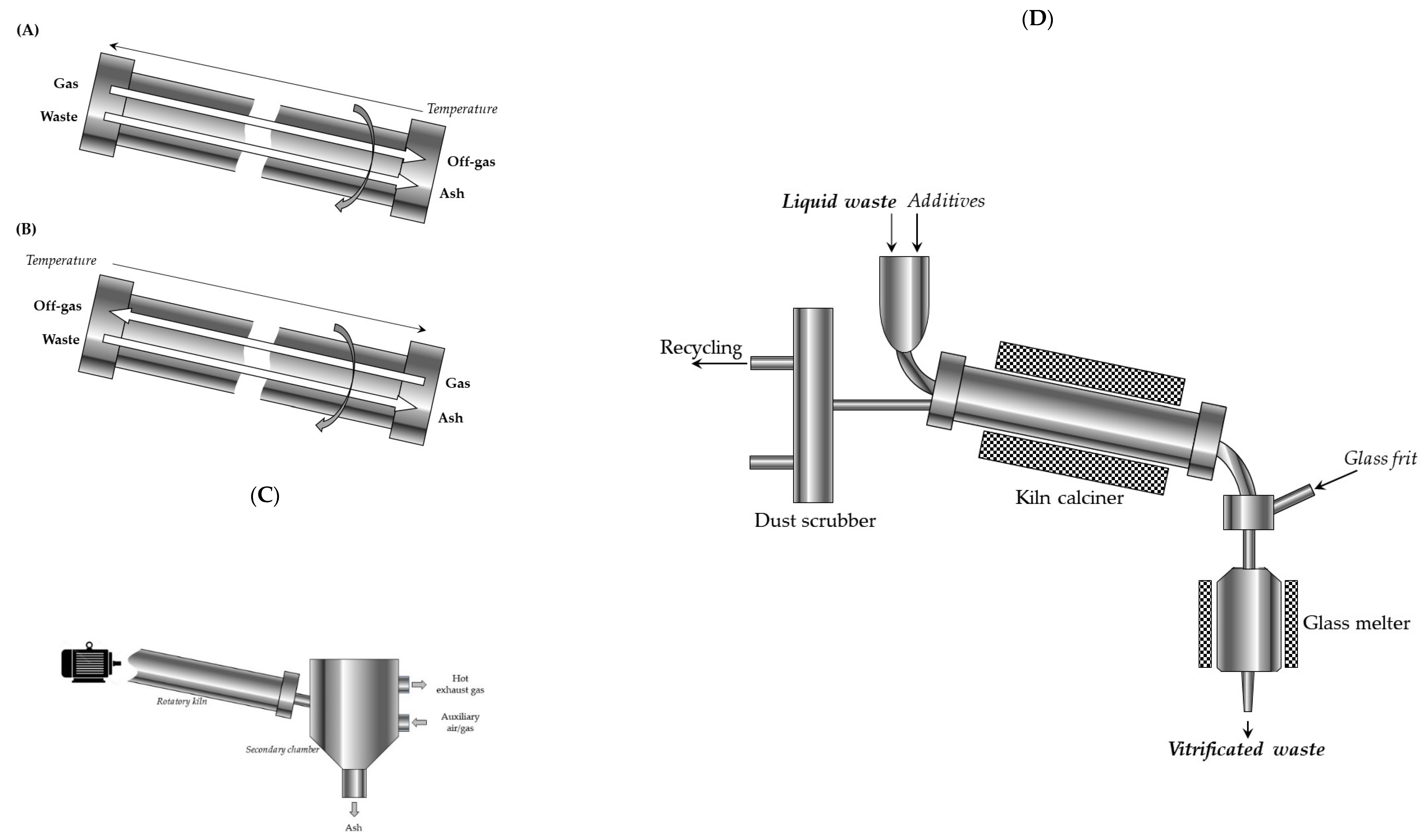
There are two diverse types of rotary kiln: co-current rotary kilns and counter current rotary kilns (
Figure 3).
In the counter current rotary kiln, waste and the flue gas (in the case of the pyrolysis or the combustion) flow in opposite directions. In the kiln, thermally-treated solid waste moves by the rotary motion and by gravity, in accordance with the direction of decline of the furnace.
In the co-current rotary kiln, both flue gas and waste relocate, also by the rotary motion supported by gravity, from the high end to the low end of the chamber.
Depending on the design of the reactor, waste movement through this horizontal cylindric reactor is supported by an internal auger, whereas the reaction gas is injected by multiple valves placed linearly along the kiln.
Investigation of rotary-kiln calcination of high-level radioactive wastes was started at Brookhaven National Laboratory in 1955 using mineral ion exchanger media [
15]. As some problems, however, with using a rotary kiln for treatment of a highly active waste were revealed, they have been resolved in the French vitrification plant at Marcoule (AVM) [
16]. The full-scale AVM facility used the calcination rotatory tube inclined at 1.5 degrees, rotating at 0.5 revs s
−1, heated to about 500 °C. A special metal rod moved inside the tube to break down calcine to powder which flowed directly into the vitrification melter. Nominal efficiency of the process was about forty l h
−1 and comprised about 2.l h
−1 recycle from an off-gas wet scrubber [
17].
3.1.3. Fluidized Bed Calcination
The fluidized bed calciners have been constructed to replace the kiln calcination and have been commercially available since the early 1960s. Calciner with the fluidized bed offers better results of calcination of fine powders, especially as compared with the rotary furnace method or the vertical shaft furnace.
A fluidized bed is formed when gas flows upwards through a layer of powdered material: particles of the material are lifted by the ascending hot air; thus, they behave similarly to the liquid.
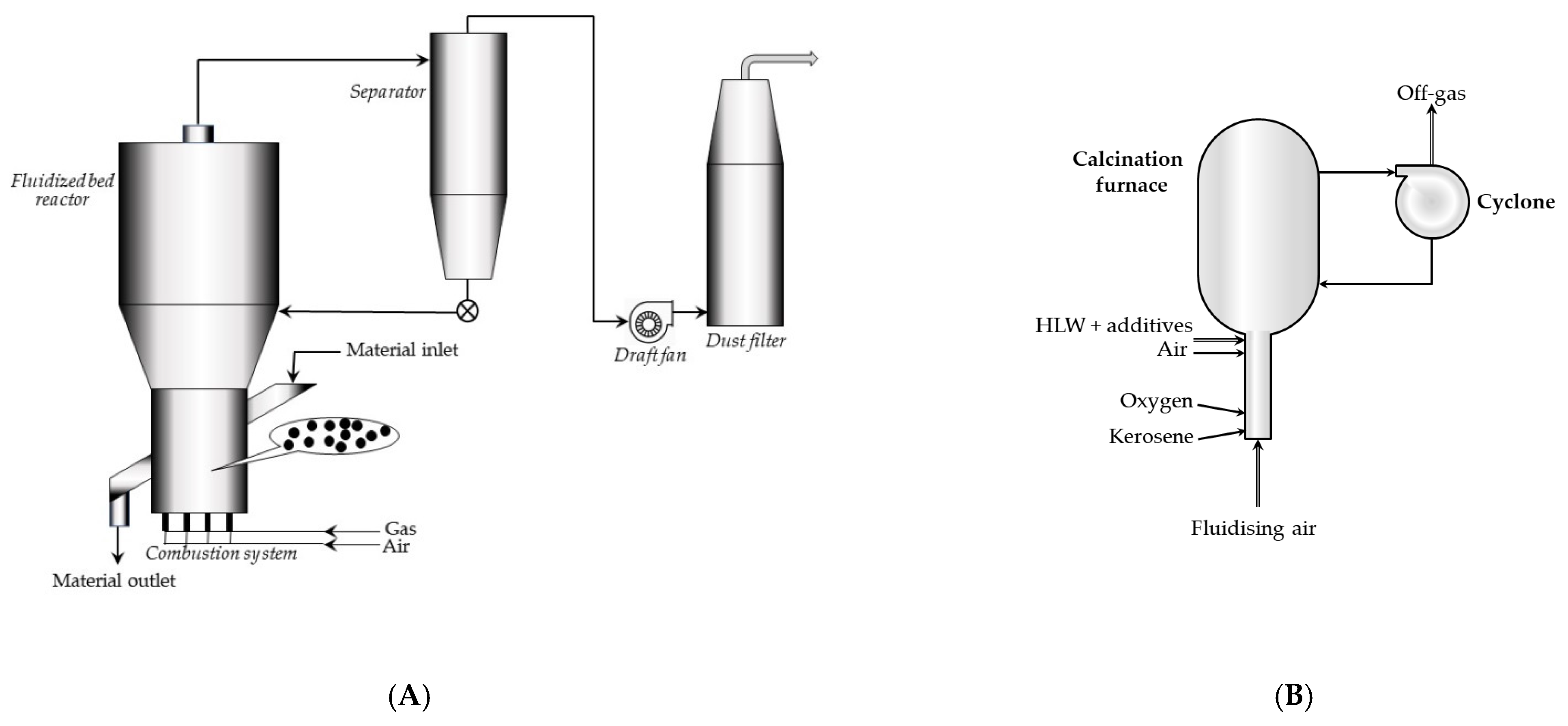
A fluidized bed system is a closed setup formed by a fluidized chamber, a split bottom plate, and a hot air chamber. Construction of the fluidization chamber and the materials used depend on the materials to be calcined, as well as on the calcination temperature. The powdered calcinated material forms the fluidized solution with the high-speed passing hot air (up to 1000 °C). After a solid/air reaction (calcination), the powder is discharged from the system (
Figure 4A,B).
Fluidized bed calciners are often used for HLW solutions, which should be dried and calcined. The so-called fluidized bed, i.e., a layer of powder material, is driven by a flowing oppositely from gas (e.g., a stream of air). Aluminium oxide and/or silicon oxide of a certain grain size are sometimes added as the fluidized-bed inert material. These inert bed particles may be used to an advantage as an addition to the final fixation product.
The fluidized-bed space may be heated to a temperature of 500–600 °C, either indirectly using electrical coil or any other heating medium or directly by combustion of the liquid or gaseous fuel in the bed. Heating by means of an external furnace may sometimes result in a big loss of certain radioactive pollutants (e.g., ruthenium or radiocesium). Heating carried out by burning kerosene within the bed prevents this problem.
The dried calcine accumulates at the bottom and is transported to the next operation. Finer particles are separated from gases and aerosols by cyclones.
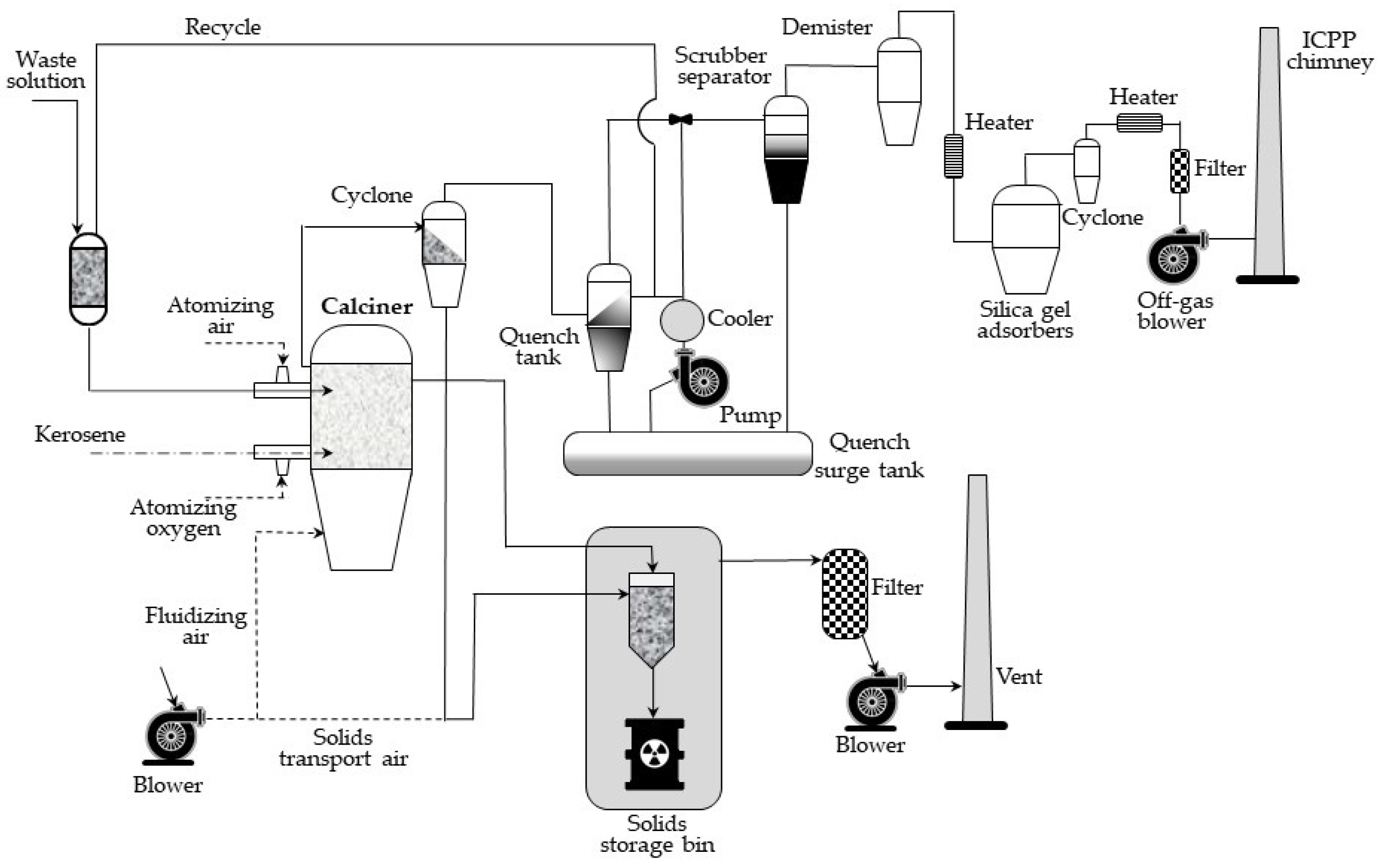
The flow diagram for the waste calcining facility (WCF), installed in early 1970s in Idaho Chemical Processing Plant (ICCP), is shown in
Figure 5. The main element of the process is an about 1.2 m in diameter calcination vessel, in which radioactive aqueous waste is continuously sprayed, and a fluidized bed using pneumatically delivered air. Ignition is spontaneous at temperatures above 335 °C in the presence of nitrates. After the start-up, the wastes are calcined at temperatures in the range of 400–500 °C during routine operation. In the fluidized bed, water flows out, and metal salts are converted into oxides or fluorides and settled as growing layers on spherical grains of the bed. These solid grains are continuously removed from the calcination container to maintain a constant height of the bed and then pneumatically transported to the steel storage tanks, stored near the calcination plant [
20,
21].
The waste gases, in turn, when leaving the calcination vessel, pass through a dry cyclone, where most of them, taken away with gas fine particles, are separated and pneumatically transported to the same storage tanks.
The fluidized bed calciners are advantageous for their continuous operation, the possibility of automated control, and their high capacity. The disadvantages, in turn, include the formation of fine particulates and aerosols.
3.2. Incineration (Combustion)
The combustible components of both the radioactive and industrial waste may be treated by the incineration method to reduce volume of waste intended for storage. It is an exothermic reaction of oxidation using oxygen at elevated temperatures to destroy organic material. Frequently, the incineration of waste itself provides sufficient heat to continue the reaction. In other cases, however, it is necessary to use a supplemental fuel to provide energy necessary for continuing oxidation. Most frequently, natural gas or oil are used.
At present, the method is applied in many countries (e.g., Austria, Belgium, Canada, France, The Netherlands, the Russian Federation, Slovakia, the UK, and the USA) [
23]; however, it must be accompanied by processes that ensure that the gas emission limits are fulfilled. In the case of radioactive waste, incineration is used for treatment of LLW arising from the nuclear power plants, fuel production facilities, research and nuclear medicine centers, and waste treatment facilities.
Following the separation of non-combustible constituents, the waste is incinerated in a specially designed kiln at temperatures up to around 1000 °C. The gases and fumes produced during incineration are treated and filtered prior to emission into the atmosphere in accordance with the current purity standards. After incineration, the resulting ash, which contains the radionuclides, may require further conditioning, such as bituminization or vitrification, prior to disposal. Overall, volume reduction factors of up to around 100 are achieved, primarily for LLW, depending on the density of the waste. Therefore, it should be considered as a tool for decreasing mass of the waste suitable for disposal and not as a method of ultimate disposal on its own [
24].
Several different incineration technologies are available, some of them being similar to these used for calcination. Among the most popular, probably, are [
25]:
- ✓
Incineration in an excess of air, being a one step process. The significant excess of air added (50–75%) results in considerably large carry off particulate matter in off-gas, which is of relatively low quality.
- ✓
Controlled air incinerators reach near complete combustion of the waste using several combustion chambers in sequence. The waste is at first burned at 600–800 °C, at near stoichiometric air ratios. Next, the gases are burned at 1000–1200 °C in the secondary chamber with an excess of air. In this method, off-gas is of good quality.
- ✓
Depleted air incinerators use of two consecutive combustion chambers. In the first one, waste is thermally decomposed in a depleted oxygen atmosphere. Next, formed gas is mixed with an excess air and, after, burned in the second chamber. This process forms off gas of good quality.
Preparing such a brief review is difficult, however, to characterize other known variants of incineration.
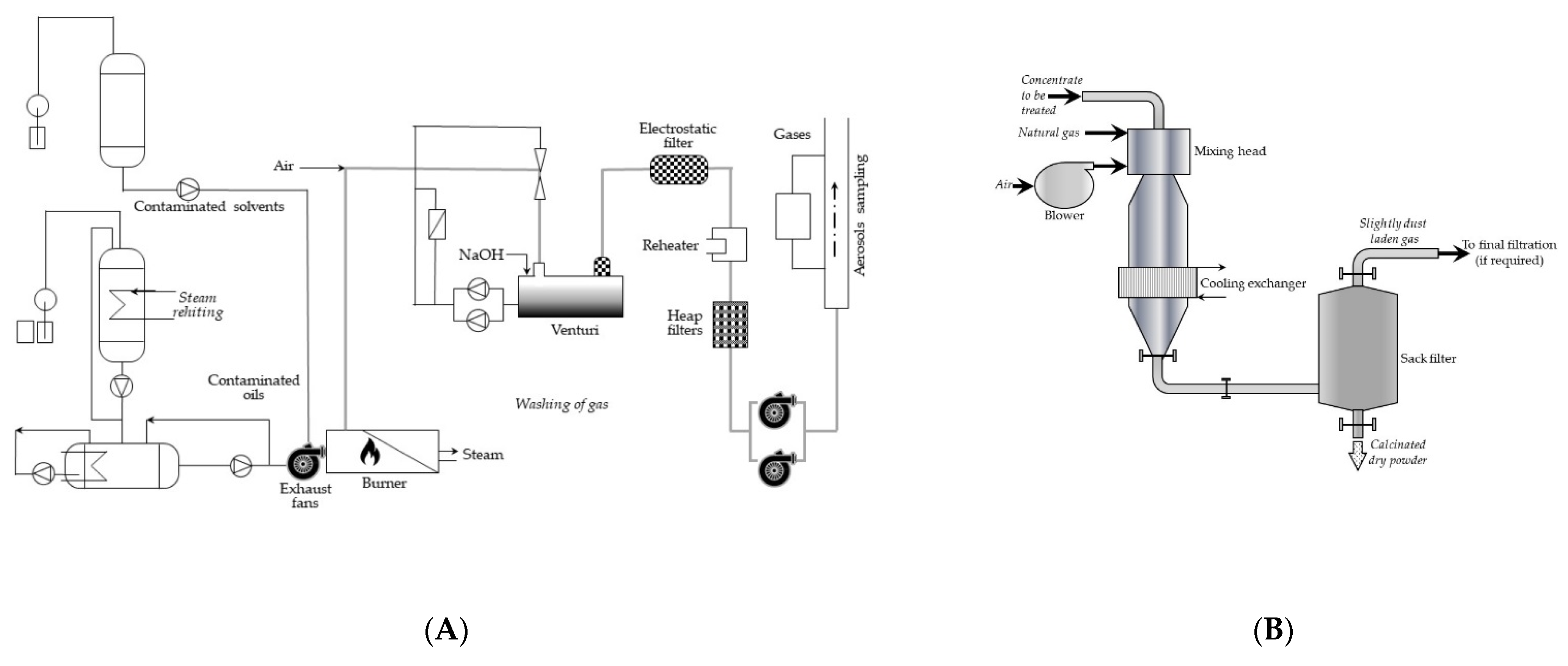
Let us look at only one of the incineration plants, Pierrelatte, in service since November 1987 at Compagnie Générale des Matières Nucléaires (COGEMA, France). The process diagram is shown in
Figure 6A, and the simplified scheme of the calciner skeleton is shown in
Figure 6B.
In brief, the incinerator was a fixed horizontal boiler with smoke tubes equipped with an oil/solvent dual fuel burner. The furnace outlet temperature was 900–1000 °C. The combustion gases were cooled in the smoke tubes to 250–300 °C. The off-gases were washed by a two-stage venturi with a soda solution to neutralize the acids formed during combustion and supplement dust extraction from the smoke. On leaving the washing plant, the gases were purified in the unit, consisting of a demister (for extraction of droplets from the gases), heating devices (to about 80 °C, to limit the risks of condensation during extraction), and the electrostatic filters of radioactive particles. The installation operated in 100-h cycles operated by teams of 2 persons.
It is also important to mention the wet oxidation process, also called wet combustion, wet incineration, or air wet oxidation [
25,
27]. The process is carried out by combustion oxidation at a temperature above 120 °C, but below 350 °C, in the presence of water. It is used for treatment of hard-to-dehydrate solid waste or aqueous sludge that contain a few percent of water. Usually, if the process is carried out in the proper conditions (temperature, pressure, appropriate reaction time and enough concentration of oxygen or air), any wanted degree of oxidation can be reached.
Wet air oxidation, contrary to the conventional flash combustion, does not require preparatory removal of water or drying waste. Water content in this process can even be above 99%, while, in conventional combustion, it should be kept below 75%, or special additives for facilitate burning should be added. Despite the “quenching” properties of the reaction, water is an essential substrate for wet air oxidizing.
Another crucial difference of the flameless oxidation of organic matter is low temperatures of the process, from 150 °C to 200 °C, compared to 800 °C to 1500 °C in a conventional combustion. Pollution of the feeding air should be carefully controlled because wet oxidation takes place in water at relatively low temperatures, and neither fly ash nor dust, sulfur dioxide, or nitrogen oxides should be released.
A full-scale wet oxidation system using air was operated, e.g., by Ontario Hydro in the mid-1990s to process EDTA-based boiler chemical cleaning solutions from nuclear power plants [
27].
Coming to an end, the advantages of the incineration process are [
26]:
- ✓
simplicity of the equipment whose “drying head” was the same, whatever the type of application,
- ✓
highly compact units,
- ✓
lack of the moving mechanical parts in direct contact with the products,
- ✓
easy maintenance,
- ✓
low thermal inertia, and
- ✓
rapid, uniform calcination, giving a fine regular granulometry of the secondary waste (about 2 to 10 microns).
3.3. Pyrolysis
Pyrolysis is used to decompose the organics containing waste in the absence of air. The process generates oil products, heavy residues, and combustible gas. The latter may be used for generation of energy. The operating temperature for pyrolysis (500–550 °C) is markedly lower than for air incineration. At these temperatures, the problem of presence of the corrosive species is not as significant as in the case of incineration. For example, generated phosphorus oxides are removed as the readily formed stable inorganic phosphates. In addition, at the lower temperatures and reduced oxygen amount, volatile species, such as ruthenium and caesium, are largely retained within the pyrolysis reactor. Furthermore, the scale of pyrolysis installations is more flexible than incineration plants [
24].
Today, pyrolysis draws attention due to its easy adjustment to production of solid, liquid, and gaseous products in different proportions simply by changing such parameters as temperature or heating speed [
28].
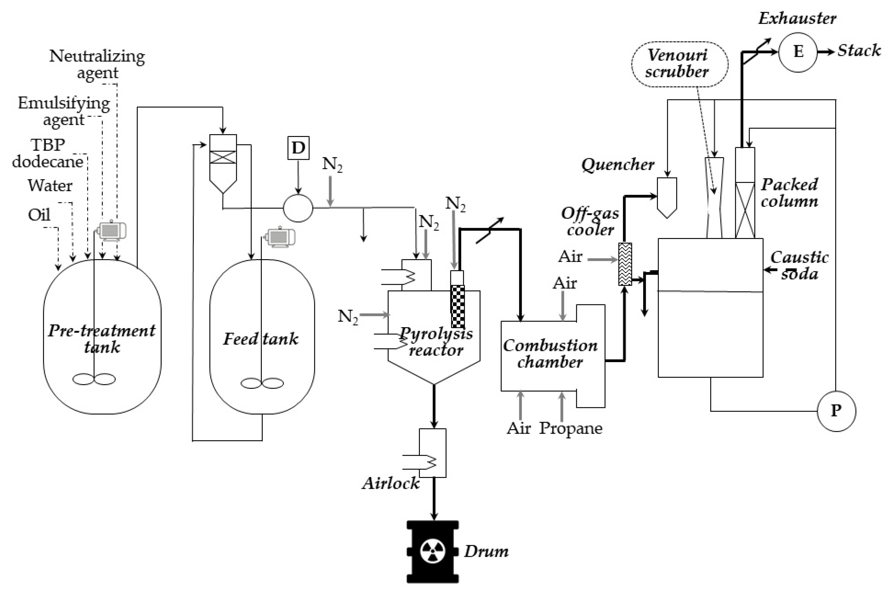
In short, as an example, in
Figure 7, we present details of the pyrolysis process conducted in the pyrolysis pilot unit at the nuclear fuel reprocessing plant at La Hague (France) [
29]. The 3 kg/h TBP (tri-n-butyl phosphate, extractant used for treatment spent nuclear fuel) is fed to a stirred pebble ball pyrolysis reactor [
30]. The reactor bed is kept at high temperature (400–500 °C) by heaters on the walls of the reactor, and the balls are made of carbon steel. To prevent any reaction with air, the reactor is filled with nitrogen.
Contact of the emulsion with the heated balls causes the water and the diluent to evaporate, and the TBP to react with magnesium hydroxide, yielding butene, some butanol, and various magnesium phosphates. Due to the pyrolysis, the feed is split into a gaseous stream and ashes (which are a mixture of magnesium oxide and phosphates). The ashes, through a cooled to room temperature hopper, are mixed with concrete, and batch grouting is performed. The resulting grout is poured into drums.
The filtered off-gas from pyrolysis, in turn, enters a combustion chamber, where it is burned at around 900 °C (forming a mixture of carbon dioxide, nitrogen, oxygen, and steam) and, after cooling, rinsing, and filtering, is released to the environment.
The main advantage of pyrolysis is its lower operation temperature than in standard incineration [
25,
31]. Similar to incineration, pyrolysis is usually applied to a wide range of solids and liquids and provides great reduction in the waste volume and mass. The relatively low temperature of pyrolysis reduces the problem of corrosion of the construction material, as corrosive phosphorous oxides are converted into relatively inert inorganic phosphates and not to phosphoric acid. The process produces fuel with high heat-generating value for commercial purposes, so, e.g., generated carbon, can be used as a fuel in combustion, just as coal, and has commercial value. The capital and operating costs for the equipment resemble those for an incinerator.
However, the specialized pretreatment devices necessary for some types of waste, e.g., for plutonium contaminated materials (PCM) or highly contaminated ion exchange resins, can significantly increase the capital and operating costs. In addition, produced ashes may contain significant amounts of heavy metal, depending on their content in the waste to be processed. The latter are accounted as dangerous waste which must also be disposed. The final waste product is often not as homogeneous as that of a conventional incinerator. Furthermore, an air purification installation is necessary to further treat flue gases from the pyrolysis.
3.4. Distillation and Evaporation (Volatilization) of the Radioactive Waste
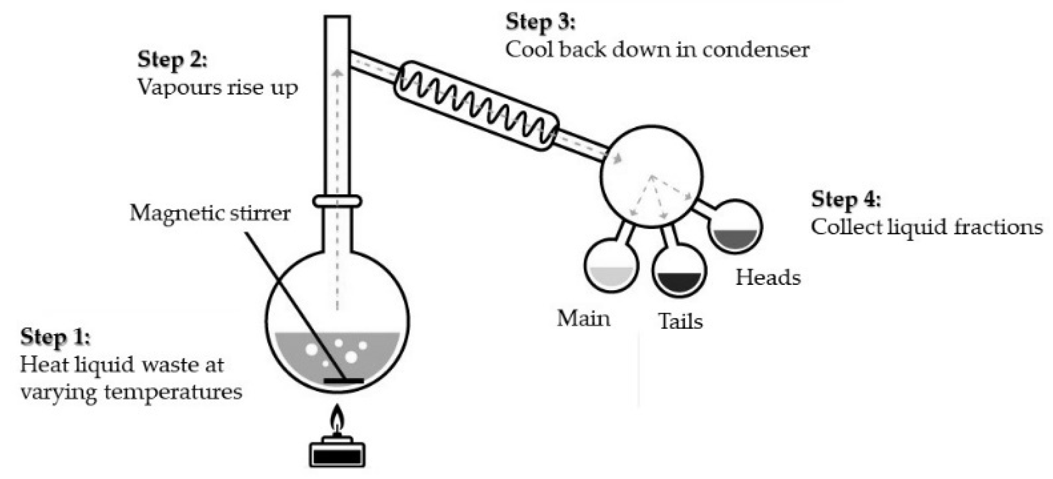
Distillation of the radioactive waste on a semi-industrial scale is often used for the pre-treatment of liquid scintillating cocktails or other organic solvents (e.g., kerosene). Due to this process, it is possible to significantly reduce the volume of liquid waste since the radioactivity emitters are generally concentrated in the residue [
32]. The retrieved organic solvent (distillate) can be useful as a solvent of the technical grade or as fuel for an incinerator. The sludges formed can be, in turn, incinerated or immobilized for storage and disposal. The laboratory scale apparatus for a simple batch distillation is shown in
Figure 8 and presents an idea of the process. Since the basic chemistry course takes place at each university faculty, in this work, we neglect a more detailed description of the process.
It should be stressed that distillation is a simple and well-known process, and operators require only limited training. The process is cost effective, especially if valuable solvents are recovered and reused.
Simple distillation is often used for the treatment of spent liquid scintillation cocktails (frequently used for determining content of
3H and
14C radionuclides and, to a lesser degree, of
125I,
32P, and
35S) and for different waste liquids containing organic solvents [
33].
At the Instituto de Pesquisas Energéticas e Nucleares (Institute for Energy and Nuclear Research, IPEN, Brazil), a 20 L/d unit has been operated. In the first stage, at 85 °C, the azeotropic mixture of water with toluene (solvent in the liquid scintillation coctails) is distilled; then, at the temperature of 110 °C, the residual organic solvent is obtained. The water/solvent fraction is then separated into two phases, with the radionuclides present in the aqueous phase. The organic solvent can be separated from the aqueous phase and re-used. In the report by Dellamando, it is stated that yield of this process is around 80%, waste volume reduction is about 40%, and the rate of purifying a 10 L batch is about 50 min [
34]. In addition, in the USA, a steam distillation has been used for the same purpose. In procedure, the vials do not need to be emptied since the process takes place in a steam sterilized autoclave pressurized for about 1 h to around 500 kPa. Aluminium trays are placed in the autoclave below the plastic vials and, together with the melted bottles, are thrown out as solid waste [
35].
Spent solvent of mixed hydrocarbons with the tri-n-butyl phosphate (TBP) generated from the Purex nuclear fuel reprocessing process is an organic waste, the volume of which must be minimized before storing it. At the nuclear fuel reprocessing plant at La Hague, it has been already proposed to use a distillation installation to separate components of this spent mixture into three fractions: recovered diluent, concentrated TBP to be recycled, and a residue which contains the radioactivity and most of the impurities. The distillation is performed at low pressure and temperature, using thin film evaporators to minimize the residence time in the heated zones [
36].
Evaporation, a process akin to distillation, is used for treating mixtures which are aqueous solutions. The method is applicable only for the solutes that are non-volatile, so that water can evaporate, and the dissolved substance remains at the bottom of the vessel. The method consists of heating the loaded evaporator until a dry residue is obtained.
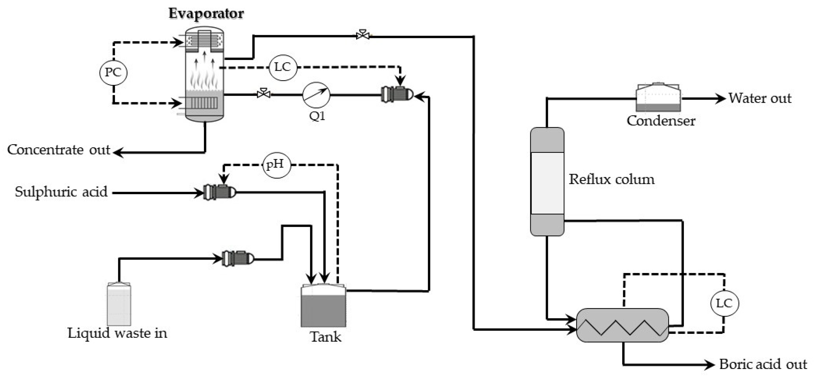
In the case of the nuclear industry, the evaporation method is widely used to the recovery of boric acid (used as a soluble neutron poison to bring under control nuclear fission) from wastewaters generated by pressurized water reactors (PWR or VVER). Using the evaporation procedure results in high decontamination of the waste solution, thus decreasing the possibility of the release of radioactivity into the environment. In addition, thus, for example, in the 1990s, in the Belgian Nuclear Research Center (SCK·CEN), such a process has been worked out [
37]. It is based on the volatility of boric acid in steam. The liquid waste is treated in a semicontinuous evaporator, and the stream loaded with boric acid is fed to a column for fractional condensation with partial reflux. As a result, one obtains a highly concentrated waste containing the radioactive and chemical impurities, together with a small amount of boron, as well as concentrated boric acid solution which may be reutilized and a highly decontaminated solvent, free of the boron.
Figure 9 shows a schematic presentation of this installation.
More detailed, evaporation of the low-level liquid waste (LLLW) is done in a stainless-steel steam evaporator at about 180 °C and pressure of around 8 bars. During the first phase, evaporation of LLLW loaded to the system results in formation a boric acid loaded steam of increasing concentration, as the distillate is used as feed for the evaporator, instead of LLLW. After that, the incoming waste stream could be evaporated without further accumulation of boric acid in the vessel. The boric acid can be recovered in the next unit of the installation.
The main advantages of both the distillation and evaporation methods are the simplicity, high efficiency of the solute removal, standing above others in ratio of the quantity and quality per unit of time, and relatively low operating costs.
The main drawbacks of these methods, in turn, are high construction cost, energy, and maintenance; large size of installation; elevated temperatures; corrosion problems; and scaling or foaming.
4. Thermal Methods of the Radioactive Waste Immobilization
If radioactive waste is stored in liquid form, it may enter the environment by leaching with numerous aqueous streams. In a solid form, risk of the radioactive matter by leaching is many times smaller. Waste solidifying may be reached primarily by its chemical incorporating into the structure of an appropriate matrix, e.g., of cement or glass, and is mainly used for high-level waste (HLW). Physical stabilization of waste is mainly realized by using materials that do not form chemical bonds with the radionuclides, e.g., bitumen or cement. It is used for intermediate level radioactive waste (ILW), as well as for HLW.
Selection the proper form (matrix) for immobilizing radioactive waste is a problem far-reaching beyond its durability. Priority is given to use reliable, simple, cheap, and easy operating methods; only in certain cases should costly or complex ones be used. The choice of immobilization technology should also consider the physical and chemical nature of the waste, as well as type of storage and disposal facility to which the waste will be sent [
38].
Below, we present three immobilization methods that are realized in the elevated temperatures.
4.1. Incorporation into Bitumen (Bituminization)
The technological process of bituminization the radioactive waste permits forming solid blocks containing both liquid or solid radioactive waste and being a good choice for safe, long-term storage and disposal [
39]. The process is preferably used for medium-activate waste, mainly chemical sludges, concentrates from evaporators, solutions arising from an ion-exchange purified liquid waste, organic solvents, and used natural and synthetic sorbents, ash, and plastics. The first industrial-scale plant started operation in 1965 in Belgium. Since then, bituminization has been introduced in many countries, such as the UK, Czechoslovakia, France, Germany, Poland, Russian Federation, and the USA, among others.
Bitumen is a thermoplastic organic, solid, or semi-solid material in low and medium temperatures and is formed by mixtures of different high molecular weight hydrocarbons that are soluble in carbon disulphide. They contain also small quantities of sulfur, nitrogen, and oxygen compounds and traces of other elements, such as metals. The lowest temperature at which volatile bitumen components begin to burn with an open flame under normal conditions (flash point) cannot be reached during waste treatment for safety reasons. Bitumen used as matrix material has the relatively high flashpoint, usually in the range of 250 to 300 °C.
High stability of bitumen with respect to alpha, beta, or gamma radiation is an important feature determining:
- ✓
the maximum loading amount of radioactive waste into the bitumen filled containers and
- ✓
behavior of the final form of waste under storage and disposal conditions.
There are two basic types of the bituminization process: batch or continuous method. The first one is preferably used for processing portioned waste to prepare a certain number of packages of conditioned waste. Continuous bitumen processing, in turn, is used to form solid waste streams in the process facilities working repeatedly. In both cases, the resulting conditioned solid product is ready for long lasting, safe storage and, further, for disposal.
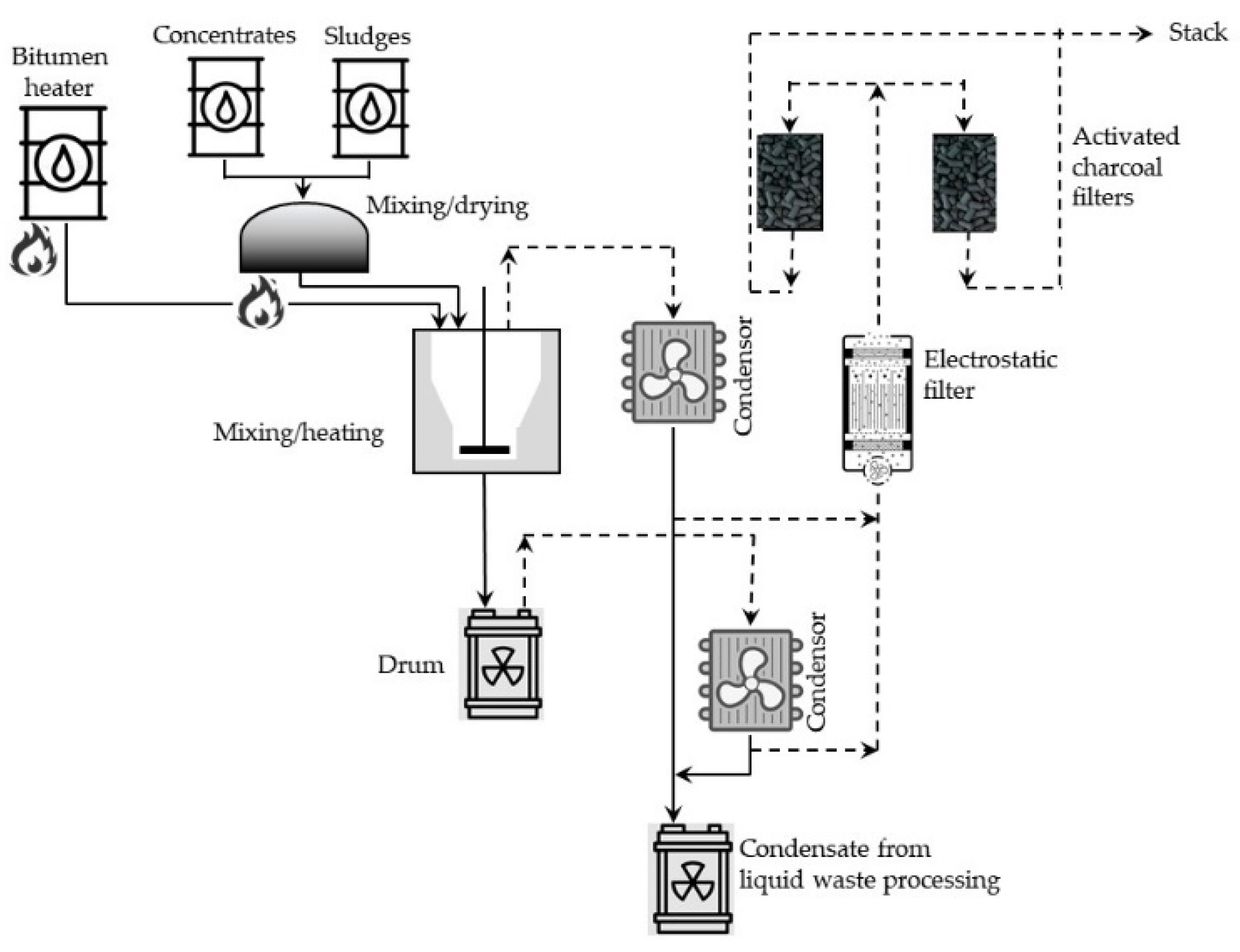
Batch processes, in general, consist of two stages: (1) drying either liquid or solid radioactive waste portions and (2) mixing the dried material with heated (usually to 200–230 °C), molten bitumen. The mass of these mixed portions of solid residue depends on the type and mass of the bitumen. Walls of the mixing vessel, in many cases, are additionally heated to about 300 °C. In such conditions, most of the water evaporates, and particles of the solid residue are suspended in the bitumen. The resulting mixture is stirred further in the elevated temperature to evaporate the excess of water and then poured into metal barrels (hobocks) and cooled for solidifying contents of the drums. A simplified diagram of the batch bituminization installation operating in the reprocessing plant at the Research Center for the Applications of Nuclear Energy (SCK CEN, Mol, Belgium) is shown in
Figure 10.
At present, batch process is not commonly used because bituminization installations operating in the continuous mode seem to be less complicated and cheaper. In this method, the waste stream is continuously delivered at a constant rate to hot bitumen and mixed to form a uniform product. Then, final matter is poured into steel containers in a constant flow rate. Two versions of the continuous processes are the extrusion method and thin film evaporation.
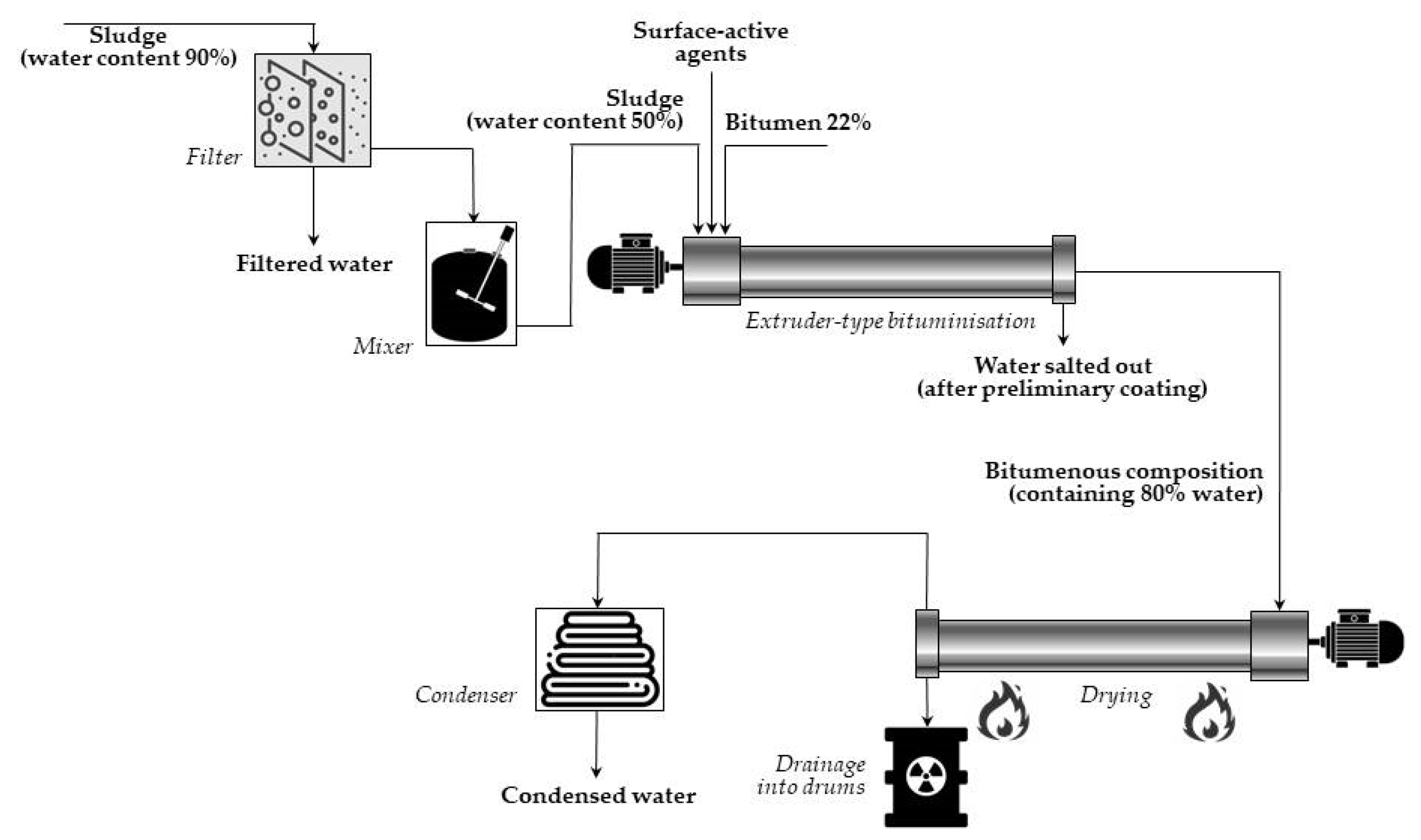
In the case of
extrusion systems, concentrates are introduced continuously into a screw extruder, simultaneously with bitumen, heated at 130–200 °C. When passing through the extruder, the waste is thoroughly mixed with bitumen, and water is simultaneously evaporated. The somewhat low temperature (130–140 °C) of the bitumen-waste mixture has been found to be high enough to keep the viscosity at the appropriate value for the extrusion process. The final product is a homogenous suspension of mineral particles of waste coated with a layer of bitumen mixed with a bitumenic solution of the soluble components of waste. Then, the final mixture is poured into hobocks and left to cool and solidify. A simplified diagram of (continuous) extruder-type bituminization is presented in
Figure 11.
Since 1965, when the first extruding installation started operation at the Commissariat a l’Energie Atomique (CEA, Marcoule, France), a large number such facilities have been created world-wide for processing different concentrates from liquid radioactive waste.
In the thin film evaporating process, liquid waste and/or organic ion exchangers are first concentrated to obtain material containing about 60% of dry matter. Next, preheated waste sludge and bitumen are put separately at the top of the thin-film rotary evaporator, mixed, and both streams move along the heated compartment. There, residual water present in the mixture is gradually evaporated, and the mineral residues from the waste are mixed with bitumen. Finally, the bituminous mix of waste is poured at the bottom into the steel containers, and the generated vapor is condensed in a set of condensers. One of the first thin-film evaporators (Luwa L 150) for bitumen coating of radioactive concentrates was constructed in the CEA Production of Plutonium Center in Marcoule (France) in 1969 [
40].
The only bituminization installation in Poland operates in the Radioactive Waste Management Plant (RWMP) located in Otwock-Swierk. The waste pre-treatment is performed in the evaporation facility, in the reverse osmosis installation, or in a tank for sorption purifying aqueous wastes using synthetic inorganic sorbents. After such pre-treatment, solid concentrates are bituminized: radioactive sludge is mixed with bitumen at a temperature of 220–250 °C. As a result, about 99% of the water contained in the sludge is evaporated before the product is poured into the metal storage drums. An important problem in the ongoing process is the need to keep a high temperature of the mixture (up to 250 °C) inside the tank and even higher temperature (up to 300 °C) at its walls. Such conditions may result in thermal decomposition of the bitumen and the waste, spontaneous combustion, or explosion of the content of the drum [
41]. The installation for the bituminization operates with the non-emulsified bitumen of the P-60 or D-35 type [
42].
Ultimately, the profits of using bitumen are [
43]:
- ✓
the device is simple,
- ✓
the used material is relatively inexpensive,
- ✓
temperature of the process is relatively low,
- ✓
bitumen can form a homogeneous mixture with waste of different composition, and
- ✓
volume of the final product is even 5 times smaller than in the cementation.
The main disadvantage is that the bitumen is easily combustible, and there is a possibility that it may come into an exothermic interaction with some components of waste at high temperature. Decreasing content in the waste of the compounds that may oxidize bitumen at processing temperature (e.g., metal nitrates) may protect the bitumen mixture from the dangerous ignition of stored waste.
4.2. Vitrification the Radioactive Waste
Vitrification (in the UK, or
glassification, in the United States) is the conversion of a material into a glassy form to stabilize radioactive waste before storing it. Currently, the process is the most important waste solidification process. Vitrification has been studied since the 1950s, when the nuclear industry was started. Initially, natural soils were used as a material for forming glass [
44]. However, the necessity of heating to high temperatures (~1500 °C), required for glass melting and producing homogeneous, as well as bubble-free end-product, has resulted in searching for alternative glasses. At present, borosilicate glass of lower melting point, and which accept up to 40% by weight of waste, was proposed as the best solution. In the Soviet Union, however, phosphate glass was applied for vitrification waste. Later, in Russia, use of borosilicate glass vitrification technology has been also applied. The search for suitable glasses is still ongoing. The studies are also conducted in Poland: at the AGH University of Science and Technology (Cracow) [
45] and at the Institute of Chemistry and Nuclear Technology (Warsaw) [
46].
At present, vitrification is carried out by heating to high temperature and rapid cooling in both in-situ and ex-situ modes (for the contaminated soil or for high level liquid waste (HLLW) from the nuclear fuel reprocessing, respectively).
Removal of radioactively contaminated soils could induce radiation exposure to workers from dust and fugitive gas emissions, resulting in an increase in the risk to the environment. A good solution to prevent this seems to be the in-situ vitrification (ISV), which uses an electric power for heating the soil to an extremely high temperature (in the range of 1600–2000 °C) necessary for heating and melting it. For this purpose, two electrodes are placed in a contaminated ground, and an electric current is delivered. Melting begins in the surface zone of the earth and moves downwards. As the soil melts, the electrodes descend into the solid part, causing melting of the sequent layers of soil. When the power is turned off, the molten soil cools down and turns into a glass-like block with the electrodes remaining in it. Any radioactive matter is trapped in this glass bloc and may stand underground for a long time, leaching protected. The method is highly effective for near-surface contamination, and modern methods of vitrification allow for treatment up to depths of about 10 m.
Ex-situ vitrification (ESV) resembles ISV; however, it is carried out in specially designed chambers outside the place of contamination or the storing place of waste. Heating elements of the melter are either plasma torches or electric arc furnaces. When the plasma torch technology is used, waste and the silica flux are fed into a rotating hearth and placed on the chambers’ walls by centrifugal force. On rotation, the waste passes through the plasma flux generated by the immobile plasma burner. To remove molten material from the furnace, the rotation is slowed down, and the slag is poured through the valve in the bottom. Effluent gases, in turn, enter a separate vessel where they are oxidated by combustion. The arc furnace, in turn, is equipped with carbon electrodes and cooled sidewalls, able to work by a continuous feeding system and a system for treatment of an off gas. In this version of the process, the waste is loaded into a chamber and heated to a temperature sufficient to melt the glass. After excretion, the vitrificated waste is cooled down to form a storage-suitable product.
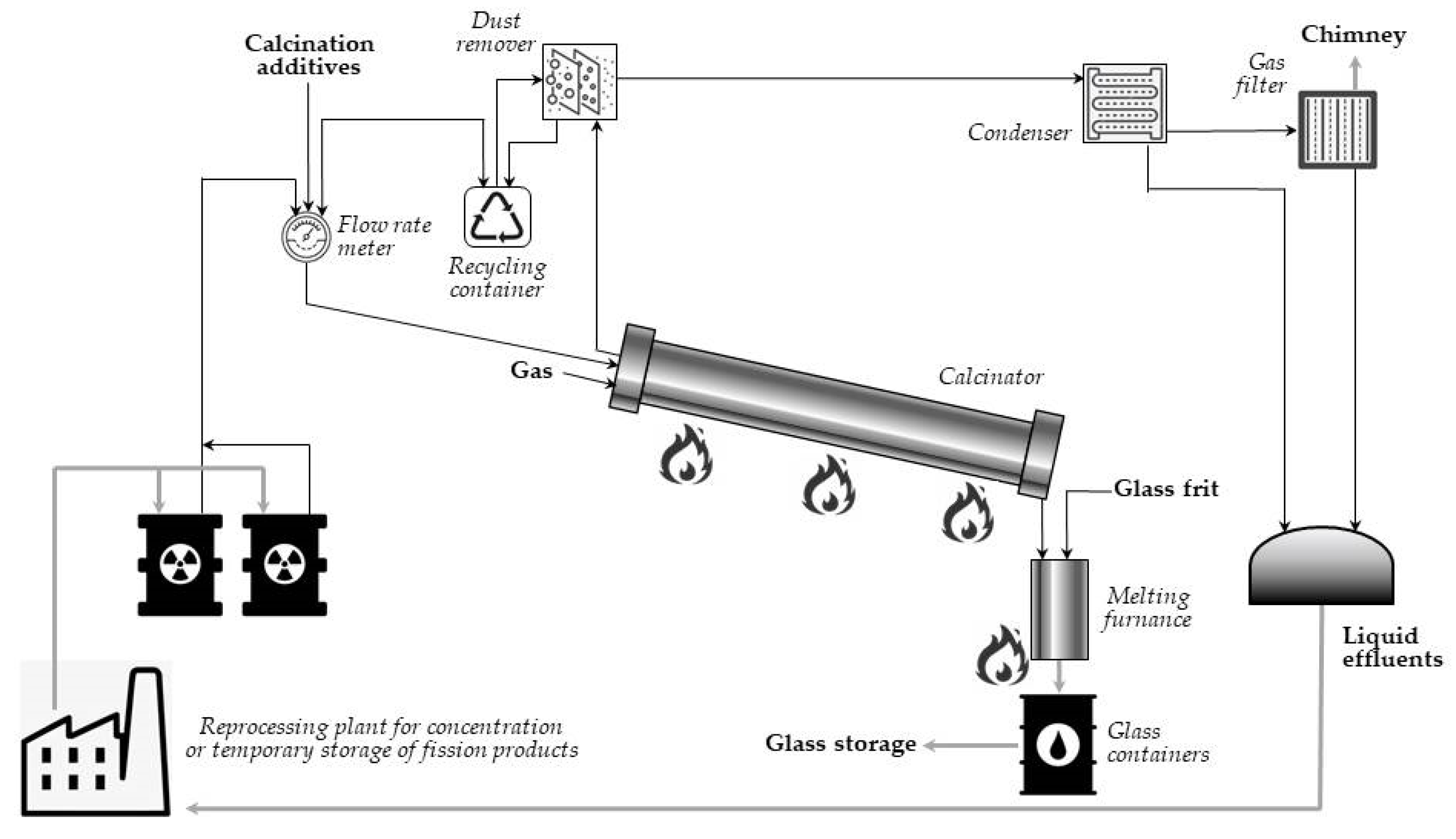
In its full pattern, vitrification of radioactive waste is a multi-stage process: first, the waste is mixed with a substance that crystallizes upon heating (e.g., sugar, sand), and the mixture is calcined to remove water and increase stability of the glassy product. Then, the calcined materials enter the heated furnace as a continuous stream and are mixed with crushed glass to bond the radioactive waste with glass. Finally, the molten product is poured into an encapsulation container, cooled down, and solidified in a final glass suitable for storage. Such a vitrification process allows the dangerous radioactive waste to be immobilized for thousands of years. A simplified flowsheet of the vitrification plant at Marcoule (AVM) is presented in
Figure 12 [
21,
47]. In the process, temperature of heating the melter is about 1050 °C.
The AVM process has been successfully used in France for 30 years, and, in Marcoule and La Hague, three vitrification installations were built based on this process. A similar plant was also built in Sellafield in the UK [
48].
It has been estimated that vitrification of HLLW waste sludge into durable glass reduces volume by 77% when loading waste is about 28% (expressed as dry oxide mass). Vitrification of LLMW sludges and incinerator waste, in turn, reduces volume to 97% when loading waste is about 50–75%. This large reduction of the waste volume minimizes both long-term storage costs and the environmental danger [
49].
The main advantages and shortcoming of the vitrification process are presented in
Table 2.
Despite numerous limitations, vitrification is the most desirable method in places where large amounts of radioactive waste of similar composition are available, e.g., the HLW, resulting from operation of the nuclear power plants or the nuclear medicine laboratories.
4.3. Immobilization Radioactive Waste in the Synthetic Rock (Synroc)
In the 1970s, at Pennsylvania State University (USA), it was suggested that glass is relatively less thermodynamically stable than crystalline materials and that the use of synthetic minerals would be beneficial [
52,
53]. Minerals may have been stable for millions of years under conditions characteristic of a deep geological storage site [
52,
54]. So, at Australian National University (ANU), in 1978, a material was formulated, named Synroc, an abbreviation for synthetic rock. The name describes ceramic materials composed similarly to the titanate minerals. They were chosen because of their high chemical stability and pronounced ability to immobilize in the crystalline structure elements usually present in HLW. Minerals, proposed for Synroc, had been found in the environment and, over millennia under extremely difficult conditions, have demonstrated their ability to retain naturally occurring radioactive elements, such as uranium or thorium, among others. Different from borosilicate glass matrix, an amorphous solid solution without any crystalline form, Synroc ceramics incorporate radioactive waste in its crystalline structure.
Till now, a large number of the potential Synroc materials have demonstrated their high resistance against water leaching and, thus, demonstrated their potency in HLW immobilization. For example, V.M. Oversby, from Lawrence Livermore National Laboratory (USA), has proposed that waste from the Chernobyl Unit 4 reactor may be stored in a ceramic material that contains the mineral zirconolite (CaZrTi
2O
7; radionuclides in lattice: Zr, Rare Earths minor actinides [
55]) with some addition of perovskite (CaTiO
3; (Sr, RE, An) [
56]), nepheline ((Na, K)AlSiO
4; (Na, K, and Ca) [
57]), and spinel (MgAl
2O
4; corrosion products [
58]). It has been reported that waste loadings up to 50% of uranium can be achieved if pyrochlore (mineral, such as the zirconolite) is used [
55].
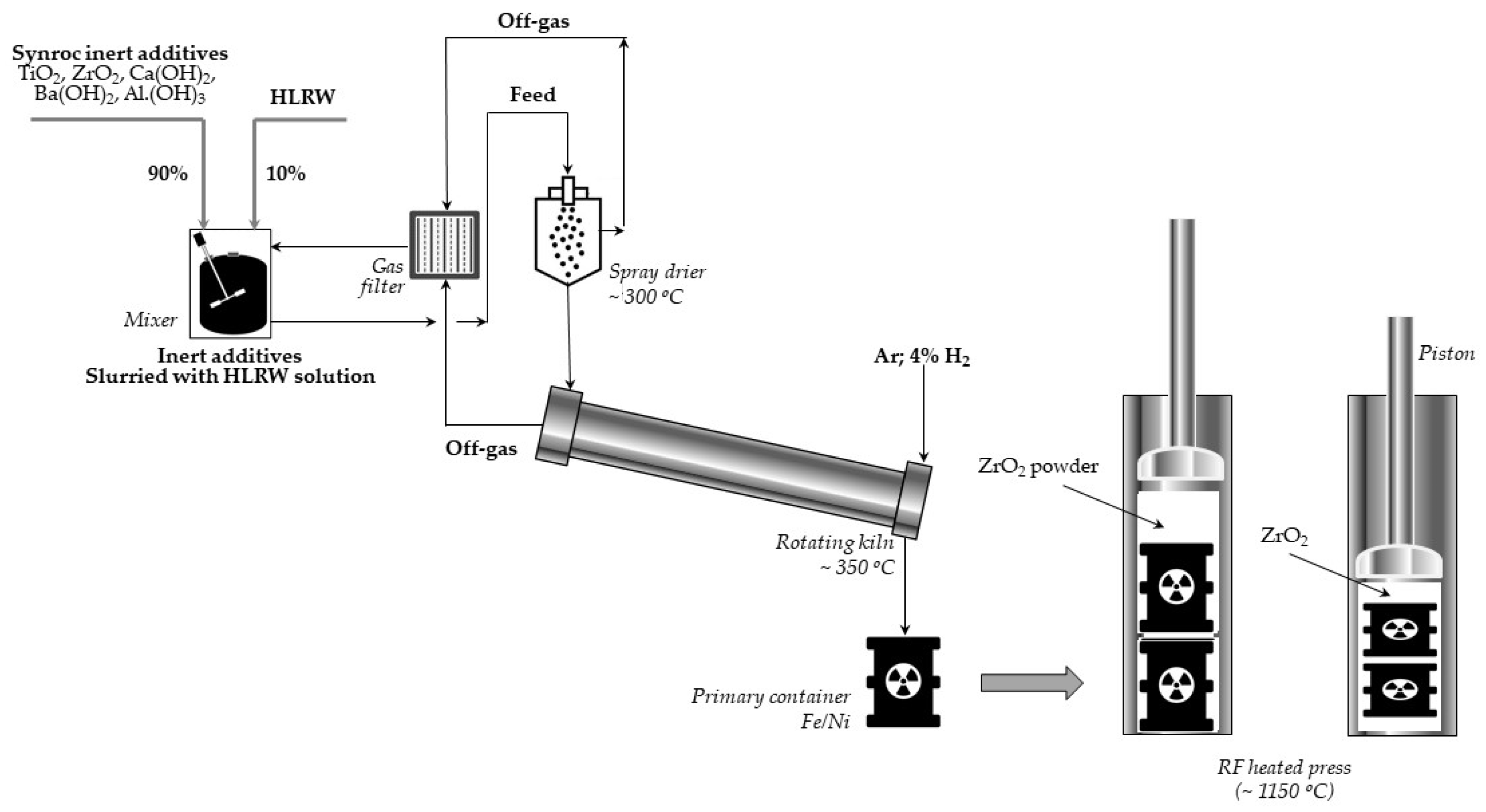
Let us briefly present the thermochemical procedure for immobilization of radioactive waste proposed by the ANU and performed in Sandia [
59]. In the first stage of three titanate minerals: hollandite, zirconolite, perovskite, and sometimes also rutile (titanium oxides), are combined into a slurry to which a certain quantity of HLLW is supplemented. This mixture is dried and calcined at 750 °C to obtain powder. Then, the material is inserted into a bellows-like stainless steel container and pressed at 1150–1200 °C. Finally, the resulting Synroc cylinder is loaded into the canister suitable for a long-term disposal. The scheme of the process using the Sandia method is presented in
Figure 13.
The problem with the Synroc method of disposal the radioactive waste, similarly to the vitrificated waste, arises during its long-term storage in deep underground storage facilities. Although the waste cannot be leached by different water streams, it remains strongly radioactive for a long time and can have a negative impact on the environment.
The leaching rate for Synroc depends on the element concerned. The highest values occur for Cs and Ba (1–2 × 10
−7 g/cm
2d; at 95 °C), while the lowest occurs for U (5 × 10
−10 g/cm
2d in the same conditions). It has been found also that the leaching rate significantly increases for nearly all the elements, while temperature of the process increases. Comparison of leaching rate for Synroc with data established for the borosilicate glass shows that, in the case of uranium, the process is 3000 times slower for Synroc than for glass [
60].
The main advantages and shortcoming of the radioactive waste in the Synroc are presented in
Table 3.
5. Radioactive Waste in Poland
5.1. Radioactive Waste Received by the Radioactive Waste Management Plant (ZUOP) in Poland
Low and intermediate radioactive waste received by the Radioactive Waste Management Plant in Poland (ZUOP) results from the use of radioactive isotopes in nuclear medicine, industry, and scientific research, during the production of open and sealed radioactive sources at the National Center for Nuclear Research (NCBJ) and during the operation of the MARIA research reactor, which is used, inter alia, to produce radioisotopes.
These wastes occur in both liquid and solid forms.
- ✓
The main source of low-level liquid waste is the MARIA reactor. Intermediate liquid waste is generated during the production of radioactive sources and, in some cases, during decontamination of contaminated surfaces.
- ✓
The source of solid waste is also the MARIA reactor and the radioactive isotope production plant (National Center for Nuclear Research, Radioisotope Center POLATOM). Radioactive waste of reactor origin is, e.g., filters (from cooling and ventilation systems), decontamination wastes, and spent elements of reactor apparatus and equipment.
Wastes from isotope production include:
- ✓
unused radioactive materials from isotope production,
- ✓
waste decontamination solutions, and
- ✓
used contaminated apparatus and laboratory equipment.
In addition, solid waste also comes from hospitals, clinics and other institutions using isotope techniques located throughout the country. Waste generated during the use of radioactive substances for medical purposes, particularly for cancer diagnosis and therapy, consists of ampoules after radioactive preparations, as well as syringes, lignin, film, protective clothing, worn equipment, and decontamination waste. An exceptional group of medical waste is radium sources (Ra-226). The collection of these wastes from users requires adequate preparation (security) during the transport and then storage. This is of particular importance in a situation where the sources have been unsealed.
Used closed radioactive sources, including isotopic smoke detectors, are mainly collected from institutions outside the NCBJ area. Their suppliers are usually companies that install new alarm devices, which also dismantle old alarm systems, pick up the recalled detectors, and store them until they are handed over to the ZUOP.
5.2. Thermal Methods of Processing the Radioactive Waste in the Radioactive Waste Management Plant (ZUOP)
The collection, transport, processing, and storage of waste generated by users of radioactive materials in Poland is handled by the Radioactive Waste Management Plant (ZUOP). ZUOP is the sole plant in Poland with a permission to manage, dispose of, and store radioactive waste. It is responsible for handling the waste from the moment of collecting it from the producer. ZUOP is also the operator of the National Radioactive Waste Repository (KSOP) in Różan, a surface disposal facility for short-lived, low-, and intermediate-level radioactive waste. KSOP is also used for temporary storing of long-lived waste, mainly alpha-radioactive materials awaiting disposal in a deep geological repository.
The Radioactive Waste Management Plant operates on a commercial basis, and only a little development work is carried in there. The system for the management of radioactive waste and spent fuel in the ZUOP includes minimization of volume and activity, segregation, qualification, processing and conditioning, packaging, and, finally, export to the KSOP.
The main technologies currently used in the ZUOP for the disposal of radioactive waste are:
for solid waste:
- ✓
fragmentation and
- ✓
compression;
for liquid waste:
- ✓
evaporation,
- ✓
reverse osmosis, and
- ✓
solidification technology for sludges and concentrates.
Of the methods of preparing waste for landfilling, currently, only liquid waste is subjected to a process containing a thermal stage. Liquid radioactive waste of low-activity is disposed of using sorption on a mixture of boron carbonate and copper ferrocyanide. This method allows more than 99% of the radioactive material contained in wastewater to be bound. The used and, thus, contaminated sorption material is then solidified with bitumen.
Small volumes (approximately 2 m3/year) of intermediate-activity radioactive waste is concentrated by evaporation. The resulting concentrate, which is not more than 1/30 of the initial volume of wastewater, is solidified with cement or bitumen.
The Radioactive Waste Management Plant also plans to introduce a thermal method of waste treatment in its activities. In cooperation with the external research institutes, it prepares design and construction of an incineration plant for low- and medium-radioactive solid and liquid organic waste.
The currently existing infrastructure of the ZUOP seems to be sufficient for the volume of waste generated in Polish centers using radioactive substances. In the future, along with the development of nuclear energy in the country, expansion and supplementation with new components will be required. Certainly, new methods of processing and conditioning waste of various origins will be introduced. Today, there is already a need to develop a technology for the processing of organic waste, both solid and liquid. For this purpose, the thermal treatment methods seem to be the most justified. In the future, it will also be required to develop a concept for the management of spent fuel from Polish nuclear reactors. Different approaches are considered with a predominance of the ultimate disposal in geological formations.
6. Conclusions
The term “thermochemical processing of waste” means the usage of heat to promote chemical transformations of waste into chemical products different from starting materials and, if possible, into energy. The three main types of thermo-chemical processes used for normal waste management are pyrolysis, gasification, and combustion. All these processes, in different versions, result in the significant reduction of waste mass. In the case of the radioactive waste, this makes them easier to store and less harmful to the environment.
A particular problem with the management of radioactive waste is obtaining a waste form that minimizes the possibility of radionuclide being leached into the environment. It is possible due to such thermochemical processes as bituminization, vitrification, and the Synroc forming method.
To ensure that proper disposal method is chosen, it is necessary balance between the security and the economic aspects.
All the methods are discussed in this work, and examples of the processes used are presented.


 ,
, 


