Abstract
Isolation of spent nuclear fuel assemblies in deep vertical boreholes is analyzed. The main safety features of the borehole concept are related to the repository’s great depth, implying (a) long migration distances and correspondingly long travel times, allowing radionuclides to decay, (b) separation of the repository from the dynamic hydrological cycle near the land surface, (c) stable geological and hydrogeological conditions, and (d) a geochemically reducing environment. An integrated simulation model of the engineered and natural barrier systems has been developed to examine multiple scenarios of the release of radionuclides from the waste canisters, the transport through a fractured porous host rock, and the extraction of potentially contaminated drinking water from an aquifer. These generic simulations include thermal effects from both the natural geothermal gradient and the heat-generating waste, the influence of topography on regional groundwater flow, moderated by salinity stratification at depth, and the role of borehole sealing. The impact of these processes on the transport of select radionuclides is studied, which include long-lived, soluble, sorbing or highly mobile isotopes along with a decay chain of safety-relevant actinide metals. The generic analyses suggest that a deep vertical borehole repository has the potential to be a safe option for the disposal of certain waste streams, with the depth itself and the stable hydrogeological environment encountered in the emplacement zone providing inherent long-term isolation, which allows for reduced reliance on a complex engineered barrier system.
1. Introduction
Disposal of spent nuclear fuel and high-level radioactive waste in deep geological formations is posited a viable option to isolate radionuclides from humans and the environment for sufficiently long time periods. In addition to centralized mined repositories excavated from suitable host rocks, modular waste disposal in vertical or horizontal boreholes drilled into deep sedimentary formations or crystalline basement rocks has been proposed as complementary or alternative solutions to the long-term disposition of radioactive waste. While deep borehole disposal was considered as an option as early as 1957 [1], it has since been evaluated in more detail by multiple countries, including Sweden, the United Kingdom, Germany, and the United States [2,3,4,5,6,7,8,9,10,11,12]. Renewed interest in the technical and economic feasibility of the concept was triggered mainly by the considerable advances in drilling technology by the oil, gas, and geothermal industries, and the potentially long and uncertain lead times and high facility costs of a mined repository. Moreover, it was proposed that the modular and scalable deep borehole disposal concept provides a cost-effective alternative to mined repositories, specifically for countries with small waste inventories [13,14] or to accommodate waste forms generated by next-generation advanced reactors [15].
The basic concept of waste disposal in deep vertical boreholes consists of a relatively simple design, in which waste canisters are emplaced in the lower part of a borehole drilled into crystalline basement rock, the upper part of the borehole being sealed to isolate the disposal section from the accessible environment (see, for example, the reference design described in [16]). As a variant of such a vertical borehole repository, directional drilling technology can be used to gradually deviate from the vertical direction of the access hole at a kick-off point above the target depth and to create a horizontal disposal section within a suitable formation, which may be a sedimentary or crystalline host rock. The deep horizontal borehole concept has been described in [17], with generic safety calculations for a repository in shale discussed in [18,19,20].
While all three repository systems—mined repositories as well as deep vertical and horizontal borehole repositories—share the ultimate goal of safely containing and isolating radioactive waste for a sufficiently long time until the radionuclides have decayed away to a level that no longer poses environmental health risks, there are some notable differences between the three options. These differences are related to all aspects of repository design and operation, including pre- and post-closure safety as well as socio-economic considerations [15,21]. Some of these similarities and differences are described in [10,11,15,17,22,23,24] and will be further discussed below.
A modeling-based analysis is a key element of the so-called safety case, which presents arguments and supporting evidence for a repository system’s performance and the evaluation of its safety [25,26]. The specific scope and level of detail of the analysis reflects the development stage of the proposed concept, the amount of information available at the time of the analysis, and the magnitude of the potential hazard as estimated in previous assessments [27]. Deep borehole repositories are at a relatively early stage within this process, specifically because no disposal sites have been identified and because research and development by national waste organizations focus on mined repositories. Nevertheless, a series of preliminary safety analyses for borehole repositories have addressed a subset of features, events, and processes (FEPs) for generic sites and reference repository designs [6,7,9,11,18,19,20,28,29]. While these studies discuss many aspects (including operational safety during the pre-closure phase [30] and economics [11,31]), the post-closure analyses focus on thermal effects, borehole sealing issues, as well as driving forces and stabilizing effects, such as density stratification. Both argillaceous and crystalline formations have been looked at in these safety analyses. In these models, individual FEPs may be treated separately to evaluate the impact of a specific process on the performance of a particular subsystem, or they may be coupled and integrated into a total system performance assessment model that typically calculates the exposure dose for a reference case and a suite of disruptive event scenarios.
Recent studies of vertical deep boreholes [6,9,16] focused on reference designs with a disposal zone at depths considered to be within the envelope of drilling capabilities (i.e., 3–5 km with a diameter of 0.34 m) in relatively closely packed square arrays (e.g., 400 m spacing). A holistic optimization of the deep borehole concept [11] suggests that shallower depths (combined with lower loading densities) have the potential to offer a more optimal combination of drilling, emplacement, and site characterization costs, while still meeting long-term performance objectives. The current study examines the disposal of canisters containing individual spent nuclear fuel assemblies from a pressurized water reactor in a 3 km deep vertical borehole drilled into crystalline basement rock at a generic disposal site.
It is evident from the previous assessments cited above that the long-term safety of a deep borehole repository mainly depends on the magnitude of natural and repository-induced driving forces, the physical and chemical retention properties of the geosphere, and the role of the borehole itself as a potential pathway for fast fluid flow and preferential radionuclide transport. The main goal of the analysis is to understand the interactions among key processes across a range of spatial and temporal scales as the radionuclides are released from the canisters, and from where they migrate along the borehole and within the fractured host rock towards the biosphere.
The paper is organized as follows. Section 2 provides an overview of the modeling methodology. The specific features and processes represented in the model and the details of the model itself are discussed in Section 3. Results of a reference scenario are presented in Section 4, along with sensitivity analyses of select assumptions and properties. The final section discusses the conclusions derived from the analysis and offers some general views on the viability of the deep borehole disposal concept.
2. Methodology
The performance of a vertical borehole repository is assessed by means of a high-fidelity numerical model. An integrated modeling approach has been developed to calculate the exposure dose, accounting for coupled thermal-hydrological processes and the transport of radionuclides through the engineered and natural barrier systems. We considered it essential to use a physics-based simulator within an integrated modeling framework because the relative importance of individual FEPs and the strength of interactions and feedback mechanisms can only be evaluated if examined concurrently and in a fully coupled mode, i.e., without making overly simplified assumptions about the exchange of information across subsystem interfaces.
The software used for the analysis is the iTOUGH2 simulation-optimization framework [32], which includes an extended version of the TOUGH2 non-isothermal flow and transport code [33]. The module EOS1nT [34] is used, which calculates coupled fluid and heat flow of water and an arbitrary number of radionuclides in trace concentrations through fractured porous media. Fluid flow is described by Darcy’s law. Heat is transported by convection and conduction. All thermodynamic fluid properties are calculated as a function of pressure, temperature, and salinity. Radionuclides are transported by advection and diffusion, potentially retarded by adsorption to the solid phase. Daughter products from radioactive decay are tracked. The governing continuum equations are discretized using the integral finite difference method in space and a fully implicit scheme in time. The resulting coupled, nonlinear algebraic equations are solved simultaneously by means of Newton–Raphson iterations. Preconditioned conjugate gradient solvers invert the set of linear residual equations arising at each iteration (see [33,35,36] for a description of the numerical scheme employed in the TOUGH2 code).
A dual-permeability modeling approach [37,38,39] captures the interactions between an interconnected fracture-network continuum and the low-permeability rock matrix of the crystalline bedrock. The fracture and matrix continua overlap in space, with global flow occurring in both media, and fluid, heat, and radionuclides being exchanged locally with the rock matrix across an interface area that depends on average fracture spacing and other geometrical parameters. For formations with sufficiently high fracture density (so that the fracture network can be approximated as a continuum), this approach is numerically very efficient despite the fact that each spatial point is represented by two grid elements. The dual-permeability approach is considered suitable for simulating large-scale flow and transport through fractured-porous media, and was used for the safety assessment at the proposed repository site at Yucca Mountain [40].
The source-term and biosphere models are implemented in a simplified way. The chemical processes of casing and canister corrosion and waste-form degradation are not explicitly simulated. Instead, the effects of corrosion are implemented by increasing the canister’s permeability and diffusivity at a pre-defined time, which depends on the scenario being evaluated. At that specified time, a fraction of the radionuclide inventory is mobilized instantaneously, whereas the remainder is released slowly according to a fractional waste degradation rate model. Similarly, the processes in the biosphere are not explicitly modeled, but simply represented by a conversion factor that translates the radionuclide concentration flux of the produced drinking water into an annual exposure dose. The chosen pumping rate and conversion factor are consistent with one of the reference biosphere models proposed by the International Atomic Energy Agency (IAEA) [41]. Additional details about the overall modeling methodology can be found in [42].
3. Model Development
3.1. Repository Layout
The layout of a vertical borehole repository can be adjusted in a flexible manner, depending on the overall disposal strategy, the amount and type of waste, and the geological conditions at a potential site. The latter determines the minimum depth and available length of the borehole’s disposal section. Small waste inventories may be disposed of in a single borehole. For example, the approximately 2000 capsules containing 137CsCl and 90SrF2 from the chemical processing of defense waste [43] would fit into a single, approximately 1500 m long, 8.5-inch (21.5 cm) diameter borehole if the capsules were placed end-to-end [18] or, if three-packs are stacked into a suitable container, in a less than 550 m long borehole of diameter 12.25 inch (31.1 cm) [44]. Canisters holding individual assemblies from a pressurized water reactor would fit into a slightly larger, 13.3-inch borehole [11]. In such an arrangement, nuclear fuel spent in 30 years by a 1 GWe reactor could be disposed of in seven boreholes, each having a 1500 m long emplacement section. Larger-diameter boreholes up to 800 mm (31.5 inches) have also been proposed, which could receive canisters holding multiple assemblies or vitrified waste forms [4,45]. Borehole diameters may be adjusted to accommodate consolidated fuel rods or other waste forms (e.g., granular calcine waste) [10,14,16,45,46].
The modular approach afforded by the borehole concept provides considerable flexibility [11,47] and an opportunity to optimize waste disposal for specific inventories, waste forms, and host rocks. The number of boreholes needed to dispose of accumulated and future radioactive waste at a specific repository site primarily depends on whether one centralized, a few regional, or many local repositories will be built. Compared to having numerous facilities, larger centralized facilities may benefit from having the potentially large (and uncertain) fixed cost components of site characterization [11], licensing, and security being spread over a larger disposal inventory. Furthermore, a centralized approach could reduce costs due to efficiencies created from using large-scale industrial processes at a centralized operation (for drilling [48], waste handling, emplacement, etc.), and control of the inventory. However, constructing multiple, smaller repositories could lead to faster implementation at or near the site where the waste is being generated [15]. This reduces risks and costs related to long-distance transportation. Due to the relatively low sensitivity of performance with respect to the details of host-rock properties and the ability to tolerate conservative assumptions [19,20,42], site requirements, specifically regarding properties and the extent of a formation suitable to host a borehole repository, would be easier to meet [15]. Moreover, while the probability of being affected by certain disruptive events (e.g., seismicity) may increase, the consequences of such events would be compartmentalized and thus diminished [19,42].
These performance attributes associated with deep borehole disposal would also reduce requirements on site investigations compared to the detailed fracture characterization that is typically required for some mined repositories [49]. Due to both the smaller inventory emplaced in each borehole and reduced thermal load, the operational phase of a local borehole repository is shorter than that of a large, mined repository, in which the access shafts may remain open for as long as 100 years to allow for emplacement and ventilation [50]. As with any technology developed, experiences and lessons learned from the construction and operation of a local borehole repository could be used or adapted to the conditions at another site, leading to more efficient regulatory approvals and accelerated technology adoption.
Finally, public opposition to a repository stems not only from perceptions of risk, but also from the inherent inequity of concentrating radioactive wastes at a very limited number of repository sites [21,51,52]. Thus, more numerous local disposal projects may be more likely to obtain consent by stakeholders and public acceptance because the assumed risks and likely benefits associated with nuclear energy production are more transparent to the community and achieve greater equity.
Once the number of boreholes at a given site is determined, there is still considerable flexibility in the layout of the repository system. The design (length of disposal section, borehole spacing, total depth, etc.) can be adjusted and optimized depending on geological conditions, site characteristics, drilling costs, access, and other restrictions (e.g., minimum borehole spacing requirements due to thermal load [11]). Boreholes may be drilled along a line at a given interval, on a lattice, or other suitable patterns. This flexibility can be further increased by making use of directional drilling technology, which enables drilling multiple wells from a single well pad, using slanted or horizontal boreholes, with the possibility to create long disposal sections, potentially in multiple directions or vertically stacked [17,46].
Vertical boreholes drilled on a regular surface pattern can be more efficiently analyzed at a conceptual state by taking advantage of inherent symmetries, where the effects from neighboring boreholes can be accounted for without the need to simulate all boreholes. Specifically, assuming that the boreholes are drilled parallel to each other at a constant separation distance along a straight line, a simple, three-dimensional (3D) symmetry cell can be defined, bounded by vertical planes going through the borehole axis and the vertical plane half-way between two boreholes. If the repository is situated on the floor of a relatively wide valley, the regional flow field is also approximately symmetric, with the hills or mountains on the side of the valley—the watershed divide and recharge zone—forming one symmetry plane, and the deepest points along the valley floor—typically the zone of groundwater discharge into a river—forming another symmetry plane. Finally, the release of potentially contaminated groundwater into a river or an array of drinking water wells is also approximately symmetric or can be readily accounted for. By making these symmetry planes reflective (i.e., impervious to fluid and heat flow as well as radionuclide transport [53,54]), it is sufficient to simulate one such symmetry cell to appropriately represent an entire, multi-borehole repository system. The symmetry assumption is violated for the first and last borehole in the array, where the absence of a neighboring borehole on one side leads to the dissipation of pressure, heat, and contamination into a much larger half-space; however, disregarding these special conditions for the two outermost boreholes leads to an overestimation of vertical flow rates and radionuclide concentrations and is thus conservative.
Figure 1 is a schematic of a waste disposal system consisting of multiple parallel boreholes drilled at 100 m intervals on a line near the discharge zone of a valley. Each vertical borehole penetrates the 200-m thick near-surface drinking water aquifer before entering crystalline bedrock. The waste emplacement zone extents from a depth of 1.5 km to the borehole’s total depth of 3 km. While generic, this configuration is considered sufficiently realistic and common to be suitable for the purposes of this analysis.
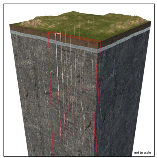
Figure 1.
Schematic of a deep vertical borehole repository (not to scale). The repository consists of multiple, parallel boreholes drilled vertically into crystalline bedrock, each accommodating 200 canisters containing a single fuel assembly from a pressurized water reactor. The waste emplacement section is between a depth of 1.5 and 3 km. The red box indicates the modeled symmetry cell. The borehole diameter is exaggerated.
3.2. Computational Grid
The performance of the vertical borehole repository system is evaluated using a computer model that captures and integrates key safety-relevant features, events, and processes. As discussed above, the model domain consists of a single symmetry cell, which is bounded by reflective symmetry planes on its lateral sides, and appropriately specified conditions at the land surface and the bottom boundary, which is at a depth of 3.5 km.
To numerically solve the governing equations, the model domain is spatially discretized into volume elements, for which mass and energy balance equations are formulated. The computational grid must be designed such that it properly represents the relevant features over multiple scales, from the centimeter thick casing to the multi-kilometer dimensions of the geosphere. Moreover, steep gradients in pressure, temperature, and radionuclide concentrations, which occur mainly within the borehole and the near field of the repository, must be resolved with sufficient accuracy to avoid numerical artifacts. This is accomplished by generating an unstructured grid with multiple levels of nested refinement. In particular, the far field is discretized using a 3D Cartesian grid with continually increasing grid spacing at greater distances from the vertical borehole. However, to avoid excessive refinement of the near field, a two-dimensional (2D) axial-radial subgrid is developed of the borehole and its immediate vicinity, taking advantage of the fact that both the geometry of all engineered barrier components (waste form, canister, casing, borehole wall, seals, backfill, and drilling disturbed zone) are cylindrical, and that the driving forces and thus flow and transport processes within the borehole occur in axial and radial directions only. This axial-radial near-field subgrid is embedded into the Cartesian grid of the far field, resulting in an accurate and computationally efficient multiscale model of the entire repository system. Details about the gridding approach can be found in [42].
Figure 2 shows the computational grid, with insets revealing its nested structure. The visualization of the 2D axial-radial subgrid of the borehole and repository near field (up to a radial distance of 10 m) shows the discretization of two waste canisters within the cased borehole. The 4.5 m long spent nuclear fuel assemblies are contained in 5.5 m long canisters (including end caps with appropriate fittings for potential retrieval). Canisters are on average spaced 2 m apart, a distance sufficient to allow for the installation of a buffer or bridge plug. With this configuration, 200 canisters are to be emplaced in the 1.5 km long disposal section.
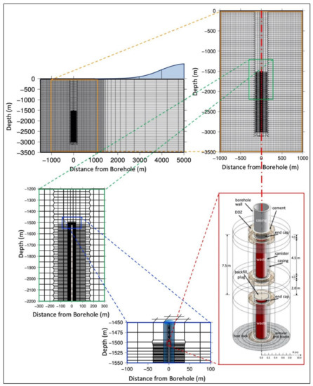
Figure 2.
Cross sections through unstructured computational grid, showing nested mesh refinement; a two-dimensional, radial-axial subgrid representing the borehole, engineered barrier system, and near field is integrated into the three-dimensional Cartesian mesh of the far field.
The computational grid shown in Figure 2 consists of 82,284 volume elements and 194,661 connections between them. Up to eight unknown primary variables are solved for each element. A mesh with higher resolution (148,344 elements and 354,827 connections) was also generated, yielding only insignificant differences in the calculated results. The original mesh was therefore considered sufficiently accurate.
Next, we discuss various components of the model, starting with the waste, followed by other elements encountered along the pathway of the radionuclides to the biosphere.
3.3. Radionuclide Inventory and Waste Mobilization
The long-term safety of a repository is ultimately assessed by its ability to isolate the waste from the accessible environment. While the waste to be disposed of consists of a large number of radioisotopes, only a small fraction thereof becomes a potential threat to human health and the environment once placed in a deep borehole repository. For example, those with very short half-lives or very small inventories are unlikely to lead to groundwater contamination, because they have decayed to exceedingly small concentrations even before or shortly after waste emplacement. Other radionuclides are either insoluble in groundwater, or their migration through the geosphere is greatly retarded (by adsorption, complexation, and matrix diffusion) such that considerable time passes before they conceivably reach near-surface ecosystems. The stability of the waste form, the containment within the canister and other components of the engineered barrier system, and the properties and conditions of the host rock (mainly its great depth, long-term isolation and stability, low permeability and porosity, and geochemically reducing conditions) further lower the risk of waste mobilization and prolong the transport time to the accessible environment. It is this isolation in both space and time that effectively and significantly reduces the danger radionuclides pose to future generations if released from canisters in a deep borehole repository compared to an accidental release of radionuclides today at the land surface. Therefore, the list of radionuclides that need to be considered for a post-closure, long-term safety assessment is different from the list of radionuclides relevant to ensure safe operation, handling, transportation, emplacement, and other pre-closure activities.
A comprehensive list of radionuclides that are present in spent fuel from a pressurized water reactor will be evaluated for a site-specific safety analysis. However, for this generic study, we consider a representative subsect of activation and fission products as well as those from an actinide alpha decay chain. The fission products 129I, 79Se and 99Tc have been identified in most comprehensive safety assessments [28,55,56,57,58] as some of the main contributors to the effective dose people at the land surface may be exposed to. They have either a high initial inventory, a high specific activity or dose coefficient, are highly soluble or mobile, or exhibit a combination of these factors. 36Cl is an example of a potentially safety-relevant activation product. Finally, to examine the impact of ingrowth as radionuclides migrate through the geosphere, we consider the alpha decay chain 245Cm → 241Am → 237Np → 233U → 229Th, which is also referred to as the 4n+1 or neptunium series.
Table 1 summarizes the inventory and key radiological parameters of these isotopes. The dose coefficients indicate the potential radiological impact arising from consuming 1.2 m3 yr−1 of water that is exclusively derived from the contaminated aquifer above the repository [41]; no other exposure pathways are considered in the current model.

Table 1.
Initial inventory, specific activity, dose coefficient and instant release fraction of selected radionuclides.
The radionuclide inventory is encapsulated in the solid uranium dioxide pellets of the assemblies, which are individually contained in canisters. After the canister is breached, the solid waste form starts to disintegrate as a result of a complex radiologic oxidation process that is approximated by a radionuclide-specific instant release fraction of a portion of the inventory [59,60] and an annual fractional degradation rate of the waste form [61]. The concentrations of radionuclides in the brine surrounding the canisters depends on the release rate, the solubility limit [11,62], and the transport processes between the waste form and the borehole, which leads to a diffusion-limited or solubility-limited source-term model. Some disruptive events may lead to an early release of radionuclides. Once dissolved in the pore-water, radionuclides become mobile and can be transported by diffusion or advection along the borehole [11,20,29], into the near field, and through the geosphere to the biosphere.
The waste also releases decay heat, which is supplied as a time-dependent source function to each canister. This function, taken from [63], comprises the heat generated from all radionuclides present in the canister.
3.4. Engineered Barrier System
In a borehole repository, the main components of the engineered barrier system are the waste form, the canister, and plugs used to seal the borehole. Unlike in a mined repository, where the bentonite buffer is an important engineered barrier component [65,66,67], the space between the canister and the casing in a borehole repository is limited. Backfill material may be used to mechanically stabilize the canisters, to distribute the stacking load, and to increase the thermal conductivity [7,11,68]. However, in our safety assessment, no hydrological or geochemical barrier function is assigned to this material, nor to the cement in the annulus between the casing and the host rock. The primary purpose of the casing is to facilitate emplacement (and potential retrieval) of the canisters. The casing is expected to corrode shortly (less than 100 years) after repository closure; therefore, no post-closure safety requirements are formulated for the casing.
As discussed in Section 3.3, the waste is conceptualized as a heat-generating, degrading, radionuclide-releasing amorphous porous matrix contained within the canister. The corrosion and eventual perforation of the canisters and casing are approximated by a time-dependent increase in permeability [19], with the assumption that the canister is breached after 10,000 years. The role of borehole seals has been examined for a large, centralized, vertical borehole repository in [7,11,69,70], and for a smaller, modular, horizontal borehole repository in [20]. While backfilling and plugging the borehole is an integral part of repository closure activities, it is difficult to assess or predict the long-term performance of such seals. We therefore make conservative assumptions about the permeability of the backfilled borehole to examine whether it acts as a preferential flowpath for contaminated water driven by thermal effects or other driving forces.
3.5. Natural Barrier System
As highlighted in the introduction, the great depth where waste will be emplaced is the main safety-relevant aspect of a borehole repository. Modern drilling technology makes it possible to access deep formations and subsurface structures that are far removed from the biosphere and have been isolated from near-surface hydrological processes beyond the time frames for which the safety of the repository must be assessed. While demonstrating past stability of the host rock is necessary but not sufficient to predict future repository performance, it is an indication that the waste will be strongly protected and isolated by the natural barrier system, complemented by the components of the engineered barrier system, which are mainly needed to mitigate repository-induced effects during the relatively short thermal period.
Directional drilling and geosteering offer an opportunity to construct horizontal waste disposal sections that are both deep and long, capable of exploiting the typically layered stratigraphy of sedimentary host formations [17,19]. Clearly, sufficient disposal depths can also be reached with vertical boreholes. Due to the borehole’s orientation, the waste emplacement section is likely located within crystalline bedrock. We therefore choose to examine fractured basement rock as the potential host formation for a deep vertical borehole repository.
The type and properties of basement rocks vary greatly; any safety calculation must therefore be based on parameters derived from site characterization data. For our generic analysis, we aim at representing common features of basement rocks with associated parameter values rather than a specific structure. Crystalline rocks can be characterized as fractured porous media, whose site-scale hydraulic behavior is dictated by the connectivity and hydraulic properties of the fracture network. Fracture density, aperture, and connectivity are related to the stress regime and are thus depth-dependent [71]. For transport of radionuclides through fractured bedrock, the rock mass between the fractures is also important, as it retards contaminant migration by matrix diffusion [72].
We base the characteristics of our generic fractured host rock on the global dataset of hydrogeological properties evaluated by [73]. Accounting for scale effects, measurement artifacts, lithology, geological province, seismotectonic activity, and other geological factors, they derived a depth-dependent permeability model and determined the permeability variance. While the predictive power of this correlation is limited, it is considered appropriate as a site-scale, generic representation of fractured crystalline basement rock. Its fractured-porous nature is modeled using a dual-permeability continuum approach, where the matrix permeability and porosity are constant at 10−20 m2 and 1%, respectively, and the fracture permeability is heterogeneous, with the depth-dependent mean value taken from the regression given by [73], and the spatial variability generated geostatistically using sequential Gaussian simulation and a spherical semi-variogram [74] with a log-variance of 1.0 and correlation lengths in horizontal and vertical directions of 100 m and 1 km, respectively. Anisotropy is introduced because spatial variability is expected to be strongly related to brittle fault zones, which tend to be steeply inclined at the depths of interest to this study. The exchange of fluids and radionuclides between the fracture and the matrix continua is controlled by the geometry of the fracture network, which is assumed to consist of two sets of planar, parallel, infinite fractures with arbitrary angle between them and a fracture spacing of 100 m. Global matrix-matrix flow is allowed only in the vertical direction. Figure 3 depicts the permeability field that is mapped onto the numerical grid shown in Figure 2.
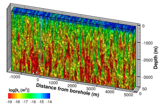
Figure 3.
Three-dimensional distribution of depth-dependent, random, spatially correlated permeabilities of fracture continuum below a 200 m thick aquifer. Y-axis and borehole diameter exaggerated by a factor of 100.
The crystalline bedrock is assumed to be overlaid by permeable quaternary sediments that form a regional aquifer. Groundwater is pumped from this aquifer. The concentration of radionuclides in the produced drinking water determines the exposure dose, which is examined as the main measure of repository performance.
3.6. Processes and Parameters
To the extent feasible, the safety analysis is performed using a high-fidelity, multiscale simulator, with key processes fully coupled and most subcomponents of the repository system integrated in a single computational model [20,42]. However, the current model only accounts for coupled thermal-hydrological processes, with the effects of geochemical and geomechanical processes indirectly included through the use of effective and time-dependent parameters. Moreover, the source term and biosphere are represented in a simplified manner (see Section 2 and Section 3.3). Table 2 summarizes material-specific hydrological, thermal, and transport parameters.
Table 2.
Material-specific hydrological, thermal, and transport parameters.
Table 3 lists radionuclide-specific transport properties. The molecular diffusion coefficient in bulk water for the radionuclides of interest can be calculated using the Stokes–Einstein law [75] or determined experimentally [76,77,78,79]. During the simulation, an effective diffusion coefficient is dynamically calculated to account for temperature effects and the impacts of salinity on viscosity according to the Stokes–Einstein equation [75]. The effective diffusion coefficient in a porous medium is further related to porosity by a factor of [80].
Table 3.
Radionuclide-specific transport parameters.
The Kd value describes instantaneous, reversible, linear sorption of radionuclides onto the solid matrix of the host rock. Sorption coefficients are sensitive to the oxidation state of the radionuclide, which in turn is related to groundwater composition, specifically ionic strength and pH. Coefficients for granitic host rocks are taken from [81] for oxidation states that yield lower Kd values.
Mobilization of radionuclides may be suppressed if they are poorly soluble. Whether the release of a radionuclide is solubility-limited is checked by comparing its concentration in the pore water, taking the maximum solubility limit measured for groundwaters in granitic bedrock, as summarized in [11].
3.7. Initial and Boundary Conditions
The initial distribution of pressures, temperatures, and salinity are obtained by a near-steady simulation under the following boundary conditions. As described in Section 3.2, the four vertical model boundaries are symmetry planes; they are therefore impervious to fluids, radionuclides, and heat. The bottom boundary is a no-flow boundary for fluids and radionuclides. However, the temperature at a depth of −3500 m is kept constant at 120 °C, which is derived from assuming a mean annual surface temperature of 15 °C and a geothermal gradient of 30 °C km−1. This configuration allows for conductive heat flow across the base of the model.
The boundary conditions at the land surface are set such that a regional flow regime develops with the potential for upward flow of groundwater. In general, topography of the land surface generates a water-table relief, which in turn leads to recharge-discharge patterns that impact groundwater flow up to a certain depth [53]. To induce topography-driven regional groundwater flow, it is assumed that the repository is located near the floor of a 13 km wide valley, schematically shown in Figure 1 and Figure 2. The two mountain ridges defining the valley are 600 m high and have a Gaussian shape (perpendicular to the valley) with a standard deviation of 1 km. Given that the water table is close to the terrain in most non-arid climate regions, the mountains are recharge zones with a relative overpressure of approximately 60 bars with respect to the valley floor.
While most of the infiltrating water flows within and remerges from relatively shallow, local groundwater systems, regional-scale recharge-discharge patterns may develop with dimensions on the order of the large-scale topographic features. The vertical extent of these topography-induced flow systems not only depends on the relief; flow lines also refract if hydrogeological properties change with depth, either abruptly or gradually.
Moreover, higher fluid density and viscosity, associated with an increase in salinity, may reduce the depth to which such large-scale recharge-discharge patterns penetrate. The role of density stratification for the hydraulic isolation of deep groundwater and thus reduction of advective radionuclide transport has been discussed in [9,44,83]. To account for these effects, it is assumed that the brine below a depth of 1 km has a salinity of approximately 200,000 ppm (corresponding to a NaCl concentration of about 3.8 mol L−1). Because of elevated temperatures, the resulting brine density is lower than that used for the density-stratification analysis performed by [44,83]; note that a lower density contrast weakens density stratification effects.
By letting this system equilibrate for ten million years, the resulting state throughout the modeling domain reflects the regional flow field, with density profiles accounting for the combined effects of pressure, temperature, and salinity.
Figure 4 shows the fluid density distribution and streamtraces of the regional flow field, both affected by freshwater recharge from the mountain ridge. Recall that the mountain ridge is not explicitly included in the model, but its effect is represented by the Gaussian pressure distribution specified along the top of the model domain. The velocity field and streamtraces reveal the impact of the permeability contrast between the aquifer and the bedrock. Moreover, the dense brine not only limits the depth to which freshwater penetrates the bedrock, it also leads to a large, stable region with very small advective flow velocities. Flow rates in the aquifer are significantly higher than those in the freshwater portion of crystalline basement rock, which in turn are much higher than those within the high-density brine region. Velocities vary on the intermediate scale because of the heterogeneity in fracture network permeability.
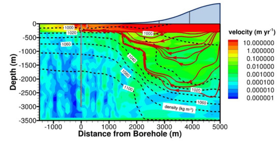
Figure 4.
Initial conditions: Pore water velocity (color contours), fluid density (dashed contour lines), and streamtraces of regional flow field (dark red solid lines). The dark red streamtraces only visualize the direction of the flow field, without reflecting the magnitude of water flux. No streamtraces are shown in the region of essentially stagnant brine. Flow within the mountain ridge (blue-grey area) is not simulated explicitly. The borehole diameter is exaggerated by a factor of 100.
The state shown in Figure 4 are the initial conditions for the simulations described in the following subsections. It is assumed that construction of the vertical boreholes, emplacement of waste, and closure of the repository occur instantaneously and do not lead to significant perturbations of the host rock, except for the creation of a drilling disturbed zone around the borehole. The post-closure evolution of the repository system is then simulated for ten million years.
4. Simulation Results
4.1. Reference Scenario
The reference scenario described above forms the basis for simulating the transport of the radionuclides listed in Table 1 through the engineered barrier system and the fractured bedrock to a well that draws drinking water from the near-surface aquifer. The goal is to understand the overall performance of the deep vertical borehole repository by estimating exposure dose.
The flow field is affected by coupled thermal-hydrological processes. In addition to the naturally occurring, mild gradients in pressure and temperature, there are repository-induced effects, which are mainly driven by the decay heat generated by the disposed spent fuel. As temperatures rise, the pore fluid expands, increasing pressures and inducing advective fluid flow. Moreover, higher temperatures reduce the fluid’s viscosity and accelerate the diffusion of radionuclides, should they be released very early during the thermal period. For example, increasing the temperature from 100 to 150 °C increases the specific fluid volume by about 4%, reduces the viscosity by about 35%, and increases the effective diffusion coefficient by about 40%. However, because the heat output declines relatively rapidly (see [63]), and the released heat dissipates into the surrounding host formation, the maximum increase in temperature (of approximately 60 °C) is reached just a few years after repository closure. As the heat spreads radially out, the maximum temperature in the borehole declines despite the continuous addition of thermal energy to the system. The temperatures reach the initial, ambient distribution after about 100,000 years, which is also the approximate time for the heat to dissipate conductively to the land surface.
The rock volume available for heat absorption is laterally constrained by the heat released from neighboring disposal holes, which are represented in the model by no-flow symmetry planes. Borehole spacing therefore affects the temperature in the near field and the associated coupled thermal-hydrological processes, as discussed in detail in [11]. At a given depth, the temperature distribution between two parallel boreholes is essentially uniform after about 1000 years, with no significant differences between the temperatures in the fracture and matrix continuum. Additionally, note that while the temperature in the lowest section of the borehole briefly reaches 175 °C, no boiling occurs, because the fluid pressure at that depth (more than 200 bars) is far above the boiling pressure (approximately 10 bars) for this maximum temperature. To further examine the impact of thermal loading on repository performance, a sensitivity analysis was performed and will be discussed in Section 4.2 below.
Figure 5 shows the annual dose curves for the reference scenario. These curves can be interpreted as a measure of overall repository performance. The long-lived and highly mobile 129I is the main safety-relevant isotope, followed by 79Se and 36Cl. None of the other radionuclides considered in these simulations (99Tc and the isotopes of the neptunium series; see Table 1 and Table 3) reaches the accessible environment.
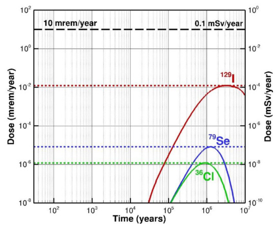
Figure 5.
Annual dose curves for reference scenario. Dose contributions from 99Tc, 245Cm, 241Am, 237Np, 233U, and 229Th are insignificant. The cumulative dose curve from all considered radionuclides is indistinguishable from that of 129I.
The 129I peak dose of 1.2 × 10⁻⁴ mSv yr−1 is three orders of magnitude below a typical dose standard of 0.1 mSv yr−1 (10 mrem yr−1). The peak dose is reached after 3.2 million years. The transport time to the drinking water well is long despite 129I being non-sorbing. Three factors contribute to this outcome: (1) the great depth of the borehole repository and thus long transport distance to the aquifer; (2) absence of a sustained, upwards driving force for advective radionuclide transport through the fracture system, which is a result of density stratification and isolation from surface-induced hydrological perturbations; and (3) retardation due to diffusion of 129I into the stagnant matrix pore water. This combination of mechanisms, which can be considered inherent aspects of the deep borehole repository concept, lead to strong waste isolation and safety even for a long-lived isotope such as 129I.
The peak doses of 79Se and 36Cl are 8.1 × 10⁻⁸ and 1.2 × 10⁻⁸ mSv yr−1, respectively, and are reached after 1.3 and 0.9 million years. Their contributions to the total dose (and the contributions of all the other radionuclides considered in this analysis) are insignificant in comparison to that of 129I. The total exposure dose is therefore given by the dose curve for 129I. The migration times of 79Se and 36Cl are sufficiently long for decay to reduce their activities in groundwater by more than a factor of ten.
The dose curves for 99Tc and all isotopes from the neptunium decay chain are very low mainly because of sorption. The total mineral surface area available for sorption is large enough to immobilize most of the released radionuclides rather than they being dissolved in the more mobile fracture pore water. Much of this mineral surface area is within the rock mass accessed by matrix diffusion; the amount of radionuclides adsorbed within the fracture network and the components of the engineered barrier system is comparatively small. While sorption coefficients vary considerably depending on the geochemical environment, the simulations suggest that even conservatively small values (as assumed here) lead to considerable retardation, indirectly facilitated by the depth of the repository.
Matrix diffusion is a key process, as it not only retards radionuclide transport by dissolution into stagnant pore water, but also because it provides access to sorption sites. Consequently, the effectiveness of matrix diffusion—potentially limited by chemical and physical interactions near the fracture–matrix interface [84]—and its representation in a dual-continuum model needs to be evaluated for site-specific conditions.
Figure 6 shows that despite considerable heterogeneity in the fracture continuum permeability (see Figure 3), plume evolution is diffusion-dominated due to the absence of sizeable driving forces for groundwater movement and associated advective radionuclide transport. Retardation by matrix diffusion further dampens discrete effects from heterogeneity in the fracture continuum. For the given time frames, the diffusion length is considerably larger than the shortest dimension of the matrix blocks (here 50 m to the center of the matrix block); consequently, the differences in 129I activity in the fracture and matrix continua are very small and are thus not visualized. Recall that the effective diffusion coefficient is calculated as a nonlinear function of porosity and temperature.
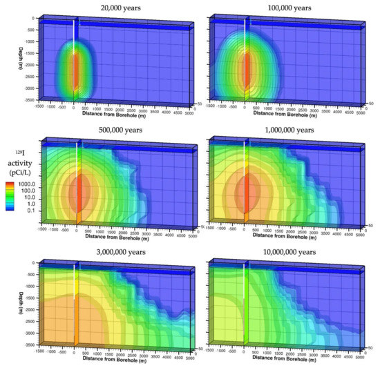
Figure 6.
Simulated distribution of 129I activity in fracture continuum at select times. A vertical slice along the borehole and a horizontal slice along the bottom of the aquifer highlight the radionuclide distributions at these locations of interest. The borehole diameter is exaggerated by a factor of 100.
The advective component of radionuclide migration is only dominant in the aquifer. In the fracture network of the crystalline bedrock, the very slow advective component of 129I transport—driven by the regional, clockwise recharge-discharge pattern—becomes noticeable only after 10 million years.
The spatial extent of elevated activities from the five radionuclides of the 4n+1 series is limited to the repository’s near-field. Multiple factors contribute to this outcome. First, no instant release fraction is associated with these actinides, and their release from the canisters is slow due to the low waste degradation rate. Additionally, note that 245Cm and 241Am decay relatively fast, with 241Am providing an additional source for the long-lived 239Np and ultimately its decay products, specifically 233U. Most importantly, all these radionuclides are effectively immobilized by sorption and matrix diffusion. The geosphere around and above a deep borehole repository thus provides effective isolation of radionuclides released from the canisters. In this reference scenario, the engineered barrier system—with the exception of the waste form itself—does not need to fulfill a crucial barrier function.
4.2. Sensitivity Analyses
Sensitivity analyses were performed to examine the robustness of the reference case results and to clarify some of the explanations made in the previous subsection. In particular, we examine the effects of (1) heat generation, (2) poor borehole sealing in combination with early canister failure, and (3) matrix diffusion and advective transport. Given that 129I is identified as the most safety-relevant, we focus on the annual exposure dose from this radionuclide and its sensitivity to changes in assumptions or parameters.
Figure 7 shows the 129I dose curves for the reference case (red line) along with the results from the sensitivity cases. The reference model considers three principal driving forces that potentially lead to upflow of contaminated water from the repository towards the aquifer: (1) topography-induced regional groundwater flow (see Figure 4), (2) drawdown due to extraction of drinking water from shallow wells, and (3) thermal fluid expansion and associated buoyancy effects triggered by the release of decay heat from the repository.
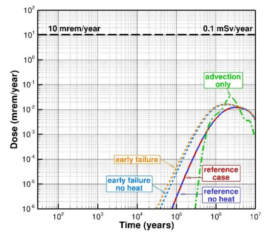
Figure 7.
Sensitivity of 129I dose curve to thermal driving force, backfilling and early canister failure, and diffusion coefficient.
Many previous studies on deep borehole disposal focus on thermal effects as essentially the only driving force available to induce vertical flow. Recall that thermal processes are accounted for in the reference case and are fully coupled with fluid flow and radionuclide transport. Considered processes include conductive and convective heat transport, thermal expansion of the pore space and pore fluids, associated changes in fluid density (leading to buoyancy), temperature-dependence of viscosity, and impact on diffusion coefficients. The energy released by the decaying waste is realistically represented by a time-dependent heat source term.
To examine the impact of repository-induced thermal effects on exposure dose—accounting for all coupled processes and interactions between the engineered barrier system, near field, and fractured geosphere—a sensitivity analysis was performed by removing heat generation from the waste. The simulation is still non-isothermal to account for the natural geothermal temperature gradient and its impact on flow and transport properties. The comparison between the reference case and the case without heat generation (blue line in Figure 7) indicates that the impact of decay heat on peak dose is insignificant for the reference scenario. This is due to the fact that the canister confines the waste for the first 10,000 years, a time frame that is considerably longer than the thermal period. Once radionuclides are released from the canister, they encounter an environment that is very similar to the thermally undisturbed, ambient conditions, making repository-induced thermal effects non-influential on peak dose for the reference scenario. This result is consistent with previous findings [85].
As the driving forces from thermal expansion and buoyancy are aligned with the vertical borehole, it has been argued that sealing of the borehole is essential, especially during the thermal period. To examine this hypothesis, a sensitivity case was run in which the permeabilities of the backfill material within the disposal section and throughout the upper part of the access hole are increased to 10−15 m2 (1 millidarcy) to represent the effects of improperly installed plugs, partial degradation of the backfill material, or separation of the seals from the borehole wall. While such failures may lead to locally higher borehole permeabilities, the chosen value is considered reasonably high if applied over the entire length of the borehole. In addition to increasing borehole permeability, this scenario also assumes that all the canisters and the casing have been breached at the time of repository closure, i.e., the instant release fraction of the radionuclide inventory is mobilized, and waste-form degradation begins immediately.
The results of this combination of ineffective borehole sealing and early canister failure are shown as dotted lines in Figure 7. As expected [11,20,85], immediate radionuclide release due early canister failure and weakened flow resistance along the direct connection between the disposal section and the near-surface aquifer leads to an earlier arrival of 129I at the drinking water well, an effect that is only slightly stronger if heat generation in the repository is accounted for. Moreover, the peak dose is higher (1.6 × 10⁻⁴ mSv yr−1) compared to the reference case (1.2 × 10⁻⁴ mSv yr−1) and peak-dose time is shorter (1.8 vs. 3.2 million years). However, this reduction in repository performance is very minor, which corroborates the robustness of the generic deep borehole disposal concept regarding assumptions about borehole sealing and premature waste mobilization.
The importance of diffusion on radionuclide transport and repository performance is also evaluated. As visualized in Figure 6 for the reference case, the absence of strong driving forces (both natural and repository-induced), combined with relatively low fracture network permeability at the depth of the disposal section, leads to a diffusion-dominated transport regime. While diffusion is the main process that mobilizes radionuclides released from breached canisters and transports them throughout the engineered barrier system and geosphere, it also facilitates retardation by moving radionuclides into the stagnant pore water of the rock matrix. To quantify the role of diffusion on dose, a simulation was performed in which the 129I diffusion coefficient was set to an unphysical value of zero, leaving advection as the only available transport mechanism.
The response to this assumption is complex, as shown by the green line in Figure 7. As expected, the arrival time of radionuclides is delayed due to the slow advective transport velocity. However, the absence of matrix diffusion and diffusive spreading of the 129I plume as it migrates along the borehole and through the fracture network leads to a sharper breakthrough and higher peak dose (of 3.2 × 10⁻⁴ mSv yr−1 after 2.3 million years) with a more intricate shape of the curve caused by heterogeneity in permeability and the three-dimensionality of the flow field. This also demonstrates that the impact of diffusion on exposure dose is multifaceted: very low diffusion coefficients reduce the release from the near field and overall radionuclide transport, whereas overly high diffusion coefficients may overestimate matrix diffusion effects and induce high diffusive mixing, also reducing peak concentrations. It is therefore crucial to determine a realistic effective diffusion coefficient based on both experimental data and appropriate relationships that account for changed conditions and properties.
5. Summary and Concluding Remarks
A generic safety analysis has been performed for the disposal of spent nuclear fuel in a deep vertical borehole repository. Using a repository layout described by a linear array of parallel boreholes, and assuming that drinking water is extracted from a series of wells with a similar pattern, the repository can be represented by a symmetry cell containing one waste-disposal borehole and one extraction well (see Figure 1). A three-dimensional, multi-scale model was developed (see Figure 2), which accounts for coupled fluid and heat flow as well as radionuclide transport through a fractured, heterogeneous crystalline host rock, which is represented by a dual-permeability continuum approach. The model accounts for advective and diffusive transport of water with variable salinity, and transport of potentially sorbing radionuclides, considering parent-daughter decay (see Table 1 and Table 3). After canister breach, radionuclides are released to the near field based on a fractional waste-form degradation model, with a fraction of the inventory released instantaneously. Thermal energy is released according to the decay heat profile of the disposed spent fuel assemblies. Flow and transport from the canisters through the backfilled borehole and the fractured-porous geosphere is simulated in a fully coupled manner. The biosphere is represented by IAEA’s Example Reference Biosphere 1A [41]. Repository performance is mainly discussed in terms of annual exposure dose curves. In addition to a reference scenario (see Table 2), select sensitivity analyses were performed to examine the impact of key assumptions and parameters. The following main observations are made:
- Fluid flow at the depth of a vertical borehole repository is very slow, mainly because (a) permeabilities tend to decrease with depth, (b) hydrological perturbations driven by near-surface processes do not reach the disposal section, and (c) the pressure field is stabilized due to density stratification of the brine.
- Radionuclide migration times from the disposal section to the accessible environment are very long mainly because of (a) long travel distances, (b) the absence of strong driving forces needed to induce advective transport, (c) matrix diffusion, and (d) sorption.
- The peak exposure dose calculated for the generic repository system and related reference scenario is significantly below a stringent dose standard of 0.1 mSv yr−1.
- Thermal effects and the impact of incomplete borehole sealing on overall repository performance are minor, even for an early canister failure scenario.
- It is recommended that both the exposure dose, which is the ultimate metric of repository performance, and intermediate results used to demonstrate the behavior of individual barrier components, be calculated using a comprehensive model of sufficient complexity, capable of accounting for key features and processes as well as the relevant interactions among all elements of the repository system.
While these observations are derived based on a generic disposal concept and a generic site, the analyses suggest that calculated repository performance is relatively insensitive to uncertainties in key assumptions and parameter values, which has direct implications for site characterization needs and the design of the engineered barrier system.
In general, the safety of a radioactive waste repository is tantamount to achieving long-term isolation of decaying radionuclides from the accessible environment. The degree of isolation depends on the waste inventory, overall disposal concept, repository design, and site characteristics. The generic safety analysis presented in this article demonstrates that deep borehole disposal affords isolation that is robust and an inherent aspect of the concept. The depth of the repository is a key safety factor, which is not subject to significant uncertainty. Furthermore, depth reduces the impact of many factors that are difficult to determine, mainly because the deep hydrogeological and geochemical environments are comparatively stable, far removed from dynamic hydrological processes occurring at or near the land surface. Moreover, the repository is less vulnerable to inadvertent or malicious human intrusion. More directly, great depth increases the linear migration distance for radionuclides, and even more effectively increases the geosphere volume available for adsorption and diffusive dilution of radionuclides. Both effects increase travel time, during which the radionuclides decay, drastically reducing concentrations and thus their potential health effects should they arrive at the land surface. It is important to realize that this inherent safety of a borehole repository not only reduces the demands on the accuracy of site characterization, but also on the requirements for the engineered barrier system, which is often complex and whose long-term performance is difficult to assess.
The relative simplicity of a deep borehole repository further increases its physical robustness and that of the assessment of its long-term performance. Advanced drilling technology minimally disturbs the host rock, and no personnel or heavy machinery must be placed underground, neither for repository construction, waste emplacement, nor closure activities. No large openings need to be excavated, drained, and ventilated—all activities that strongly perturb the mechanical, thermal, hydrological, and geochemical conditions in the near field of the repository, and which consequently increase site characterization demands and considerably complicate data analysis. In a borehole repository, waste is emplaced into the fluid-filled borehole, with minimal perturbation of the ambient conditions. Boiling during the thermal period is avoided, further reducing complexity and data needs to understand the associated coupled multi-phase processes and their potential impacts on components of the engineered barrier system.
The generic safety analysis shows that a deep borehole repository is a viable option for the disposal of spent nuclear fuel in crystalline basement rock. This option will be further explored by defining a design basis, by including other potentially relevant FEPs, and by examining additional inventories and waste forms, alternative repository layouts and designs, as well as a range of site-specific geological settings and conditions. Moreover, extensive sensitivity and uncertainty analyses will be performed to improve system understanding and gain confidence in the robustness of the simulation results.
Author Contributions
Conceptualization, S.F., R.A.M., J.G., E.A.B. and J.M.; Formal analysis, S.F.; Investigation, S.F., R.A.M., J.G., E.A.B. and J.M.; Methodology, S.F.; Project administration, R.A.M.; Software, S.F.; Supervision, R.A.M.; Visualization, S.F.; Writing—original draft, S.F.; Writing—review and editing, R.A.M., J.G., E.A.B., and J.M. All authors have read and agreed to the published version of the manuscript.
Funding
This research was supported by Deep Isolation, Inc.
Institutional Review Board Statement
Not applicable.
Informed Consent Statement
Not applicable.
Data Availability Statement
Data used for this generic modeling study are cited in the paper.
Acknowledgments
The authors thank the four anonymous reviewers for their constructive comments and valuable suggestions.
Conflicts of Interest
S.F. is a paid consultant for Deep Isolation, Inc.
References
- National Research Council. The Disposal of Radioactive Waste on Land; National Academy of Sciences: Washington, DC, USA, 1957; p. 153. [Google Scholar]
- O’Brien, M.T.; Cohen, L.H.; Narasimhan, T.N.; Simkin, T.L.; Wollenberg, H.A.; Brace, W.F.; Green, S.; Pratt, H.P. The Very Deep Hole Concept: Evaluation of an Alternative for Nuclear Waste Disposal; Lawrence Berkeley Laboratory: Berkeley, CA, USA, 1979; p. 59. [Google Scholar]
- Woodward-Clyde Consultants. Very Deep Hole Systems Engineering Studies; Office of Nuclear Waste Isolation, Battelle Memorial Institute: Columbus, OH, USA, 1983; p. 352. [Google Scholar]
- Juhlin, C.; Sandstedt, H. Storage of Nuclear Waste in Very Deep Boreholes: Feasibility Study and Assessment of Economic Potential; Svensk Kärnbränslehantering AB (SKB): Stockholm, Sweden, 1989; p. 245. [Google Scholar]
- Nirex. A Review of the Deep Borehole Disposal Concept for Radioactive Waste; United Kingdom Nirex Limited: Harwell, UK, 2004; p. 89. [Google Scholar]
- Brady, P.V.; Arnold, B.W.; Freeze, G.A.; Swift, P.N.; Bauer, S.J.; Kanney, J.L.; Rechard, R.P.; Stein, J.S. Deep Borehole Disposal of High-Level Radioactive Waste; Sandia National Laboratories: Albuquerque, NM, USA, 2009; p. 75. [Google Scholar]
- Arnold, B.W.; Brady, P.; Altman, S.; Vaughn, P.; Nielson, D.; Lee, J.; Gibb, F.; Mariner, P.; Travis, K.; Halsey, W.; et al. Deep Borehole Disposal Research: Demonstration Site Selection Guidelines, Borehole Seals Design, and RD&D Needs; Sandia National Laboratories: Albuquerque, NM, USA, 2013; p. 221. [Google Scholar]
- Arnold, B.W.; Brady, P.; Sutton, M.; Travis, K.; MacKinnon, R.; Gibb, F.; Greenberg, H. Deep Borehole Disposal Research: Geological Data Evaluation; Alternative Waste Forms and Borehole Seals; Sandia National Laboratories: Albuquerque, NM, USA, 2014; p. 116. [Google Scholar]
- Freeze, G.; Stein, E.; Brady, P.V.; Lopez, C.; Sassani, D. Deep Borehole Disposal Safety Case; Sandia National Laboratories: Albuquerque, NM, USA, 2019; p. 94. [Google Scholar]
- Beswick, A.J.; Gibb, F.G.F.; Travis, K.P. Deep borehole disposal of nuclear waste: Engineering challenges. Proc. Inst. Civ. Eng. Energy 2014, 167, 47–66. [Google Scholar] [CrossRef]
- Bates, E.A. Optimization of Deep Boreholes for Disposal of High-Level Nuclear Waste; Massachusetts Institute of Technology: Cambridge, MA, USA, 2015. [Google Scholar]
- Gibb, F.G.F. High-temperature, very deep, geological disposal: A safer alternative for high-level radioactive waste? Waste Manag. 1999, 19, 207–211. [Google Scholar] [CrossRef]
- International Atomic Energy Agency (IAEA). Underground Disposal Concepts for Small Inventories of Intermediate and High Level Radioactive Waste; International Atomic Energy Agency (IAEA): Vienna, Austria, 2020; p. 94. [Google Scholar]
- Chapman, N.A. Who Might Be Interested in a Deep Borehole Disposal Facility for Their Radioactive Waste? Energies 2019, 12, 13. [Google Scholar] [CrossRef]
- Electric Power Research Institute (EPRI). Feasibility of Borehole Co-Location with Advanced Reactors for Onsite Management of Spent Nuclear Fuel; EPRI: Palo Alto, CA, USA, 2020; p. 192. [Google Scholar]
- Arnold, B.W.; Brady, P.V.; Bauer, S.J.; Herrick, C.; Pye, S.; Finger, J. Reference Design and Operations for Deep Borehole Disposal of High-Level Radioactive Waste; Sandia National Laboratories: Albuquerque, NM, USA, 2011; p. 67. [Google Scholar]
- Muller, R.A.; Finsterle, S.; Grimsich, J.; Baltzer, R.; Muller, E.A.; Rector, J.W.; Payer, J.; Apps, J. Disposal of High-Level Nuclear Waste in Deep Horizontal Drillholes. Energies 2019, 12, 28. [Google Scholar] [CrossRef]
- Finsterle, S.; Muller, R.A.; Baltzer, R.; Payer, J.; Rector, J.W. Thermal Evolution near Heat-Generating Nuclear Waste Canisters Disposed in Horizontal Drillholes. Energies 2019, 12, 23. [Google Scholar] [CrossRef]
- Finsterle, S.; Muller, R.A.; Grimsich, J.; Apps, J.; Baltzer, R. Post-Closure Safety Calculations for the Disposal of Spent Nuclear Fuel in a Generic Horizontal Drillhole Repository. Energies 2020, 13, 31. [Google Scholar] [CrossRef]
- Finsterle, S.; Cooper, C.; Muller, R.A.; Grimsich, J.; Apps, J. Sealing of a Deep Horizontal Borehole Repository for Nuclear Waste. Energies 2021, 14, 91. [Google Scholar] [CrossRef]
- Cotton, M. Deep borehole disposal of nuclear waste: Trust, cost and social acceptability. J. Risk Res. 2021, 1–16. [Google Scholar] [CrossRef]
- Svensk Kärnbränslehantering AB (SKB). Choice of Method—Evaluation of Strategies and Systems for Disposal of Spent Nuclear Fuel; Svensk Kärnbränslehantering AB (SKB): Stockholm, Sweden, 2010. [Google Scholar]
- Kochkin, B.; Malkovsky, V.; Yudintsev, S.; Petrov, V.; Ojovan, M. Problems and perspectives of borehole disposal of radioactive waste. Prog. Nucl. Energy 2021, 139, 1–9. [Google Scholar] [CrossRef]
- Bates, E.A.; Driscoll, M.J.; Lester, R.K.; Arnold, B.W. Can deep boreholes solve America’s nuclear waste problem? Energy Policy 2014, 72, 186–189. [Google Scholar] [CrossRef]
- International Atomic Energy Agency (IAEA). Disposal of Radioactive Waste, Specific Safety Requirements, SSR-5; IAEA: Vienna, Austria, 2011; p. 83. [Google Scholar]
- Nuclear Energy Agency (NEA). The Nature and Purpose of the Post-Closure Safety Cases for Geological Repositories; NEA/RWM: Paris, France, 2013; p. 55. [Google Scholar]
- International Atomic Energy Agency (IAEA). IAEA Safety Glossary, Terminology Used in Nuclear Safety and Radiation Protection; IAEA: Vienna, Austria, 2019; p. 278. [Google Scholar]
- Freeze, G.; Voegele, M.; Vaughn, P.; Prouty, J.; Nutt, W.M.; Hardin, E.; Sevougian, S.D. Generic Deep Disposal Safety Case; Sandia National Laboratories: Albuquerque, NM, USA, 2013; p. 372. [Google Scholar]
- Freeze, G.; Stein, E.; Price, L.; MacKinnon, R.; Tillman, J. Deep Borehole Disposal Safety Analysis; Sandia National Laboratories: Albuquerque, NM, USA, 2016; p. 274. [Google Scholar]
- Sandia National Laboratories (SNL). Deep Borehole Field Test Conceptual Design Report; Sandia National Laboratories: Albuquerque, NM, USA, 2016; p. 312. [Google Scholar]
- Bracke, G.; Kudla, W.; Rosenzweig, T. Status of Deep Borehole Disposal of High-Level Radioactive Waste in Germany. Energies 2019, 12, 2580. [Google Scholar] [CrossRef]
- Finsterle, S.; Commer, M.; Edmiston, J.K.; Jung, Y.; Kowalsky, M.B.; Pau, G.S.H.; Wainwright, H.M.; Zhang, Y. iTOUGH2: A multiphysics simulation-optimization framework for analyzing subsurface systems. Comput. Geosci. 2017, 108, 8–20. [Google Scholar] [CrossRef]
- Pruess, K. TOUGH2 User’s Guide, Version 2.1; Lawrence Berkeley National Laboratory: Berkeley, CA, USA, 2012; p. 210. [Google Scholar]
- Finsterle, S. iTOUGH2-EOS1nT: A Nonisothermal Two-Phase Flow Simulator for Water and Multiple Tracers—User’s Guide; Finsterle GeoConsulting: Kensington, CA, USA, 2019; p. 35. [Google Scholar]
- Pruess, K. The TOUGH codes—A family of simulation tools for multiphase flow and transport processes in permeable media. Vadose Zone J. 2004, 3, 738–746. [Google Scholar]
- Finsterle, S.; Sonnenthal, E.L.; Spycher, N. Advances in subsurface modeling using the TOUGH suite of simulators. Comput. Geosci. 2014, 65, 2–12. [Google Scholar] [CrossRef]
- Warren, J.E.; Root, P.J. The Behavior of Naturally Fractured Reservoirs. Soc. Pet. Eng. J. 1963, 3, 245–255. [Google Scholar] [CrossRef]
- Pruess, K.; Narasimhan, T.N. On fluid reserves and the production of superheated steam from fractured, vapor-dominated geothermal reservoirs. J. Geophys. Res. Solid Earth 1982, 87, 9329–9339. [Google Scholar] [CrossRef]
- Pruess, K.; Narasimhan, T. A practical method for modeling fluid and heat flow in fractured porous media. Soc. Pet. Eng. J. 1985, 25, 14–26. [Google Scholar] [CrossRef]
- DOE/OCRWM. Yucca Mountain Repository License Application: Safety Analysis Report; DOE/RW-0573, Update No. 1; U.S. Department of Energy, Office of Civilian Radioactive Waste Management: Las Vegas, NV, USA, 2008; Chapter 2; p. 194. [Google Scholar]
- IAEA. “Reference Biospheres” for Solid Radioactive Waste Disposal; International Atomic Energy Agency: Vienna, Austria, 2003. [Google Scholar]
- Deep Isolation. Spent Nuclear Fuel Disposal in a Deep Horizontal Drillhole Repository Sited in Shale: Numerical Simulations in Support of a Generic Post-Closure Safety Analysis; Deep Isolation, Inc.: Berkeley, CA, USA, 2020; p. 149. [Google Scholar]
- Forsberg, C.W. Rethinking high-level waste disposal: Separate disposal of high-heat radionuclides (Sr-90 and Cs-137). Nucl. Technol. 2000, 131, 252–268. [Google Scholar] [CrossRef]
- Freeze, G.A.; Stein, E.; Brady, P.V.; Lopez, C.; Sassani, D.; Travis, K.; Gibb, F.; Beswick, J. Deep Borehole Disposal Safety Case. Energies 2019, 12, 21. [Google Scholar] [CrossRef]
- Rigali, M.J.; Pye, S.; Hardin, E.L. Large Diameter Deep Borehole (LDDB) Disposal Design Option for Vitrified High-Level Waste (HLW) and Granular Waste; Sandia National Laboratories: Albuquerque, NM, USA, 2016; p. 28. [Google Scholar]
- Gibbs, J.S. Feasibility of Lateral Emplacement in Deep Borehole Disposal of High Level Nuclear Waste; Massachussets Institute of Technology: Cambridge, MA, USA, 2010. [Google Scholar]
- Aadnøy, B.S.; Dusseault, M.B. Deep Borehole Placement of Radioactive Wastes—A Feasibility Study; Norwegian Nuclear Decommissioning (NND): Halden, Norway, 2020; p. 226. [Google Scholar]
- Randeberg, E.; Ford, E.; Nygaard, G.; Eriksson, M.; Gressgård, L.; Hansen, K. Potentials for cost reduction for geothermal well construction in view of various drilling technologies and automation opportunities. In Proceedings of the Thirty-Sixth Workshop on Geothermal Reservoir Engineering, Stanford University, Stanford, CA, USA, 30 January–1 February 2012; p. SGP-TR-194. [Google Scholar]
- Baldwin, T.; Chapman, N.; Neall, F. Geological Disposal Options for High-Level Waste and Spent Fuel; Radioactive Waste Management (RWM): Didcot, UK; Nuclear Decommissioning Agency (NDA): Moor Row, UK, 2018; p. 125. [Google Scholar]
- DOE/OCRWM. Yucca Mountain Repository License Application: General Information; U.S. Department of Energy Office of Civilian Radioactive Waste Management: Las Vegas, NV, USA, 2008. [Google Scholar]
- Easterling, D. Fair rules for siting a high-level nuclear waste repository. J. Policy Anal. Manag. 1992, 11, 442–475. [Google Scholar] [CrossRef]
- Kasperson, R.E.; Rubin, B.L. Siting a Radioactive Waste Repository: What Role for Equity. In Equity Issues in Radioactive Waste Management; Kasperson, R.E., Ed.; Oelgeschlager, Gunn and Hain, Publishers, Inc.: Cambridge, MA, USA, 1984; pp. 118–136. [Google Scholar]
- Tóth, J. Gravitational Systems of Groundwater Flow-Theory, Evaluation Utilization; Cambridge University Press: Cambridge, UK, 2009. [Google Scholar]
- Hutton, D.V. Fundamentals of Finite Element Analysis; McGraw-Hill: Boston, MA, USA, 2004; p. 494. [Google Scholar]
- Nagra. Project Opalinus Clay, Safety Report, Demonstration of Disposal Feasibility for Spent Fuel, Vitrified High-Level Waste and Long-Lived Intermediate-Level Waste (Entsorgungsnachweis); National Cooperative for the Disposal of Radioactive Waste (Nagra): Wettingen, Switzerland, 2002; p. 472. [Google Scholar]
- Andra. Dossier 2005 Argile: Synthesis—Evaluation of the Feasibility of a Geological Repository in an Argillaceous Formation—Meuse/Haute-Marne Site; Andra (Agence Nationale pour la Gestion des Déchets Radioactifs): Paris, France, 2005; p. 241. [Google Scholar]
- Nuclear Waste Management Organization (NWMO). Postclosure Safety Assessment of a Used Fuel Repository in Sedimentary Rock; NWMO: Toronto, ON, Canada, 2013; p. 610. [Google Scholar]
- National Cooperative for the Disposal of Radioactive Waste (Nagra). Kristallin-I, Safety Assessment Report; Nagra: Wettingen, Switzerland, 1994; p. 468. [Google Scholar]
- Lemmens, K.; Gonzalez-Robles, E.; Kienzler, B.; Curti, E.; Serrano-Purroy, D.; Sureda, R.; Martinez-Torrents, A.; Roth, O.; Slonszki, E.; Mennecart, T.; et al. Instant release of fission products in leaching experiments with high burn-up nuclear fuels in the framework of the Euratom project FIRST-Nuclides. J. Nucl. Mater. 2017, 484, 307–323. [Google Scholar] [CrossRef]
- Johnson, L.; Ferry, C.; Poinssot, C.; Lovera, P. Spent fuel radionuclide source-term model for assessing spent fuel performance in geological disposal. Part I: Assessment of the instant release fraction. J. Nucl. Mater. 2005, 346, 56–65. [Google Scholar] [CrossRef]
- Svensk Kärnbränslehantering AB (SKB). Long-Term Safety of KBS-3 Repositories at Forsmark and Laxemar—A First Evaluation; Svensk Kärnbränslehantering AB (SKB): Stockholm, Sweden, 2006; p. 613. [Google Scholar]
- Duro, L.; Grivé, M.; Cera, E.; Gaona, X.; Domènech, C.; Bruno, J. Determination and assessment of the concentration limits to be used in SR-Can; Svensk Kärnbränslehantering AB (SKB): Stockholm, Sweden, 2006; p. 135. [Google Scholar]
- Ansolabehere, S.; Deutch, J.; Driscoll, M.; Holdren, J.P.; Joskow, P.L.; Lester, R.K.; Moniz, E.J.; Todreas, N.E. The Future of Nuclear Power: An Interdisciplinary MIT Study; Massachusetts Institute of Technology: Cambridge, MA, USA, 2003; p. 180. [Google Scholar]
- Carter, J.T.; Luptak, A.J.; Gastelum, J.; Stockman, C.; Miller, A. Fuel Cycle Potential Waste Inventory for Disposition; U.S. Department of Energy, Office of Used Fuel Disposition: Washington, DC, USA, 2012; p. 328. [Google Scholar]
- Sievänen, U.; Karvonen, T.H.; Dixon, D.; Hansen, J.; Jalonen, T. Design, Production and Initial State of the Underground Disposal Facility Closure; Posiva Oy: Eurajoki, Finland, 2012; p. 112. [Google Scholar]
- Keto, P.; Dixon, D.; Jonsson, E.; Gunnarsson, D.; Börgesson, L.; Hansen, J. Assessment of Backfill Design for KBS-3V Repository; Svensk Kärnbränslehantering AB (SKB): Stockholm, Sweden, 2009; p. 119. [Google Scholar]
- Sellin, P.; Leupin, O.X. The use of clay as an engineered barrier in radioactive-waste management—A review. Clays Clay Miner. 2013, 61, 477–498. [Google Scholar] [CrossRef]
- Gibb, F.G.F.; McTaggart, N.A.; Travis, K.P.; Burley, D.; Hesketh, K.W. High-density support matrices: Key to the deep borehole disposal of spent nuclear fuel. J. Nucl. Mater. 2008, 374, 370–377. [Google Scholar] [CrossRef][Green Version]
- Gibb, F.G.F.; Travis, K.P. Sealing Deep Borehole Disposals of Radioactive Waste by ‘Rock Welding’. In Proceedings of the 15th International High-Level Radioactive Waste Management Conference, Charleston, SC, USA, 12–16 April 2015; pp. 401–406. [Google Scholar]
- Bates, E.A.; Salazar, A.; Driscoll, M.J.; Baglietto, E.; Buongiorno, J. Plug design for deep borehole disposal of high-level nuclear waste. Nucl. Technol. 2014, 188, 280–291. [Google Scholar] [CrossRef]
- Rutqvist, J.; Stephansson, O. The role of hydromechanical coupling in fractured rock engineering. Hydrogeol. J. 2003, 11, 7–40. [Google Scholar] [CrossRef]
- Zhang, Y.Q.; Liu, H.H.; Zhou, Q.L.; Finsterle, S. Effects of diffusive property heterogeneity on effective matrix diffusion coefficient for fractured rock. Water Resour. Res. 2006, 42, 8. [Google Scholar] [CrossRef]
- Achtziger-Zupancic, P.; Loew, S.; Mariethoz, G. A new global database to improve predictions of permeability distribution in crystalline rocks at site scale. J. Geophys. Res. Solid Earth 2017, 122, 3513–3539. [Google Scholar] [CrossRef]
- Deutsch, C.V.; Journel, A.G. GSLIB, Geostatistical Software Library and User’s Guide; Oxford University Press: New York, NY, USA, 1998; p. 369. [Google Scholar]
- Einstein, A. Über die von der molekularkinetischen Theorie der Wärme geforderte Bewegung von in ruhenden Flüssigkeiten suspendierten Teilchen. Annalen Der Physic 1905, 17, 549–560. [Google Scholar] [CrossRef]
- Latrous, H.; Ammar, M.; M’Halla, J.; David, F.; Fourest, B.; Duplessis, J.; Oliver, J.; Chemla, M. Comparative Study of Self-Diffusion of the Trivalent Ions Eu3+(4f) and Am3+(5f) in Aqueous Solutions. Inorg. Chim. Acta 1984, 94, 158–159. [Google Scholar] [CrossRef]
- Latrous, H.; Oliver, J. Self-diffusion coefficients and structure of the trivalent transplutonium ion curium and gadolinium in aqueous-solutions. J. Radioanal. Nucl. Chem. 1992, 156, 291–296. [Google Scholar] [CrossRef]
- Glaus, M.A.; Rosse, R.; Van Loon, L.R.; Yaroshchuk, A.E. Tracer diffusion in sintered stainless steel filters: Measurements of effective diffusion coefficients and implications for diffusion studies with compacted clays. Clays Clay Miner. 2008, 56, 677–685. [Google Scholar] [CrossRef]
- Sato, H.; Yui, M.; Yoshikawa, H. Ionic diffusion coefficient of Cs+, Pb2+, Sm3+, Ni2+, SeO42− and TcO4− in free water determined from conductivity measurements. J. Nucl. Sci. Technol. 1996, 33, 950–955. [Google Scholar] [CrossRef]
- Millington, R.J.; Quirk, J.P. Permeability of porous solids. Trans Faraday Soc. 1961, 57, 1200–1207. [Google Scholar] [CrossRef]
- Andersson, J. Data and Data Uncertainties—Compilation of Data and Data Uncertainties for Radionuclide Transport Calculations; Svensk Kärnbränslehantering AB (SKB): Stockholm, Sweden, 1999; p. 162. [Google Scholar]
- Clayton, D.; Freeze, G.; Hadgu, T.; Hardin, E.; Lee, J.; Prouty, J.; Rogers, R.; Nutt, W.M.; Birkholzer, J.; Liu, H.H.; et al. Generic System Modeling—Fiscal Year 2011 Progress Report; Sandia National Laboratories: Washington, DC, USA, 2011; p. 466. [Google Scholar]
- Park, Y.J.; Sudicky, E.A.; Sykes, J.F. Effects of shield brine on the safe disposal of waste in deep geologic environments. Adv. Water Resour. 2009, 32, 1352–1358. [Google Scholar] [CrossRef]
- Jakob, A. Matrix Diffusion for Performance Assessment—Experimental Evidence, Modelling Assumptions and Open Issues; Paul Scherrer Institute (PSI): Villigen, Switzerland, 2004; p. 94. [Google Scholar]
- Arnold, B.W.; Vaughn, P.; MacKinnon, R.; Tillman, J.; Nielson, D.; Brady, P.; Halsey, W.; Altman, S. Research, Development, and Demonstration Roadmap for Deep Borehole Disposal; Sandia National Laboratories: Albuquerque, NM, USA, 2012; p. 151. [Google Scholar]


Publisher’s Note: MDPI stays neutral with regard to jurisdictional claims in published maps and institutional affiliations. |
© 2021 by the authors. Licensee MDPI, Basel, Switzerland. This article is an open access article distributed under the terms and conditions of the Creative Commons Attribution (CC BY) license (https://creativecommons.org/licenses/by/4.0/).