

State of the Art Review of Reinforcement Strategies and Technologies for 3D Printing of Concrete


Abstract
:1. Introduction
2. Review of Existing Reinforcement Concepts
2.1. Conventional Concrete Reinforcement
2.1.1. Rebar
2.1.2. FRP Sheet
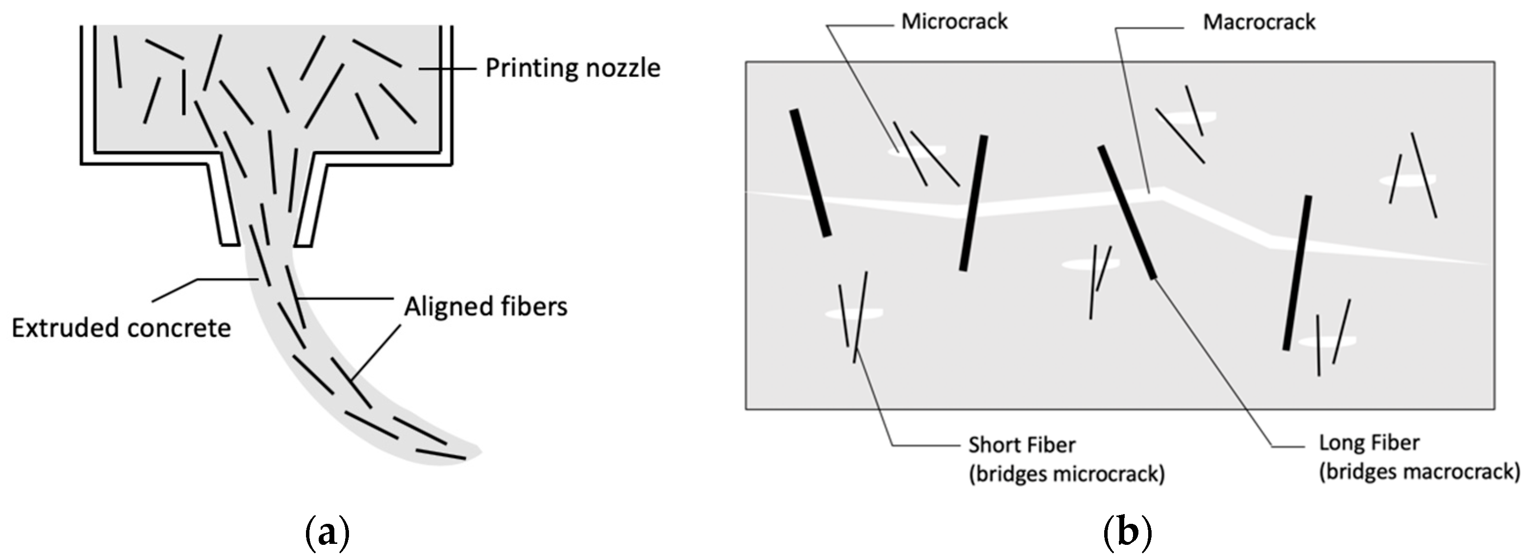
2.1.3. Fiber Reinforcement
2.1.4. Prestressed Cables
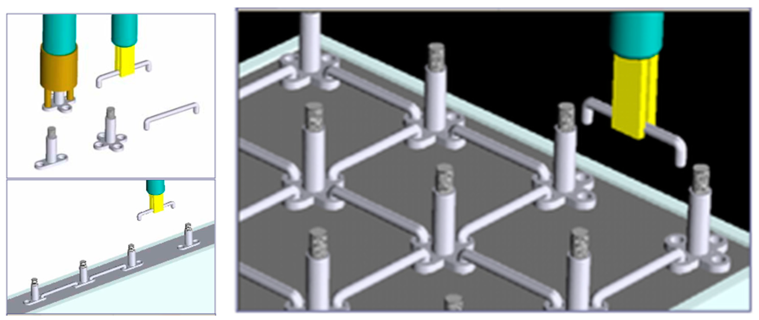
2.1.5. Wire Mesh Reinforcement
2.1.6. Summary of Potential Use in 3DPC
2.2. Reinforcing for Other Materials
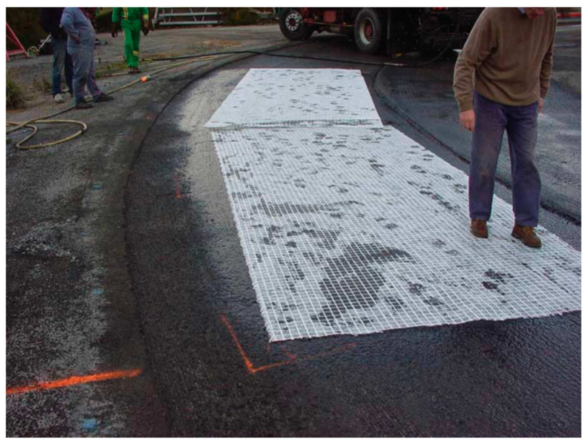
2.2.1. Flexible Asphalt Pavement
2.2.2. Masonry
2.2.3. Glass
2.2.4. Wood
2.2.5. Ceramics
2.2.6. Summary of Potential Use in 3DPC
3. Existing Studies on Reinforcement in 3DPC
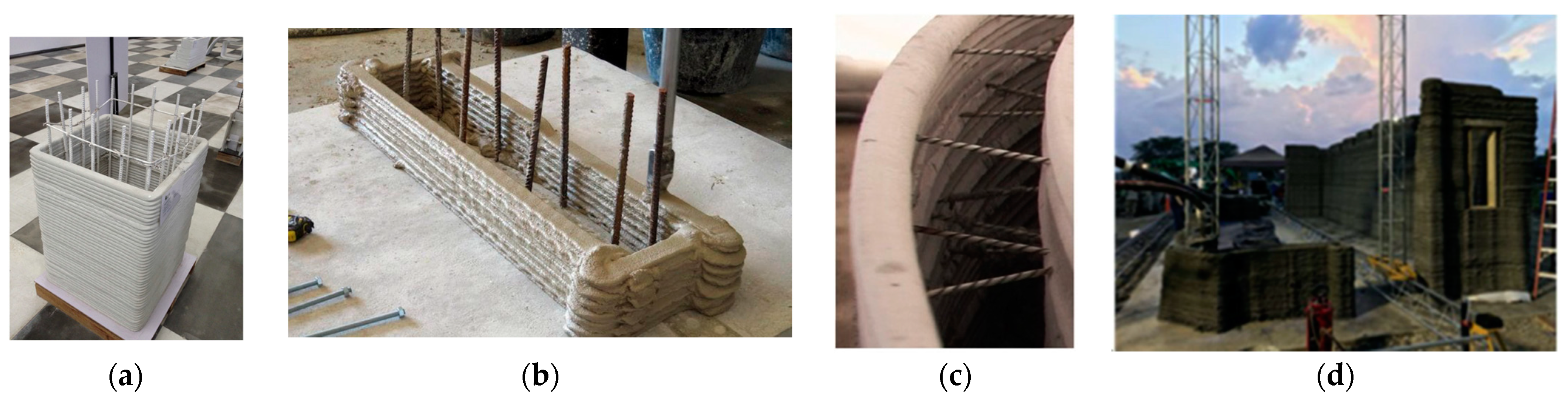
3.1. Pre-Installed and Post-Installed Reinforcement Methods
3.1.1. Reinforcement Methods Adopted by Companies
3.1.2. Other Methods Reported in the Literature
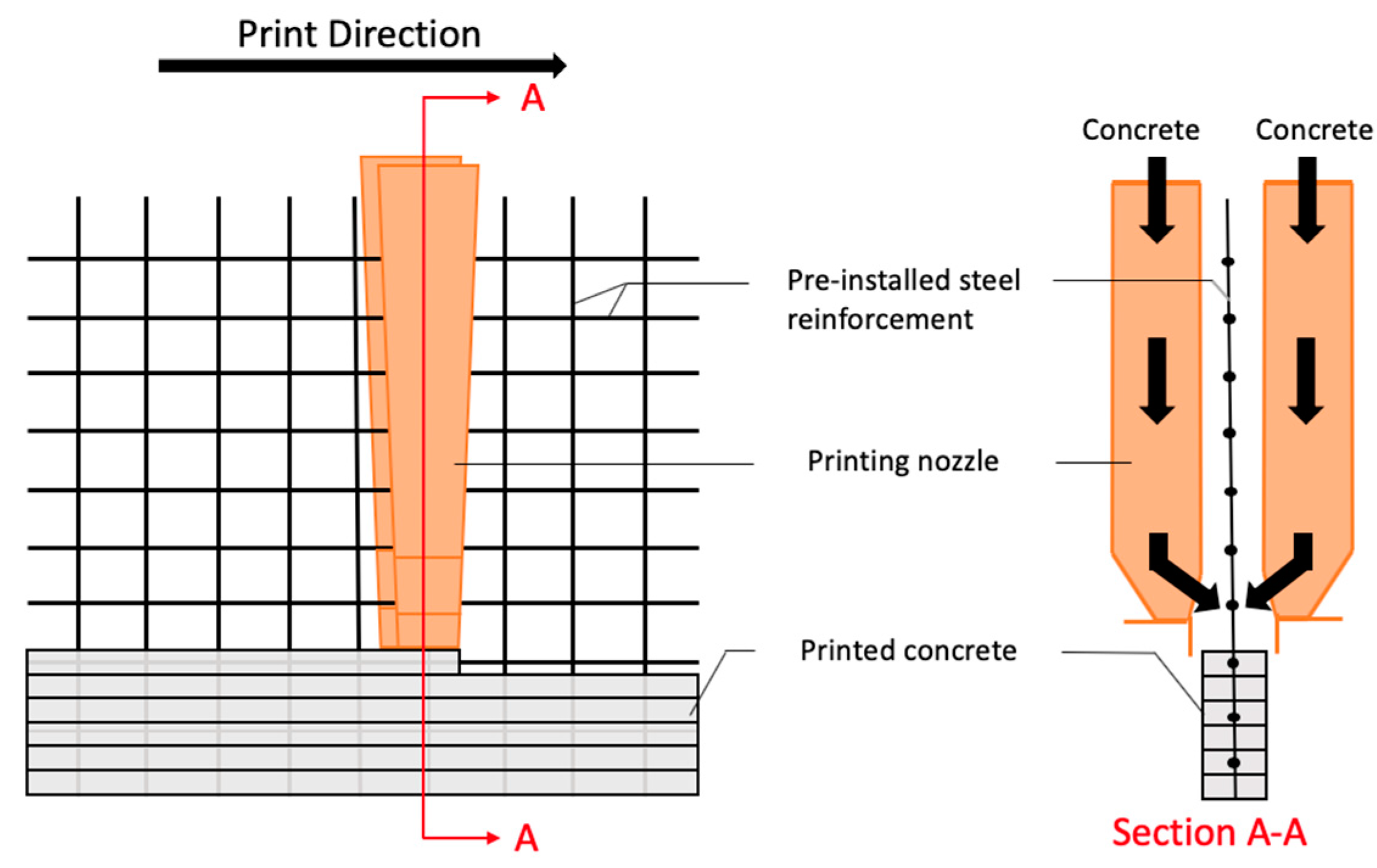
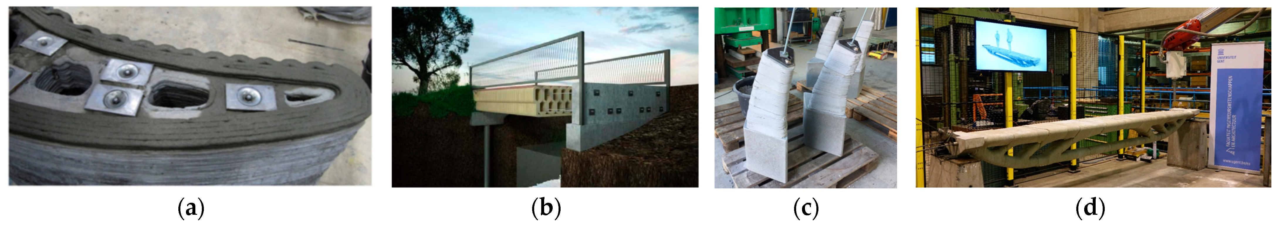
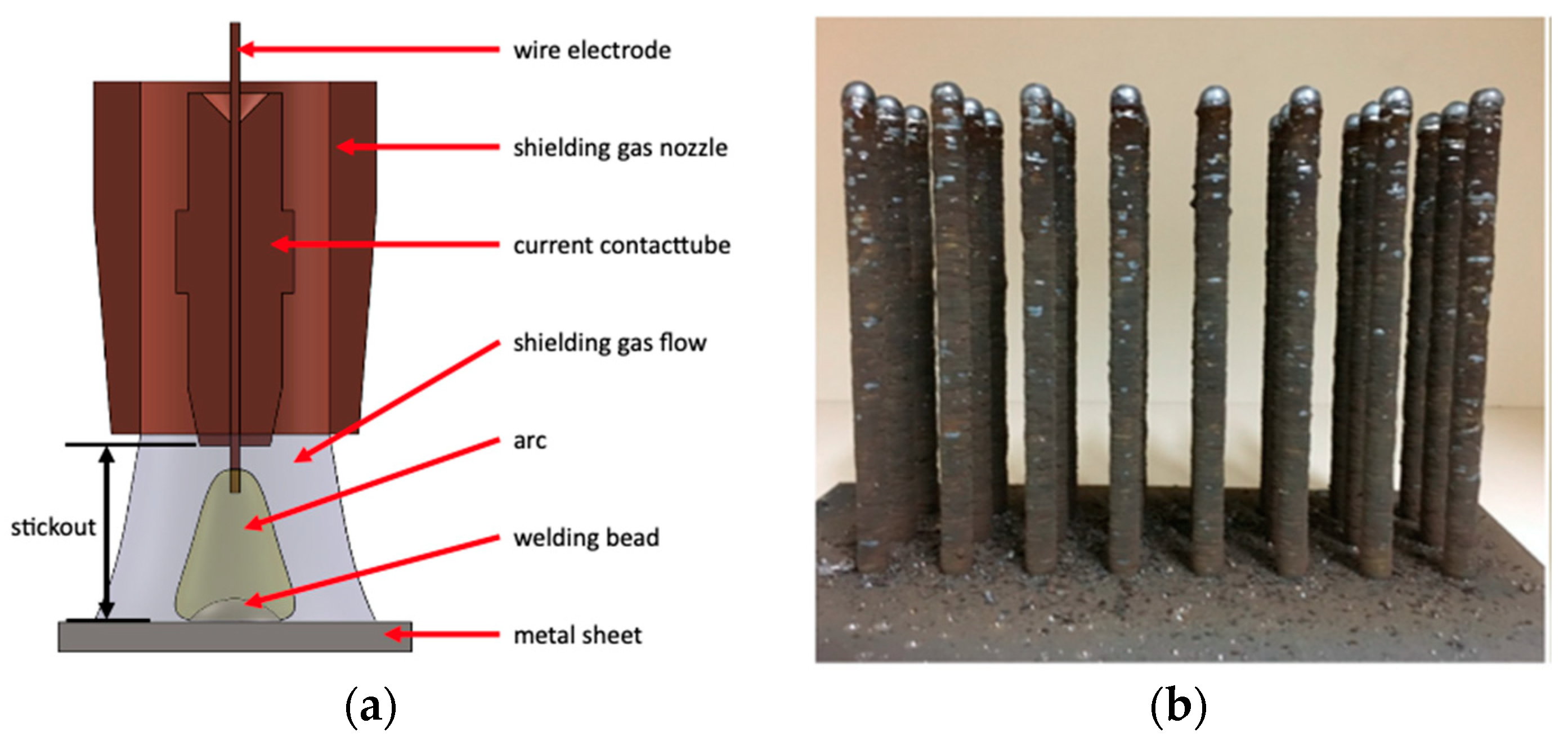
3.2. In-Process Reinforcement Methods
4. Evaluation
4.1. Effectiveness of Current Reinforcement Ideas on 3DPC
4.2. Implementations of Reinforcing Idea for Other Than Concrete in 3DPC
4.3. Shortcomings and Possible Improvements
5. Conclusions
- The favorable characteristics for reinforcement used in printed concrete include (a) less extra labor work and time needed for applying the reinforcement, (b) being easy to fabricate and use at a low cost, and (c) providing a high level of strengthening for specific construction elements.
- No reinforcement method is suitable for all types of construction elements. A more targeted reinforcement strategy will increase the effectiveness of reinforcing.
- Possible improvements for existing reinforcement methods include (a) a novel printing system with multiple robots working separately to print concrete and place reinforcement simultaneously and (b) a combination of different reinforcement methods.
- In future work, the development of suitable reinforcement strategies for printed concrete should follow either of the two directions, (a) applying continuous and stiff reinforcement using robot during printing and (b) maximizing the enhancement of structural performance from discontinuous or flexible reinforcement in printed concrete.
- For the large-scale adoption of 3DPC in the future, design standards for printed concrete as well as code recognitions and/or guidelines to establish equivalency to reinforced concrete through testing is vital. Guidelines are also needed to illustrate applicable analytical equations to calculate structural capacities and standard testing procedures for safety-related performance and serviceability-related expectations. Additionally, the development of 3D modeling software for structural topological optimization is also crucial for using material more effectively.
Author Contributions
Funding
Institutional Review Board Statement
Informed Consent Statement
Conflicts of Interest
References
- Memari, A.; Solnosky, R.; Tufano, J.; Dillen, M. Comparative study on multi-hazard resistance and embodied energy of different residential building wall systems. J. Civ. Eng. Archit. Res. 2014, 1, 367–387. [Google Scholar]
- Hossain, M.A.; Zhumabekova, A.; Paul, S.C.; Kim, J.R. A review of 3D printing in construction and its impact on the labor market. Sustainability 2020, 12, 8492. [Google Scholar] [CrossRef]
- Tao, C.; Kutchko, B.G.; Rosenbaum, E.; Massoudi, M. A Review of Rheological Modeling of Cement Slurry in Oil Well Applications. Energies 2020, 13, 570. [Google Scholar] [CrossRef] [Green Version]
- Tao, C.; Kutchko, B.G.; Rosenbaum, E.; Wu, W.-T.; Massoudi, M. Steady Flow of a Cement Slurry. Energies 2019, 12, 2604. [Google Scholar] [CrossRef] [Green Version]
- American Concrete Institute. ACI 318-19: Building Code Requirements for Structural Concrete: Ccommentary on Building Code Requirements for Structural Concrete (ACI 318R-19); American Concrete Institute: Farmington Hills, MI, USA, 2019. [Google Scholar]
- Andrew, R.M. Global CO2 emissions from cement production. Earth Syst. Sci. Data 2018, 10, 195–217. [Google Scholar] [CrossRef] [Green Version]
- Ghavami, K. Bamboo as reinforcement in structural concrete elements. Cem. Concr. Compos. 2005, 27, 637–649. [Google Scholar] [CrossRef]
- Portnov, G.; Bakis, C.E.; Lackey, E.; Kulakov, V. FRP Reinforcing bars—Designs and methods of manufacture (Review of Patents). Mech. Compos. Mater. 2013, 49, 381–400. [Google Scholar] [CrossRef]
- Fiore, V.; Scalici, T.; Bella, G.D.; Valenza, A. A review on basalt fibre and its composites. Compos. Part B Eng. 2015, 74, 74–94. [Google Scholar] [CrossRef]
- Guide for the Design and (FRP) Bars ACI 440.1R-15. Available online: http://mrg-composites.com/wp-content/uploads/2020/06/Standart_ACI-4401R15.pdf (accessed on 7 December 2021).
- Kudyakov, K.L.; Plevkov, V.S.; Nevskii, A.V. Strength and deformability of concrete beams reinforced by non-metallic fiber and composite rebar. IOP Conf. Ser. Mater. Sci. Eng. 2015, 71, 012030. [Google Scholar] [CrossRef]
- Ceroni, F.; Cosenza, E.; Gaetano, M.; Pecce, M. Durability issues of FRP rebars in reinforced concrete members. Cem. Concr. Compos. 2006, 28, 857–868. [Google Scholar] [CrossRef]
- Memari, A.M.; Lepage, A.; Setthachayanon, J. An experimental study of autoclaved aerated concrete lintels strengthened with externally bonded glass FRP. J. Reinf. Plast. Compos. 2010, 29, 3322–3337. [Google Scholar] [CrossRef]
- Saadatmanesh, H.; Ehsani, M.R. RC Beams Strengthened with GFRP Plates. I: Experimental Study. J. Struct. Eng. 1991, 117, 3417–3433. [Google Scholar] [CrossRef]
- Deuring, M. Bericht Nr.224: “Verstärken von Stahlbeton mit Gespannten Faserverbundwerkstoffen”; EMPA: Dubendorf, Switzerland, 1993. [Google Scholar]
- Wight, R.G.; Green, M.F.; Erki, M.A. Prestressed FRP sheets for poststrengthening reinforced concrete beams. J. Compos. Constr. 2001, 5, 214–220. [Google Scholar] [CrossRef]
- American Concrete Institute. ACI PRC-544.4-18: Guide to Design with Fiber-Reinforced Concrete. Available online: https://www.concrete.org/store/productdetail.aspx?ItemID=544418&Language=English&Units=US_AND_METRIC (accessed on 7 December 2021).
- Zollo, R.F. Fiber-reinforced concrete: An overview after 30 years of development. Cem. Concr. Compos. 1997, 19, 107–122. [Google Scholar] [CrossRef]
- Song, P.; Hwang, S. Mechanical properties of high-strength steel fiber-reinforced concrete. Constr. Build. Mater. 2004, 18, 669–673. [Google Scholar] [CrossRef]
- Raza, S.S.; Qureshi, L.A.; Ali, B.; Raza, A.; Khan, M.M. Effect of different fibers (steel fibers, glass fibers, and carbon fibers) on mechanical properties of reactive powder concrete. Struct. Concr. 2020, 22, 334–346. [Google Scholar] [CrossRef]
- Jhatial, A.A.; Goh, W.I.; Mohamad, N.; Alengaram, U.J.; Mo, K.H. Effect of polypropylene fibres on the thermal conductivity of lightweight foamed concrete. MATEC Web Conf. 2018, 150, 03008. [Google Scholar] [CrossRef] [Green Version]
- Irshidat, M.R.; Al-Nuaimi, N.; Rabie, M. The role of polypropylene microfibers in thermal properties and post-heating behavior of cementitious composites. Materials 2020, 13, 2676. [Google Scholar] [CrossRef]
- Wang, Y.; Wu, H.C.; Li, V.C. Concrete Reinforcement with Recycled Fibers. J. Mater. Civ. Eng. 2000, 12, 314–319. [Google Scholar] [CrossRef]
- Lawler, J.S. Fracture processes of hybrid fiber-reinforced mortar. Mater. Struct. 2003, 36, 197–208. [Google Scholar] [CrossRef]
- PTI. Post-Tensioning Manual; Post Tensioning Institute: Phoenix, AZ, USA, 2006. [Google Scholar]
- American Concrete Institute. ACI PRC-439.5-18: Comprehensive Guide for the Specification, Manufacture and Construction Use of Welded Wire Reinforcement. Available online: https://www.concrete.org/store/productdetail.aspx?ItemID=439518&Language=English&Units=US_Units (accessed on 7 December 2021).
- Ibrahim, H.M. Experimental investigation of ultimate capacity of wired mesh-reinforced cementitious slabs. Constr. Build. Mater. 2011, 25, 251–259. [Google Scholar] [CrossRef]
- Khoshnevis, B. Automated construction by contour crafting—Related robotics and information technologies. Autom. Constr. 2004, 13, 5–19. [Google Scholar] [CrossRef]
- Wu, P.; Wang, J.; Wang, X. A critical review of the use of 3-D printing in the construction industry. Autom. Constr. 2016, 68, 21–31. [Google Scholar] [CrossRef] [Green Version]
- Nguyen, M.; Blanc, J.; Kerzrého, J.; Hornych, P. Review of glass fibre grid use for pavement reinforcement and APT experiments at IFSTTAR. Road Mater. Pavement Des. 2013, 14 (Suppl. 1), 287–308. [Google Scholar] [CrossRef]
- Button, J.W.; Lytton, R.L. Evaluation of fabrics, fibers and grids in overlays. In Proceedings of the Sixth International Conference, Structural Design of Asphalt Pavements, Volume I, Proceedings, University of Michigan, Ann Arbor, MI, USA, 13–17 July 1987. [Google Scholar]
- International Code Council. 2021 International Building Code (IBC): ICC Digital Codes. Available online: https://codes.iccsafe.org/content/IBC2021P1/chapter-21-masonry (accessed on 7 December 2021).
- Franklin, M. ACI 530-11 Building Code Requirements and Specification for Masonry. Academia.edu. (19 August 2020). Available online: https://www.academia.edu/43899269/ACI_530_11_Building_Code_Requirements_and_Specification_for_Masonry (accessed on 6 December 2021).
- Turco, V.; Secondin, S.; Morbin, A.; Valluzzi, M.; Modena, C. Flexural and shear strengthening of un-reinforced masonry with FRP bars. Compos. Sci. Technol. 2006, 66, 289–296. [Google Scholar] [CrossRef]
- Reinforcement, B.M.J. General: ASTM A 951/A 951M. 1. Interior Walls: Hot-dip galvanized, carbon steel, 2, p. 042200-4.
- National Concrete Masonry Association. TEK 12-02B. 2005. Available online: https://pt.scribd.com/document/316367207/TEK-12-02B (accessed on 3 December 2020).
- Brick Industry Association. Tech Notes 44B—Wall Ties for Brick Masonry. 2003. Available online: https://www.gobrick.com/docs/default-source/read-research-documents/technicalnotes/44b-wall-ties-for-brick-masonry.pdf?sfvrsn=0 (accessed on 6 December 2021).
- Memari, A.M.; Solnosky, R.L.; Stallworth, H.L. Experimental Flexural Behavior of a Panelized Reinforced Brick Veneer with FRP Reinforcing on Steel Stud Wall Systems. Pract. Period. Struct. Des. Constr. 2016, 21, 04016011. [Google Scholar] [CrossRef]
- NFPA 80: Standard for Fire Doors and Other Opening Protectives; National Fire Protection Association: Quincy, MA, USA, 2019.
- Fatima, S. Industry Experts Question the Safety of Wired Glass Used in Schools. (25 August 2014). Available online: https://www.theglobeandmail.com/news/national/education/industry-experts-question-the-safety-of-wired-glass-used-in-schools/article20201387/ (accessed on 3 December 2020).
- Memari, A.M.; Behr, R.A.; Kremer, P.A. Dynamic Racking Crescendo Tests on Architectural Glass Fitted with Anchored Pet Film. J. Archit. Eng. 2004, 10, 5–14. [Google Scholar] [CrossRef]
- Bulleit, W. Reinforcement of Wood Materials: A Review. (3 July 1984). Available online: https://wfs.swst.org/index.php/wfs/article/view/832 (accessed on 4 December 2020).
- Plevris, N.; Triantafillou, T.C. FRP-Reinforced Wood as Structural Material. J. Mater. Civ. Eng. 1992, 4, 300–317. [Google Scholar] [CrossRef]
- Triantafillou, T.C.; Deskovic, N. Prestressed FRP Sheets as External Reinforcement of Wood Members. J. Struct. Eng. 1992, 118, 1270–1284. [Google Scholar] [CrossRef]
- Corradi, M.; Mouli Vemury, C.; Edmondson, V.; Poologanathan, K.; Nagaratnam, B. Local FRP reinforcement of existing timber beams. Compos. Struct. 2021, 258, 113363. [Google Scholar] [CrossRef]
- Naslain, R.R. Fiber-Reinforced Ceramic Matrix Composites State of the Art Challenge and Perspective Uni Bordeaux. 2005. Available online: https://pt.scribd.com/document/239327543/Fiber-Reinforced-Ceramic-Matrix-Composites-State-of-the-Art-Challenge-and-Perspective-Uni-Bordeaux (accessed on 3 December 2020).
- Sambell, R.A.J.; Bowen, D.H.; Phillips, D.C. Carbon fibre composites with ceramic and glass matrices. J. Mater. Sci. 1972, 7, 663–675. [Google Scholar] [CrossRef]
- Tiegs, T.N.; Becher, P.F. Alumina-SiC Whisker Composites—Research Gate. (March 2008). Available online: https://www.researchgate.net/publication/227873553_Alumina-SiC_Whisker_Composites (accessed on 4 December 2020). [CrossRef]
- Becher, P.F.; Hsueh, C.; Angelini, P.; Tiegs, T.N. Toughening Behavior in Whisker-Reinforced Ceramic Matrix Composites. J. Am. Ceram. Soc. 1988, 71, 1050–1061. [Google Scholar] [CrossRef]
- Zapata-Solvas, E.; Gómez-García, D.; Domínguez-Rodríguez, A. Towards physical properties tailoring of carbon nanotubes-reinforced ceramic matrix composites. J. Eur. Ceram. Soc. 2012, 32, 3001–3020. [Google Scholar] [CrossRef]
- Lange, F.F.; Velamakanni, B.V.; Evans, A.G. Method for Processing Metal-Reinforced Ceramic Composites. J. Am. Ceram. Soc. 1990, 73, 388–393. [Google Scholar] [CrossRef]
- Asprone, D.; Auricchio, F.; Menna, C.; Mercuri, V. 3D printing of reinforced concrete elements: Technology and design approach. Constr. Build. Mater. 2018, 165, 218–231. [Google Scholar] [CrossRef]
- Asprone, D.; Menna, C.; Bos, F.P.; Salet, T.A.; Mata-Falcón, J.; Kaufmann, W. Rethinking reinforcement for digital fabrication with concrete. Cem. Concr. Res. 2018, 112, 111–121. [Google Scholar] [CrossRef]
- Khoshnevis, B.; Hwang, D.; Yao, K.T.; Yeh, Z. Mega-scale fabrication by Contour Crafting. Int. J. Ind. Syst. Eng. 2006, 1, 301. [Google Scholar] [CrossRef] [Green Version]
- Mechtcherine, V.; Grafe, J.; Nerella, V.N.; Spaniol, E.; Hertel, M.; Füssel, U. 3D-printed steel reinforcement for digital concrete construction—Manufacture, mechanical properties and bond behaviour. Constr. Build. Mater. 2018, 179, 125–137. [Google Scholar] [CrossRef]
- Kreiger, E.L.; Kreiger, M.A.; Case, M.P. Development of the construction processes for reinforced additively constructed concrete. Addit. Manuf. 2019, 28, 39–49. [Google Scholar] [CrossRef]
- CyBe Construction. CyBe Construction. (9 April 2021). Available online: https://cybe.eu/ (accessed on 6 November 2021).
- Apis Cor. Available online: https://www.apis-cor.com/ (accessed on 6 November 2021).
- ICON. Available online: https://www.iconbuild.com/ (accessed on 7 December 2021).
- WinSun. Yingchuang Building Technique (Shanghai) Co., Ltd. (WinSun). Available online: http://www.winsun3d.com/En/ (accessed on 7 December 2021).
- Scott, C. Chinese Construction Company 3D Prints an Entire Two-Story House On-Site in 45 Days—3DPrint.com: The Voice of 3D Printing/Additive Manufacturing. (17 June 2016). Available online: https://3dprint.com/138664/huashang-tengda-3d-print-house/ (accessed on 3 December 2020).
- Hack, N. Mesh-Mould: Differentiation for Enhanced Performance. Available online: https://www.researchgate.net/publication/281966796_Mesh-Mould_Differentiation_for_Enhanced_Performance (accessed on 3 December 2020).
- Wangler, T.; Lloret, E.; Reiter, L.; Hack, N.; Gramazio, F.; Kohler, M.; Flatt, R. Digital Concrete: Opportunities and Challenges. (31 October 2016). Available online: https://letters.rilem.net/index.php/rilem/article/view/16 (accessed on 4 December 2020).
- Hack, N.; Lauer, W.V. Mesh-Mould: Robotically Fabricated Spatial Meshes as Reinforced Concrete Formwork. Archit. Des. 2014, 84, 44–53. [Google Scholar] [CrossRef]
- Shelton, T. Cellular Fabrication: Branch Technology, 2014–Present. Technol. Archit. Des. 2017, 1, 251–253. [Google Scholar] [CrossRef]
- Feng, P.; Meng, X.; Zhang, H. Mechanical behavior of FRP sheets reinforced 3D elements printed with cementitious materials. Compos. Struct. 2015, 134, 331–342. [Google Scholar] [CrossRef]
- Lim, S.; Buswell, R.; Le, T.; Austin, S.; Gibb, A.; Thorpe, T. Developments in construction-scale additive manufacturing processes. Autom. Constr. 2012, 21, 262–268. [Google Scholar] [CrossRef] [Green Version]
- Bulck, L.V. Assembling Structural 3D Concrete Printed Elements (Unpublished Master’s Thesis). Master’s Thesis, Eindhoven University of Technology, Eindhoven, The Netherlands, 2017. [Google Scholar]
- Salet, T.A.; Ahmed, Z.Y.; Bos, F.P.; Laagland, H.L. Design of a 3D printed concrete bridge by testing. Virtual Phys. Prototyp. 2018, 13, 222–236. [Google Scholar] [CrossRef] [Green Version]
- Leal Da Silva, W.; Andersen, T.; Kudsk, A.; Jørgensen, K. 3D Concrete Printing of Post-Tensioned Elements. (16 July 2018). Available online: https://www.ingentaconnect.com/content/iass/piass/2018/00002018/00000007/art00006 (accessed on 4 December 2020).
- Vantyghem, G.; Corte, W.D.; Shakour, E.; Amir, O. 3D printing of a post-tensioned concrete girder designed by topology optimization. Autom. Constr. 2020, 112, 103084. [Google Scholar] [CrossRef]
- Hambach, M.; Rutzen, M.; Volkmer, D. Properties of 3D-Printed Fiber-Reinforced Portland Cement Paste. In 3D Concrete Printing Technology; Butterworth-Heinemann: Oxford, UK, 2019; pp. 73–113. [Google Scholar] [CrossRef]
- Bos, F.P.; Bosco, E.; Salet, T.A. Ductility of 3D printed concrete reinforced with short straight steel fibers. Virtual Phys. Prototyp. 2018, 14, 160–174. [Google Scholar] [CrossRef]
- Van der Krift, C. The Structural Potential of Steel Fibres in 3D-Printed Concrete: Exploring Nonlinear Numerical Strategies for the Analysis of Hardened Fibre Reinforced 3D-Printed Concrete Structures (Unpublished Master’s Thesis). Master’s Thesis, Eindhoven University of Technology, Eindhoven, The Netherlands, 2017. [Google Scholar]
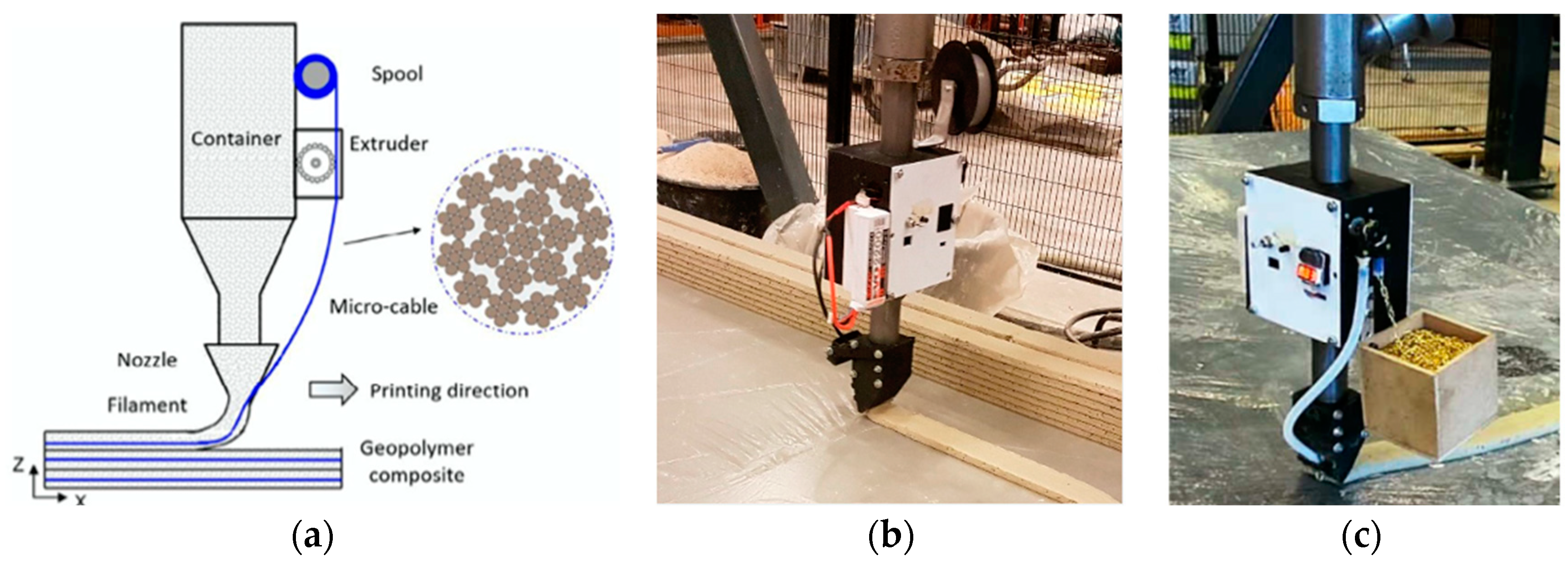
- Ma, G.; Li, Z.; Wang, L.; Bai, G. Micro-cable reinforced geopolymer composite for extrusion-based 3D printing. Materials Letters 2019, 235, 144–147. [Google Scholar] [CrossRef]
- Jutinov, E. 3D Concrete Printing: Research and Development of a Structural Reinforcement System for 3D Printing with Concrete (Unpublished Master’s Thesis). Master’s Thesis, Eindhoven University of Technology, Eindhoven, The Netherlands, 2017. [Google Scholar]
- Bos, F.; Ahmed, Z.; Jutinov, E.; Salet, T. Experimental Exploration of Metal Cable as Reinforcement in 3D Printed Concrete. Materials 2017, 10, 1314. [Google Scholar] [CrossRef] [PubMed] [Green Version]
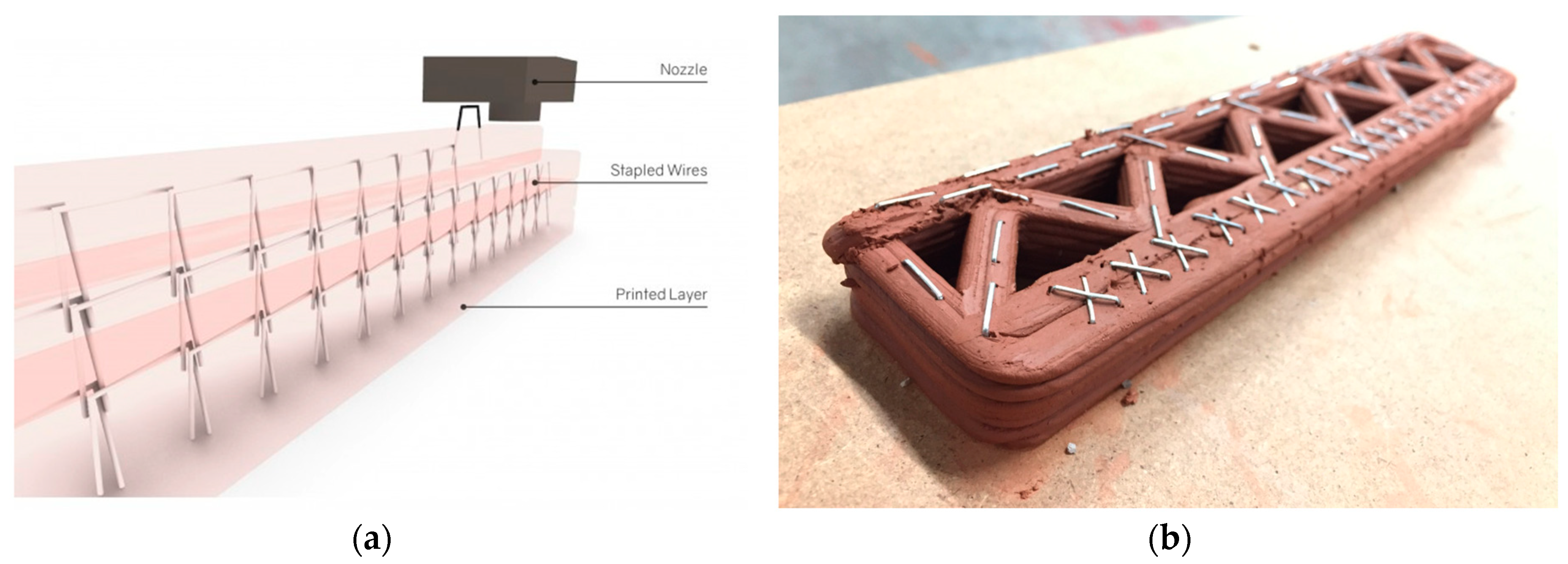
- Geneidy, O. Incorporating A Simultaneous Layer Stapling Process While 3D Printing Structures so as to Complement Their Structural Properties. (20 March 2019). Available online: http://www.iaacblog.com/programs/incorporating-simultaneous-layer-stapling-process-3d-printing-structures-complement-structural-properties/ (accessed on 3 December 2020).
- Geneidy, O.; Kumarji, S.; Dubor, A.; Sollazzo, A. Simultaneous Reinforcement of Concrete While 3D Printing. In RILEM Bookseries Second RILEM International Conference on Concrete and Digital Fabrication; Springer: Cham, Switzerland, 2020; pp. 895–905. [Google Scholar] [CrossRef]
- Marchment, T.; Sanjayan, J. Mesh reinforcing method for 3D Concrete Printing. Autom. Constr. 2020, 109, 102992. [Google Scholar] [CrossRef]


| Reinforcement Methods | Attributes | Drawbacks | Complexity and Energy Consumption | |
|---|---|---|---|---|
| Pre-installed reinforcement | Prefabricated steel or thermoplastic polymer mesh structure (e.g., Mesh Mould) | Increase structural integrity and stability | Application is limited to non-structural components (e.g., interior walls) when thermoplastic polymer mesh is used | Requires long time and equipment to fabricate mesh structure |
| Post-installed reinforcement | Vertical steel rebar (e.g., Contour Crafting) | Increase flexural strength | Not suitable for vertically curved wall | Easy to operate with extra labor need |
| Post-tensioned steel cable | Increase flexural strength and delay crack initiation | More test results are needed to evaluate its effectiveness | Requires long time and equipment to tension cables | |
| External steel rebar | Increase flexural, compressive, and shear strength | Requires long time for post-processing | Requires heavy labor work to assemble external reinforcement system | |
| FRP sheet | Increase flexural strength and ductility | Requires extended fabrication time especially for large concrete members | Requires labor work | |
| In-process reinforcement | Discontinuous reinforcement (e.g., steel, carbon, glass, and basalt fibers) | Increase flexural, compressive, and shear strength. Increase post-cracking stiffness | Not enough strong on its own to use in large concrete members | Easy to operate |
| Continuous reinforcement (e.g., wire rope, steel chain, steel wire) | Increase flexural strength, ductility, and post-cracking stiffness | Not enough strong on its own to use in large concrete members | Requires customized printing system | |
| Staple-like steel wire profile | Increase structural integrity, stability, bonding between adjacent printed filaments, and strengthen the weak area | Needs further development in the future in combining with machine learning to locate weak area | Requires customized nozzle system | |
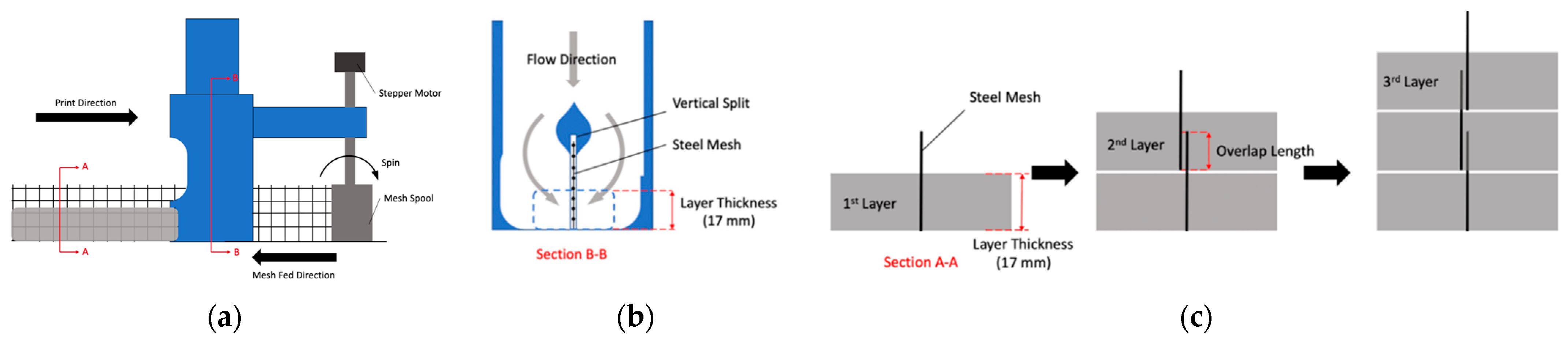
| Vertical steel wire mesh | Increase flexural strength in two directions on the wall plane | Provides limited flexural bending resistance | Requires customized printing system | |
| Steel rebar and steel wire mesh (manually embedded immediately after the printing of each layer) | Increase flexural and shear strength and deflection capacity | Requires labor work during the printing and may not be efficient due to human errors | Easy to operate with extra labor need |
| Construction Elements | Existing Reinforcement Methods | |
|---|---|---|
| Horizontal Element | Slab | Post-tensioned steel cable |
| Steel/FRP rebar and steel wire mesh | ||
| Beam | Post-tensioned steel cable | |
| FRP sheet | ||
| Internal and External steel/FRP rebar | ||
| Vertical Element | Column | Post-tensioned steel cable |
| Steel/FRP rebar | ||
| Wall | Post-tensioned steel cable | |
| Vertical steel/FRP rebar | ||
| Vertical steel wire mesh | ||
| Prefabricated steel or thermoplastic polymer mesh structure |
Publisher’s Note: MDPI stays neutral with regard to jurisdictional claims in published maps and institutional affiliations. |
© 2022 by the authors. Licensee MDPI, Basel, Switzerland. This article is an open access article distributed under the terms and conditions of the Creative Commons Attribution (CC BY) license (https://creativecommons.org/licenses/by/4.0/).
Share and Cite
Wu, Z.; Memari, A.M.; Duarte, J.P. State of the Art Review of Reinforcement Strategies and Technologies for 3D Printing of Concrete. Energies 2022, 15, 360. https://doi.org/10.3390/en15010360
Wu Z, Memari AM, Duarte JP. State of the Art Review of Reinforcement Strategies and Technologies for 3D Printing of Concrete. Energies. 2022; 15(1):360. https://doi.org/10.3390/en15010360
Chicago/Turabian StyleWu, Zhengyu, Ali M. Memari, and Jose P. Duarte. 2022. "State of the Art Review of Reinforcement Strategies and Technologies for 3D Printing of Concrete" Energies 15, no. 1: 360. https://doi.org/10.3390/en15010360
APA StyleWu, Z., Memari, A. M., & Duarte, J. P. (2022). State of the Art Review of Reinforcement Strategies and Technologies for 3D Printing of Concrete. Energies, 15(1), 360. https://doi.org/10.3390/en15010360