Article

Thermal Management of Bone Drilling Based on Rotating Heat Pipe

1
College of Mechanical and Electronic Engineering, Nanjing Forestry University, Nanjing 210037, China
2
College of Mechanical and Electrical Engineering, Nanjing University of Aeronautics and Astronautics, Nanjing 210016, China
*
Author to whom correspondence should be addressed.
Energies 2022, 15(1), 35; https://doi.org/10.3390/en15010035
Submission received: 20 October 2021 / Revised: 9 December 2021 / Accepted: 17 December 2021 / Published: 21 December 2021
(This article belongs to the Section J: Thermal Management)

Abstract

:
Bone drilling is a common surgical operation, which often causes an increase in bone temperature. A temperature above 47 °C for 60 s is the critical temperature that can be allowed in bone drilling because of thermal bone osteonecrosis. Therefore, thermal management in bone drilling by a rotating heat pipe was proposed in this study. A new rotating heat pipe drill was designed, and its heat transfer mechanism and thermal management performance was investigated at occasions with different input heat flux and rotational speed. Results show that boiling and convection heat transfer occurred in the evaporator and film condensation appears in the condenser. The thermal resistance decreases with the increase of the rotational speed at the range from 1200 to 2000 rpm and it decreases as the input heat flux rises from 5000 to 10,000 W/m2 and increases at 20,000 W/m2. The temperature on the drill tip was found to be 46.9 °C with an input heat flux of 8000 W/m2 and a rotational speed of 2000 rpm. The new designed rotating heat pipe drill showed a good prospect for application to bone drilling operations.

Graphical Abstract

1. Introduction

Bone drilling is a common surgical operation that creates holes in the bone by using a twist drill bit [1]. It is widely applied in fracture fixation [2], cochlear implant installation [3] and dental implantation [4]. During bone drilling, a major part of the energy that consumed while machining is converted into heat. Part of the heat is discharged via chips, while a greater portion enters the drill bit and the bone. Because of the low thermal conductivity of bone (0.16–12.8 W·m−1·K−1 [5,6,7]), the drilling heat accumulates in the machining zone, causing a bone temperature rise [8]. The incidence of thermal necrosis and irreversible damage to the bone increases while the bone temperature reaches the critical value of 47 °C and maintains for 60 s, which will damage the soft tissues, weaken the interaction between the screw and bone, increase the possibility of complication, operation failure or prolonged healing time [9,10,11].
In order to solve the problems caused by the drilling heat, some research has been conducted to reduce the extent of temperature rise. This research can be classified into two aspects. The first aspect is the drilling parameters, e.g., the rotational speed, the drill diameter and the combination of ultrasonic vibration. Shakouri et al. studied the drilling temperature with rotational speeds from 1000 to 18,000 rpm on a bovine femur and found that only the rotational speed of 7000 rpm and speed of 11,000 rpm resulted in minimum extent of bone temperature rise [12]. Since bone is an anisotropic material [13], the optimal rotational speed that can reduce the bone temperature is difficult to choose during real surgical operation. Several studies showed that the bone temperature is also affected by the drill diameter [14,15,16]. Augustin et al. pointed out that the thermal osteonecrosis is more significant with the drill diameter of ≥4.5 mm [2]. Therefore, the control of bone drilling temperature with big drill diameter is more urgent. Considering the outstanding performance of ultrasonic vibration in reducing the machining temperature, it was applied in the bone drilling by some researchers; the extent of bone temperature rise was minimized [17,18]. Another aspect is the coolant kinds and coolant supply methods. Augustin et al. limited the maximum bone temperature at about 46.3 °C by using an open-loop internal cooling system [2]. Gok et al. designed a closed-loop internal reservoir in the drill and reduced the bone temperature from the osteonecrosis level by 20–25% [19,20]. Meanwhile, some research has tried to minimize the bone temperature by using different types of coolants, in which gas as CO2 or N2 and liquid as normal saline or water are most commonly applied [21]. The cooling effect of the coolant is considerable while its wide application in the orthopedic surgery is confined because of the risk of infection and the special equipment that required to supply the coolant.
In fact, one thing that has been overlooked is that the drill can also act as a cooling agent in the bone drilling process. Only a few studies have reported the influence of the initial drill temperature on thermal management of bone drilling [22,23]. Lee et al. studied the cooling effect of the drill matrix by lowering the initial drill temperature; results showed that the temperature of the contacted bone surface can be lowered [24]. However, the initial temperature of the drill was set as 0 °C, which is not applicable in real bone drilling situations.
Thermal management using heat pipes has become a significant method in past decades. Heat pipes transfer heat through the phase changes of the working fluid inside the pipe without any extra power. Heat pipes have been studied in various possible applications, such as electronics cooling [25], turbine blade cooling [26] and grinding heat management [27]. Research has shown that the thermal management with heat pipes has a great prospect in energy saving and green manufacturing. However, it has never been applied in bone drilling. From the perspective of dissipating heat by the drill matrix, the high heat transfer capacity of rotating heat pipe and considering its safety advantages without coolant in surgery, a new method that incorporate a rotating heat pipe in the drill was proposed in this paper.
The object of this study is to design the structure of the rotating heat pipe drill (RHPD) and analyze the heat transfer characteristics in the thermal management process by CFD modeling [28]. Factors as input heat flux and rotational speed of the rotating heat pipe are studied. The present study aims to provide a prospect of rotating heat pipe for thermal management of bone drilling with lower incidence of thermal necrosis and the related complications.

2. Design of Rotating Heat Pipe Drill

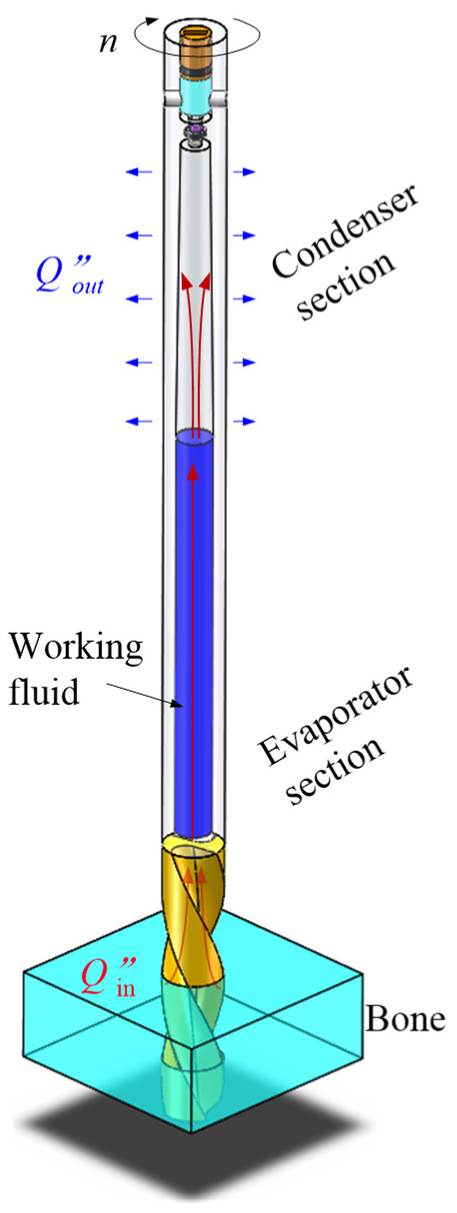
2.1. Heat Transfer Principle of Rotating Heat Pipe Drill

During bone drilling, a major part of the energy that consumed while drilling is converted into heat. Part of the heat is discharged via chips, while a greater portion accumulates in the contact zone between drill bit and the bone. Therefore, the contact part on the drill was considered as the evaporator section, as shown in Figure 1. The upper end is the condenser section, which is cooled by the air while rotating. During drilling, the heat is transferred to the working fluid by thermal conduction through the drill matrix. Because of the high vacuum in the heat pipe, the liquid in the evaporator turns into vapor at a low saturate temperature. Due to the pressure gradient in the vapor phase, the vapor flows to the condenser, where it condenses and flows black to the evaporator driven by the component of centrifugal force and the gravity, thus forming the thermodynamic cycle and transferring heat from the contact zone continuously.

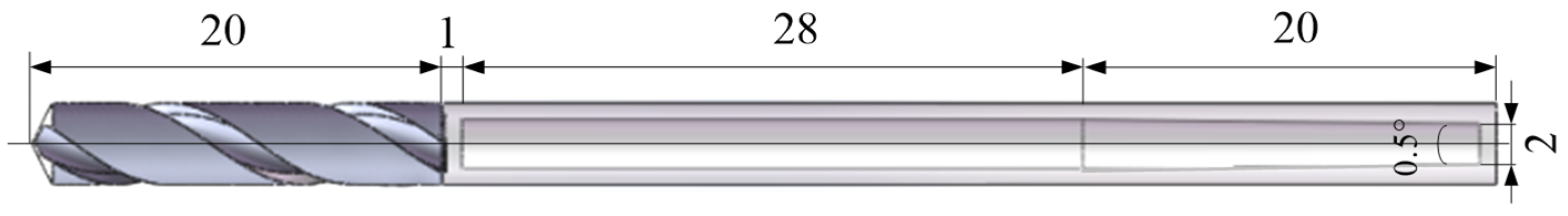
2.2. Design of Rotating Heat Pipe Drill

As the rotating heat pipe works, the working fluid evaporates and the steam flows from the evaporator to the condenser due to the pressure gradient. If the steam flow rate inside the heat pipe is higher than 0.2 Mach number, its compressibility cannot be ignored, and this fluid compression effect will lead to a high axial temperature gradient, thus reducing the overall heat transfer performance of the heat pipe. To ensure the heat transfer performance of the rotating heat pipe, the steam velocity should be controlled under 0.2 Mach number [29]; therefore the minimum inner diameter of the rotating heat pipe drill can be determined by
M = Q m a x A V ρ V L H L V k V C V T V 0.2
where Q m a x is the maximum heat that goes into the drill, ρ V is the vapor density, L H L V refers to the latent heat from liquid to vapor, k V refers to the specific heat ratio of vapor, C V is the vapor constant and T V is the vapor temperature. A V refers to the area of the rotating heat pipe which is calculated as
A V = π d 2 4
A heat input of 85 W was considered at the tips of the drill [30] and with about 30% of the heat that enters the drill [31]. Thus, the minimum inner diameter can be calculated
d 1.881   mm
Therefore, an inner diameter of 2 mm was determined.
In order to ensure the strength of the wall, the maximum working pressure should be lower than the allowable stress of the drill material, which can be expressed as
P 2 [ σ ] δ d 0 δ
where δ is the wall thickness. For the normal temperature heat pipe, distilled water is chosen as the working fluid because of its appropriate working temperature, which is also safer and more environmentally friendly in bone drilling compared to the other working fluid. An extreme pressure of 1.013 × 10 5   Pa is supposed to guarantee the strength of the drill in case of poor vacuum condition. Therefore, the minimum wall thickness can be calculated according to Equation (4)
δ 0.743   mm
Therefore, minimum wall thickness of 1 mm was selected.
The heat transfer in the condenser can be seen as heat conduction through a single cylinder adapted from Yang et al. [32], as shown in Figure 2. The thermal resistance through the condenser wall can be calculated as
R w = l n ( d o / d i ) 2 π λ L c
where d o and d i are the outer and inner diameter of the condenser, λ is the thermal conductivity of the drill material, and L c is the length of the condenser. Usually, the thermal resistance of the evaporator is on the order of 10 1 K/W. To ensure the thermal balance between condenser and evaporator, the thermal resistance in the condenser should be in the same magnitude, so the minimum length of the condenser can be calculated as
L c 17.73   mm
Therefore, the length of the condenser is determined as 20 mm.
In the condenser, Nusselt model of film condensation [33] is applied. The average heat transfer coefficient can be calculated as
h ¯ c = 0.943 [ ρ L 2 r c ω 2 sin θ λ L 3 L H f g μ L L c Δ T ] 0.25
To ensure the thermal balance, the heat goes into the evaporator should be transferred to the outside of the condenser, where the heat goes out of the condenser can be calculated as
Q o u t = h ¯ c A c Δ T
where A c is the area of the condenser. According to Equations (8) and (9), the inner taper angle in the condenser is derived to be higher than 0.49°, so the taper angle was determined as 0.5°.
Therefore, the structure and the main dimensions of the RHPD can be determined and shown in Figure 3. The rotating heat pipe was embedded in the drill matrix, the length of the evaporator and the condenser is 28 and 20 mm, respectively.

3. Simulation Details

3.1. Solution Methods

In this paper, the heat transfer characteristics in the RHPD was simulated using CFD method by Fluent 16.2. Volume of Fluid (VOF) method was applied in the simulation; liquid was identified as the primary phase; vapor was identified as the second phase. As a cell is filled with liquid phase, then the volume fraction of liquid equals to 1 ( α L = 1 ). As a cell is filled with vapor phase, then α L = 0. When a cell is filled with a mixture of both liquid and vapor, then 0 < α L < 1.
The governing equations used for the heat and mass transfer process in the RHPD are the Navier–Stokes equations [34,35]. The continuity equation is
· ( α L ρ V u ) = t ( α L ρ L ) + S m
Sm refers to the mass source term for both evaporation and condensation [34,35]. As the working fluid evaporates, the phase changes from liquid to vapor; therefore, the mass of the liquid decreases while the mass of the vapor increased, which can be derived by Equation (11) and Equation (12), respectively.
S M L = 0.1 ρ L α L T m i x T s a t T s a t
S M V = 0.1 ρ V α V T m i x T s a t T s a t
As the vapor condenses, the phase changes from vapor to liquid; thus the corresponding mass change can be derived by Equations (13) and (14).
S M L = 0.1 ρ L α L T s a t T m i x T s a t
S M V = 0.1 ρ V α V T s a t T m i x T s a t
The momentum equation used for the simulation is shown in Equation (15)
t ( ρ u ) + · ( ρ u ¯ u ) = ρ g p + [ μ ( u + u T ) 2 3 μ · u I ] + F C S F + S m
where F C S F is the surface tension between the vapor and the liquid phase according to Brackbill [36].
F C S F = 2 σ L V α L ρ L C V α V + α V ρ V C L α L ρ L + ρ V
σ L V is the coefficient of surface tension between liquid and vapor phase. C L refers to the surface curvature.
Sm refers to the momentum source term, it is determined by the centrifugal force in rotating heat pipe as shown in Equation (17).
S m = ρ r 2 ω
The energy equation is shown in Equation (18).
t ( ρ e ) + · ( ρ e u ) = · ( k · T ) + · ( ρ u ) + S E
S E refers to the energy sources during the phase change are calculated by Equations (19) and (20) for evaporation and condensation, respectively.
S E E = 0.1 ρ L α L T m i x T s a t T s a t L H
S E C = 0.1 ρ V α V T s a t     T m i x T s a t L H
As distilled water was chosen as the working fluid, L H is calculated by the local saturation temperature according to the physical properties of water:
L H = 3   ×   10 6 1.2682   ×   10 3 T s a t + 1.8106 T s a t 2
All the source terms are calculated by embedding the user defined functions (UDFs) in Fluent.

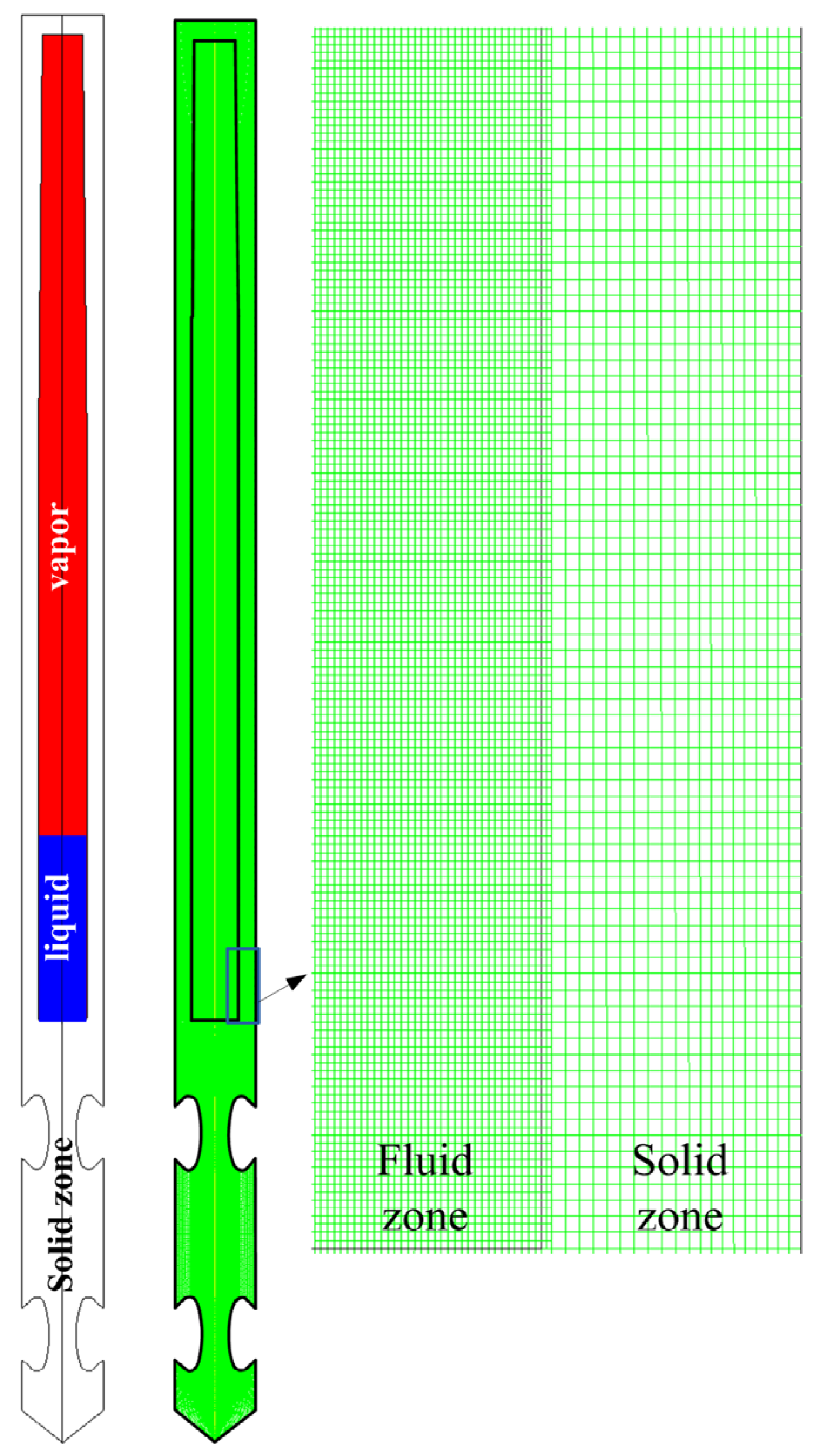
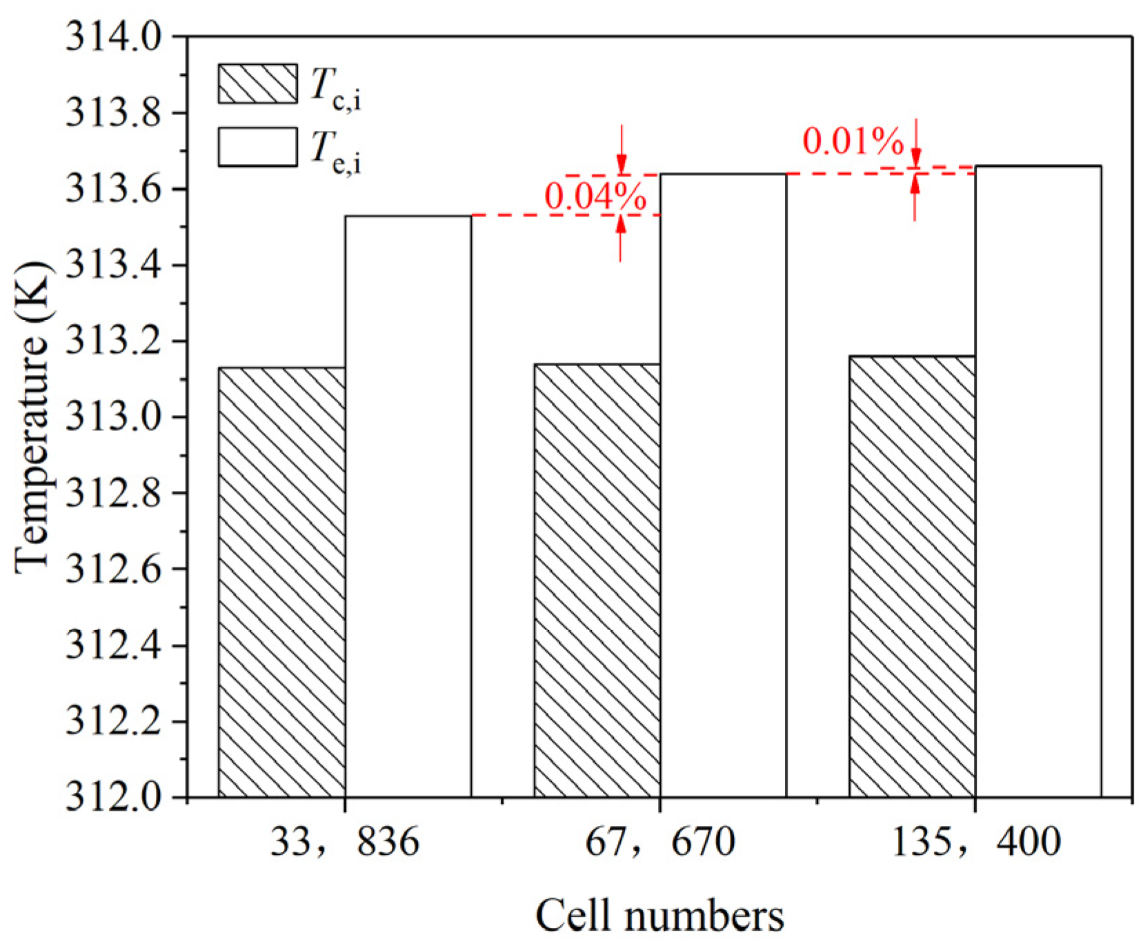
3.2. Simulation Model for RHPD

The simulation model for RHPD is shown in Figure 4, which consists of two domains, including the solid zone and the fluid zone. At the beginning of the simulation, a liquid pool is patched in the fluid zone, which is colored in blue. The other part of the fluid zone is defined as vapor and colored in red. During simulation, constant heat flux was applied on the tips, convection heat transfer coefficient was applied on the outer wall of the condenser and heat insulation was defined for the other walls. The simulation was initialized at 313.15 K with a saturate pressure of about 7381 Pa.
Simulation with different mesh cells of 33,836, 67,670 and 135,400 are compared in preliminary study, as shown in Figure 5. More refined grid was set in the fluid zone than the solid zone. Results show that the average temperature in the condenser is similar for different mesh size, while the average temperature in the evaporator shows a little difference, which might be attributed to the convection in the liquid area. Since the difference is lower than 0.05% for the meshes applied, mesh with 67,670 cells were applied to ensure the modeling accuracy and save the computational time in the meanwhile.
Green–Gauss cell based and body force weighted discretization were selected for volume fraction and pressure interpolation scheme, respectively. Bounded second order implicit for transient formulation was selected. Residuals of the order of 10−6 were set as the convergence criteria for the energy, mass and velocity components. Transient simulation with a time step of 0.00001 s was performed to simulate the heat and mass transfer process of the RHPD. The simulation model is validated in comparison with the results by Eschweiler et al. [37] ( N u = 0.15 R a 0.363 ) and Fei et al. [38] ( N u = 0.133 R a 0.375 ) . The maximum difference is within 10%, as shown in Figure 6.

4. Results and Discussion

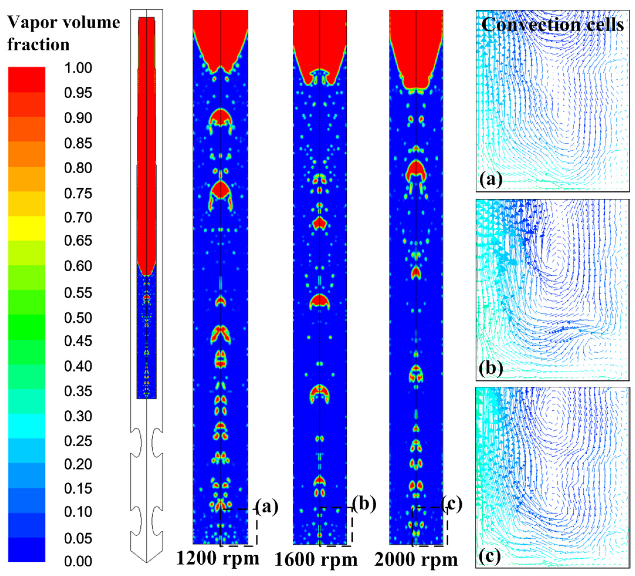
4.1. Heat Transfer Process in the RHPD

Phase change process and fluid flow condition in the RHPD was firstly studied with a filling ratio of 22%, rotational speed of 2000 rpm and an input heat flux of 8000 W/m2. The filling ratio applied in this study was referenced from Xie [39]. The phase and the velocity in the RHPD are shown in Figure 7. Both boiling and convection heat transfer could be found in the evaporator section. It should be noticed that the boiling bubbles mainly occurred near the center axis of the drill. This is because the local pressure near the center axis was lower under the rotating condition, which contributes to lower saturate temperature there. The bubbles moved up quickly toward the condenser section because of the buoyancy, which could be judged by the velocity vector in the center zone. The bubbles gradually grew larger as they moved upward due to the lower local pressure. At the bottom and near the wall area of the evaporator, convection cells could also be found, which further contributes to the heat transfer of the drill. In addition, the heat transfer process in the condenser of the RHPD was found to be a filmwise condensation process, which is consistent with the results by Wang [40].
The temperature contours at different times are shown in Figure 8. The case was calculated at a rotational speed of 2000 rpm and an input heat flux of 8000 W/m2. It can be clearly seen that the heat was conducted to the evaporator through the drill matrix. As the heat went into the fluid area (at about 0.2 s), the working fluid absorbed the heat and evaporated. Because of the high vacuum in the RHPD, the working fluid boils under a low saturate temperature. Because of the lower pressure along the center line while the drill rotates, the bubbles concentrated in the center (see in Figure 7). At about 0.3 s, the boiling bubbles moved up to the condenser quickly, causing a local temperature rise along the center line. The temperature in the rotating heat pipe thus grew higher than that in the side walls, suggesting a better heat transfer capacity of the rotating heat pipe compared to the side drill matrix. As the vapor flowed out of the liquid and reached the condenser, it condensed and exchanged heat with the cold condenser wall (at about 0.8 s). As time went on, the heat exchange process took place along the entire condenser, and thus the thermal dynamic circle formed. The temperature contours reached a steady state at about 4 s.

4.2. Heat Trasnfer Capacity of the RHPD

The heat transfer capacity of the RHPD under different input heat flux and different rotational speed was analyzed by the thermal resistance inside the rotating heat pipe and the temperature distributions along the outer wall of the drill matrix (A-A line, shown in Figure 9) and the center axis (B-B line). The thermal resistance in the rotating heat pipe was defined by the following equation.
R = T e i T c i Q  
where T e i and T c i are the average temperature along the center line (B-B).

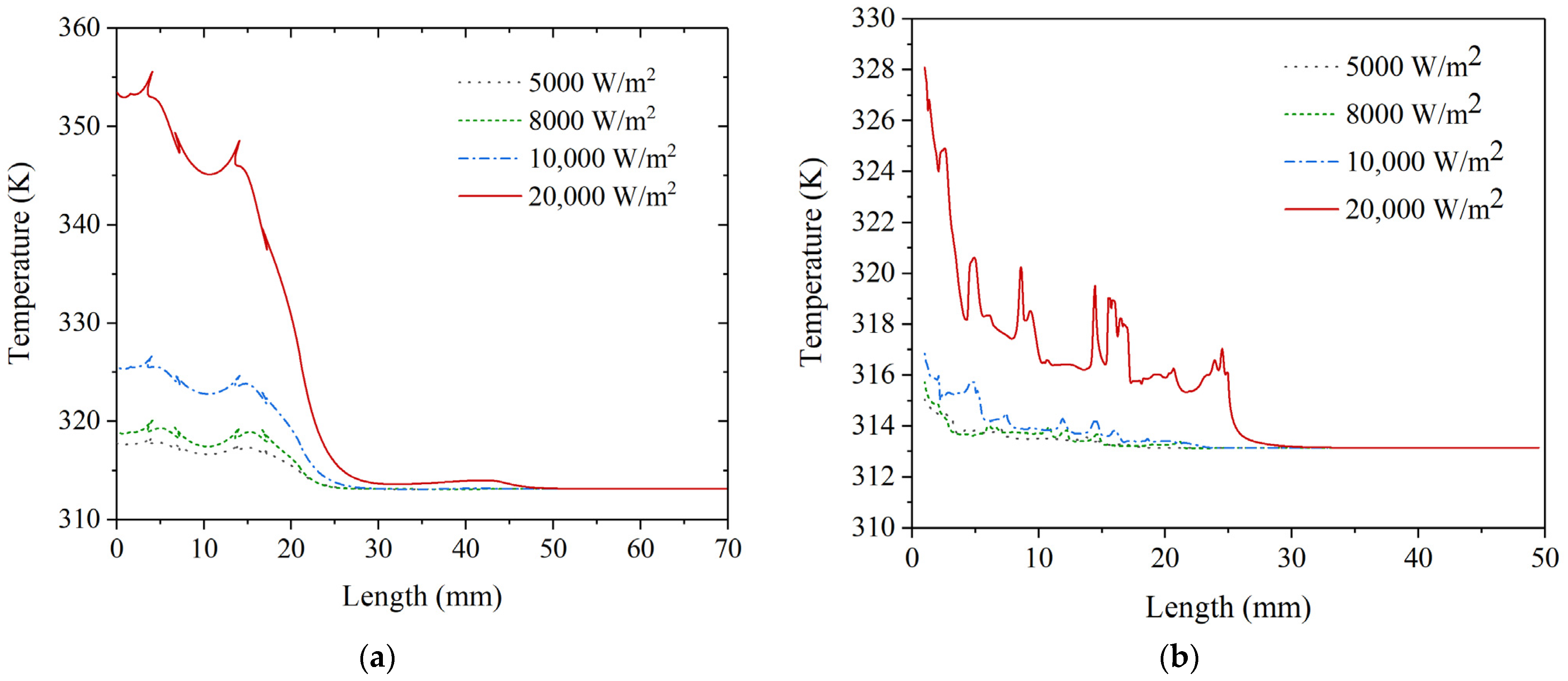
4.2.1. Effect of Input Heat Flux

The thermal resistance for input heat flux of 5000, 8000, 10,000 and 20,000 W/m2 is shown in Figure 10. The simulations were conducted at a rotational speed of 2000 rpm. As the heat flux increased from 5000 to 10,000 W/m2, the thermal resistance decreased from about 0.0287 K/W to about 0.0241 K/W, which decreased by about 19%. In order to find out the reason for this result, the phase distribution and the velocity vectors in the evaporator are displayed in Figure 11. More intense boiling and convection was found in the evaporator as the input heat flux rose. However, as the heat flux increased to 20,000 W/m2, the thermal resistance rose sharply by about 68%. The remarkable deterioration of the heat transfer performance should be attributed to the partial “dry-out” in the evaporator.
The temperatures along the outer wall (A-A line) and the center axis (B-B line) of the RHPD are displayed in Figure 12a,b, respectively. The temperature along the cutting surface of the drill represents the temperature in the contact zone. The maximum temperature of about 355.5 K (about 82.4 °C) occurred at the tip of the drill as a heat flux of 20,000 W/m2 was applied. The value is much higher than the allowable bone drilling temperature of 47 °C, therefore, the drill designed in this study is not available in situations with a heat flux of 20,000 W/m2. As the heat flux of 10,000 W/m2 was applied, the maximum temperature of about 53.4 °C and the average temperature of about 44.7 °C was found on the cutting surface of the drill. Although the average temperature was lower than the critical value, the maximum temperature on the drill tip still exceeded the point. As the heat flux decreased to 8000 W/m2, the maximum temperature on the tip was about 46.9 °C, which is right on the permit point. The average value on the drilling surface was about 42.3 °C. Therefore, heat flux under 8000 W/m2 has been proven to be available for the RHPD designed in this study.
In Figure 12b, the temperatures along the center line obviously fluctuated, which was because of the boiling and forced convection in the liquid. As the input heat flux was 20,000 W/m2, the maximum temperature and average temperature in the evaporator was about 54.9 °C and 44.2 °C, respectively, which is much higher than the boiling point under initial saturate temperature of 40 °C; therefore, “dry-out” of the working fluid occurred in the evaporator.

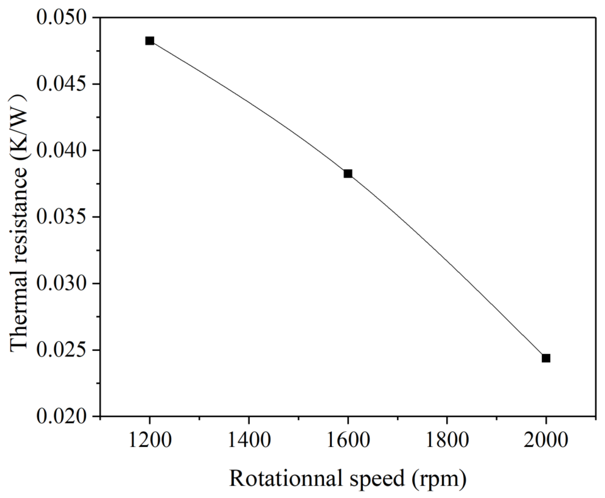
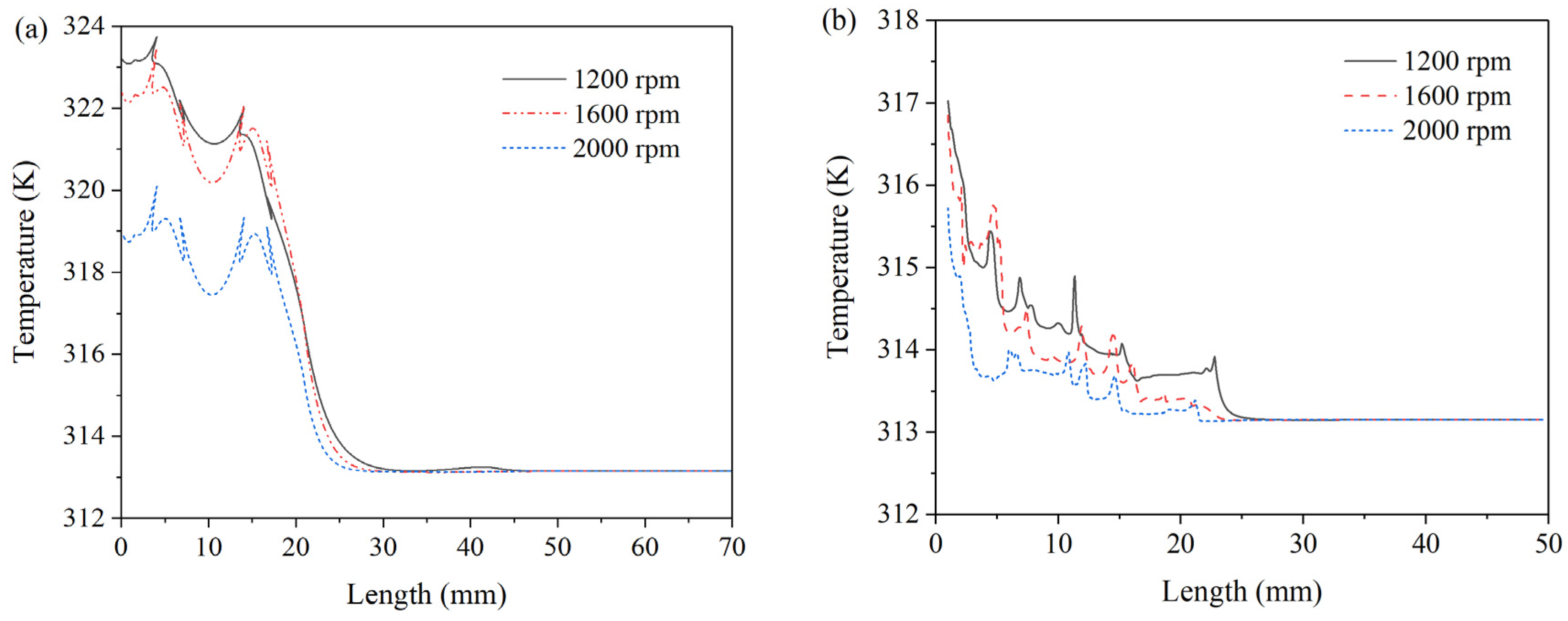
4.2.2. Effect of Rotational Speed

The heat transfer performance of the RHPD was also studied under a low rotational speed from 1200 to 2000 rpm. The simulations were conducted at an input heat flux of 8000 W/m2. As shown in Figure 13, the thermal resistance decreased with the increase of the rotational speed, which is in accordance with the result by Fei et al. [41]. As the rotational speed increased from 1200 to 2000 rpm, the thermal resistance in the rotating heat pipe decreased from about 0.0482 K/W to 0.0244 K/W. In order to find out the reason for this result, the phase distribution and the velocity vector in the rotating heat pipe were analyzed and are shown in Figure 14. Both boiling and convection can be found for all the three cases; besides, more convection cells are found for the case with rotational speed of 2000 rpm. Although boiling was suppressed as the rotational speed increased, convection could be enhanced by the higher centrifugal acceleration. The result of this contradiction turned out to be a better heat transfer performance in the range of the rotational speed investigated in this study.
The temperature distribution along the outer wall and the center line is shown in Figure 15a,b, respectively. The maximum temperature on the drill tip decreased from 50.5 °C to 46.9 °C as the rotational speed increased from 1200 to 2000 rpm. Although the average temperature along the drilling surface remained at 43.6 °C at 1200 rpm, the maximum temperature value of 50.5 °C is still much higher than the critical bone drilling temperature. The temperature along the center line shows a more violent fluctuation in the evaporator section because of the moving bubbles and the convection movement in the liquid layer.

5. Conclusions

In this paper, a new rotating heat pipe drill was designed. CFD simulations were complemented for analysis of its thermal management performance. The main conclusions can be drawn as follows:
(1)
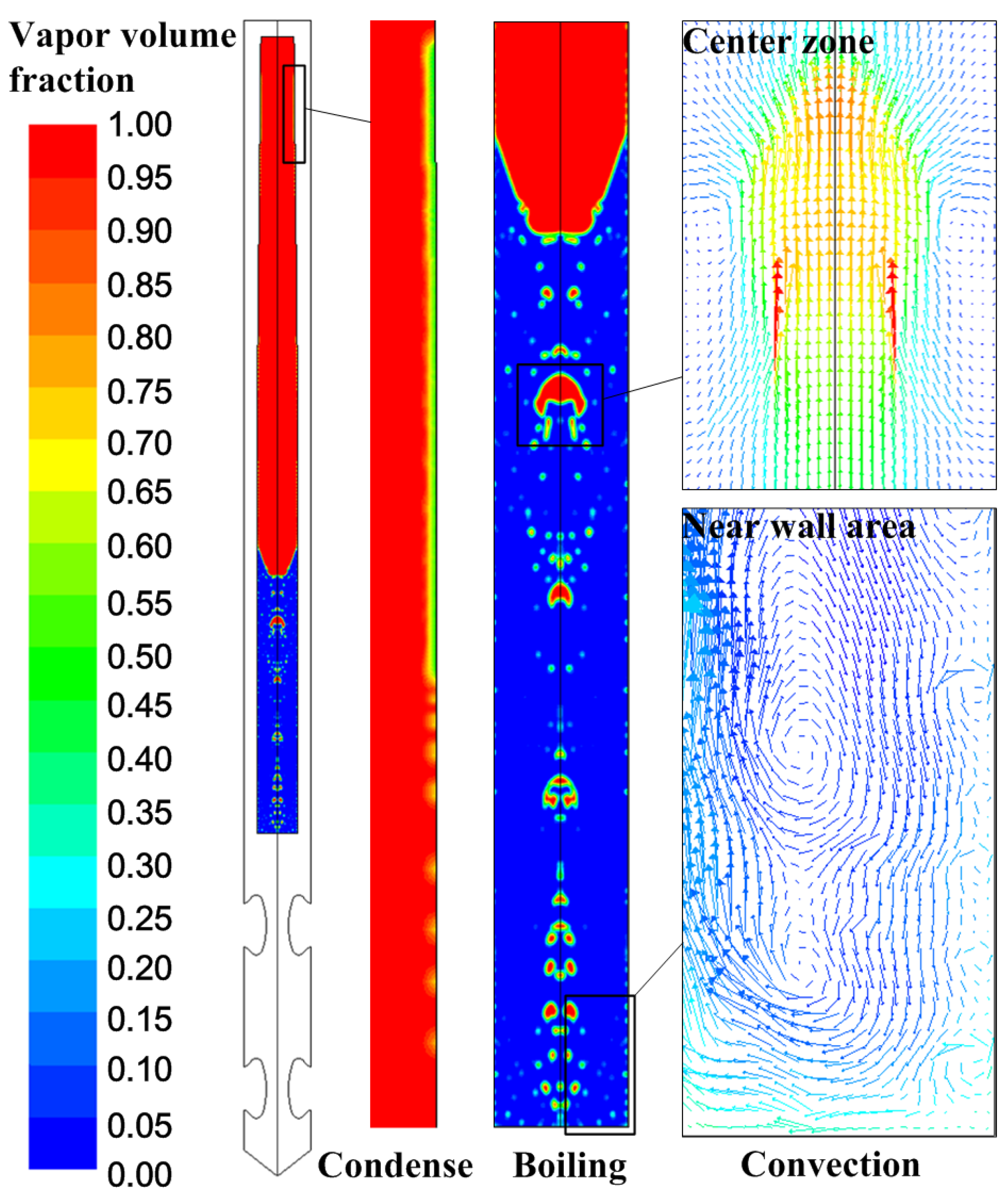
Boiling and convection heat transfer was found to be the main heat transfer mechanism in the evaporator. Film condensation turned out to be the heat transfer regime in the condenser.
(2)
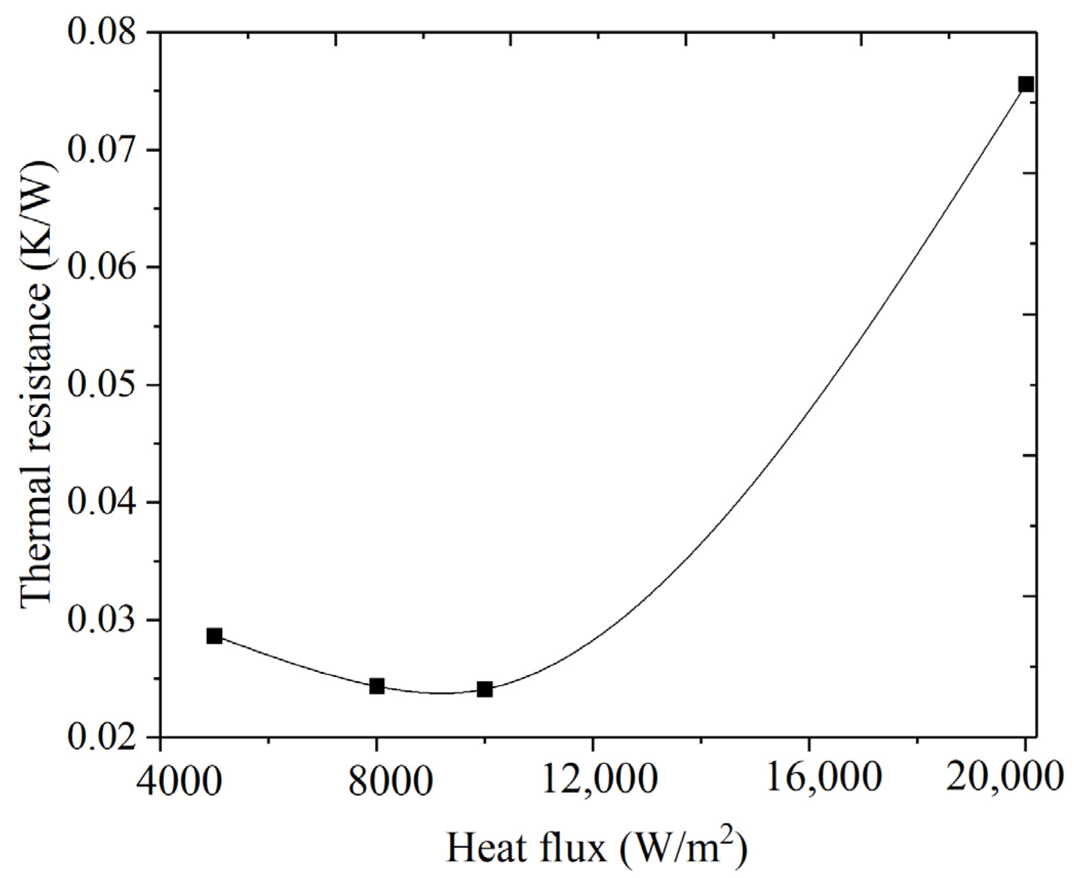
An ideal bone drilling temperature of 46.9 °C and a thermal resistance of 0.0244 K/W was found with an input flux of 8000 W/m2 and a rotational speed of 2000 rpm.
(3)
The thermal resistance decreased with the increase of the rotational speed at the range from 1200 to 2000 rpm because of more intense convection heat transfer.
(4)
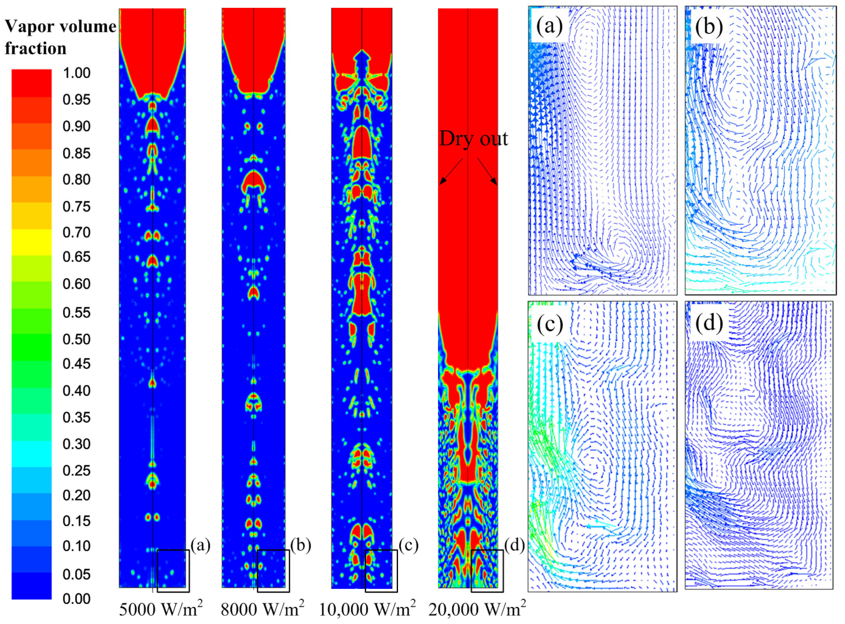
The thermal resistance decreased as the input heat flux rose from 5000 to 10,000 W/m2 due to more intense boiling and convection heat transfer, while it increased at 20,000 W/m2 because of the appearance of dry-out of the working fluid.
(5)
The phase change heat transfer in the rotating heat pipe turned out to be much faster and better than the heat conduction in the solid drill matrix. RHPD is of great prospect to realize the thermal management in bone drilling.

6. Patents

202110368284.X (patent pending).

Author Contributions

Conceptualization: J.C. and Y.F.; methodology and analysis: J.C., F.J. and Y.Y.; writing—original draft preparation: J.C., D.Y., H.J. and L.Z.; writing—review and editing: N.Q. and Y.F.; supervision: Y.F.; funding acquisition: J.C. All authors have read and agreed to the published version of the manuscript.

Funding

The authors gratefully acknowledge the financial support for this work by the National Natural Science Foundation of China [51905275], Natural Science Foundation of Jiangsu Province [BK20190752], Natural Science Research of Jiangsu Higher Education Institutions of China [19KJB460020] and the Faculty Research Funding of Nanjing Forestry University [163040111].

Conflicts of Interest

The authors declare no conflict of interest.

Nomenclature

Aarea of the rotating heat pipe, mm2
Cconstant of vapor
ddiameter, mm
einternal energy, J
hheat transfer coefficient, W/(m2∙K)
kspecific heat ratio
Llength, mm
LHlatent heat of working fluid, KJ/kg
nrotational speed, rpm
Plocal pressure, Pa
Qheat power, W
q”heat flux, W/m2
Rthermal resistance, K/W
rradius, mm
Ssource term
Ttemperature, °C
ΔTtemperature difference
uvapor velocity, m/s
Greek
ρdensity, kg/m3
αvolume fraction of liquid phase
σallowable stress, N/m2
δwall thickness, mm
θcondenser taper angle, °
λthermal conductivity, W/m−1·K−1
μkinematic viscosity, Pa·s
ωangular speed, rad/s
Փheat power transferred through the cylinder, W
Subscripts
ininput
ccondenser
ciinside the condenser
eiinside the evaporator
ECheat transfer of condensation
EEheat transfer of evaporation
f1fluid in the cylinder
f2fluid out of the cylinder
fgphase change from liquid to vapor
Lliquid phase
LVphase change from liquid to vapor
mmomentum
mixmixture of liquid and vapor
maxmaximum
minminimum
MLmass transfer of liquid
MVmass transfer of vapor
oouter of the rotating heat pipe
outoutput
satsaturate
Iinside the rotating heat pipe
w1inner wall of the cylinder
w2outer wall of the cylinder
Vvapor phase

References

  1. Akhbar, M.F.A.; Yusoff, A.R. Fast & Injurious: Reducing thermal osteonecrosis regions in the drilling of human bone with multi-objective optimization. Measurement 2019, 152, 107385. [Google Scholar] [CrossRef]
  2. Augustin, G.; Davila, S.; Udilljak, T.; Staroveski, T.; Brezak, D.; Babic, S. Temperature changes during cortical bone drilling with a newly designed step drill and an internally cooled drill. Int. Orthop. 2012, 36, 1449–1456. [Google Scholar] [CrossRef] [Green Version]
  3. Feldmann, A.; Wandel, J.; Zysset, P. Reducing temperature elevation of robotic bone drilling. Med. Eng. Phys. 2016, 38, 1495–1504. [Google Scholar] [CrossRef] [PubMed] [Green Version]
  4. Szalma, J.; Lovasz, B.V.; Vajta, L.; Soos, B.; Lempel, E.; Mohlhenrich, S.C. The influence of the chosen in vitro bone simu-lation model on intraosseous temperatures and drilling times. Sci. Rep. 2019, 9, 11817. [Google Scholar] [CrossRef] [PubMed]
  5. Biyikli, S.; Modest, M.F.; Tarr, R. Measurements of thermal properties for human femora. J. Biomed. Mater. Res. 1986, 20, 1335–1345. [Google Scholar] [CrossRef] [PubMed]
  6. Davidson, S.R.; James, D.F. Measurement of thermal conductivity of bovine cortical bone. Med. Eng. Phys. 2000, 22, 741–747. [Google Scholar] [CrossRef]
  7. Feldmann, A.; Wili, P.; Maquer, G.; Zysset, P. The thermal conductivity of cortical and cancellous bone. eCM 2018, 35, 25–33. [Google Scholar] [CrossRef]
  8. Akhbar, M.F.A.; Sulong, A.W. Surgical Drill Bit Design and Thermomechanical Damage in Bone Drilling: A Review. Ann. Biomed. Eng. 2020, 49, 29–56. [Google Scholar] [CrossRef] [PubMed]
  9. Allan, W.; Williams, E.D.; Kerawala, C.J. Effects of repeated drill use on temperature of bone during preparation for osteo-synthesis self-tapping screws. Br. J. Oral Maxillofac. Surg. 2005, 43, 314–319. [Google Scholar] [CrossRef]
  10. Soriano, J.; Garay, A.; Iriarte, L.M.; Eguren, J.A.; Aristimuño, P.; Arrazola, P.J. Influence of Cutting Conditions on Temperature Rise, Feed Force and Cutting Torque when Drilling Bone. Adv. Mater. Res. 2012, 498, 145–150. [Google Scholar] [CrossRef]
  11. Bachus, K.N.; Rondina, M.; Hutchinson, D.T. The effects of drilling force on cortical temperatures and their duration: An in vitro study. Med. Eng. Phys. 2000, 22, 685–691. [Google Scholar] [CrossRef]
  12. Shakouri, E.; Nezhad, M.G.; Ghorbani, P.; Khosravi-Nejad, F. Investigation of thermal aspects of high-speed drilling of bone by theoretical and experimental approaches. Phys. Eng. Sci. Med. 2020, 43, 959–972. [Google Scholar] [CrossRef] [PubMed]
  13. Crowninshield, R.D.; Pope, M.H. The response of compact bone in tension at various strain rates. Ann. Biomed. Eng. 1974, 2, 217–225. [Google Scholar] [CrossRef]
  14. Bogovič, V.; Svete, A.; Rupnik, K.; Bajsić, I. Experimental analysis of the temperature rise during the simulation of an implant drilling process using experimental designs. Measurement 2015, 63, 221–231. [Google Scholar] [CrossRef]
  15. Augustin, G.; Davila, S.; Mihoci, K.; Udiljak, T.; Vedrina, D.S.; Antabak, A. Thermal osteonecrosis and bone drilling parameters revisited. Arch. Orthop. Trauma Surg. 2007, 128, 71–77. [Google Scholar] [CrossRef] [PubMed] [Green Version]
  16. Bogovič, V.; Svete, A.; Bajsić, I. Effects of a drill diameter on the temperature rise in a bone during implant site preparation under clinical conditions. Proc. Inst. Mech. Eng. Part H J. Eng. Med. 2016, 230, 907–917. [Google Scholar] [CrossRef] [PubMed]
  17. Alam, K.; Hassan, E.; Bahadur, I. Experimental measurements of temperatures in ultrasonically assisted drilling of cortical bone. Biotechnol. Biotechnol. Equip. 2015, 29, 753–757. [Google Scholar] [CrossRef]
  18. Sun, Z.; Wang, Y.; Xu, K.; Zhou, G.; Liang, C.; Qu, J. Experimental investigations of drilling temperature of high-energy ultrasonically assisted bone drilling. Med. Eng. Phys. 2019, 65, 1–7. [Google Scholar] [CrossRef]
  19. Gok, K.; Buluc, L.; Muezzinoglu, U.S.; Kisioglu, Y. Development of a new driller system to prevent the osteonecrosis in orthopedic surgery applications. J. Braz. Soc. Mech. Sci. Eng. 2014, 37, 549–558. [Google Scholar] [CrossRef]
  20. Gok, K.; Gok, A.; Kisioglu, Y. Optimization of processing parameters of a developed new driller system for orthopedic surgery applications using Taguchi method. Int. J. Adv. Manuf. Technol. 2014, 76, 1437–1448. [Google Scholar] [CrossRef]
  21. Shakouri, E.; Hassanalideh, H.H.; Gholampour, S. Experimental investigation of temperature rise in bone drilling with cooling: A comparison between modes of without cooling, internal gas cooling, and external liquid cooling. Proc. Inst. Mech. Eng. Part H J. Eng. Med. 2017, 232, 45–53. [Google Scholar] [CrossRef] [Green Version]
  22. Maani, N.; Farhang, K.; Hodaei, M. A Model for the Prediction of Thermal Response of Bone in Surgical Drilling. J. Therm. Sci. Eng. Appl. 2014, 6, 041005. [Google Scholar] [CrossRef]
  23. Tu, Y.K.; Hong, Y.Y.; Chen, Y.C. Finite element modeling of kirschner pin and bone thermal contact during drilling. Life Sci. J. 2009, 6, 23–27. [Google Scholar]
  24. Lee, J.; Rabin, Y.; Ozdoganlar, B. A new thermal model for bone drilling with applications to orthopaedic surgery. Med. Eng. Phys. 2011, 33, 1234–1244. [Google Scholar] [CrossRef] [PubMed]
  25. Legierski, J.; Wiecek, B. Steady state analysis of cooling electronic circuits using heat pipes. IEEE Trans. Components Packag. Technol. 2001, 24, 549–553. [Google Scholar] [CrossRef]
  26. Cao, Y.; Reding, B.; Gao, M. ROTATING MINIATURE AND SECTOR HEAT PIPES FOR COOLING GAS TURBINE ROTOR BLADES AND DISKS. Heat Transf. Res. 2013, 44, 101–114. [Google Scholar] [CrossRef]
  27. Chen, J.; Fu, Y.; Qian, N.; Ching, C.Y.; Ewing, D.; He, Q. A study on thermal performance of revolving heat pipe grinding wheel. Appl. Therm. Eng. 2020, 182, 116065. [Google Scholar] [CrossRef]
  28. Chen, J.; Jiang, H.; Fu, Y.; Qian, N. Heat Transfer Performance of an Axially Rotating Heat Pipe for Cooling of Grinding. Energies 2020, 13, 5745. [Google Scholar] [CrossRef]
  29. Zhuang, J.; Zhang, H. Heat Pipe Technology and Its Engineering Application; Chemical Industry Press: Beijing, China, 2000; pp. 31–66. [Google Scholar]
  30. Jen, T.C.; Jadhav, R. Thermal management of a heat-pipe drill: A new simulation model for heat pipe. In Proceedings of the of the ASME Summer Heat Transfer Conference, San Francisco, CA, USA, 17–22 July 2005; Volume 3, pp. 355–360. [Google Scholar]
  31. Trent, E.; Wright, P. Metal Cutting; Butterworth/Heinemann: Oxford, UK, 2000. [Google Scholar]
  32. Yang, S.M.; Tao, W.X. Heat Transfer, 4th ed.; Higher Education Press: Beijing, China, 2006. [Google Scholar]
  33. Ma, Z.; Zhang, J.; Sun, D. New experimental method for inundation effect of film condensation on horizontal tube bundle. Sci. China Ser. E Technol. Sci. 2012, 55, 2856–2863. [Google Scholar] [CrossRef]
  34. Fadhl, B.; Wrobel, L.C.; Jouhara, H. Numerical modeling of the temperature distribution in a two-phase closed ther-mosyphon. Appl. Therm. Eng. 2013, 60, 122–131. [Google Scholar] [CrossRef] [Green Version]
  35. De Schepper, S.C.; Heynderickx, G.J.; Marin, G.B. Modeling the evaporation of a hydrocarbon feedstock in the convection section of a steam cracker. Comput. Chem. Eng. 2009, 33, 122–132. [Google Scholar] [CrossRef]
  36. Brackbill, J.U.; Kothe, D.B.; Zemach, C. A continuum method for modeling surface tension. J. Comput. Phys. 1992, 100, 335–354. [Google Scholar] [CrossRef]
  37. Song, F. Investigation on the fluid and heat transport characteristics of moderate and high-speed rotating heat pipe. Ph.D. Thesis, Mcmaster University, Burlington, ON, Canada, 2005. [Google Scholar]
  38. Eschweiler, J.C.; Benton, A.M.; Prechshot, G.W. Boiling and convective heat transfer at high accelerations. Chem. Eng. Prog. Symp. Ser. 1967, 63, 66–72. [Google Scholar]
  39. Xie, M.; Xue, Z.; Qu, W.; Li, W. Experimental Investigation of Heat Transfer Performance of Rotating Heat Pipe. Procedia Eng. 2015, 99, 746–751. [Google Scholar] [CrossRef] [Green Version]
  40. Wang, C. Condensation film on an inclined rotating disk. Appl. Math. Model. 2007, 31, 1582–1593. [Google Scholar] [CrossRef]
  41. Song, F.; Ewing, D.; Ching, C. Experimental investigation on the heat transfer characteristics of axial rotating heat pipes. Int. J. Heat Mass Transf. 2004, 47, 4721–4731. [Google Scholar] [CrossRef]
Figure 1. Thermal management principle of rotating heat pipe drill.
Energies 15 00035 g001
Figure 2. Heat transfer process in the condenser.
Energies 15 00035 g002
Figure 3. Structure of the RHPD.
Energies 15 00035 g003
Figure 4. Simulation model for RHPD.
Energies 15 00035 g004
Figure 5. Comparison with different mesh size.
Energies 15 00035 g005
Figure 6. Model validation.
Energies 15 00035 g006
Figure 7. Phase change and fluid flow in the rotating heat pipe.
Energies 15 00035 g007
Figure 8. Temperature contours in the RHPD at different time.
Energies 15 00035 g008
Figure 9. Temperature display line.
Energies 15 00035 g009
Figure 10. Thermal resistance under different heat input.
Energies 15 00035 g010
Figure 11. Heat transfer in the evaporator under different input heat flux. (a) 5000 W/m2; (b) 8000 W/m2; (c) 10,000 W/m2; (d) 12,000 W/m2.
Energies 15 00035 g011
Figure 12. Temperature distribution along: (a) the outer wall; (b) the center line under different heat input.
Energies 15 00035 g012
Figure 13. Thermal resistance under different rational speed.
Energies 15 00035 g013
Figure 14. Heat transfer in the evaporator under different rotational speed. (a) 1200 rpm; (b) 1600 rpm; (c) 2000 rpm.
Energies 15 00035 g014
Figure 15. Temperature distribution along: (a) the outer wall; (b) the center line for different rotational speed.
Energies 15 00035 g015
Publisher’s Note: MDPI stays neutral with regard to jurisdictional claims in published maps and institutional affiliations.

