Study on the Selection of the Number of Magnetic Poles and the Slot-Pole Combinations in Fractional Slot PMSM Motor with a High Power Density
Abstract
:1. Introduction
2. Calculation Model and Operational Conditions of High Power Density Motor
- Vsd, Vsq—phase voltage d-axis and q-axis,
- isd, isq—phase current d-axis and q-axis,
- Ψsd, Ψsq—flux d-axis and q-axis,
- ΨPM—permanent magnet flux,
- Rs—phase resistance of stator winding,
- L1—leakage inductance,
- Lm—magnetizing inductance,
- ω—electrical angular speed,
- TΨ—electromagnetic torque,
- p—number of pole pairs.
3. Slot-Pole Combinations—Analytical Analysis
- q—number of slots per pole and phase,
- Qs—number of stator slots,
- 2p—number of magnetic poles,
- p—number of magnetic pole pairs,
- m—number of winding phases,
- tm—number of magnetic symmetries,
- tg—number of geometric symmetries,
- Ys—winding pitch,
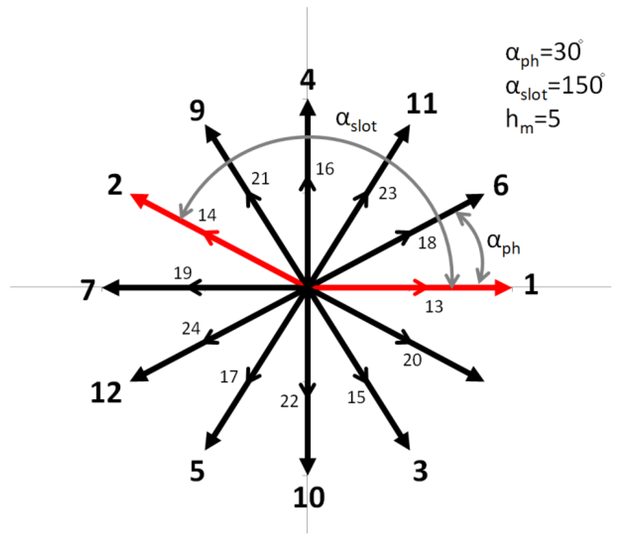
- αph—angle between adjacent phasors in a star of slots,
- αslot—angle between adjacent slots in the star of slots,
- GCD—greatest common divisor,
- kg—winding group factor for the fundamental harmonic,
- ks—winding factor for the fundamental harmonic,
- kw—main winding factor for the fundamental harmonic.
- 2p = 12, f = 480 Hz
- 2p = 14, f = 560 Hz
- 2p = 16, f = 640 Hz
- 2p = 18, f = 720 Hz
- 2p = 20, f = 800 Hz
- 2p = 22, f = 880 Hz
- 2p = 20, f = 960 Hz
- 2p = 14, Qs = 12
- 2p = 16, Qs = 15
- 2p = 20, Qs = 15
- 2p = 20, Qs = 18
- 2p = 22, Qs = 18
- 2p = 22, Qs = 21
- 2p = 24, Qs = 18
- 2p = 12, Qs = 18
- 2p = 14, Qs = 21
- 2p = 16, Qs = 24
- 2p = 18, Qs = 27
- 2p = 20, Qs = 30
- 2p = 22, Qs = 33
- 2p = 24, Qs = 36
- 2p = 14, Qs = 15
- 2p = 14, Qs = 18
- 2p = 16, Qs = 18
- 2p = 16, Qs = 21
- 2p = 20, Qs = 21
- 2p = 20, Qs = 24
- 2p = 20, Qs = 27
- 2p = 22, Qs = 24
- 2p = 22, Qs = 27
- 2p = 22, Qs = 30
- 2p = 24, Qs = 27
4. Slot-Pole Combinations—FEM Analysis
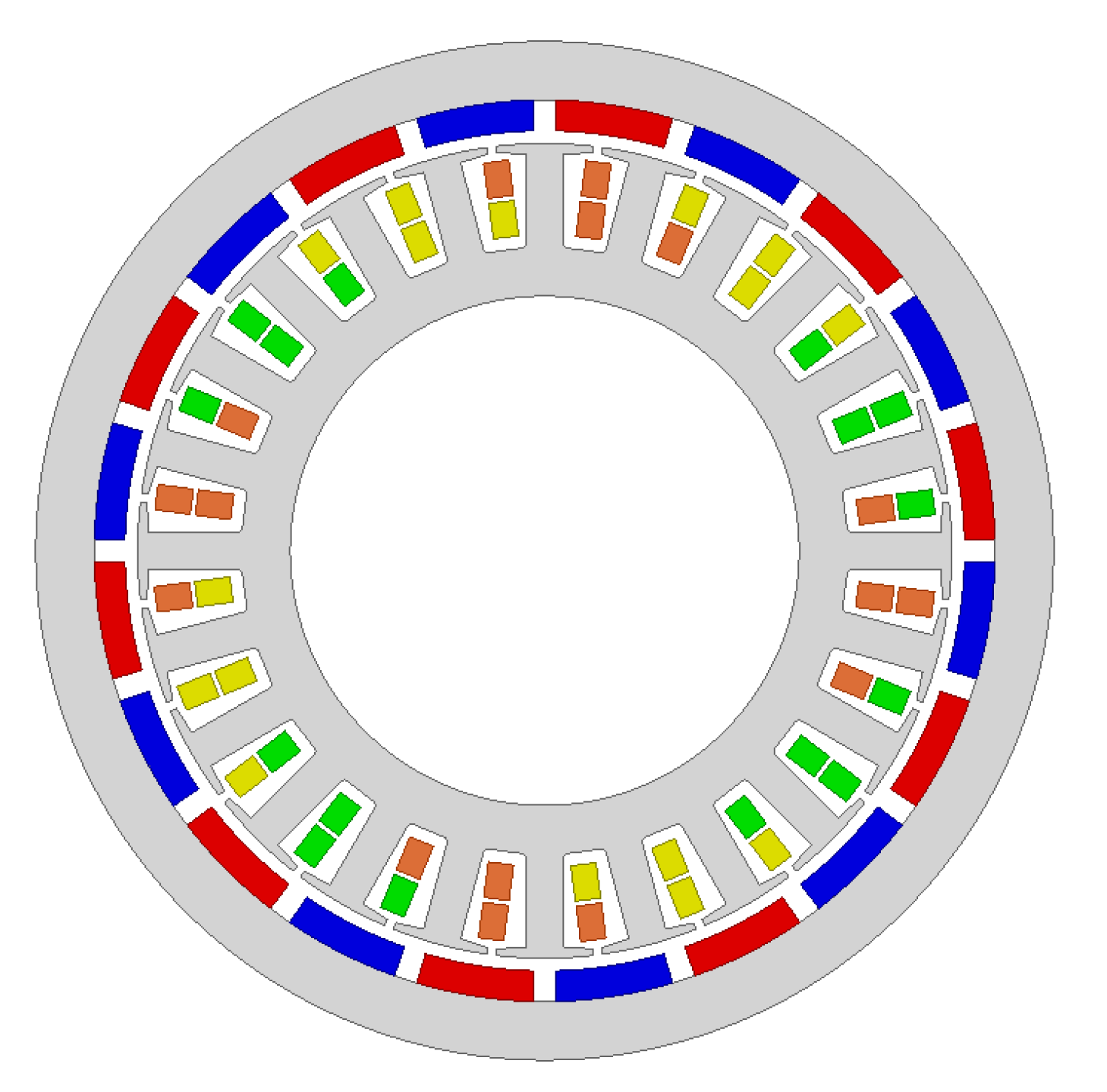
- 2p = 12, Qs = 18, q = 0.5
- 2p = 14, Qs = 18, q = 0.429
- 2p = 16, Qs = 18, q = 0.375
- 2p = 16, Qs = 21, q = 0.438
- 2p = 18, Qs = 27, q = 0.5
- 2p = 20, Qs = 18, q = 0.3
- 2p = 20, Qs = 21, q = 0.35
- 2p = 20, Qs = 24, q = 0.4
- 2p = 20, Qs = 30, q = 0.5
- 2p = 22, Qs = 24, q = 0.364
- 2p = 22, Qs = 27, q = 0.409
- 2p = 24, Qs = 27, q = 0.375
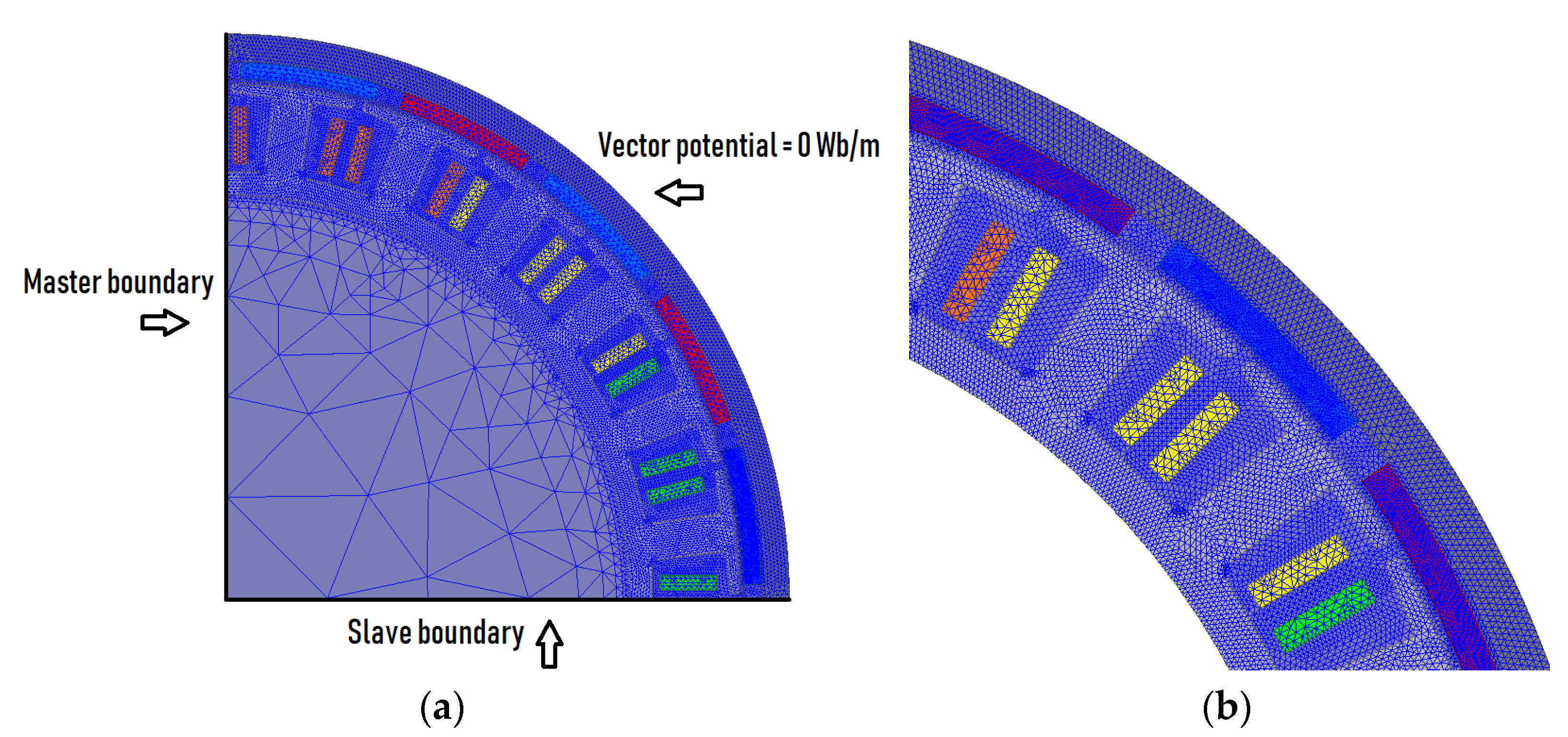
- Magnets—0.4 mm,
- Rotor yoke—1.2 mm,
- Stator core—0.9 mm,
- Outer region—0.8 mm,
- A—the magnetic vector potential,
- J—the source current density,
- V—the electric vector potential,
- Hc—coercivity of the permanent magnet,
- µ—permeability,
- σ—conductivity.
4.1. Shaft Torque and Shaft Power
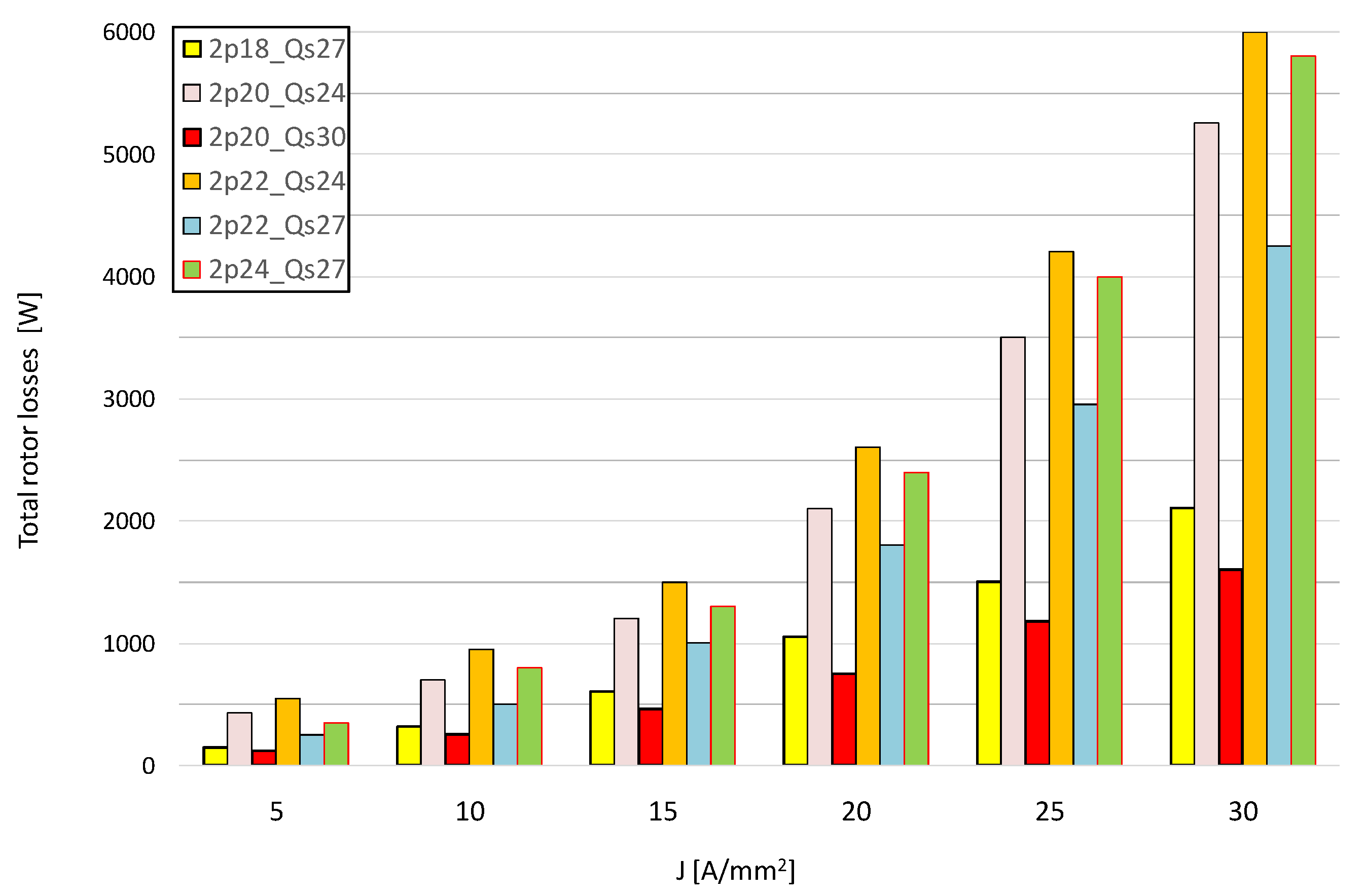
4.2. Rotor Losses
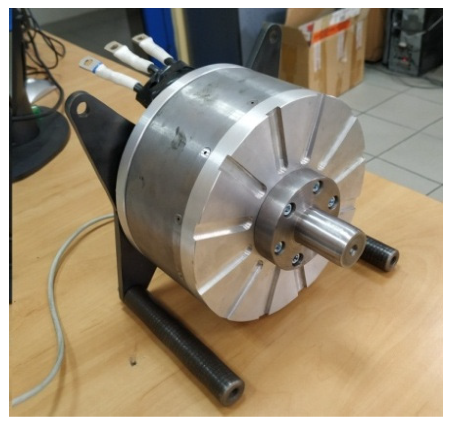
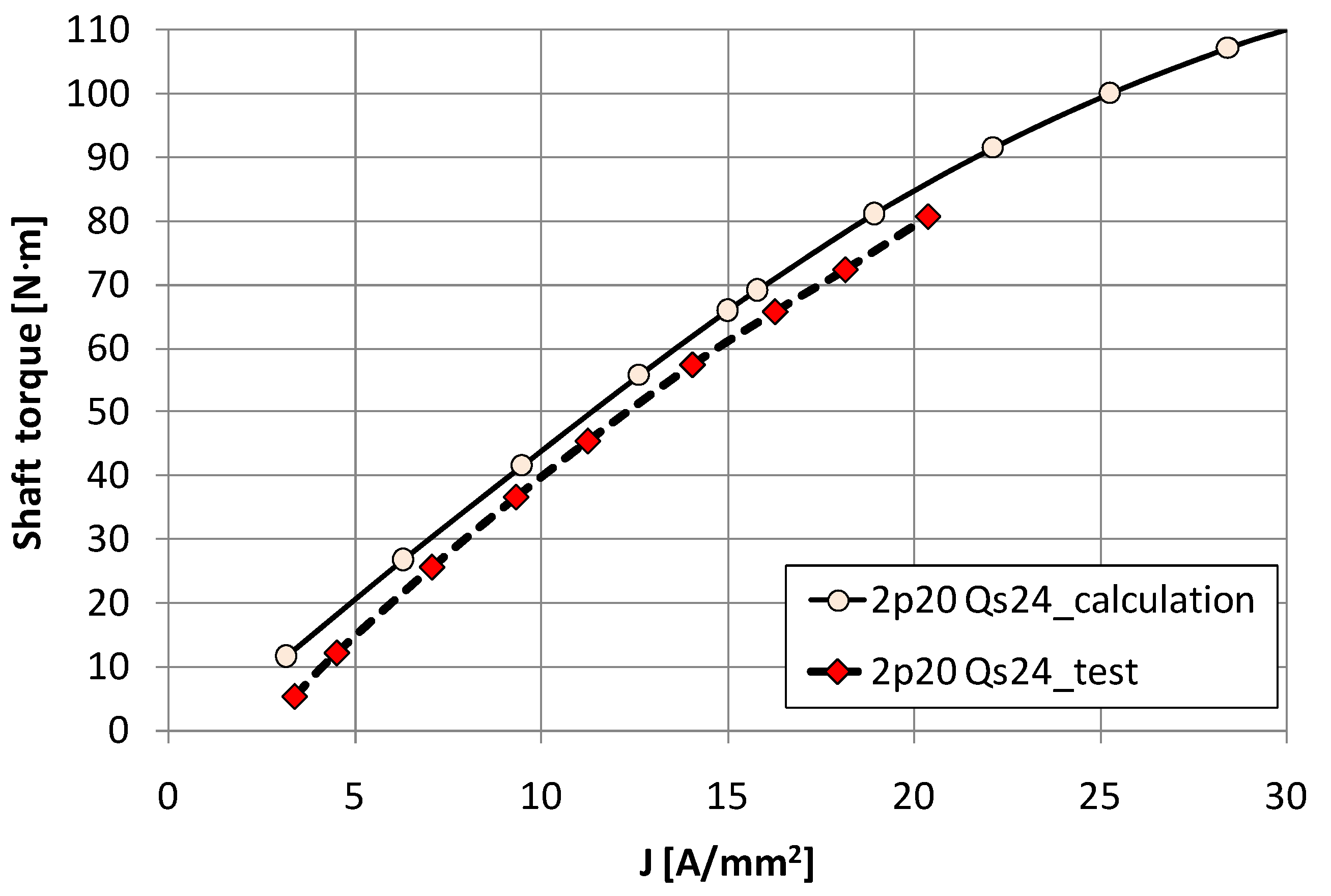
5. Experimental Verification
- the introduced skew of the magnets,
- a higher actual temperature of the magnets (120 °C) than assumed in the calculations (80 °C),
- possible control inaccuracies due to incorrectly read encoder signals.
6. Conclusions
- The following conclusions can be drawn from the analysis carried out in this paper:
- For fractional-slot motors with high power density, the key issue at the design stage is the correct selection of both the number of magnetic poles to the specific dimensions and operating conditions of the motor, as well as the slot-pole combinations. This choice significantly determines the parameters of the motor and its operating capabilities.
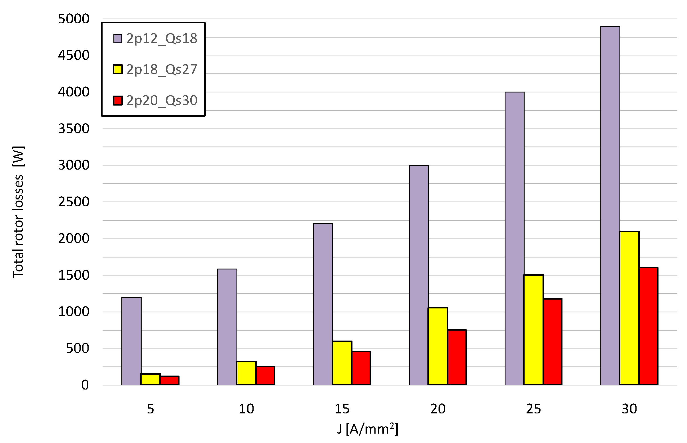
- For the analyzed motor case (approximately 10 kg, max. 4800 r/min, outer diameter 200 mm, solid rotor core) in terms of the power density factor the best solution is the combination 24-pole, 27-slots, although the power frequency for this case is the highest and amounts to f = 960 Hz. For this slot-pole combination, the obtained power density factor is ξ = 6.0 kW/kg and is much better than the other. Based on the test results for the motor 20-pole, 24-slots and due to the similar values of the calculated total rotor losses for the combination 24-pole, 27-slot, it can be assumed that the rotor temperatures for this configuration will also not exceed the permissible values. However, difficulties in controlling and powering the motor at a frequency of 960 Hz should be emphasized. This can be difficult, especially for high current loads.
- The best slot-pole combination in terms of efficiency and the lowest rotor losses are 20-pole, 30-slot (q = 0.5). The rotor losses for this solution are 2.6 times smaller in relation to the 20-pole, 24-slot and 2.8 times lower in relation to the 24-pole, 27-slot.
- In fractional-slot motors, special attention should be paid to the distribution of the magnetomotive force MMF and the winding factor kw for a given slot-pole combinations. These factors largely determine the output parameters of the motor as well as rotor losses. Especially the slot-pole combinations should be avoided, for which there are subharmonics with a large amplitude value in the MMF harmonic distribution. This is the case when the number of stator slots Qs is smaller than the number of magnetic poles 2p.
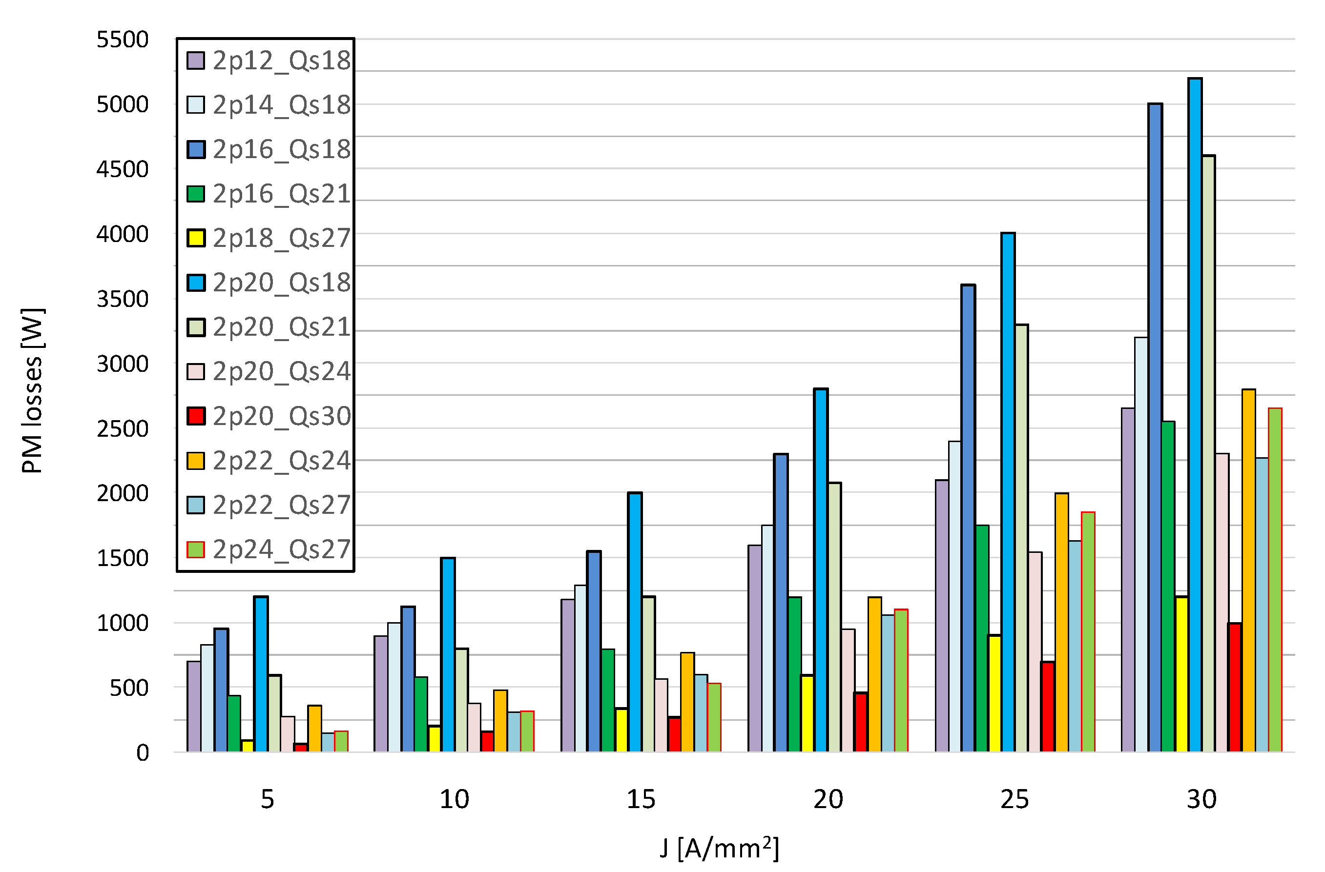
- The slot-pole combinations for which the coefficient q = 0.5 (no subharmonics in the MMF distribution) are characterized by the lowest value of rotor losses, provided that the number of magnetic poles of the motor is appropriately selected for its overall dimensions and operating conditions. The magnet losses depend not only on the distribution of the MMF, but also on e.g., the actual dimensions and volumes of the permanent magnets, which may be different for a different number of magnetic poles 2p of the motor.
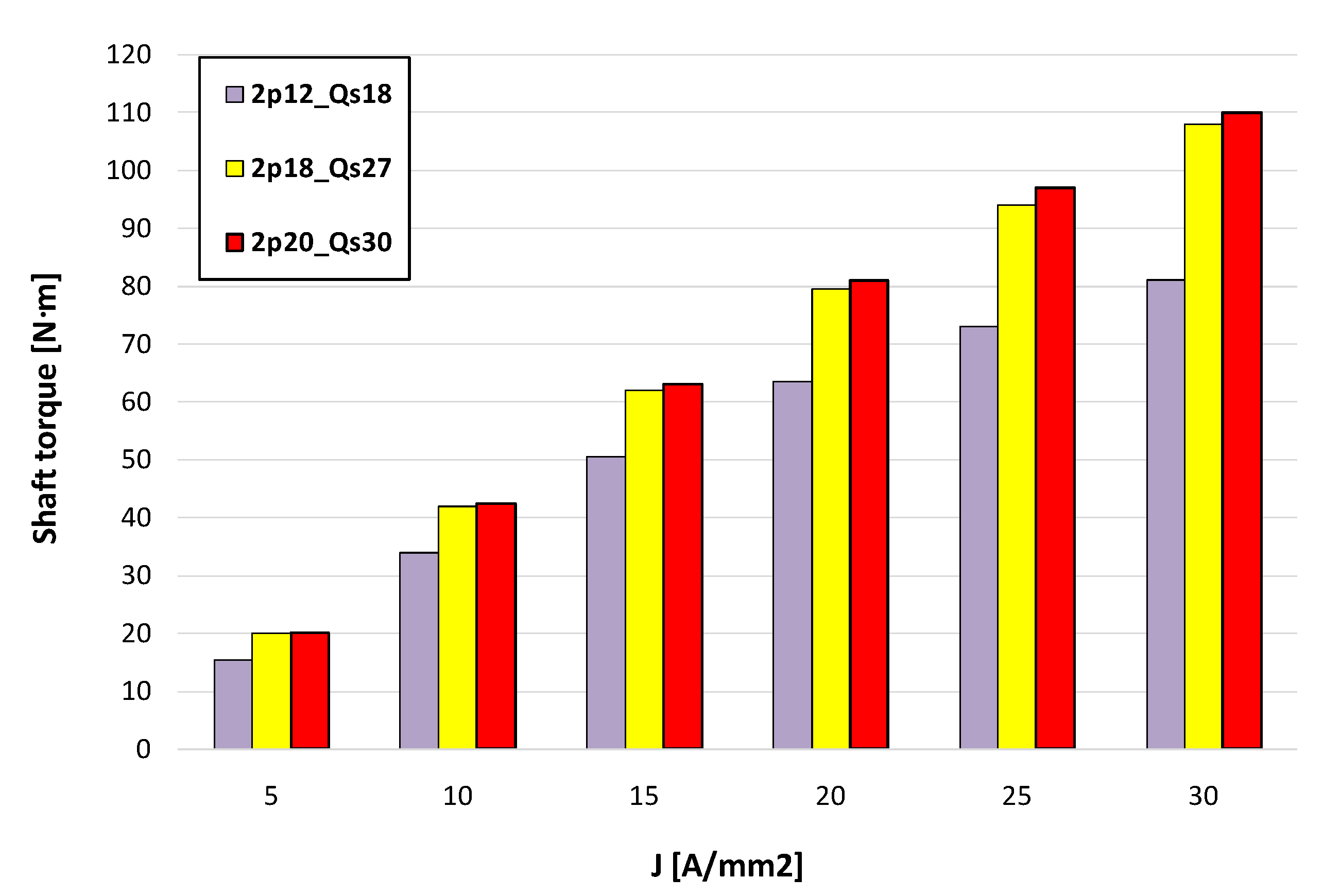
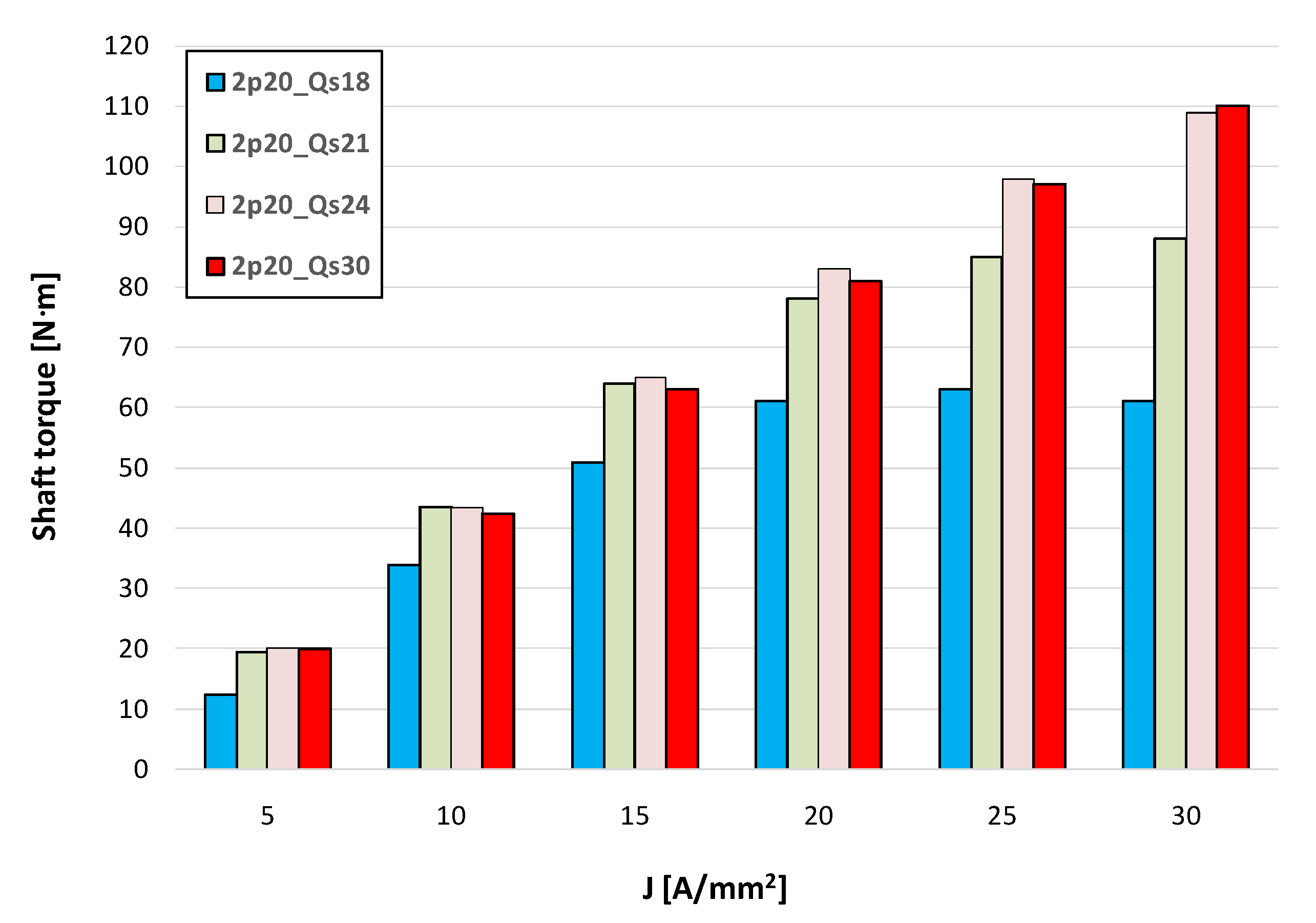
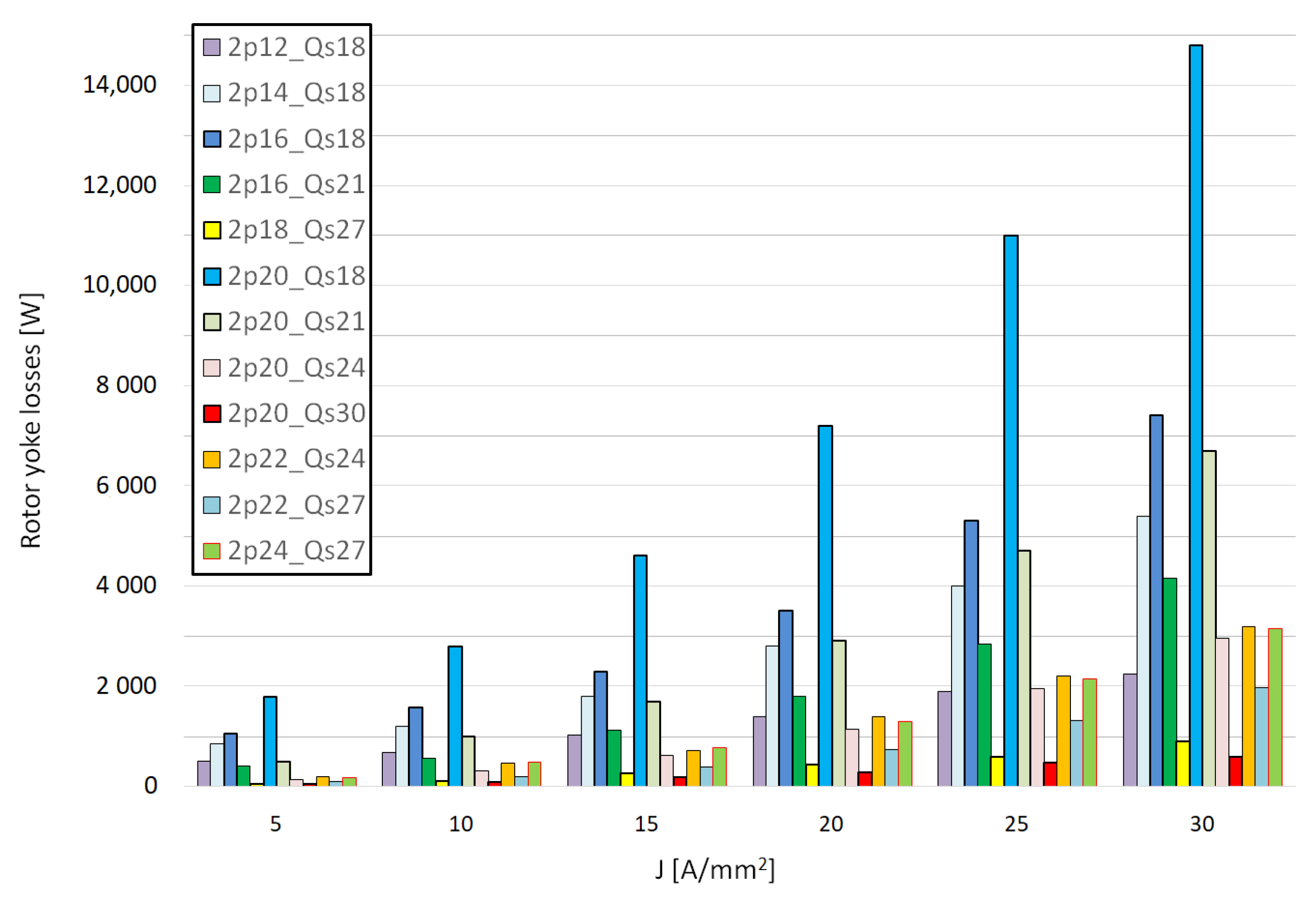
- The selection of the number of magnetic poles to the geometrical dimensions and operational conditions affects the value of the output motor parameters and the rotor losses. It should be noted that the target solution cannot be predicted solely on the basis of the theoretically favorable q value and the winding factor kw. This has been shown in Figure 7 and Figure 12, where we observe different values of shaft torque and significantly different values of rotor losses, despite the fact that the solutions have this same q = 0.5 and winding factor kw = 0.866.
- Comparisons of solutions for slot-pole combinations should be made only on the basis of shaft torque and shaft power, not electromagnetic torque and power. The electromagnetic power in the PMSM motor is reduced by the losses in the stator core and losses in rotor components. In the case of a significant share of these losses in the total losses, it is of key importance, as otherwise the conclusions drawn may be wrong.
- The study assumes a solid rotor core and no circumferential segmentation of the magnets. The main reason was technological and mechanical considerations. However, these assumptions have a significant impact on the results. Core losses can be limited by using a laminated core, while magnet losses can be limited by circumferential segmentation of the magnets [37]. In the case of a solid rotor core, the share of the rotor yoke losses in the total rotor losses is significant and amounts to approximately 50% or more for most slot-pole combinations.
Author Contributions
Funding
Institutional Review Board Statement
Informed Consent Statement
Data Availability Statement
Conflicts of Interest
References
- Ramesh, P.; Lenin, C.N. High Power Density Electrical Machines for Electric Vehicles—Comprehensive Review Based on Material Technology. IEEE Trans. Magn. 2019, 55, 1–21. [Google Scholar] [CrossRef]
- Fulai, G.; Chengning, Z. Oil-cooling method of the permanent magnet synchronous motor for electric vehicle. Energies 2019, 12, 2984. [Google Scholar]
- EL-Refaie, A.M.; Alexander, J.P.; Galioto, S.; Reddy, P.B.; Huh, K.K.; de Bock, P.; Shen, X. Advanced High-Power-Density Interior Permanent Magnet Motor for Traction Applications. IEEE Trans. Ind. Appl. 2014, 50, 3235–3248. [Google Scholar] [CrossRef]
- Park, H.-J.; Lim, M.-S. Design of High Power Density and High Efficiency Wound-Field Synchronous Motor for Electric Vehicle Traction. IEEE Access 2019, 7, 46677–46685. [Google Scholar] [CrossRef]
- Sudha, B.; Anusha, V.; Sachin, S. A review: High power density motors for electric vehicles. Phys. Conf. Ser. 2020, 1706, 1–8. [Google Scholar] [CrossRef]
- Wolnik, T.; Dukalski, P.; Będkowski, B.; Jarek, T. Selected aspects of designing motor for direct vehicle wheel drive. Prz. Elektrotechniczny (Electr. Rev.) 2020, 96, 150–153. [Google Scholar] [CrossRef]
- Bianchi, N.; Bolognani, S.; Pre, M.D. Magnetic loading of fractional slot three phase PM motors with non overlapped coils. In Proceedings of the IEEE Conference Record of the 2006 IEEE Industry Applications Conference Forty-First IAS Annual Meeting, Tampa, FL, USA, 8–12 October 2006; pp. 35–43. [Google Scholar] [CrossRef]
- EL-Refaie, A.M. Fractional-Slot Concentrated-Windings Synchronous Permanent Magnet Machines: Opportunities and Challenges. IEEE Trans. Ind. Electron. 2010, 57, 107–121. [Google Scholar] [CrossRef]
- Bianchi, N.; Bolognani, S.; Fomasiero, E. A General Approach to Determine the Rotor Losses in Three-Phase Fractional-Slot PM Machines. In Proceedings of the IEEE International Electric Machines & Drives Conference, Antalya, Turkey, 3–5 May 2007; pp. 634–641. [Google Scholar]
- Ishak, D.; Zhu, Z.Q.; Howe, D. Eddy-current loss in the rotor magnets of permanent-magnet brushless machines having a fractional number of slots per pole. IEEE Trans. Magn. 2005, 41, 2462–2469. [Google Scholar] [CrossRef] [Green Version]
- Yu, X.; Guoli, L.; Zhe, Q.; Qiubo, Y.; Zhenggen, Z. Research on rotor magnet loss in fractional-slot concentrated-windings permanent magnet motor. In Proceedings of the 2016 IEEE 11th Conference on Industrial Electronics and Applications (ICIEA), Hefei, China, 5–7 June 2016; pp. 1616–1620. [Google Scholar]
- Atallah, K.; Howe, D.; Mellor, P.H.; Stone, D.A. Rotor loss in permanent-magnet brushless AC machines. IEEE Trans. Ind. Appl. 2000, 36, 1612–1618. [Google Scholar]
- Sang-Yub, L.; Hyun-Kyo, J. Eddy current loss analysis in the rotor of permanent magnet traction motor with high power density. In Proceedings of the 2012 IEEE Vehicle Power and Propulsion Conference (VPPC), Seoul, Korea, 9–12 October 2012; pp. 210–214. [Google Scholar]
- Toda, H.; Xia, Z.; Wang, J.; Atallah, K.; Howe, D. Rotor Eddy-Current Loss in Permanent Magnet Brushless Machines. IEEE Trans. Magn. 2004, 40, 2104–2106. [Google Scholar] [CrossRef] [Green Version]
- Nakano, M.; Kometani, H.; Kawamura, M. A study on eddy-current losses in rotors of surface permanent-magnet synchronous machines. IEEE Trans. Ind. Appl. 2006, 42, 429–435. [Google Scholar] [CrossRef]
- Aslan, B.; Semail, E.; Korecki, J.; Legranger, J. Slot/pole combinations choice for concentrated multiphase machines dedicated to mild-hybrid applications. In Proceedings of the IECON 2011—37th Annual Conference of the IEEE Industrial Electronics Society, Melbourne, Australia, 7–10 November 2011; pp. 3698–3703. [Google Scholar]
- Salah, A.; Elnour, M.; Elnail, K. Investigation on influence the slot/pole combinations on the torque performance for synchronous reluctance machine with distributed and concentrated windings. Phys. Conf. Ser. 2020, 1601, 1–7. [Google Scholar] [CrossRef]
- Goss, J.; Staton, D.; Wrobel, R.; Mellor, P. Brushless AC interior-permanent magnet motor design: Comparison of slot/pole combinations and distributed vs. concentrated windings. In Proceedings of the 2013 IEEE Energy Conversion Congress and Exposition, Denver, CO, USA, 15–19 September 2013; pp. 1213–1219. [Google Scholar]
- Sulaiman, E.; Ahmad, M.Z.; Haron, Z.A.; Kosaka, T. Design Studies and Performance of HEFSM with Various Slot—Pole Combinations for HEV Applications. In Proceedings of the 2012 IEEE International Conference on Power and Energy (PE Con), Kota Kinabalu, Malaysia, 2–5 December 2012; pp. 424–429. [Google Scholar]
- Fatemi, A.; Nehl, T.; Yang, X.; Hao, L.; Gopalakrishnan, S.; Omekanda, A.; Namuduri, C. Design Optimization of an Electric Machine for a 48V Hybrid Vehicle with Comparison of Rotor Technologies and Pole-Slot Combinations. IEEE Trans. Ind. Appl. 2020, 56, 4609–4622. [Google Scholar] [CrossRef]
- Dukalski, P.; Krok, R. Selected Aspects of Decreasing Weight of Motor Dedicated to Wheel Hub Assembly by Increasing Number of Magnetic Poles. Energies 2021, 14, 917. [Google Scholar] [CrossRef]
- Hwang, C.C.; Wu, M.H.; Cheng, S.P. Influence of pole and slot combinations on cogging torque in fractional slot PM motors. J. Magn. Magn. Mater. 2006, 304, e430–e432. [Google Scholar] [CrossRef]
- Mitcham, A.J.; Antonopoulos, G.; Cullen, J.J.A. Favourable slot and pole number combinations for fault-tolerant PM machines. IEE Proc-Electr. Power Appl. 2004, 151, 520–525. [Google Scholar] [CrossRef]
- Valavi, M.; Nysveen, A.; Nilssen, R.; Lorenz, R.D.; Rolvag, T. Influence of Pole and Slot Combinations on Magnetic Forces and Vibration in Low-Speed PM Wind Generators. IEEE Trans. Magn. 2014, 50, 1–11. [Google Scholar] [CrossRef]
- Lin, F.; Zuo, S.G.; Wu, X.D. Electromagnetic vibration and noise analysis of permanent magnet synchronous motor with different slot-pole combinations. IET Electr. Power Appl. 2016, 10, 900–908. [Google Scholar] [CrossRef]
- Zhu, Z.Q.; Mohd Jamil, M.L.; Wu, L.J. Influence of Slot and Pole Number Combinations on Unbalanced Magnetic Force in PM Machines With Diametrically Asymmetric Windings. IEEE Trans. Ind. Appl. 2012, 49, 19–30. [Google Scholar] [CrossRef]
- Peng, B.; Wang, X.; Zhao, W.; Ren, J. Study on Shaft Voltage in Fractional Slot Permanent Magnet Machine With Different Pole and Slot Number Combinations. IEEE Trans. Magn. 2019, 55, 1–5. [Google Scholar] [CrossRef]
- Park, S.-H.; Lee, E.-C.; Lee, G.-J.; Kwon, S.-O.; Lim, M.-S. Effect of Pole and Slot Combination on the AC Joule Loss of Outer-Rotor Permanent Magnet Synchronous Motor Using a High Fill Factor Machined Coil. Energies 2021, 14, 3037. [Google Scholar] [CrossRef]
- Wang, J.; Patel, V.; Wang, W. Fractional-Slot Permanent Magnet Brushless Machines with Low Space Harmonic Contents. IEEE Trans. Magn. 2014, 50, 1–9. [Google Scholar] [CrossRef]
- Zhang, H.; Wallmark, O. Limitations and Constraints of Eddy-Current Loss Models for Interior Permanent-Magnet Motors with Fractional-Slot Concentrated Windings. Energies 2017, 10, 379. [Google Scholar] [CrossRef] [Green Version]
- Zheng, M.; Zhu, Z.Q.; Cai, S.; Li, H.Y.; Liu, Y. Influence of Stator and Rotor Pole Number Combinations on the Electromagnetic Performance of Stator Slot-Opening PM Hybrid-Excited Machine. IEEE Trans. Magn. 2019, 55, 1–10. [Google Scholar] [CrossRef]
- Guo, L.; Wang, H. Research on Stator Slot and Rotor Pole Combination and Pole Arc Coefficient in a Surface-Mounted Permanent Magnet Machine by the Finite Element Method. Energies 2021, 12, 26. [Google Scholar] [CrossRef]
- Wilamowski, B.M.; Irwin, J.D. Power Electronics and Motor Drives, 2nd ed.; CRC Press Taylor & Francis Group: Boca Raton, FL, USA, 2011. [Google Scholar]
- Bianchi, N.; Pre, M.D. Use of the star of slots in designing fractional-slot single-layer synchronous motors. IEE Proc. Electr. Power Appl. 2006, 153, 459–466. [Google Scholar] [CrossRef]
- Wolnik, T.; Styskala, V.; Hrbac, R.; Lyaschenko, A.M. The Problem of Rotor Eddy-Current Losses in A Permanent Magnet Motor with High Power Density. In Proceedings of the International Conference on Intelligent Information Technologies for Industry IITI2021, Sochi, Russia, 30 September–4 October 2021; pp. 501–512. [Google Scholar]
- Marriott, L.W.; Griner, G.C. Induction Motor Modeling Using Coupled Magnetic Field and Electrical Circuit Equations. In Proceedings of the International Compressor Engineering Conference, Tippecanoe, IN, USA; 1992. Available online: https://books.google.com.hk/books/about/Proceedings_of_the_International_Compres.html?id=Z71ZAAAAYAAJ&redir_esc=y (accessed on 21 December 2021).
- Aslan, B.; Semail, E.; Legranger, J. General Analytical Model of Magnet Average Eddy-Current Volume Losses for Comparison of Multiphase PM Machines With Concentrated Winding. IEEE Trans. Energy Convers. 2014, 29, 72–83. [Google Scholar] [CrossRef] [Green Version]








| Parameter | |
|---|---|
| DC supply voltage (V) | 350 |
| Rotational speed (r/min) | 4800 |
| Line to line voltage of motor (for 4800 r/min, I = nom.) (V) | 220–240 V |
| Rated current density (A/mm2) | 15 |
| Phase advance angle | 0 |
| Flux weaking | none |
| Outer diameter of rotor core (mm) | 200 |
| Length of core (mm) | 50 |
| Phase number | 3 |
| Air gap length (mm) | 1 |
| Thickness of PM (mm) | 3 |
| Pole arc coefficient | 0.833 |
| The slot opening width (mm) | 1.8 |
| The slot opening height (mm) | 1.3 |
| Winding temperature (°C) | 120 |
| PM temperature (°C) | 80 |
| Flux density in the stator teeth (T) | 2.0 |
| Flux density in the stator yoke (T) | 1.7 |
| Flux density in the rotor yoke (T) | 1.85–1.9 |
| Rotor yoke material type | S355j2 |
| Stator core material type | NO27, 0.27 mm |
| Type of magnets | N45SH |
| 2p | Qs | q | kw | tm | tg | hm | Ah1 | Ah2 | Ah3 | Ah4 | Ah5 | Ah6 | Ah7 | Ah8 | Ah9 | Ah10 | Ah11 |
|---|---|---|---|---|---|---|---|---|---|---|---|---|---|---|---|---|---|
| 12 | 18 | 0.5 | 0.866 | 6 | 6 | 1 | 0.83 | 0.41 | 0 | 0.21 | 0.17 | 0 | 0.12 | 0.1 | 0 | 0.08 | 0.08 |
| 14 | 12 | 0.286 | 0.933 | 1 | 2 | 7 | 0.26 | 0 | 0 | 0 | 0.71 | 0 | 0.51 | 0 | 0 | 0 | 0.02 |
| 14 | 15 | 0.357 | 0.951 | 1 | 1 | 7 | 0.1 | 0.11 | 0 | 0.13 | 0.16 | 0 | 0.65 | 0.57 | 0 | 0.08 | 0.05 |
| 14 | 18 | 0.429 | 0.902 | 1 | 2 | 7 | 0.22 | 0 | 0 | 0 | 0.16 | 0 | 0.74 | 0 | 0 | 0 | 0.47 |
| 14 | 21 | 0.5 | 0.866 | 7 | 7 | 1 | 0.83 | 0.41 | 0 | 0.21 | 0.17 | 0 | 0.12 | 0.1 | 0 | 0.08 | 0.08 |
| 16 | 15 | 0.313 | 0.951 | 1 | 1 | 8 | 0.1 | 0.11 | 0 | 0.13 | 0.16 | 0 | 0.65 | 0.57 | 0 | 0.08 | 0.05 |
| 16 | 18 | 0.375 | 0.945 | 2 | 2 | 4 | 0.17 | 0.2 | 0 | 0.68 | 0.54 | 0 | 0.06 | 0.02 | 0 | 0.02 | 0.04 |
| 16 | 21 | 0.438 | 0.89 | 1 | 1 | 8 | 0.09 | 0.19 | 0 | 0.09 | 0.07 | 0 | 0.12 | 0.74 | 0 | 0.05 | 0.04 |
| 16 | 24 | 0.5 | 0.866 | 8 | 8 | 1 | 0.83 | 0.41 | 0 | 0.21 | 0.17 | 0 | 0.12 | 0.1 | 0 | 0.08 | 0.08 |
| 18 | 27 | 0.5 | 0.866 | 9 | 9 | 1 | 0.83 | 0.41 | 0 | 0.21 | 0.17 | 0 | 0.12 | 0.1 | 0 | 0.08 | 0.08 |
| 20 | 15 | 0.25 | 0.866 | 5 | 5 | 2 | 0.83 | 0.41 | 0 | 0.21 | 0.17 | 0 | 0.12 | 0.1 | 0 | 0.08 | 0.08 |
| 20 | 18 | 0.30 | 0.945 | 2 | 2 | 5 | 0.17 | 0.20 | 0 | 0.68 | 0.54 | 0 | 0.06 | 0.02 | 0 | 0.02 | 0.04 |
| 20 | 21 | 0.35 | 0.953 | 1 | 1 | 10 | 0.07 | 0.07 | 0 | 0.08 | 0.09 | 0 | 0.12 | 0.15 | 0 | 0.64 | 0.58 |
| 20 | 24 | 0.40 | 0.933 | 2 | 4 | 5 | 0.26 | 0 | 0 | 0 | 0.71 | 0 | 0.51 | 0 | 0 | 0 | 0.02 |
| 20 | 27 | 0.45 | 0.877 | 1 | 1 | 10 | 0.06 | 0.09 | 0 | 0.19 | 0.08 | 0 | 0.05 | 0.06 | 0 | 0.75 | 0.1 |
| 20 | 30 | 0.50 | 0.866 | 10 | 10 | 1 | 0.83 | 0.41 | 0 | 0.21 | 0.17 | 0 | 0.12 | 0.1 | 0 | 0.08 | 0.08 |
| 22 | 18 | 0.273 | 0.902 | 1 | 2 | 11 | 0.22 | 0 | 0 | 0 | 0.16 | 0 | 0.74 | 0 | 0 | 0 | 0.47 |
| 22 | 21 | 0.318 | 0.953 | 1 | 1 | 11 | 0.07 | 0.07 | 0 | 0.08 | 0.09 | 0 | 0.12 | 0.15 | 0 | 0.64 | 0.58 |
| 22 | 24 | 0.364 | 0.949 | 1 | 2 | 11 | 0.13 | 0 | 0 | 0 | 0.15 | 0 | 0.18 | 0 | 0 | 0 | 0.66 |
| 22 | 27 | 0.409 | 0.915 | 1 | 1 | 11 | 0.19 | 0.07 | 0 | 0.14 | 0.05 | 0 | 0.06 | 0.07 | 0 | 0.05 | 0.72 |
| 22 | 30 | 0.455 | 0.874 | 1 | 2 | 11 | 0.11 | 0 | 0 | 0 | 0.19 | 0 | 0.09 | 0 | 0 | 0 | 0.76 |
| 22 | 33 | 0.5 | 0.866 | 11 | 11 | 1 | 0.83 | 0.41 | 0 | 0.21 | 0.17 | 0 | 0.12 | 0.1 | 0 | 0.08 | 0.08 |
| 24 | 18 | 0.25 | 0.866 | 6 | 6 | 2 | 0.83 | 0.41 | 0 | 0.21 | 0.17 | 0 | 0.12 | 0.1 | 0 | 0.08 | 0.08 |
| 24 | 27 | 0.375 | 0.945 | 3 | 3 | 4 | 0.17 | 0.2 | 0 | 0.68 | 0.54 | 0 | 0.06 | 0.02 | 0 | 0.02 | 0.04 |
| 24 | 36 | 0.5 | 0.866 | 12 | 12 | 1 | 0.83 | 0.41 | 0 | 0.21 | 0.17 | 0 | 0.12 | 0.1 | 0 | 0.08 | 0.08 |
| Slot-Pole | ΔPCu | ΔPFe | ΔPYr | ΔPPM | ΔPTr | ΔPadd | ΔPmech | Pshaft | Tshaft | η | ξ | kw | |
|---|---|---|---|---|---|---|---|---|---|---|---|---|---|
| W | W | W | W | W | W | W | kW | N·m | % | kW/kg | |||
| 2p = 12, Qs = 18 | 1283 | 387 | 978 | 1164 | 2142 | 425 | 260 | 25.5 | 50.8 | 85.0% | 2.4 | 0.866 | 0.98 |
| 2p = 14, Qs = 18 | 1308 | 589 | 1835 | 1287 | 3122 | 464 | 260 | 27.0 | 52.8 | 82.2% | 2.6 | 0.902 | 0.91 |
| 2p = 16, Qs = 18 | 1308 | 1316 | 2310 | 1533 | 3843 | 587 | 260 | 33.7 | 67.1 | 82.2% | 3.2 | 0.945 | 0.87 |
| 2p = 16, Qs = 21 | 1333 | 1142 | 1125 | 801 | 1926 | 506 | 260 | 30.4 | 60.5 | 85.5% | 2.9 | 0.890 | 0.96 |
| 2p = 18, Qs = 27 | 1110 | 1117 | 260 | 342 | 602 | 501 | 260 | 31.4 | 62.5 | 89.8% | 3.0 | 0.866 | 1.04 |
| 2p = 20, Qs = 18 | 1330 | 2005 | 4693 | 2015 | 6708 | 532 | 260 | 26.5 | 52.6 | 71.0% | 2.5 | 0.945 | 0.75 |
| 2p = 20, Qs = 21 | 1289 | 1480 | 1706 | 1214 | 2920 | 563 | 260 | 32.9 | 65.4 | 83.5% | 3.1 | 0.953 | 0.88 |
| 2p = 20, Qs = 24 | 1170 | 923 | 635 | 567 | 1202 | 533 | 260 | 33.2 | 66.0 | 89.0% | 3.2 | 0.933 | 0.95 |
| 2p = 20, Qs = 30 | 1091 | 1263 | 191 | 273 | 464 | 512 | 260 | 32.1 | 63.9 | 90.0% | 3.1 | 0.866 | 1.04 |
| 2p = 22, Qs = 24 | 1170 | 1052 | 762 | 740 | 1502 | 551 | 260 | 33.9 | 67.5 | 88.2% | 3.2 | 0.949 | 0.93 |
| 2p = 22, Qs = 27 | 1109 | 1144 | 387 | 597 | 984 | 551 | 260 | 34.3 | 68.3 | 89.5% | 3.3 | 0.915 | 0.98 |
| 2p = 24, Qs = 27 | 1116 | 1660 | 774 | 533 | 1307 | 606 | 260 | 37.2 | 74.0 | 88.3% | 3.5 | 0.945 | 0.93 |
| Slot-Pole | ΔPCu | ΔPFe | ΔPYr | ΔPPM | ΔPTr | ΔPadd | ΔPmech | Pshaft | Tshaft | η | ξ | kw | |
|---|---|---|---|---|---|---|---|---|---|---|---|---|---|
| W | W | W | W | W | W | W | kW | N·m | % | kW/kg | |||
| 2p = 12, Qs = 18 | 5130 | 670 | 2275 | 2616 | 4891 | 702 | 260 | 41.0 | 81.6 | 77.9% | 3.9 | 0.866 | 0.90 |
| 2p = 14, Qs = 18 | 5231 | 1128 | 5324 | 3227 | 8551 | 768 | 260 | 41.3 | 82.1 | 72.1% | 3.9 | 0.902 | 0.80 |
| 2p = 16, Qs = 18 | 5231 | 2286 | 7374 | 5044 | 12,418 | 1012 | 260 | 52.5 | 104.4 | 71.2% | 5.0 | 0.945 | 0.75 |
| 2p = 16, Qs = 21 | 5332 | 1901 | 4161 | 2564 | 6725 | 831 | 260 | 46.6 | 92.6 | 75.6% | 4.4 | 0.890 | 0.85 |
| 2p = 18, Qs = 27 | 4440 | 1504 | 852 | 1191 | 2043 | 871 | 260 | 54.2 | 107.9 | 85.6% | 5.2 | 0.866 | 0.99 |
| 2p = 20, Qs = 18 | 5318 | 3603 | 14,875 | 5239 | 20,114 | 831 | 260 | 31.4 | 62.5 | 51.0% | 3.0 | 0.945 | 0.54 |
| 2p = 20, Qs = 21 | 5124 | 2752 | 6639 | 4670 | 11,309 | 891 | 260 | 45.1 | 89.6 | 68.9% | 4.3 | 0.953 | 0.72 |
| 2p = 20, Qs = 24 | 4679 | 1095 | 2933 | 2280 | 5213 | 929 | 260 | 55.4 | 110.1 | 82.0% | 5.3 | 0.933 | 0.88 |
| 2p = 20, Qs = 30 | 4364 | 1618 | 620 | 979 | 1599 | 897 | 260 | 56.3 | 112.1 | 86.6% | 5.4 | 0.866 | 1.00 |
| 2p = 22, Qs = 24 | 4679 | 1290 | 3338 | 2884 | 6222 | 942 | 260 | 55.0 | 109.4 | 80.4% | 5.2 | 0.949 | 0.85 |
| 2p = 22, Qs = 27 | 4437 | 1611 | 1909 | 2266 | 4175 | 985 | 260 | 59.6 | 118.6 | 83.9% | 5.7 | 0.915 | 0.92 |
| 2p = 24, Qs = 27 | 4464 | 2 626 | 3086 | 2604 | 5690 | 1079 | 260 | 63.4 | 126.1 | 81.8% | 6.0 | 0.945 | 0.87 |
| J | Pin | Pshaft | Tshaft | ΣΔP | η |
|---|---|---|---|---|---|
| A/mm2 | kW | kW | N·m | kW | % |
| 3.4 | 4.6 | 2.7 | 5.4 | 2.0 | 58.1 |
| 4.5 | 8.3 | 6.2 | 12.3 | 2.1 | 75.0 |
| 7.1 | 15.2 | 12.9 | 25.6 | 2.3 | 85.1 |
| 9.4 | 20.9 | 18.4 | 36.6 | 2.5 | 88.1 |
| 11.4 | 25.5 | 22.8 | 45.4 | 2.7 | 89.3 |
| 14.3 | 32.3 | 28.9 | 57.4 | 3.4 | 89.5 |
| 16.6 | 37.1 | 33.1 | 65.9 | 4.0 | 89.3 |
| 18.5 | 40.9 | 36.4 | 72.5 | 4.5 | 89.0 |
| 20.8 | 46.2 | 40.6 | 80.8 | 5.6 | 87.9 |
Publisher’s Note: MDPI stays neutral with regard to jurisdictional claims in published maps and institutional affiliations. |
© 2021 by the authors. Licensee MDPI, Basel, Switzerland. This article is an open access article distributed under the terms and conditions of the Creative Commons Attribution (CC BY) license (https://creativecommons.org/licenses/by/4.0/).
Share and Cite
Wolnik, T.; Styskala, V.; Mlcak, T. Study on the Selection of the Number of Magnetic Poles and the Slot-Pole Combinations in Fractional Slot PMSM Motor with a High Power Density. Energies 2022, 15, 215. https://doi.org/10.3390/en15010215
Wolnik T, Styskala V, Mlcak T. Study on the Selection of the Number of Magnetic Poles and the Slot-Pole Combinations in Fractional Slot PMSM Motor with a High Power Density. Energies. 2022; 15(1):215. https://doi.org/10.3390/en15010215
Chicago/Turabian StyleWolnik, Tomasz, Vítezslav Styskala, and Tomas Mlcak. 2022. "Study on the Selection of the Number of Magnetic Poles and the Slot-Pole Combinations in Fractional Slot PMSM Motor with a High Power Density" Energies 15, no. 1: 215. https://doi.org/10.3390/en15010215
APA StyleWolnik, T., Styskala, V., & Mlcak, T. (2022). Study on the Selection of the Number of Magnetic Poles and the Slot-Pole Combinations in Fractional Slot PMSM Motor with a High Power Density. Energies, 15(1), 215. https://doi.org/10.3390/en15010215


